
Mechanical Properties, Curing Mechanism, and Microscopic Experimental Study of Polypropylene Fiber Coordinated Fly Ash Modified Cement–Silty Soil

Abstract
:1. Introduction
2. Experimental Program
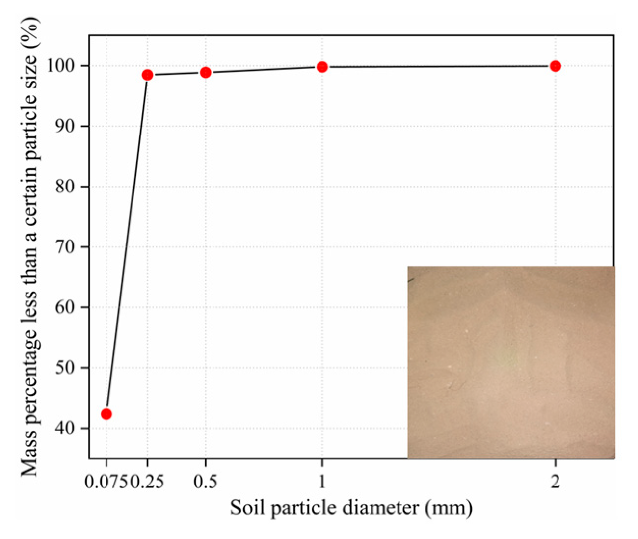
2.1. Materials
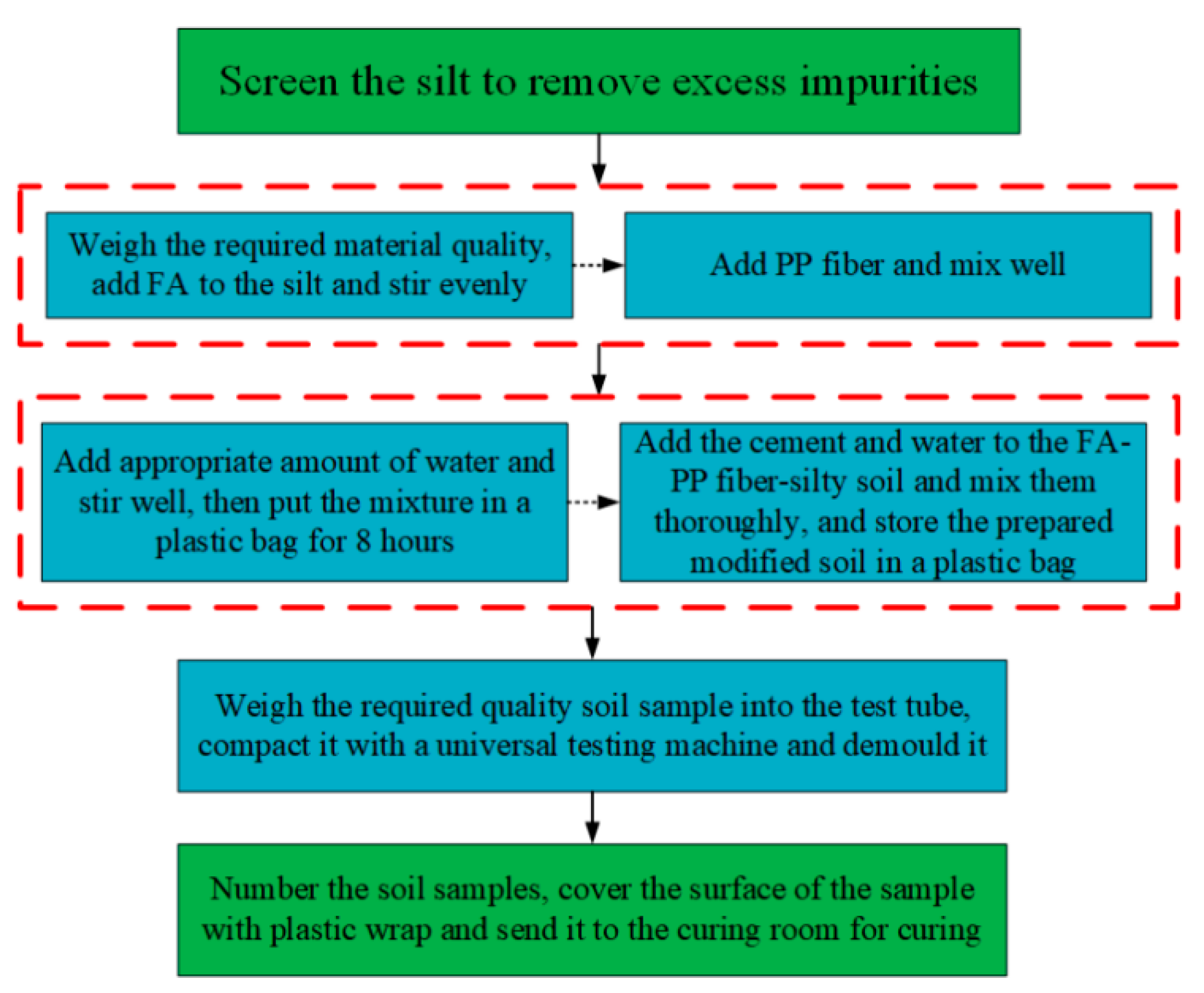
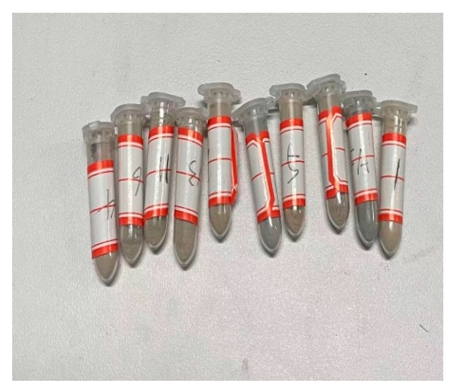
2.2. Sample Preparation
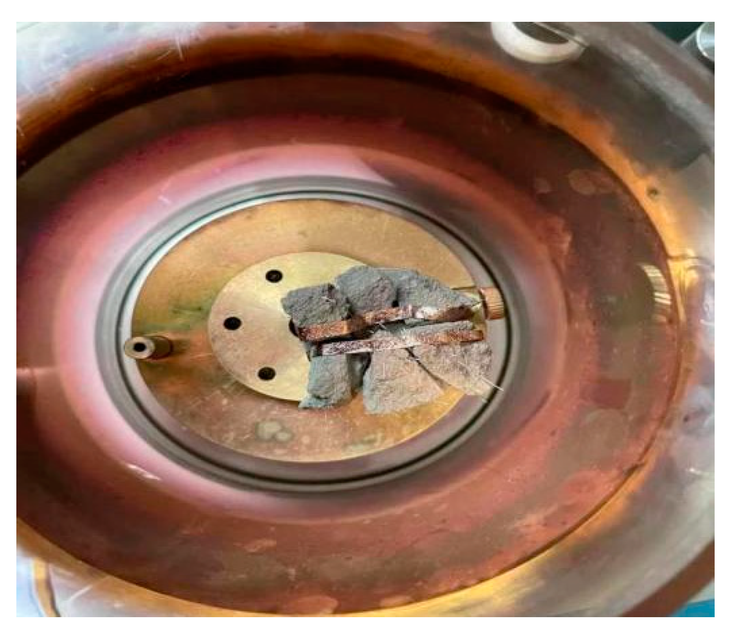
2.3. Experimental Methods
3. Experimental Results
3.1. UCS Test
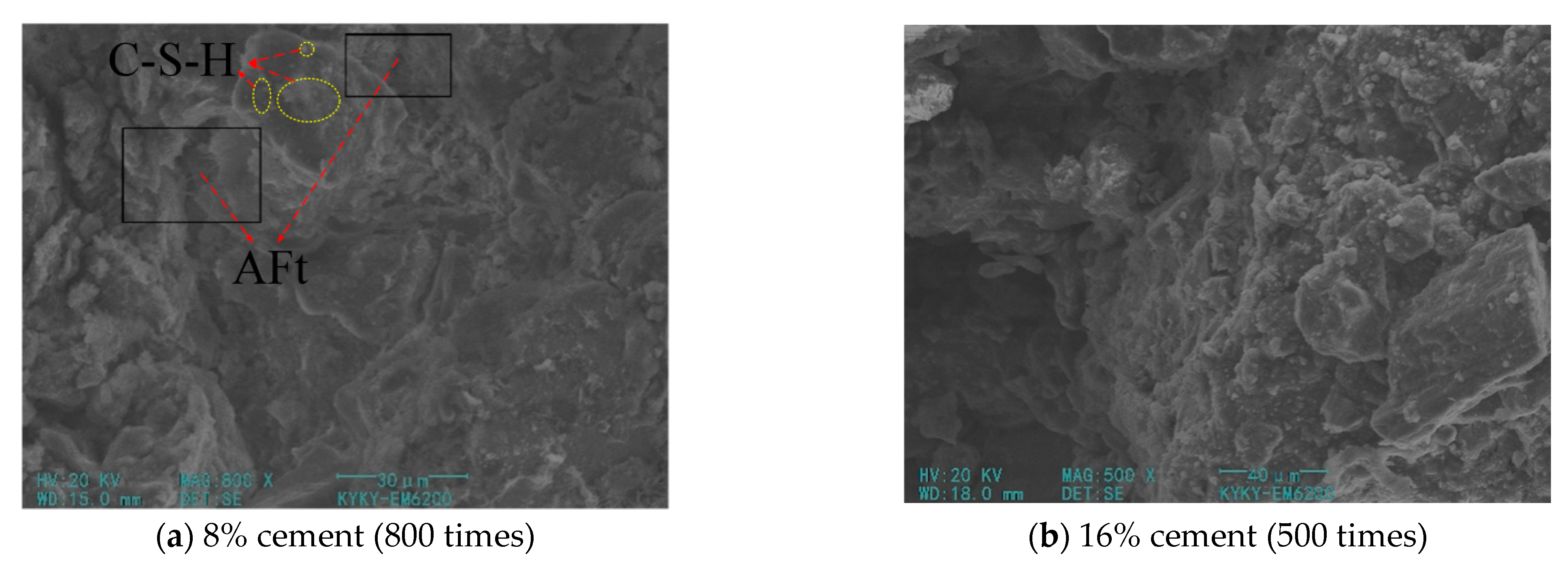
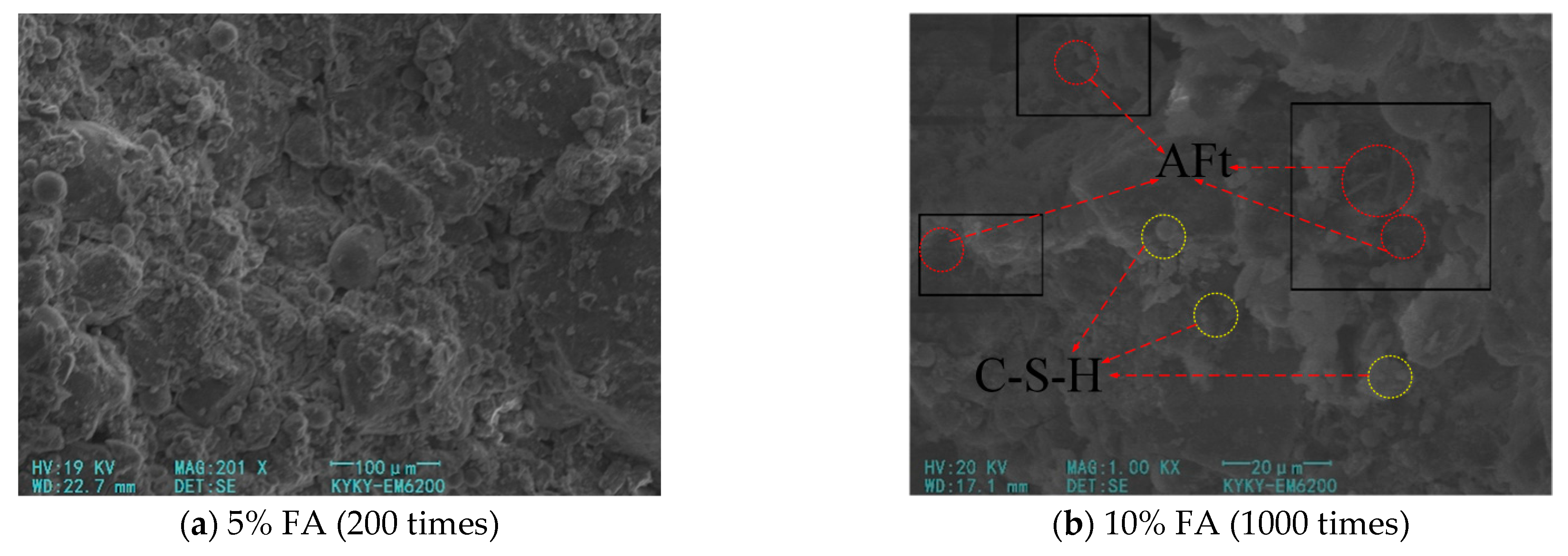
3.2. SEM Test
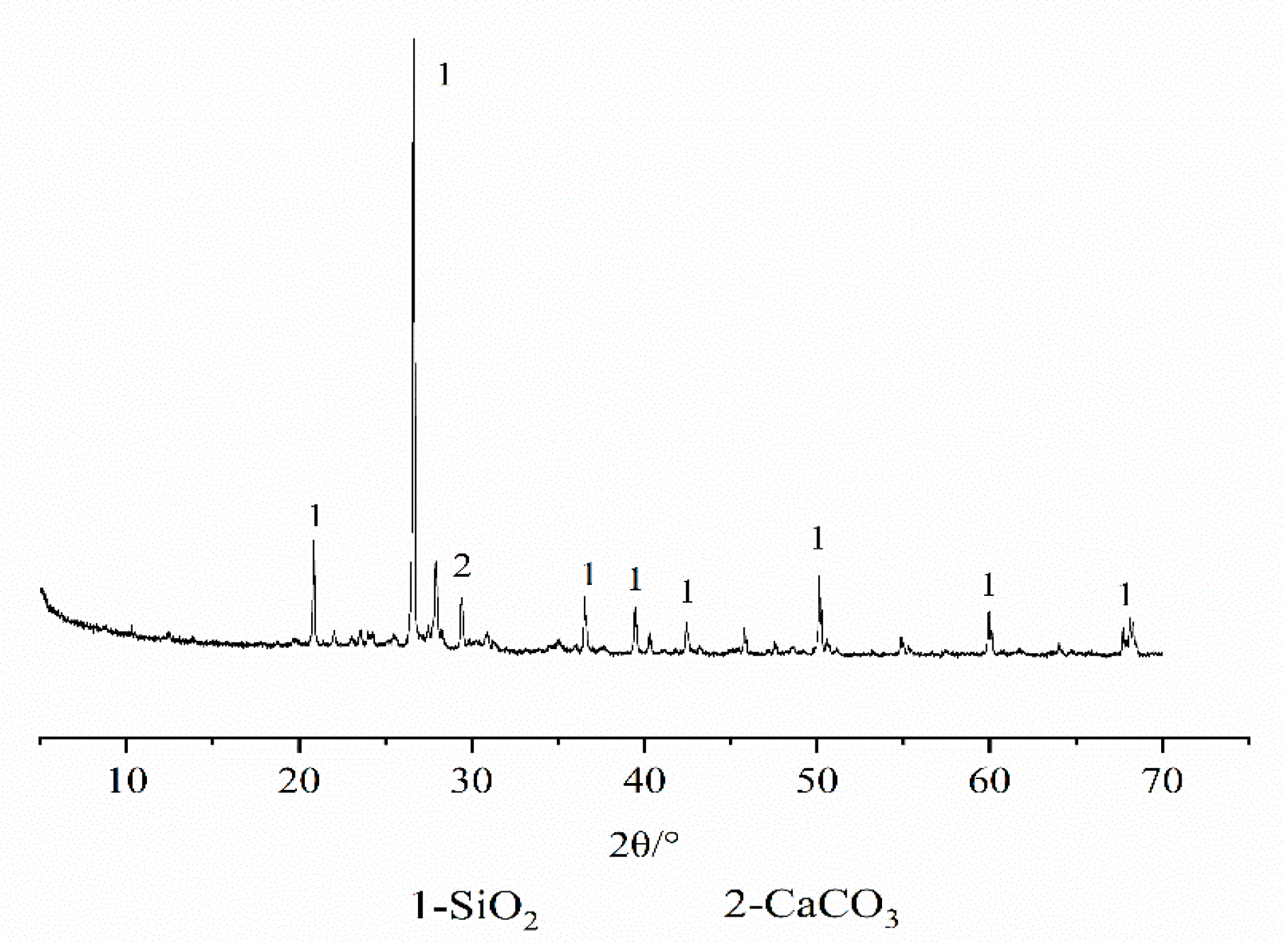
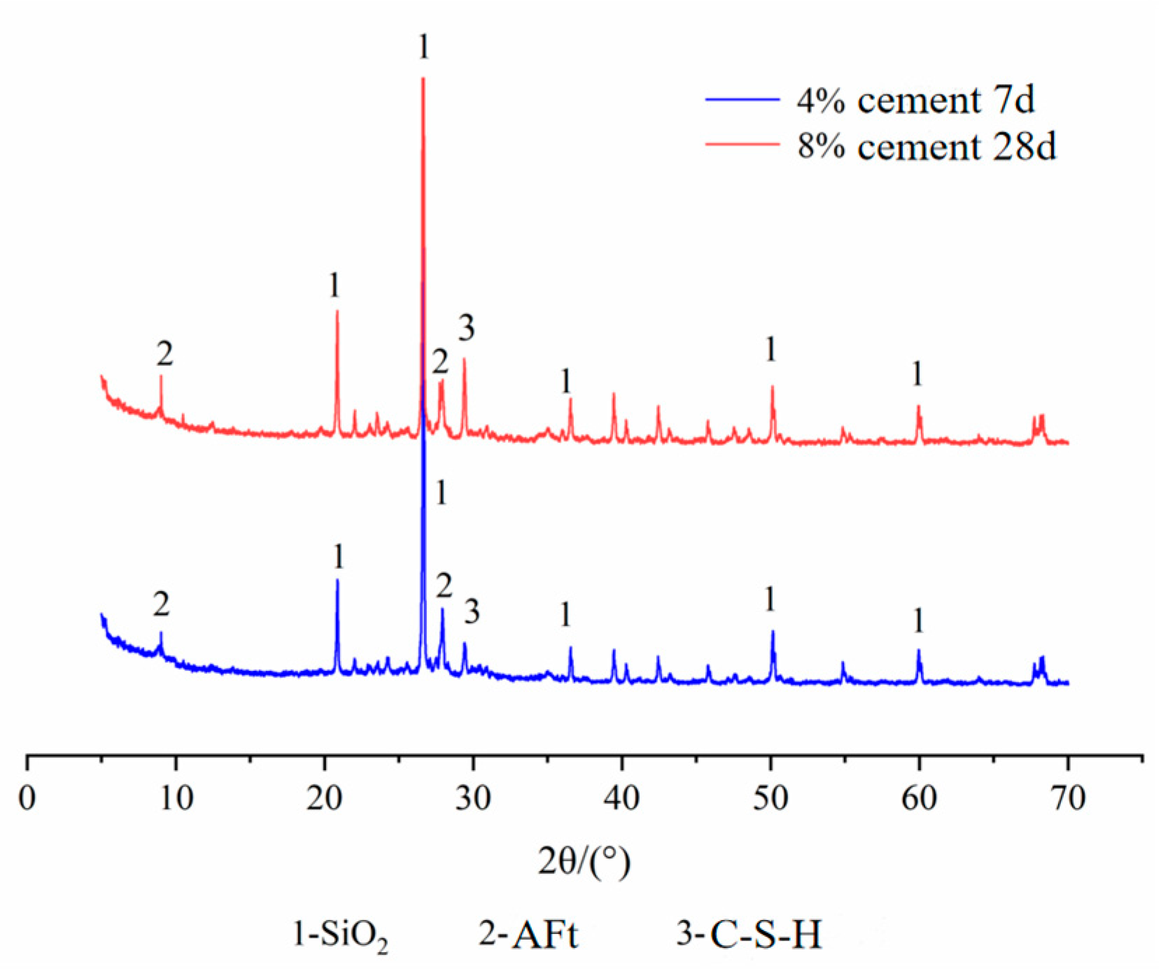
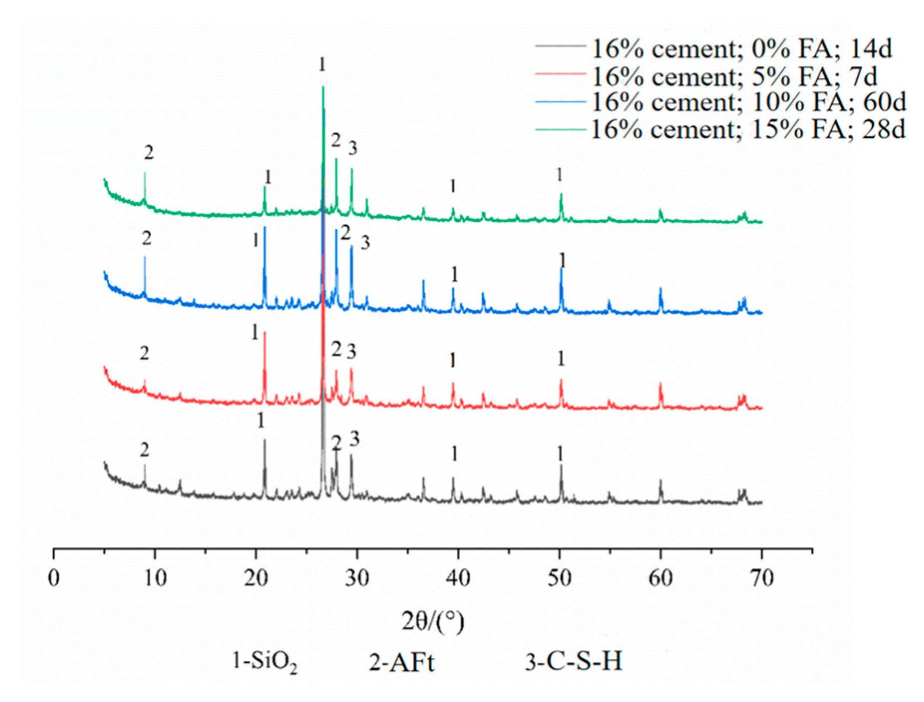
3.3. XRD Test and Analysis
4. Curing Mechanism of PP Fiber–FA–Cement–Soil
4.1. Curing Mechanism of Cement–Soil
4.1.1. Hydrolysis Hydration Reaction of Cement
4.1.2. The Interaction between Silt Particles and Cement Hydrate
4.2. Curing Mechanism of FA on Cement–Soil
4.2.1. The Physical Filling Effect of FA
4.2.2. Hydration Effect of FA
4.3. Curing Mechanism of PP Fiber on Cement–Soil
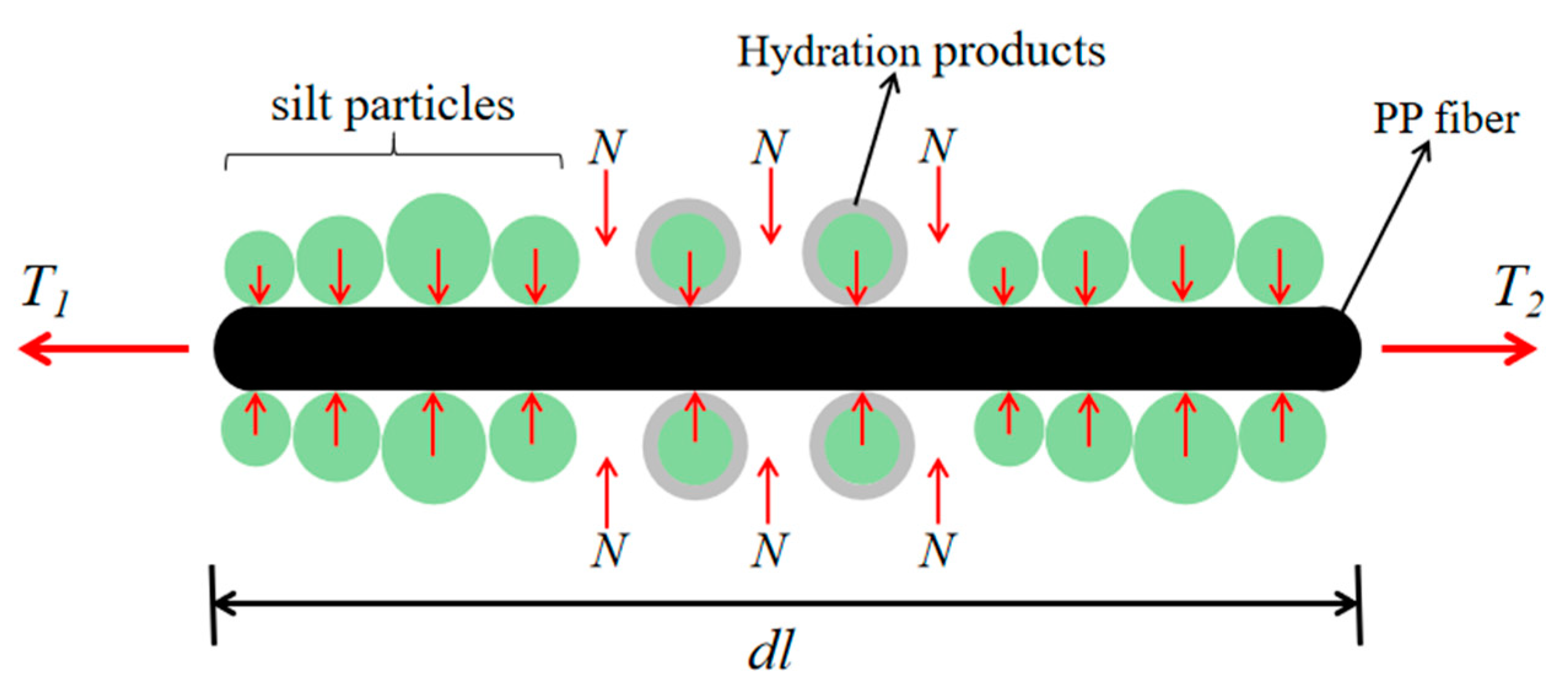
4.3.1. Friction Reinforcement Effect
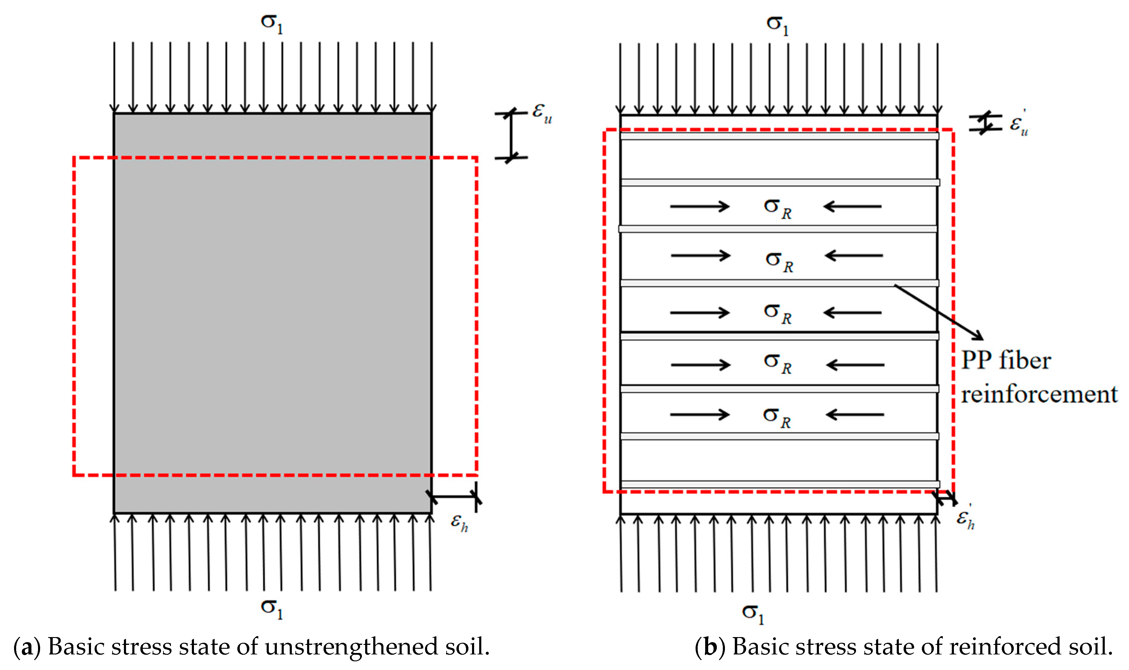
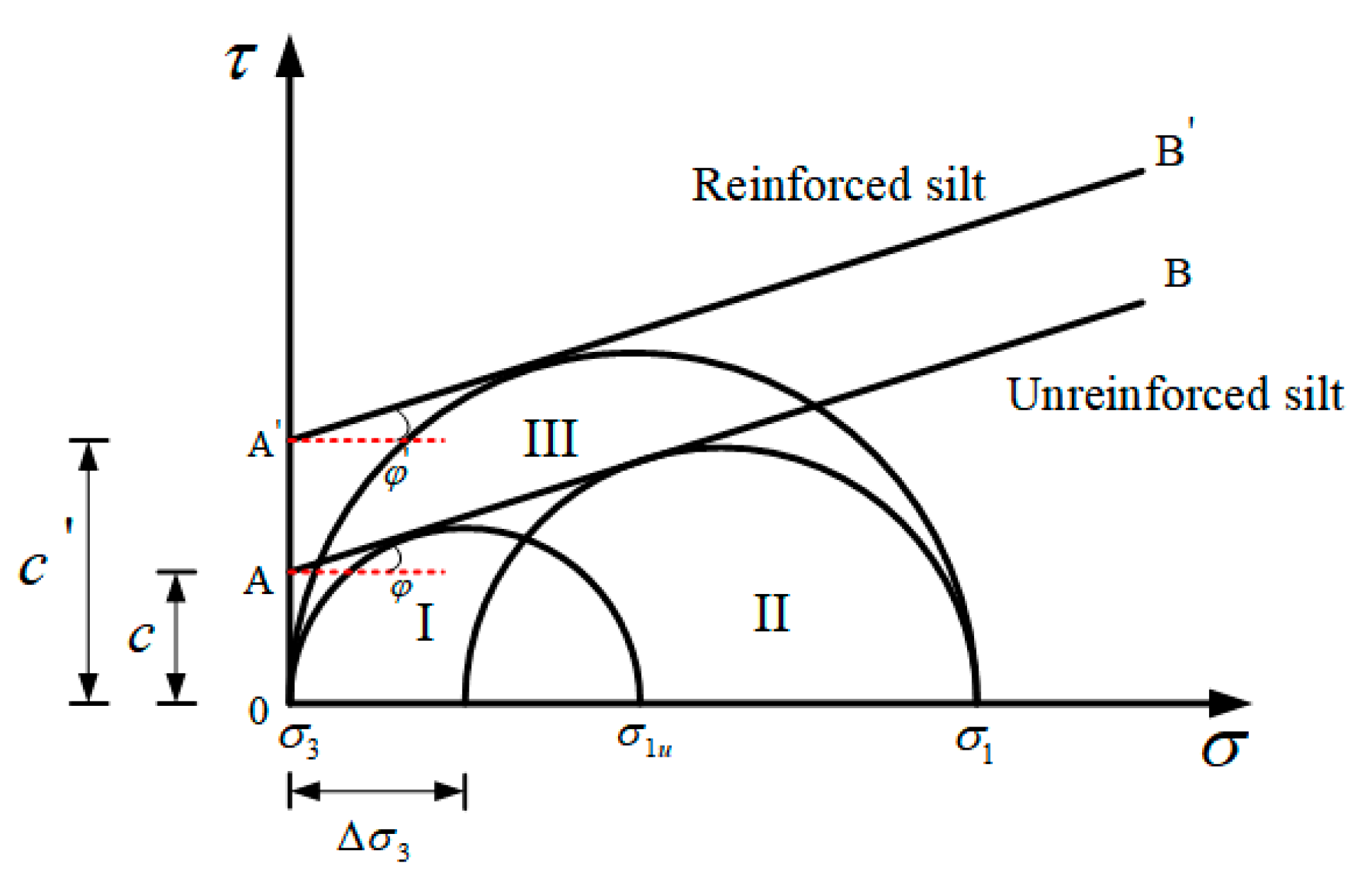
4.3.2. Lateral Restraint Effect
5. Conclusions
- (1)
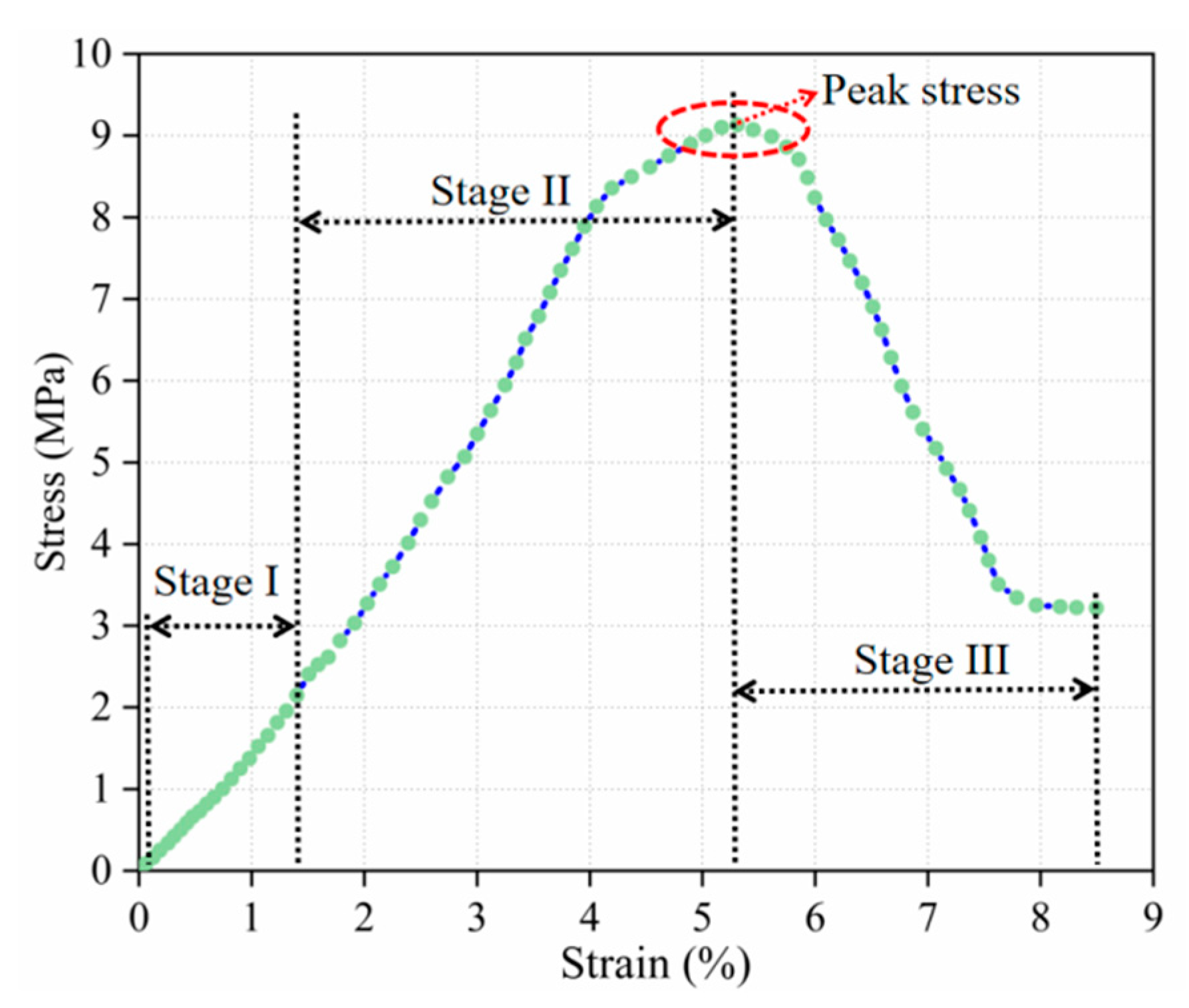
- With the increase in FA and fiber, the strength first increases and then decreases. There is an optimal content of the two. Among them, FA is 10% and fiber is 0.15%. At the same time, combined with the range analysis method to target the strength, the best mix ratio is determined as follows: the cement content is 16%, the FA content is 10%, the PP fiber content is 0.15%, and the curing age is 60 d. At the same time, it is found that the stress and strain development of the modified soil has three stages: namely, the elastic stage, the plastic deformation stage, and the strain-softening stage, and the specimens in each stage had corresponding deformation characteristics.
- (2)
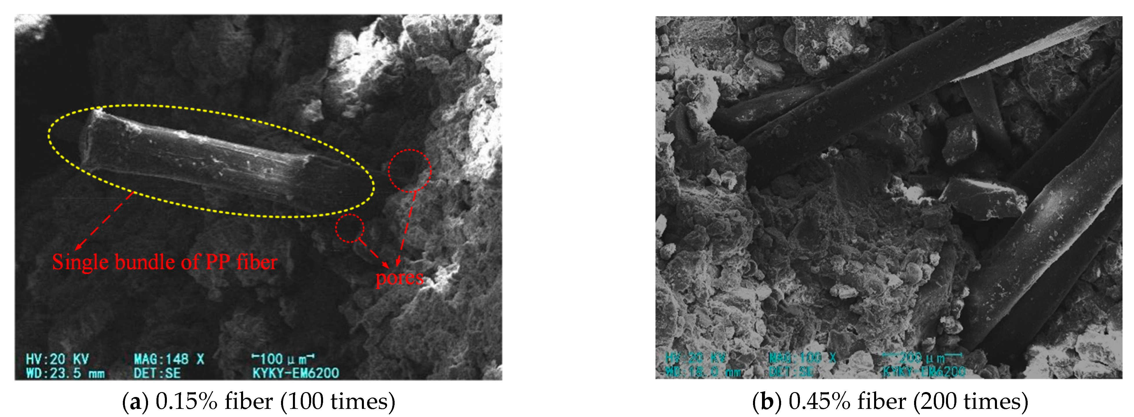
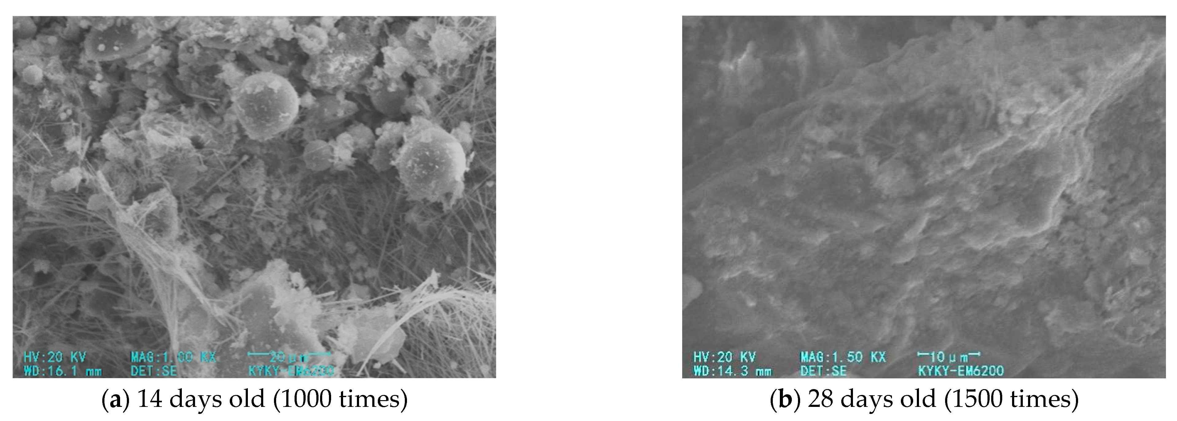
- It can be seen from SEM images that a large amount of cementitious substances and needle-like and layered hydrates are produced in the PP fiber–FA–cement–soil. These products cover the surface of the soil particles or fill the pores between the soil particles, forming a skeleton structure and fiber–soil spatial network structure, enhancing the integrity of the modified soil structure; PP fiber is embedded in the soil particles, and the connection between the two is wrapped in many hydration products, thereby increasing the friction and mechanical bite force between the fibers and the soil–cement particles.
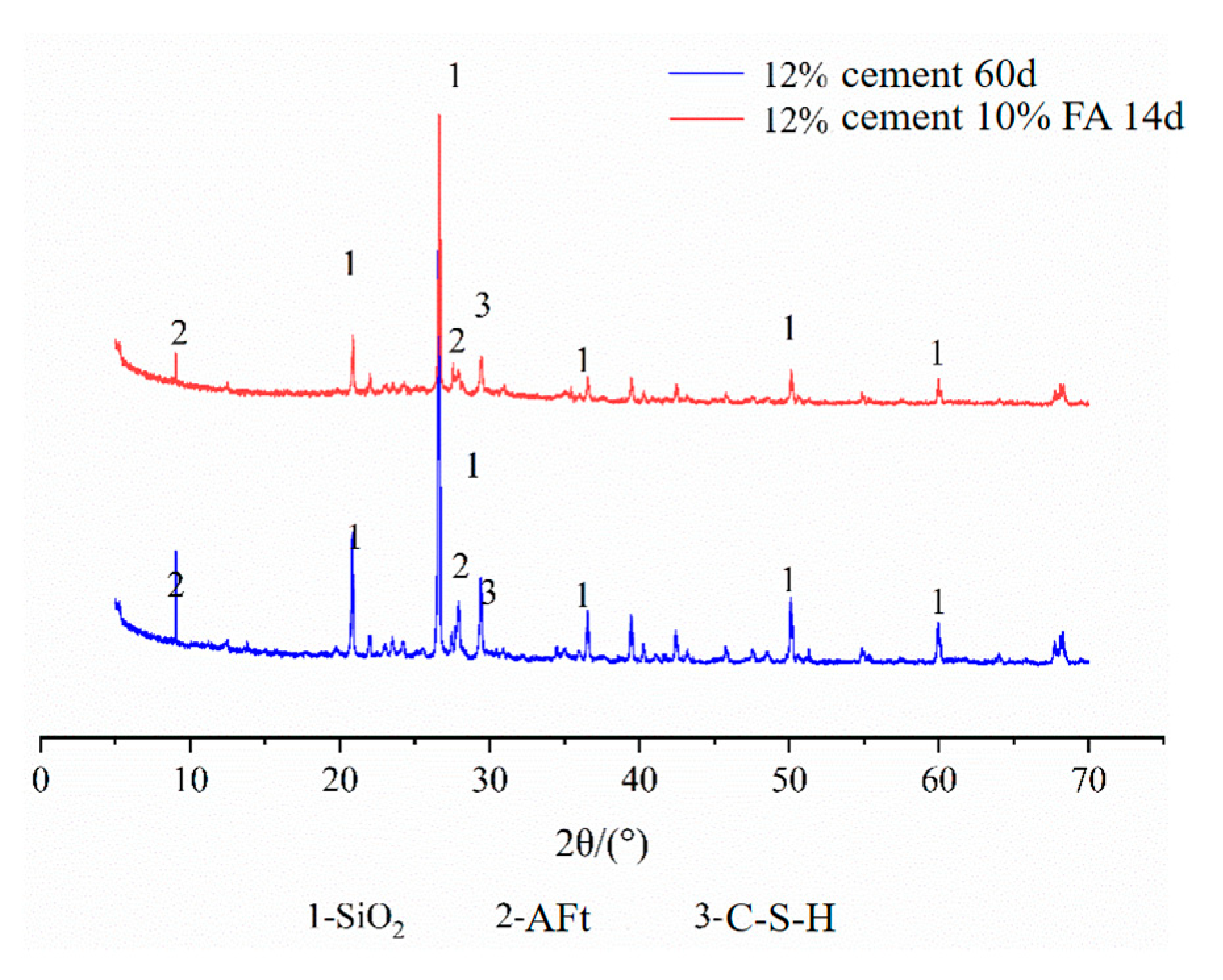
- (3)
- The mineral composition of the modified soil with different mixing ratios is basically the same, mainly SiO2, C-S-H, and AFt, but the diffraction peak intensity of each mineral was different. The samples with large cement content and long curing age have a higher diffraction peak intensity of calcium silicate hydrate and ettringite. The amount of FA has little effect on the intensity of diffraction peaks of mineral components in the modified soil. All in all, the diffraction peak intensity of the mineral composition in the modified soil is greatly affected by the cement and age, and the effect of FA is weak.
- (4)
- The improvement effect of cement on silt is mainly reflected in the hydrolysis and hydration reaction of cement and the chemical reaction between soil particles and hydration products. The chemical strengthening effect of the two makes the strength of cement–soil greater. The curing effect of FA on cement–soil is reflected in its physical filling and hydration effects, while fiber-reinforced cement–soil mainly has friction reinforcement and lateral restraint effects.
Author Contributions
Funding
Institutional Review Board Statement
Informed Consent Statement
Data Availability Statement
Conflicts of Interest
References
- Zhang, T.; Cai, G.; Liu, S. Reclaimed Lignin-Stabilized Silty Soil: Undrained Shear Strength, Atterberg Limits, and Microstructure Characteristics. J. Mater. Civ. Eng. 2018, 30, 04018277. [Google Scholar] [CrossRef]
- Xiao, J.; Juang, C.H.; Xu, C.; Li, X.; Wang, L. Strength and deformation characteristics of compacted silt from the lower reaches of the Yellow River of China under monotonic and repeated loading. Eng. Geol. 2014, 178, 49–57. [Google Scholar] [CrossRef]
- Zhang, H.B.; Song, X.G. Variation of moisture content and safety factor of siltsubgrade under rainfall infiltration. Adv. Mater. Res. 2011, 243, 4161–4165. [Google Scholar] [CrossRef]
- Mahvash, S.; Lopez-Querol, S.; Bahadori-Jahromi, A. Effect of class F fly ash on fine sand compaction through soil stabiliza-tion. Heliyon 2017, 3, e00274. [Google Scholar] [CrossRef] [PubMed] [Green Version]
- Cristelo, N.; Glendinning, S.; Fernandes, L.; Pinto, A.T. Effects of alkaline-activated fly ash and Portland cement on soft soil stabi-lization. Acta Geotech. 2013, 8, 395–405. [Google Scholar] [CrossRef]
- Lamare, R.E.; Singh, O.; Op, S. Effect of cement dust on soil physico-chemical properties around cement plants in Jaintia Hills, Meghalaya. Environ. Eng. Res. 2019, 25, 409–417. [Google Scholar] [CrossRef]
- Jin, R.X. Adiabatic Temperature Rise Test and Early Cracking Susceptibility of High-Mixed Fly Ash Dam Concrete. Master’s Thesis, Zhejiang University of Technology, Hangzhou, China, 2019. (In Chinese). [Google Scholar]
- Mohanty, S.; Roy, N.; Singh, S.P.; Sihag, P. Estimating the Strength of Stabilized Dispersive Soil with Cement Clinker and Fly Ash. Geotech. Geol. Eng. 2019, 37, 2915–2926. [Google Scholar] [CrossRef]
- Mahedi, M.; Cetin, B. Leaching of elements from cement activated fly ash and slag amended soils. Chemosphere 2019, 235, 565–574. [Google Scholar] [CrossRef] [PubMed]
- Liang, S.; Chen, J.; Guo, M.; Feng, D.; Liu, L.; Qi, T. Utilization of pretreated municipal solid waste incineration fly ash for cement-stabilized soil. Waste Manag. 2020, 105, 425–432. [Google Scholar] [CrossRef] [PubMed]
- Yang, B.-H.; Weng, X.-Z.; Liu, J.-Z.; Kou, Y.-N.; Jiang, L.; Li, H.-L.; Yan, X.-C. Strength characteristics of modified polypropylene fiber and cement-reinforced loess. J. Cent. South Univ. 2017, 24, 560–568. [Google Scholar] [CrossRef]
- Bekhiti, M.; Trouzine, H.; Rabehi, M. Influence of waste tire rubber fibers on swelling behavior, unconfined compressive strength and ductility of cement stabilized bentonite clay soil. Constr. Build. Mater. 2019, 208, 304–313. [Google Scholar] [CrossRef]
- Xing, H.; Yang, X.; Xu, C.; Ye, G. Strength characteristics and mechanisms of salt-rich soil–cement. Eng. Geol. 2009, 103, 33–38. [Google Scholar] [CrossRef]
- Consoli, N.C.; Rosa, D.A.; Cruz, R.C.; Rosa, A.D. Water content, porosity and cement content as parameters controlling strength ofartificially cemented silty soil. Eng. Geol. 2011, 122, 328–333. [Google Scholar] [CrossRef]
- Wei, L.; Chai, S.X.; Zhang, H.Y.; Shi, Q. Mechanical properties of soil reinforced with both lime and four kinds of fiber. Constr. Build. Mater. 2018, 172, 300–308. [Google Scholar] [CrossRef]
- Boutouba, K.; Benessalah, I.; Arab, A.; Henni, A.D. Shear Strength Enhancement of Cemented Reinforced Sand: Role of Cement Content on the Macro-Mechanical Behavior. Stud. Geotech. Mech. 2019, 41, 200–211. [Google Scholar] [CrossRef] [Green Version]
- Liu, H.B.; Sun, S.; Wang, L.X.; Zhang, Y.; Wang, J.; Luo, G.; Han, L. Microscopic mechanism of the macroscopic mechanical properties of cement modified subgrade Silty soil subjected to freeze-thaw cycles. Appl. Sci. 2020, 10, 2182. [Google Scholar] [CrossRef] [Green Version]
- Lo, S.R.; Wardani, S.P. Strength and dilatancy of a silt stabilized by a cement and fly ash mixture. Can. Geotech. J. 2002, 39, 77–89. [Google Scholar] [CrossRef]
- Singh, B.; Kalita, A. Influence of fly ash and cement on CBR behavior of lateritic soil and sand. Int. J. Geotech. Eng. 2013, 7, 173–177. [Google Scholar] [CrossRef]
- Xiao, H.; Shen, W.; Lee, F.H. Engineering Properties of Marine Clay Admixed with Portland Cement and Blended Cement with Siliceous Fly Ash. J. Mater. Civ. Eng. 2017, 29, 04017177. [Google Scholar] [CrossRef]
- Zhang, G.R.; Luo, Z.J.; Shao, Y.; Zhan, X.J.; Wang, F. Engineering characteristics and improvement mechanism of cement and fly ash im-proved fine sand. J. Water Resour. Archit. Eng. 2019, 17, 128–132. (In Chinese) [Google Scholar]
- Wang, M.M.; Lu, Q.; Guo, S.L.; Gao, M.; Sheng, Z.T. Dynamic behavior of soil with fiber and cement under cyclic loading. Rock Soil Mech. 2018, 39, 1753–1760. (In Chinese) [Google Scholar]
- Duan, X.-L.; Zhang, J.-S. Mechanical Properties, Failure Mode, and Microstructure of Soil-Cement Modified with Fly Ash and Polypropylene Fiber. Adv. Mater. Sci. Eng. 2019, 2019, 1–13. [Google Scholar] [CrossRef] [Green Version]
- Arıcı, E.; Çelik, E.; Keleştemur, O. An Analysis of the Engineering Properties of Mortars Containing Corn Cob Ash and Poly-propylene Fiber Using the Taguchi and Taguchi-Based Grey Relational Analysis Methods. Case Stud. Constr. Mater. 2021, 15, e00652. [Google Scholar]
- Cai, Z.X.; Wang, F.; Gao, C.S. GB/T 50123-2019 Standard for Geotechnical Testing Method; China Planning Press: Beijing, China, 2019. [Google Scholar]
- Wang, X.D.; Li, M.J.; Sha, A.M. JTG E51-2009 Test methods of Materials Stabilized with Inorganic Binder for Highway Engineering; China Communications Press: Beijing, China, 2007. [Google Scholar]
- He, W.X. Experimental Study on Mechanical Properties of Glass Fiber Fly Ash Cement Composite Soil. Master’s Thesis, Inner Mongolia Agricultural University, Hohhot, China, 2012. (In Chinese). [Google Scholar]
- Li, X.G.; Shan, H.X.; Shi, W. Soil Mechanics and Foundation; China Electric Power Press: Beijing, China, 2009. (In Chinese) [Google Scholar]
- Wan, C. Research on the Strength Characteristics of Fiber Reinforced Soil. Master’s Thesis, Hubei University of Technology, Wuhan, China, 2016. (In Chinese). [Google Scholar]
- Song, J.Y. Experimental Study on Deformation and Strength Characteristics of Glass Fiber Soil. Master’s Thesis, Shanghai Jiao-tong University, Shanghai, China, 2012. (In Chinese). [Google Scholar]
- He, G.C. Design and Construction of Reinforced Soil Engineering; China Communications Press: Beijing, China, 2000. (In Chinese) [Google Scholar]
- Chen, Y.H.; Zhao, W.B.; Wang, Z.Q. The constitutive relationship of reinforced soil. J. Hydraul. Eng. 2002, 12, 26–32. [Google Scholar]


| Parameters of Silty | Numerical Value |
|---|---|
| Liquid Limit (%) | 23.16 |
| Plastic Limit (%) | 15.35 |
| Plasticity Index | 7.81 |
| Maximum Dry Density (g·cm−3) | 1.784 |
| Optimum Water Content (%) | 11.5 |
| Experimental Group | Experimental Factors | |||
|---|---|---|---|---|
| Cement Content (%) | FA Content (%) | PP Fiber Content (%) | Curing Age (d) | |
| 1 | 4 | 0 | 0 | 7 |
| 2 | 4 | 5 | 0.15 | 14 |
| 3 | 4 | 10 | 0.30 | 28 |
| 4 | 4 | 15 | 0.45 | 60 |
| 5 | 8 | 0 | 0.15 | 28 |
| 6 | 8 | 5 | 0 | 60 |
| 7 | 8 | 10 | 0.45 | 7 |
| 8 | 8 | 15 | 0.30 | 14 |
| 9 | 12 | 0 | 0.30 | 60 |
| 10 | 12 | 5 | 0.45 | 28 |
| 11 | 12 | 10 | 0 | 14 |
| 12 | 12 | 15 | 0.15 | 7 |
| 13 | 16 | 0 | 0.45 | 14 |
| 14 | 16 | 5 | 0.30 | 7 |
| 15 | 16 | 10 | 0.15 | 60 |
| 16 | 16 | 15 | 0 | 28 |
| No. | C (%) | FA (%) | PPF (%) | A (%) | UCS (MPa) |
|---|---|---|---|---|---|
| 1 | 4.00 | 0.00 | 0.00 | 7.00 | 0.82 |
| 2 | 4.00 | 5.00 | 0.15 | 14.00 | 2.46 |
| 3 | 4.00 | 10.00 | 0.30 | 28.00 | 3.25 |
| 4 | 4.00 | 15.00 | 0.45 | 60.00 | 4.08 |
| 5 | 8.00 | 0.00 | 0.15 | 28.00 | 3.44 |
| 6 | 8.00 | 5.00 | 0.00 | 60.00 | 4.31 |
| 7 | 8.00 | 10.00 | 0.45 | 7.00 | 2.51 |
| 8 | 8.00 | 15.00 | 0.30 | 14.00 | 4.46 |
| 9 | 12.00 | 0.00 | 0.30 | 60.00 | 6.20 |
| 10 | 12.00 | 5.00 | 0.45 | 28.00 | 5.66 |
| 11 | 12.00 | 10.00 | 0.00 | 14.00 | 3.58 |
| 12 | 12.00 | 15.00 | 0.15 | 7.00 | 2.86 |
| 13 | 16.00 | 0.00 | 0.45 | 14.00 | 4.02 |
| 14 | 16.00 | 5.00 | 0.30 | 7.00 | 3.25 |
| 15 | 16.00 | 10.00 | 0.15 | 60.00 | 9.22 |
| 16 | 16.00 | 15.00 | 0.00 | 28.00 | 6.15 |
| K1j | 10.61 | 14.48 | 14.86 | 9.44 | |
| K2j | 14.72 | 15.68 | 17.98 | 14.52 | |
| K3j | 18.30 | 18.56 | 17.16 | 18.50 | |
| K4j | 22.64 | 17.55 | 16.27 | 23.81 | |
| n | 4.00 | 4.00 | 4.00 | 4.00 | |
| k1j | 2.6525 | 3.62 | 3.715 | 2.36 | |
| k2j | 3.68 | 3.92 | 4.495 | 3.63 | |
| k3j | 4.575 | 4.64 | 4.29 | 4.625 | |
| k4j | 5.66 | 4.39 | 4.0675 | 5.9525 | |
| Rj | 3.0075 | 1.02 | 0.575 | 3.5925 |
Publisher’s Note: MDPI stays neutral with regard to jurisdictional claims in published maps and institutional affiliations. |
© 2021 by the authors. Licensee MDPI, Basel, Switzerland. This article is an open access article distributed under the terms and conditions of the Creative Commons Attribution (CC BY) license (https://creativecommons.org/licenses/by/4.0/).
Share and Cite
Lu, L.; Ma, Q.; Hu, J.; Li, Q. Mechanical Properties, Curing Mechanism, and Microscopic Experimental Study of Polypropylene Fiber Coordinated Fly Ash Modified Cement–Silty Soil. Materials 2021, 14, 5441. https://doi.org/10.3390/ma14185441
Lu L, Ma Q, Hu J, Li Q. Mechanical Properties, Curing Mechanism, and Microscopic Experimental Study of Polypropylene Fiber Coordinated Fly Ash Modified Cement–Silty Soil. Materials. 2021; 14(18):5441. https://doi.org/10.3390/ma14185441
Chicago/Turabian StyleLu, Linfang, Qiang Ma, Jing Hu, and Qingfu Li. 2021. "Mechanical Properties, Curing Mechanism, and Microscopic Experimental Study of Polypropylene Fiber Coordinated Fly Ash Modified Cement–Silty Soil" Materials 14, no. 18: 5441. https://doi.org/10.3390/ma14185441
APA StyleLu, L., Ma, Q., Hu, J., & Li, Q. (2021). Mechanical Properties, Curing Mechanism, and Microscopic Experimental Study of Polypropylene Fiber Coordinated Fly Ash Modified Cement–Silty Soil. Materials, 14(18), 5441. https://doi.org/10.3390/ma14185441