Article

Characterization of Solar-Aged Porous Silicon Carbide for Concentrated Solar Power Receivers

1
Materials for Concentrating Solar Thermal Technologies Unit, CIEMAT-PSA Almeria, 04200 Tabernas, Spain
2
LiqTech Ceramics A/S, Industriparken 22C, 2750 Ballerup, Denmark
3
CertiMaC soc.cons. a r.l., 48018 Faenza, Italy
4
Point-Focus Concentrating Solar Thermal Technologies Unit, CIEMAT-PSA Almeria, 04200 Tabernas, Spain
5
Fundación ICAMCyL-Centro Internacional de Materiales Avanzados y Materias Primas de Castilla y León, 24009 León, Spain
6
Department of Materials, University of Oxford, Oxford OX1 2JD, UK
7
Sustainability Department, ENEA, 00196 Rome, Italy
8
Asociación Española de Normalización, UNE, 28004 Madrid, Spain
9
Consorzio CALEF C/O ENEA CR Casaccia S.M. di Galeria, 00123 Roma, Italy
*
Author to whom correspondence should be addressed.
Materials 2021, 14(16), 4627; https://doi.org/10.3390/ma14164627
Submission received: 1 June 2021 / Revised: 3 August 2021 / Accepted: 5 August 2021 / Published: 17 August 2021

Abstract

:
Porous silicon carbide is a promising material for ceramic receivers in next-generation concentrated solar power receivers. To investigate its tolerance to thermal shock, accelerated ageing of large coupons (50 × 50 × 5 mm) was conducted in a solar furnace to investigate the effects of thermal cycling up to 1000 °C, with gradients of up to 22 °C/mm. Non-destructive characterization by computed X-ray tomography and ultrasonic inspection could detect cracking from thermal stresses, and this informed the preparation of valid specimens for thermophysical characterization. The effect of thermal ageing on transient thermal properties, as a function of temperature, was investigated by using the light-flash method. The thermophysical properties were affected by increasing the severity of the ageing conditions; thermal diffusivity decreased by up to 10% and specific heat by up to 5%.

1. Introduction

Solar energy is an essential source of renewable energy which provides a promising solution to the current climate crisis. One of the most mature of the solar technologies is concentrated solar power (CSP), which currently produces 0.5% of the global electricity and should provide 11% by 2050, according to References [1,2].
The main device employed in CSP technologies for exploiting solar energy is the solar collector, which is composed of a reflector and a receiver.

State-of the-Art of Receiver Technology

Linear receivers and volumetric receivers are the two types of solar receivers currently available [3]. Linear receivers are mainly affected by thermal losses due to low thermal conductivity and large wall thickness. Volumetric solar receivers allow these shortcomings to be partially overcome. Volumetric receivers usually consist of a porous material that absorbs the concentrated solar radiation within the volume of a structure and transfers the absorbed heat to a fluid passing through the structure. Unlike linear receivers, volumetric receivers can exploit the “volumetric effect”, which allows the front side of the receiver to remain cooler than the working fluid.
The volumetric receiver technology has been under development since the early 1990s in various research and development projects [4]. The key element of the volumetric receiver is the absorber, which absorbs solar energy throughout its volume. High connected porosity and thermal conductivity are important requirements of the absorber material that all ow it to effectively transfer heat to the gases in the channels. Several materials have been examined for solar receivers [5]. Considering the high temperatures of over 800 °C reached in CSP plants, ceramic materials have so far proved to be the most suitable for absorbers [4,6].
The previous Phoebus-TSA Project [7,8] had focused on the application of metallic absorbers in volumetric receivers. In particular, the TSA initiative used wire-mesh metallic absorbers, with a limited air temperature of up to 550 °C, due to the high oxidation rates of the absorber material.
Then the SOLAIR Project (2000–2004) was developed to achieve higher operational temperatures by using ceramic absorbers [9,10,11,12]. In particular, in the SOLAIR (SOLar AIR) receiver, the wire-mesh was replaced with a SiC ceramic absorber characterized by an air-channeled structure. This improvement was aimed at increasing the air temperature up to 850 °C, to allow the receiver to work under higher solar radiation. Accordingly, SOLAIR had 30% less surface but achieved the same thermal power. Within the SOLAIR Project, the performances of 200 KW (SOLAIR 200) and 3 MW (SOLAIR 3000) receivers were analyzed. In SOLAIR 200, two of the three tested foam ceramic materials were able to withstand air temperature higher than 800 °C, with thermal efficiency of about 74 to 75%. In SOLAIR 3000, a SiC ceramic material characterized by 49.5% internal porosity was tested and achieved operational temperatures of 750 °C and radiation in the range of 370–520 KW/m2. However, sudden mechanical failure due to severe thermal cycling represented the limiting factor (up to 10–100 failures in first 500 h) in the SOLAIR Project [12].
The performance of solar receivers over time is adversely affected by three main factors [13]:
  • The properties of the chosen material;
  • The chosen cooling media, which affect the material corrosion and thermal stress;
  • The operating conditions—high temperature and highly concentrated and abrupt solar flux—which can lead to high stresses during the lifetime.
The combination of these three factors is responsible for corrosion and fatigue mechanisms. Moreover, the degradation of the thermophysical properties of materials in laboratory conditions may be different from actual solar ageing. The differences between these two types of degradations (solar vs. thermal) are as yet not fully known [13].
Improving the efficiency of solar receivers by addressing failure from thermal cycling and thermal shocks is a primary driving factor in the European NEXTOWER research project (www.h2020-nextower.eu, accessed on 25 July 2021).
Porous SiC is therefore a promising material to be used in in next-generation solar receivers, due to its outstanding mechanical, thermal, and chemical robustness, which will be required for the receiver to operate under extreme thermal cycling without failure at maximum material temperatures of at least 800 °C and to deliver over 25 years of continued operation. The potential working lifetime of CSP plants might be simulated by subjecting the receiver materials to accelerated thermal ageing tests, with the aim of predicting the working lifetime of the receiver materials. Materials testing with accelerated thermal ageing can also provide data to design components with improved durability.
For the development of a new method, it is essential that the same type of ageing mechanisms occur in the materials during the accelerated testing as during normal in-service conditions. A general methodology that allows for all the factors associated with the work to be considered and a quantitative approach are necessary in order to be able to predict the expected service life of a component and the limitations in the service life set by the durability of its materials. [14]. Main previous test methods for solar furnaces and parabolic dishes are included in Table 1.
As far as the authors are aware, the research papers published so far have based their predictions of the receiver performances over time on mathematical models or have focused the thermophysical characterization after ageing on the assessment of a single specific thermal property, such as thermal diffusivity or specific heat.
Thermophysical characterizations are needed to identify the ageing conditions that most affect the properties of the samples, and to support new proposals for improvements to the current European and International Standards. A CEN (European Committee for Standardization) Workshop Agreement (CWA) (CWA 17726 High temperature accelerated ageing of advanced ceramic specimens for solar receivers and other applications under concentrated solar radiation, https://ftp.cencenelec.eu/EN/ResearchInnovation/CWA/CWA17726_2021e.pdf (accessed on 25 July 2021) has recently been published that defines the requirements, operation and analysis for very high temperature accelerated ageing of flat ceramic specimens for solar receivers under concentrated solar radiation. An informative Annex to ISO 18755 (ISO 18755:2005 Fine ceramics (advanced ceramics, advanced technical ceramics)—Determination of thermal diffusivity of monolithic ceramics by laser flash method https://www.iso.org/standard/31901.html (accessed on 25 July 2021) is currently being developed in order to allow the assessment not only of the thermal diffusivity, but also of the specific heat and thermal conductivity of ceramic materials by means of the laser/light flash method. The aim of the paper is to describe the effects of ageing on porous SiC samples, for which the thermophysical properties were evaluated. The study was based on accelerated ageing tests carried out on porous SiC large slab-shaped coupons (50 mm × 50 mm × 5 mm) in the CIEMAT-PSA solar furnace located in Almeria (Spain). In particular, non-destructive characterization by computed X-ray tomography and ultrasonic inspection was used to detect cracking and to enable the preparation of valid specimens for thermophysical characterization. The effects of thermal ageing on the thermophysical properties of the materials were assessed by comparing both the thermal diffusivity and the thermal conductivity of the aged and non-aged samples.

2. Materials and Methods

2.1. Material

Extrusion is the most common method for producing complex geometries of near-net shape, as well as planar samples [22,23], and for this study, slabs of porous SiC with dimensions of 50 × 50 × 5 mm were produced by extrusion and partially sintered by LiqTech Ceramics A/S (Ballerup, Denmark). Two different α-SiC powder batches were combined, with a particle size between 20 and 35 µm for the coarse batch and between 0.4 to 0.8 µm for the fine batch; this bi-modal granulometry of the SiC powders is necessary in order to achieve the necessary recrystallization mechanism during sintering. The powders were mixed together with a plasticizer (to give the necessary plasticity to the mass or paste), such as polyvinyl alcohol (PVA) [24]; a binder; a dispersant; and a mixture of water and ethanol as solvent. The extrusion slurry had a very high solid load, between 70 and 80 wt.%. solid. This slurry was stirred and extruded to produce the desired shape, with an extrusion pressure of no more than 30 bar, and the final shape was achieved by cutting after drying. The dried slabs were fired under argon atmosphere, at temperatures between 2100 and 2300 °C, for 1.5 h, in a graphite furnace, where the main sintering mechanisms were evaporation–condensation at the surface of the fine powders and diffusion at the contacts between the coarse particles [24,25]. To remove the residual carbon that may remain in the pores, a surface oxidation step was carried out at a temperature of 1100 °C, for 1 h, in an air furnace (ELS 1000 S SOB, Helmut Rohde GmbH, Prutting, Germany). The resulting slabs had a porosity around 43% and pore size of 17 µm [26].

2.2. Accelerated Ageing

In order to evaluate the thermal behavior of individual receiver ceramic components, an accelerated ageing test bench based on solar central receiver (SCR) technology was developed, installed, and tested at the CIEMA-PSA SF40 Solar Furnace (CIEMAT, Almeria, Spain) [27]. The test bench is composed of a 120 × 120 × 90 mm3 SiC honeycomb module, inside a 130 × 130 × 93 steel box that is open on its front side. Samples can be located on the honeycomb, on its front side, and opposite to the parabolic dish and may be heated by using concentrated solar energy directly on their exposed surface, similarly to a solar central receiver. A solar homogenizer or a compound parabolic concentrator (CPC) is placed in front of the samples in order to achieve a more homogenous solar flux on the samples. A main flux shutter controls the energy supply to the samples.
In accelerated tests, the cooling rate should be as fast as allowed by the material, within the test conditions and the limits of the sample, such as its maximum thermal gradient. Forced cooling is recommended for accelerating ageing, and a double forced air-cooling system was implemented in the test bench. In the thermal cycle, as soon as the working temperature is reached, the cooling part of the cycle starts. As the main flux shutter is closed and the forced cooling system is turned on, an inverted air blower that is connected to the back side of the steel box sucks the air around the samples and forces their cooling. A fast shutter closes to instantaneously block the solar flux on the samples.
Figure 1 shows a schematic of the solar ageing test bench implemented at CIEMAT-PSA (Almeria, Spain). On the basis of preliminary ageing campaigns, the test bench was optimized by placing the samples on the horizontal plane in order to maximize the freedom of positioning and allow their thermal expansion. The cooling system, which is illustrated in Figure 2, allowed the thermal gradient inside the slabs to be better controlled. The goal is not to reach extreme conditions, but to conduct solar ageing in controlled conditions. A sacrificial SiC slab with 2 or 3 blind holes (K-type thermocouples inserted in each hole) is included in the setup in order to estimate the inner thermal gradient during the ageing cycles. The external part of each thermocouple is protected by a ceramic sleeve (Figure 2a). The control parameters are the maximum and minimum temperature and the thermal gradient in the sample, estimated by the thermocouple measurements and their relative position inside the sample. Shutter aperture and speed are used to control the thermal gradient in the sample.
This setup was used to carry out 500 ageing cycles at different periods, as described in Table 2, that were designed to cycle the inner temperature over a range from 300 up to 800 °C or 1000 °C, in order to compare the results with different temperatures and cycle periods. The cycle period (min/cycle) is the time needed to carry out a complete solar ageing cycle, including heating and cooling rate (Table 2). The maximum surface temperature (Tmax) and the flux (normalized at 1000 W/m2 isolation) are summarized in the same table, with values reaching up to 72 W/cm2. The maximum temperatures on the surface of the samples were estimated experimentally for each solar ageing cycle, taking into account the maximum temperature measured inside the sacrificial sample, the estimated thermal gradient obtained with the thermocouple measurement, and the relative position of the thermocouple in the sample. These experimental values are included in Table 2 as a range. The maximum temperature estimated for each group is the highest of its range. The cycle speed for the ageing tests up to 1000 °C was initially 10 min per cycle in order to achieve better control; the conditions were then optimized, thus allowing the cycle speed to be increased to 6 min per cycle (Table 2 and Table 3).

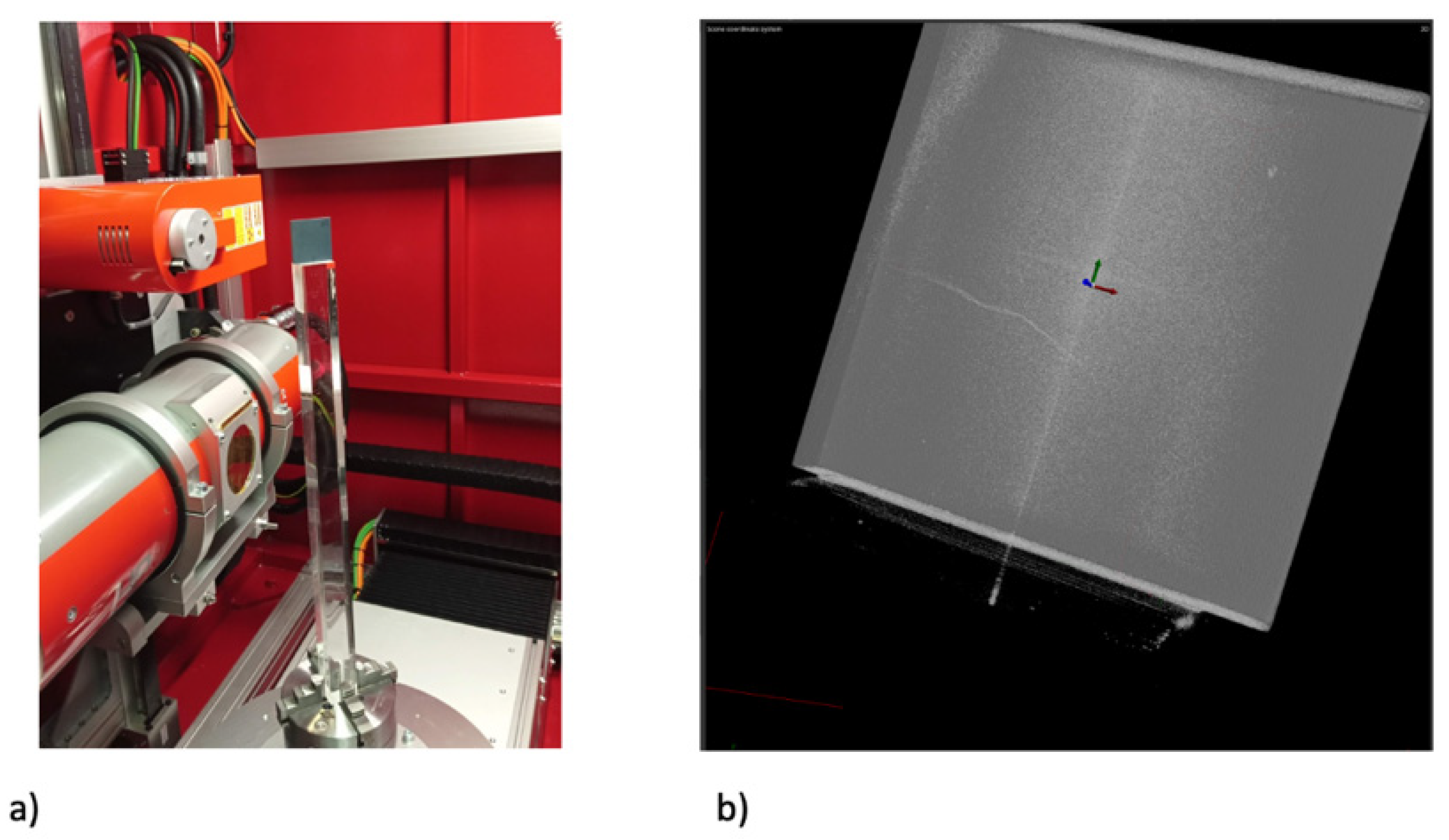
2.3. Post-Test Characterization

Slabs that had been exposed to accelerated ageing were examined by computed X-ray tomography (XCT), using a Zeiss Versa 510 X-ray microscope (22 µm/voxel resolution, 140 kV accelerating voltage, 10 W power, exposure of 14 s per projection with no binning, and 3001 projections per tomograph, Oberkochen, Germany). To reduce the scanning time, four samples exposed to the same thermal ageing conditions were examined simultaneously in a vertical stack with each sample in the horizontal plane. The tomographs were reconstructed by using the microscope software. For comparison, XCT examination of selected samples was also performed by using a Gilardoni high-energy system designed for industrial tomography (30 µm/voxel, 100 kV accelerating voltage, 28 W power, exposure of 2.5 s per projection with no binning, and 360 projections per tomograph, Mandello del Lario, Italy).
To verify the ability of XCT to detect cracking, a single slab of a similar (prototype) extruded SiC material (43% porosity, 50 × 50 × 5 mm) was observed by tomography at 20 µm/voxel (Zeiss Versa 510, 110 kV voltage, 10 W power, 6 s exposure time, 3001 projections over 360° rotation, and no binning, Oberkochen, Germany). The slab then received 10,000 cycles of thermal ageing (1 min/cycle) and was observed again, using the same microscope setup. Digital volume correlation (DVC) was then applied, using the LaVision DaVis software (sequential correlations with the minimum window size of 32 voxels, 75% overlap, Göttingen, Germany) to measure the relative 3D displacement fields. The correlation used the attenuation contrast from the internal porosity. An equivalent analysis of an identical slab, with a rigid body translation of 400 µm applied between tomographs that were obtained under the same conditions, demonstrated that DVC measured the local displacements with an uncertainty of 0.2 voxels (i.e., ~4 µm).
Ultrasound examination at 25 MHz with a Panametrics 5073PR system (Waltham, MA, USA) operating with immersion coupling at a focal length of 20 mm (6 mm probe diameter) was applied to selected slabs using an automated X-Y mapping system (step size 0.1 mm) developed at the ENEA, the National Agency for New Technologies, Energy and Sustainable Economic Development in Rome, Italy. This operates in the pulse-echo mode (Tektronics TDS 3032B, sampling rate 125 × 106 per second, Beaverton, Oregon, USA) to map the echo signal amplitude, which is dependent in the geometric size of defects. The three-dimensional amplitude matrix that is obtained can be represented by a point cloud for visualization.
Thermal diffusivity, α ( T ) (mm2/s), in the temperature range from 25 to 1000 °C was assessed through the Light Flash Analysis method (LFA) using a NETZSCH LFA 467 HT Hyperflash® (Selb, Germany). This employs a Xenon lamp (Selb, Germany) to provide the flash, and an infrared detector measures the temperature rise of the sample as a function of time. The thermal diffusivity, α ( T ) , was determined through the Parker method [28] that is based on the ratio between sample thickness and half-rise time (i.e., the time for the temperature of the rear surface of the sample to rise to half of the maximum temperature). The post-analysis was carried out through the improved Cape–Lehman approach [29,30] using the Proteus® Software (Selb, Germany), thus allowing two-dimensional heat flows, heat losses and radiation effects above 500 °C to be assessed. The specific heat, c p ( T ) , was evaluated indirectly by means of reference samples and the literature tables [31,32]. In particular, on the basis of specific heat values available in the literature [31], a reference sample was built for these analyses. Over the whole temperature range, the specific heat values were evaluated and assigned to a sample obtained from the first non-aged slab, which is the reference sample, as in Reference [32]. Thus, the thermal conductivity, K(T), was obtained via Equation (1), using the sample’s density, ρ ( T ) , which was determined by using the Archimedes method in deionized water.
K ( T ) = α ( T ) c p ( T ) ρ ( T )

3. Results

The experimental campaigns were conducted in order to compare the effect of different thermal-ageing conditions of the thermophysical properties of porous SiC samples. The test conditions were established by taking into account the realistic conditions of solar ageing, the possibilities provided by the facility and the temperatures of solar ageing campaigns that might be achieved in subsequent tests of SiC cups in a solar receiver. In particular, the cycles were conducted at three different speeds, in the temperature range between 300 and 800 °C, and at cycle speeds varying between 6 and 10 min/cycle in the temperature range between 300 and 1000 °C. The relevant thermal ageing parameters are listed in Table 2.

3.1. Microtomography Investigations

After performing the thermal ageing treatments, the slabs were observed by tomography to inspect for cracks. An example of a cracked specimen observed by high-resolution XCT (slab 21—see Table 2) is shown in Figure 3. The crack, clearly observed by XCT to be through the thickness, was barely visible by optical inspection (optical visibility was always better on the un-irradiated side, side 1, with no crack visible on the solar irradiated side, side 2, in most cases). Example data for a similar specimen (slab 23—see Table 1) undergoing ultrasonic inspection are shown in Figure 4a. Both the C-scan and D-scan (shown in Figure 4a,b, respectively) successfully detected the crack. The lower-resolution industrial tomography was also able to detect the crack successfully (Figure 5).
Tomography found cracks in the four of specimens, specimens 21 to 24, which experienced the highest surface temperature of 1000 °C. Two of specimens 17–20 had detectable cracks (slabs 17 and 18; there were no cracks seen in slabs 19 and 20); of the specimens that were exposed to a maximum temperature of 800 °C; these four specimens were heated at the highest rate and experienced a higher thermal gradient during heating than those that were heated at a lower rate (Table 2). Only one crack was observed in each damaged specimen, and there were no cracks observed in slabs 8 to 16. In each case, the crack propagated towards the center of the specimen from near the center of one edge. The DVC analysis of high-resolution XCT images, when applied to the thermally cycled prototype material (Figure 6), showed that this cracked in a similar manner to the production quality material. The crack opening displacement can be visualized as a nominal strain, which describes the local gradient of the displacement field.

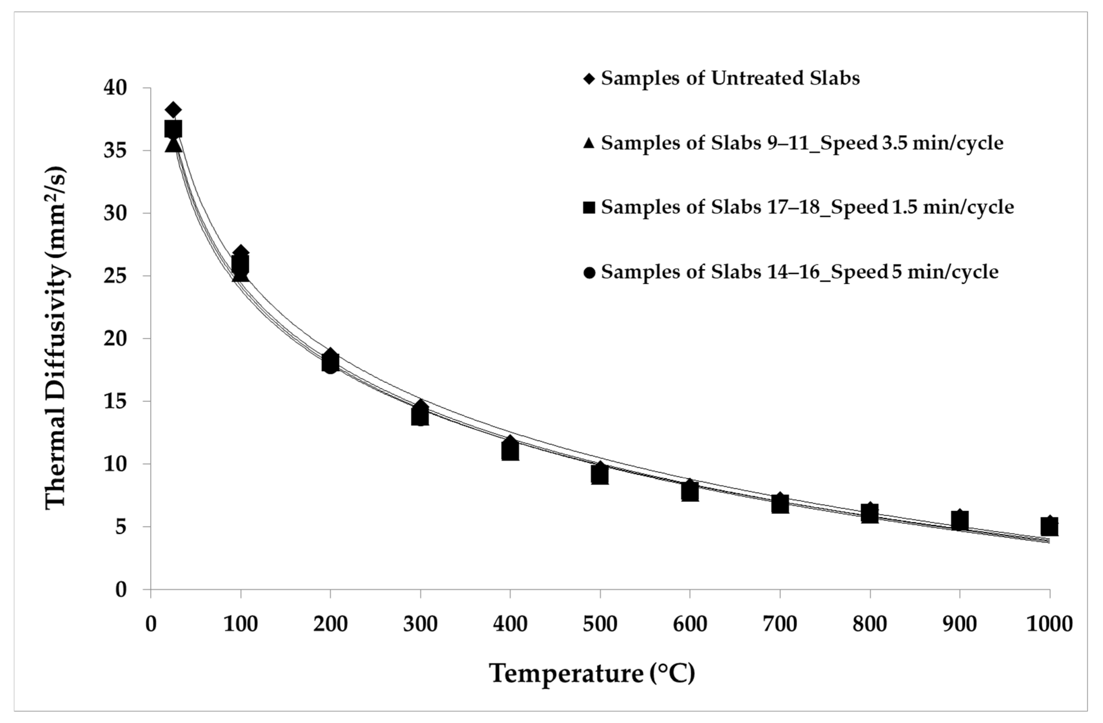
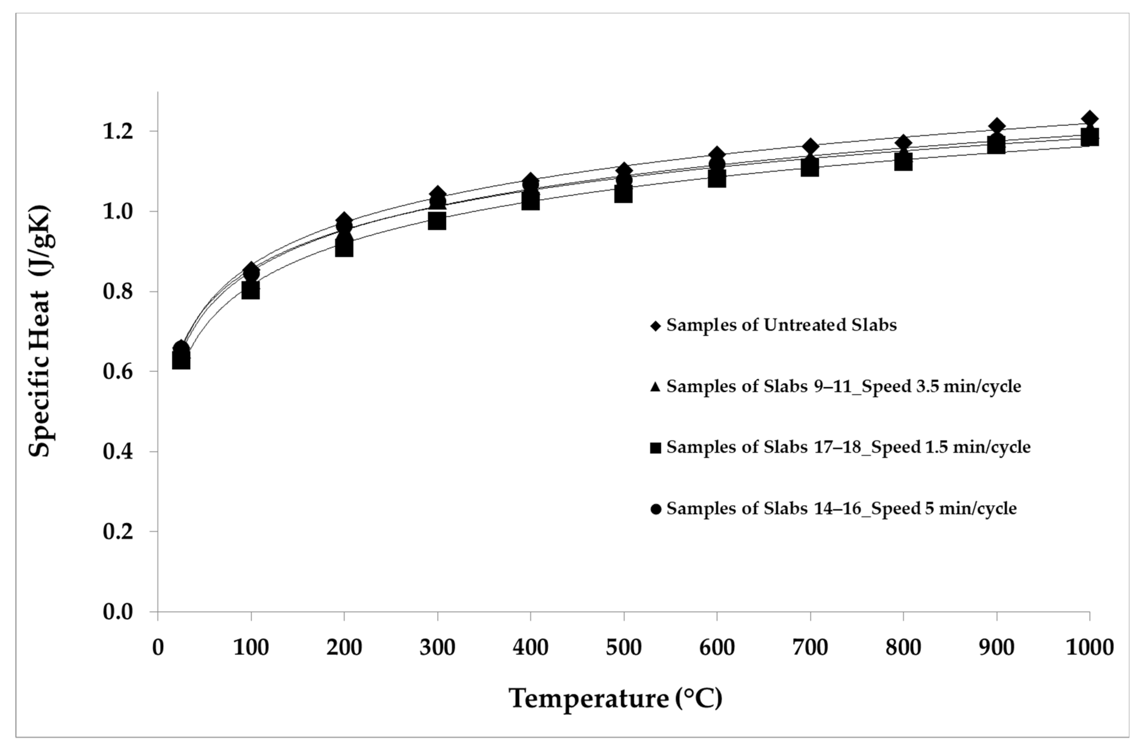
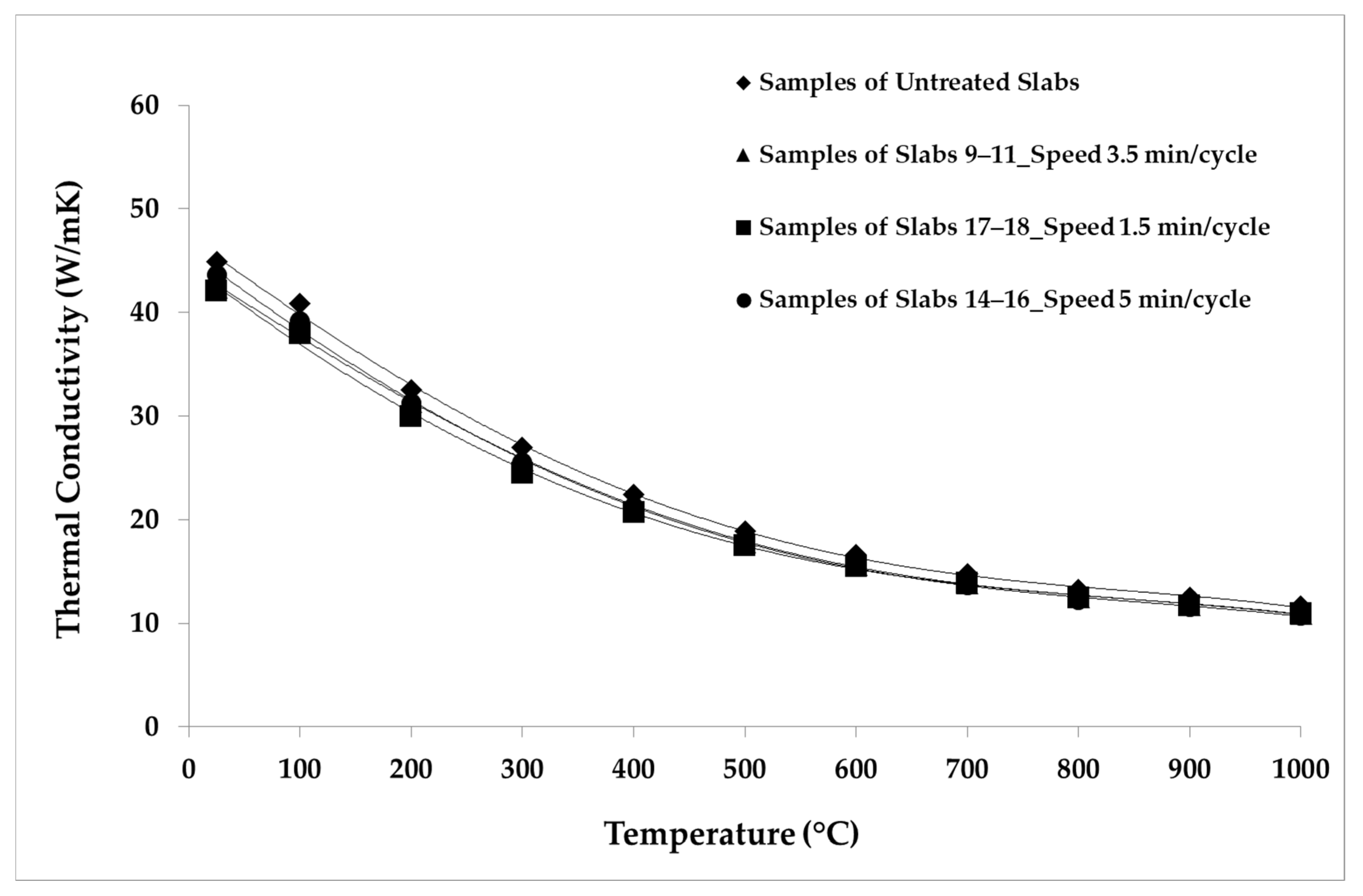
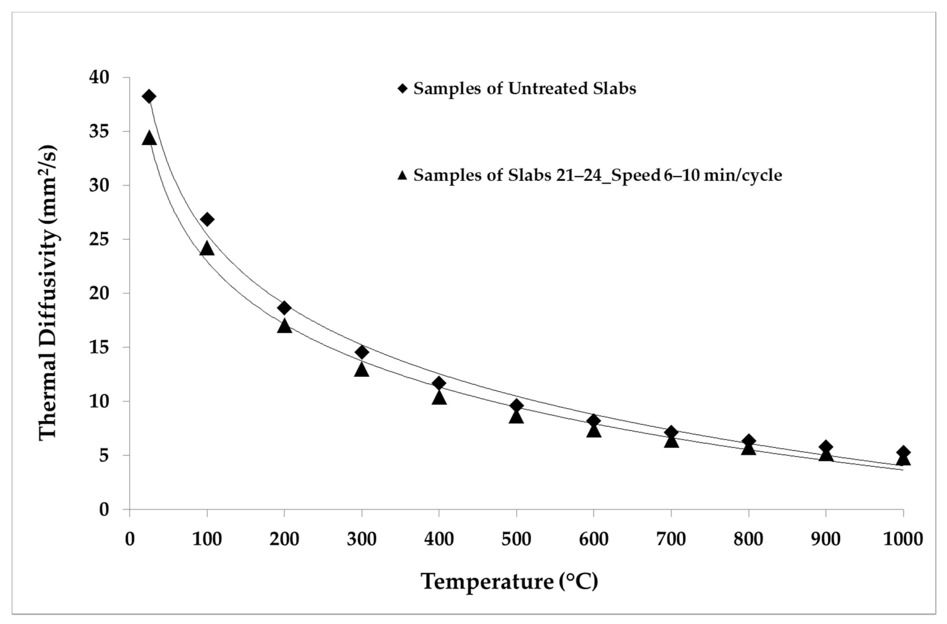
3.2. Thermophysical Characterizations

For the thermophysical characterization, circular samples were obtained by core drilling and subsequent machining from aged and non-aged slabs grouped according to Table 4. Figure 7 depicts an example of a sample. The tomography observations were used to avoid the detected cracks when preparing the thermophysical samples, which would otherwise be non-representative. The samples with the longest ageing cycles (5 min/cycle) were subjected to a lower temperature gradient than the samples subjected to the other thermal ageing conditions, and, significantly, the samples aged with slower cycles had no evident cracks. Two samples were analyzed for each group of slabs that represented the different ageing conditions. Table 4 summarizes the physical characteristics of the samples. Previous studies (see Reference [32] as an example) of the porous SiC analyzed in this paper found an average density of about 1800 kg/m3 and a deviation of ca. 2.8% (about 50 kg/m3) within the same production batch in the untreated condition. The variations of density for the individual samples in Table 4 are within this range and do not show an effect of ageing.
The LFA Method was employed for the thermal analysis of the samples. The parameters and the conditions of the analysis are shown in Table 5. The repeatability was verified by making five shots for each temperature point. The average values of the thermal properties measured for the samples belonging to each group of slabs are reported in Table 6, Table 7, Table 8, Table 9 and Table 10. The average values of the thermal properties of both the aged samples and the non-aged ones for each temperature point are also visualized in Figure 8, Figure 9, Figure 10, Figure 11, Figure 12 and Figure 13.
The specific heat of the samples increased with an increasing temperature (Figure 9). On the basis of specific heat values available in the literature [31], a reference sample was built for these analyses. Over the whole temperature range, the specific heat values were evaluated and assigned to a sample obtained from the first non-aged slab, which is the reference sample as given in Reference [32]. The specific heat of each of the other samples was assessed by comparing its temperature rise with that of the reference sample, as detailed in References [32,33]. The samples of groups 8–11 and 13–16, which were aged with longer cycles, showed a reduction in specific heat of about 2% compared to the non-aged samples, while the samples aged with shorter cycles presented an average reduction in specific heat of about 5%, which was particularly marked below 500 °C.
Figure 10 depicts the reduction in the thermal conductivity of the samples of groups 9–11 (3.5 min/cycle), 14–16 (5 min/cycle), and 17–18 (1.5 min/cycle) compared to the non-aged samples. The reduction was about 6% for the samples aged with longer cycles. The thermal conductivity of the samples aged with shorter cycles reduced by about 7% over the whole temperature range. The reduction in thermal conductivity is greater than the respective reductions in thermal diffusivity and specific heat, because conductivity is affected by both properties.
Figure 11, Figure 12 and Figure 13 show the comparison between the thermal diffusivity, specific heat and thermal conductivity of non-aged samples and of samples aged with longer cycles (speed 6–10 min/cycle), in the temperature range between 300 and 1000 °C. The thermophysical properties investigated were all reduced by about 10% over the whole temperature range with respect to the thermal properties of the non-aged samples, as shown below.

4. Discussion

The results show that the thermal ageing conditions of simulated solar cycles have an effect on the thermophysical properties of porous SiC slabs. Thermal diffusivity showed a decreasing trend with increasing temperature, due to the progressively higher phonon scattering [31,32]. For thermal cycles carried out in the same temperature range, i.e., between 300 and 800 °C, the thermal diffusivity of the aged samples decreased with the increasing speed of the ageing cycles. In particular, by comparing the samples of groups 9–11 (3.5 min/cycle), 14–16 (5 min/cycle), and 17–18 (1.5 min/cycle) with the non-aged (i.e., untreated) samples, it can be seen that thermal diffusivity reduced by about 6% in the whole temperature range for the samples with the longest ageing cycles, while diffusivity reduced by 5% for 3.5 min/cycle and by about 4% for 1.5 min/cycle. This confirms that the thermal diffusivity has been affected by thermal-ageing treatment.
By comparison between untreated and aged samples, it is also observed that, for samples aged over an inner temperature range from 300 to 800 °C, the specific heat was reduced by up to 5% in the samples aged with shorter cycles (Figure 9). This change is consistent with the literature findings, particularly those in Reference [34], where the specific heat of SiC and other materials was measured in order to understand the potential of each material to be used as a thermal energy storage medium in CSP plants; in that work, SiC showed a decrease in specific heat of about 8% after thermal ageing.
The observed change in thermal diffusivity and, hence, the thermal conductivity, is consistent with the literature findings of the effects of microcracking on thermal properties [35,36]. In particular, the study in Reference [36] shows that extensive microcracking in large-grain-sized materials (over 1 µm) significantly decreased thermal diffusivity. In this study, the mechanism for the decrease in thermal diffusivity is judged to be microcracking from thermal strains between the grains of the porous SiC. The mechanism for the observed reduction in specific heat after thermal ageing is not clear. Microcracking affects the porosity of the samples, but porosity has been shown to not significantly affect the specific heat, as reported in Reference [31], where the specific heat of porous SiC at different levels of porosity was determined.
The failure of porous materials due to very aggressive thermal ageing conditions has been reported in Reference [37]. In that work, it was concluded that the lack of formation of a protective oxide layer during ageing appeared to allow the fluxes to readily diffuse, due to the highly porous microstructure and the severe conditions of the thermal shock test. In this study, the shortest ageing cycles caused some slabs to crack. Samples tested over the larger temperature range of 300 to 1000 °C also cracked, despite the nominally lower thermal gradient. The cracks, which were detectable by non-destructive evaluation via X-ray tomography and ultrasound imaging, were optically visible on the back face of samples that was not irradiated by the solar flux. The fracture initiated near the middle of the sample edge and propagated towards the center. The initiation site is the expected location of maximum thermal stress in an unconstrained and simply supported rectangular slab that is heated uniformly on one planar surface [38]; hence, the thermal strains from higher thermal gradients encourage cracking. There is some inhomogeneity also of the surface temperature, as indicated in Figure 3, which would also contribute to thermal strains. It is also possible that cracking could be initiated if the thermal expansion of the slabs is restricted by the sample supports. Significantly, inspection by XCT or ultrasound allowed these cracks to be identified, and avoided, for the preparation of valid samples for the measurement of thermophysical properties.
This work has informed the CEN CWA High temperature accelerated ageing of ceramic specimens and small solar receivers under concentrated solar radiation, which describes the requirements that apply to the test pieces (shape and dimensions) and also to the test platform, in terms of suitability for supporting and holding the samples (position, freedom for thermal expansion, and compatibility between materials). It also includes guidance for the ageing procedure, with regard to the flux shape, the heating and cooling rates, the number of cycles and the temperature and incident flux measurement, and the analysis of tested samples. The thermophysical characterization conducted on these ceramic materials, which are to be employed in next-generation solar receivers, has laid the basis for the proposal of an informative Annex to ISO 18755, which is currently being developed in order to allow the complete characterization of ceramic materials by means of the flash method. The data from this thermophysical characterization may be used in numerical models to predict the thermal stresses in the cups that constitute the solar thermal receiver, in order to predict possible failure points. Accurate data for the bulk materials—in particular, their mechanical behavior—will enable prediction of the lifetime of the solar receivers.

5. Conclusions

Thermal ageing of porous (43% porosity) silicon carbide slabs with simulated solar cycles in a solar furnace was used to investigate the change in thermophysical properties. Macroscopic thermal strains caused fracturing in the slabs aged with shorter cycles and higher temperatures. These cracks were difficult to resolve visually, but could be identified reliably by using inspection by computed X-ray tomography and ultrasonic inspection, which allowed the preparation of valid specimens for the measurement of thermal properties. The thermophysical analyses showed a decrease in thermal diffusivity of up to 6%, with a greater decrease for shorter cycles over the same inner temperature range. This phenomenon may be explained by the development of micro-cracking, due to thermal strains between the grains of the porous SiC.

Author Contributions

Investigation, I.C., G.D.A., J.F., Y.C., A.T. and C.T.; resources, V.M.C.; writing—original draft preparation, G.D.A. and T.J.M.; writing—review and editing, I.C., V.M.C., G.D.A., L.L., S.C.-L., T.J.M. and A.M.S.; project administration, L.L. and A.R.; funding acquisition, A.R. All authors have read and agreed to the published version of the manuscript.

Funding

This project has received funding from the European Union’s Horizon 2020 Research and Innovation Programme, under grant agreement no. 721045. The Xradia 510 microscope was funded by University of Oxford experimental equipment grant from the UK Engineering and Physical Sciences Research Council (EPSRC) (EP/M020833X/1). The paper reflects only the authors’ views and the European Commission is not responsible for any use that may be made of the information it contains.

Institutional Review Board Statement

Not applicable.

Informed Consent Statement

Not applicable.

Data Availability Statement

The data presented in this study are available upon request from the corresponding author. The data are not publicly available, due to the use of proprietary manufacturing processes.

Conflicts of Interest

The authors declare no conflict of interest. The funders had no role in the design of the study; in the collection, analyses, or interpretation of data; in the writing of the manuscript; or in the decision to publish the results.

References

  1. Aprà, F.M.; Smit, S.; Sterling, R.; Loureiro, T. Overview of the Enablers and Barriers for a Wider Deployment of CSP Tower Technology in Europe. Clean Technol. 2021, 3, 377–394. [Google Scholar] [CrossRef]
  2. OECD. Technology Roadmap: Concentrating Solar Power; OECD: Paris, France, 2010. [Google Scholar]
  3. Capuano, R.; Fend, T.; Schwarzbözl, P.; Smirnova, O.; Stadler, H.; Hoffschmidt, B.; Pitz-Paal, R. Numerical models of advanced ceramic absorbers for volumetric solar receivers. Renew. Sustain. Energy Rev. 2016, 58, 656–665. [Google Scholar] [CrossRef]
  4. Avila-Marin, A.L. Volumetric receivers in Solar Thermal Power Plants with Central Receiver System technology: A review. Solar Energy 2011, 85, 891–910. [Google Scholar] [CrossRef]
  5. Rajendran, D.R.; Ganapathy Sundaram, E.; Jawahar, P. Review on influencing parameters in the performance of concentrated solar power collector based on materials, heat transfer fluids and design. J. Anal. Calorim. 2020, 140, 33–51. [Google Scholar] [CrossRef]
  6. Clifford, K.H. Advances in central receivers for concentrating solar applications. Sol. Energy 2017, 152, 38–56. [Google Scholar] [CrossRef]
  7. Schmitz-Goeb, M.; Finker, A. PHOEBUS Power Tower Processes with the open Volumetric Air Receiver. In Solar Thermal Concentrating Technologies; C.F. Müller Verlag: Heidelberg, Germany, 1997. [Google Scholar]
  8. Keintzel, G.; Schmitz-Goeb, M. The Phoebus Solar Power Tower. In Proceedings of the 1997 ASME International Solar Energy Conference, Washington, DC, USA, 27–30 April 1997; pp. 47–53. [Google Scholar]
  9. Tellez, F.; Romero, M.; Heller, P.; Valverde, A.; Dibowski, G.; Ulmer, S. Thermal Performance of SolAir 3000 kWth Ceramic Volumetric Solar Receiver, 12th International Symposium Solar Power and Chemical Energy Systems; Instituo de Investigaciones Electricas: Oxaca, Mexico, 2004. [Google Scholar]
  10. Téllez Sufrategui, F.M. Thermal Performance Evaluation of the 200 kWth “SolAir” Volumetric Solar Receiver; Informes Técnicos Ciemat: Madrid, Spain, 2003; pp. 1–52. [Google Scholar]
  11. Liu, W.; Wei, G.; Huang, P.; Chao, X.C.; Du, X. Design and performance analysis of volumetric solar receiver based on porous foam ceramics. AIP Conf. Proc. 2018, 2033, 1–8. [Google Scholar] [CrossRef]
  12. CIEMAT; PSA. Plataforma Solar de Almeria, Annual Report. 2004. Available online: https://www.psa.es/en/techrep/2004/ATR2004_ing.pdf (accessed on 25 July 2021).
  13. Oller, I. Solar Facilities for the European Research Area, SFERA Project, Final Report. 2016, pp. 1–45. Available online: https://cordis.europa.eu/docs/results/228/228296/final1-sfera-final-report.pdf (accessed on 25 July 2021).
  14. Köhl, M.; Köhl, M.; Jorgensen, G. Performance and Durability Assessment: Optical Materials for Solar Thermal Systems, 1st ed.; Elsevier Science: Amsterdam, The Netherlands, 2004; pp. 4–5. [Google Scholar]
  15. Pettit, R.B. Accelerated temperature aging of black chrome Solar selective coatings. Sol. Energy Mater. 1983, 8, 349–361. [Google Scholar] [CrossRef]
  16. Sallaberry, F.; García de Jalón, A.; Zaversky, F.; Vázquez, A.J.; López-Delgado, A.; Tamayo, A.; Mazo, M.A. Towards Standard Testing Materials for High Temperature Solar Receivers. Energy Procedia 2015, 69, 532–542. [Google Scholar] [CrossRef] [Green Version]
  17. Setien, E.; Fernández-Reche, J.; Ariza-Camacho, M.J.; Álvarez-de-Lara, M. Solar aging of receivers made of nickel super alloys. AIP Conf. Proc. 2018, 2033, 230012. [Google Scholar] [CrossRef]
  18. Pritzkow, W. Pressure loaded volumetric ceramic receiver. Sol. Energy Mater. 1991, 24, 498–507. [Google Scholar] [CrossRef]
  19. Boubault, A.; Claudet, B.; Faugeroux, O.; Olalde, G. Aging of solar absorber materials under highly concentrated solar fluxes. Sol. Energy Mater. Sol. Cells 2014, 123, 211–219. [Google Scholar] [CrossRef]
  20. Mey-Cloutier, S.; Caliot, C.; Kribus, A.; Gray, Y.; Flamant, G. Experimental study of ceramic foams used as high temperature volumetric solar absorber. Sol. Energy 2016, 136, 226–235. [Google Scholar]
  21. Oliveira, F.A.C.; Fernandes, J.C.; Galindo, J.; Rodríguez, J.; Cañadas, I.; Rosa, L.G. Thermal resistance of solar volumetric absorbers made of mullite, brown alumina and ceria foams under concentrated solar radiation. Sol. Energy Mater. Sol. Cells 2019, 194, 121–129. [Google Scholar] [CrossRef] [Green Version]
  22. Xu, K.; Du, M.; Hao, L.; Mi, J.; Yu, Q.; Li, S. A review of high-temperature selective absorbing coatings for solar thermal applications. J. Mater. 2020, 6, 167–182. [Google Scholar] [CrossRef]
  23. Li, S.; Wei, C.; Zhou, L.; Wang, P.; Xie, Z. Evaporation-condensation derived silicon carbide membrane from silicon carbide particles with different sizes. J. Eur. Ceram. Soc. 2019, 39, 1781–1787. [Google Scholar] [CrossRef]
  24. Bukhari, S.Z.A.; Ha, J.H.; Lee, J.; Song, I.H. Fabrication and optimization of a clay-bonded SiC flat tubular membrane support for microfiltration applications. Ceram. Int. 2017, 43, 7736–7742. [Google Scholar] [CrossRef]
  25. Eray, E.; Candelario, V.M.; Boffa, V.; Safafar, H.; Østedgaard-Munck, D.N.; Zahrtmann, N.; Kadrispahic, H.; Jørgensen, M.K. A roadmap for the development and applications of silicon carbide membranes for liquid filtration: Recent advancements, challenges, and perspectives. Chem. Eng. J. 2021, 414, 128826. [Google Scholar] [CrossRef]
  26. Eray, E.; Boffa, V.; Jørgensen, M.K.; Magnacca, G.; Candelario, V.M. Enhanced fabrication of silicon carbide membranes for wastewater treatment: From laboratory to industrial scale. J. Memb. Sci. 2020, 606, 118080. [Google Scholar] [CrossRef]
  27. Rodríguez, J.; Cañadas, I.; Zarza, E. New PSA High Concentration Solar Furnace SF40. AIP Conf. Proc. 2016, 1734, 070028. [Google Scholar] [CrossRef] [Green Version]
  28. Parker, W.J.; Jenkins, R.J.; Butler, C.P.; Abbott, G.L. Method of Determining Thermal Diffusivity, Heat Capacity and Thermal Conductivity. J. Appl. Phys. 1961, 32, 1679. [Google Scholar] [CrossRef]
  29. Cape, J.; Lehman, G. Temperature and Finite Pulse-time effect in the flash method for measuring thermal diffusivity. J. Appl. Phys. 1963, 34, 1909–1913. [Google Scholar] [CrossRef]
  30. Josell, D.; Warren, J.; Cezairlyian, A. Correcting an error in Cape-Lehman’s analysis for determining thermal diffusivity from thermal pulse experiments. J. Appl. Phys. 1995, 78, 6867–6869. [Google Scholar] [CrossRef]
  31. Jang, B.K.; Sakka, Y. Thermophysical properties of porous SiC ceramics fabricated by pressureless sintering. Sci. Technol. Adv. Mater. 2007, 8, 655–659. [Google Scholar] [CrossRef]
  32. Laghi, L.; De Aloysio, G.; Candelario, V.M.; Kadrispahic, H.; Gianella, S.; Rinaldi, A. Thermophysical Characterization of Ceramic Materials for Next-Generation Solar Receivers. In Proceedings of the 2020 IEEE International Conference on Environment and Electrical Engineering and 2020 IEEE Industrial and Commercial Power Systems Europe (EEEIC /I&CPS Europe), Madrid, Spain, 9–12 June 2020; pp. 1–6. [Google Scholar] [CrossRef]
  33. NETZSCH. Laser Flash Analysis, PDF Document. Available online: http://jeinet.jnsp.re.kr/file/public/public_201611120451365611.pdf (accessed on 1 April 2020).
  34. Díaz-Heras, M.; Calderon, A.; Navarro, M.; Almendros-Ibañez, J.A.; Fernandez, A.I.; Barreneche, C. Characterization and testing of solid particles to be used in CSP plants: Ageing and fluidization tests. Sol. Energy Mater. Sol. Cells 2021, 219, 110793. [Google Scholar] [CrossRef]
  35. Siebeneck, H.J.; Hasselman, D.P.H.; Cleveland, J.J.; Bradt, R.C. Effect of Microcracking on Thermal Diffusivity of Fe2TiO5. J. Am. Ceram. Soc. 1976, 59, 241–244. [Google Scholar] [CrossRef]
  36. Hasselman, D.P.H. Effect of Cracks on Thermal Conductivity. J. Compos. Mater. 1978, 12, 403–407. [Google Scholar] [CrossRef]
  37. Mazo, A.; Padilla, I.; Lopez-Delgado, A.; Tamayo, A.; Rubio, J. Silicon Oxycarbide and Silicon Oxycarbonitride Materials under Concentrated Solar Radiation. Materials 2021, 14, 1013. [Google Scholar] [CrossRef]
  38. Randall, F.; Brian, R. Barron. In Design for Thermal Stresses; John Wiley & Sons: Hoboken, NJ, USA, 2011; Chapter 7; pp. 277–283. [Google Scholar]
Figure 1. Schematic diagram of the solar ageing test bench in a horizontal solar furnace facility.
Materials 14 04627 g001
Figure 2. (a) Samples (50 mm × 50 mm × 5 mm) placed in horizontal position on the test bench before solar ageing testing. (b) Accelerated ageing test bench on test at SF40. (c) Slabs with thermocouples observed under concentrated solar radiation during solar ageing tests.
Materials 14 04627 g002
Figure 3. (a) µXCT cross-section of a slab (slab 21—see Table 2). A through thickness crack propagates from near the center of one edge, reaching the center of the slab. The “ring” contrast is an image artefact. (b) Optical images of the two surfaces of the slab. The crack is slightly visible on side 1 (unirradiated) and barely visible on side 2 (solar irradiated). All images show the full 50 mm × 50 mm slab.
Materials 14 04627 g003
Figure 4. Ultrasonic inspection: (a) specimen (slab 23—see Table 2) undergoing ultrasonic mapping in pulse-echo mode, (b) amplitude map in C-scan model, and (c) amplitude map in D-scan mode. All images show the full 50 mm × 50 mm slab.
Materials 14 04627 g004
Figure 5. Industrial tomography (Gilardoni): (a) specimen (slab 23) within the tomography system; (b) 3D visualization within the full slab of crack, which propagates from the middle of the left edge towards the center. All images show the full 50 mm × 50 mm slab.
Materials 14 04627 g005
Figure 6. Characterization of solar aged prototype material: (a) optical image (in solar furnace) after 10,000 cycles; (b) XCT images (cropped) at the same midsection plane before and after solar ageing, with cross-section of the developed crack; (c) visualization of the crack, using the nominal strain in the x-direction, due to the relative displacements measured by digital volume correlation between tomographs.
Materials 14 04627 g006
Figure 7. Example of the thermophysical sample (12.7 mm diameter and 5 mm thickness).
Materials 14 04627 g007
Figure 8. Thermal diffusivity values considering different speed of thermal cycles.
Materials 14 04627 g008
Figure 9. Specific heat values considering different speed of thermal cycles.
Materials 14 04627 g009
Figure 10. Thermal conductivity average values considering different speed of thermal cycles.
Materials 14 04627 g010
Figure 11. Thermal diffusivity values of untreated samples and samples aged in the temperature range 300–1000 °C.
Materials 14 04627 g011
Figure 12. Specific heat values of untreated samples and samples aged in the temperature range 300–1000 °C.
Materials 14 04627 g012
Figure 13. Thermal conductivity values of untreated samples and samples aged in the temperature range 300–1000 °C.
Materials 14 04627 g013
Table 1. Selected test methods for materials or components tested in point focus facilities and resistively heat laboratory tube furnaces.
Material or
Component Tested
Project/
Receiver
FacilityConditionsVariables MeasuredReference
RESISTIVELY HEAT LABORATORY TUBE FURNACES
Nickel Substrates for Coatings Plated from Four Different Bath CompositionsSandia National
Laboratories
DE-AC04-76-DP00789.
Resistively heat laboratory tube furnaces - SandiaTemperature range: 350 to 450 °C
aging time: 100 h–5000 h.
Optical properties: solar absorptance and emittancePettit, R. B. 1983 [15]
SiC
(Laboratory Prepared Materials)
MirasolResistively tubular furnaceT: 1000 °C for 0 and 600 s.
Cycles: 1, 2, 5 and 10 high temperature cycles
Reflectance valuesSallaberry, F. et al., 2015 [16]
FRESNEL LENS
Metallic Samples
(Iron Aluminides).
Silicon Oxicarbides
MirasolFresnel lenses:
un-mounted in CENER, and on solar tracker in CSIC-CENIM
Heating rates:
- Ambient to 800 °C: 50–70 °C/s.
- 800 to 1000 °C: 3–5 °C/s.
Cooling rates:
- 1000 to 600 °C: 9–11 °C/s.
- 600–400 °C: 2–4 °C/s
- 400–200 °C: 1 °C/s.
Optical and mechanical properties, such as optical and scanning electron microscopySallaberry, F. et al., 2015 [16]
PARABOLIC DISHES
INCONEL 625SFERA IICIEMAT-PSA DISTALAging temperature: 700 °C
Period: up to 500 h.
Samples: 5 tubular samples
Evolution of microstructure and mechanical properties: SEM, optical microscopy. Vickers hardnessSetien, E.; et al., 2017 [17]
SOLAR FURNACES
SIRCON
foam absorber made of SIRCON (Si3N4)
PLVCR-5Sandia (SNLA)
Solar furnace
T average outlet air: 625 °C
T max outlet air: up to 1000 °C
Power: 5 kW
P 10 bar
Flux_max level: 2 MW/m2
Testing in solar conditionsPritzkow, W. 1991 [18]
INCONEL with Pyromak 2500 layerPROMES-CNRSPROMES-CNRS
SAAF
Samples: 1 mm Inconel (after spray-gun application of paint coating).
Mean irradiance: 104 kW/m2–173 kW/m2, 346 kW/m2
Period: 10 s, 30 s,
Exposure time: 1000 s, 3000 s
Normal solar absorptance, thermal effusivity
Thermal conductivity,
thermal contact resistance between coating and substrate.
Boubault A., et al., 2014 [19]
Ceramic foams (SiC and ZrB2) as high temperature volumetric solar absorberOPTISOL project,
SFERA project,
and STAGE-STE
PROMES-CNRS
6 kW solar furnace.
Kaleidoscope solar flux homogenizer
Tout: 833 to 998 °C
Mass flow rate: 1 g/s.
α-SiC, Si-SiC, SiC, SiC + Al2O3, SiC + SiO2 + Al2O3, ZrB2.
SiC range of porosity (72–92%)
Calorimetry and fluxmetryMey-Cloutier, S. et al., 2016 [20]
MulliteSTAGE-STE.
SFERA II
H2CORK
project
CIEMAT-PSA
SF40
Tmax: average value of
1180 ± 35 °C
T differences ranging
- 200 °C (700–900 °C);
- 400 °C (700–1100 °C)
- 600 °C (700–1300 °C)
Mechanical properties: Typical strength versus strain
microscopic techniques (SEM and optical microscopy).
Oliveira, F.A.C., et al., 2019 [21]
Table 2. Parameters of the experimental ageing test conditions.
Group of SlabsNumber of CyclesInner Temperature Range (°C)Periods (min/Cycle)Thermal Gradient Max (°C/mm)Tmax Surface (°C)Flux -Normalized at 1000 W/m2 Insolation (W/cm2)
Slabs 17, 18, 19, 20500300–8001.5≅20–24860–92069–72
Slabs 8, 9 10, 11500300–8003.5≅22850–90040–42
Slabs 13, 14, 15, 16500300–8005≅10–13840–88042–44
Slabs 21, 22, 23, 24500300–10006–10≅10–141000–105047–55
Table 3. Average values of heating and cooling rates during the solar ageing tests.
Group of SlabsNumber of CyclesInner T Range (°C)Periods (min/Cycle)Heating Rate Average Values (°C/s)Cooling Rate Average Values (°C/s)Max Heating Rate (°C/s)Max Cooling Rate (°C/s)
Slabs 17, 18, 19, 20500300–8001.522.57.05030
Slabs 8, 9 10, 11500300–8003.56.53.02016
Slabs 13, 14, 15, 16500300–8005.05.02.51611
Slabs 21, 22, 23, 24500300–10006.04.05.01030
10.02.03.0630
Table 4. Physical characteristics of the samples (all diameter 12.7 mm).
Group of SlabsSampleThickness (mm)Density (kg/m3)
Untreated slabsSample from slab 15.8081780
Sample from slab 25.7141783
Group 8–11Sample 1 from slab 95.6481849
Sample 2 from slab 116.0141788
Group 13–16Sample 1 from slab 145.6621836
Sample 2 from slab 165.7281809
Group 17–20Sample 1 from slab 175.7071836
Sample 2 from slab 185.6741817
Group 21–24Sample 1 from slab 215.7741777
Sample 2 from slab 245.5701819
Table 5. Parameters and conditions of the thermophysical characterization carried out through the Light Flash Apparatus.
Temperature Range (°C)Temperature Steps (°C)Inert AtmosphereHeating Rate (K/min)
25–1000 °C100-(11 experimental points)Argon4
Table 6. Thermophysical properties of the untreated samples. Average values of the two samples.
Temperature (°C)Thermal Diffusivity (mm2/s)Specific Heat (J/gK)Thermal Conductivity (W/mK)
2538.2260.66044.895
10026.8610.85440.843
20018.6590.97932.532
30014.5281.04426.998
40011.6921.07722.416
5009.5971.10318.853
6008.1881.14216.659
7007.1481.16214.795
8006.3571.17313.275
9005.7751.21412.481
10005.2931.23211.613
Table 7. Thermophysical properties of the aged samples obtained from slabs 9 and 11. Average values of the two samples.
Temperature (°C)Thermal Diffusivity (mm2/s)Specific Heat (J/gK)Thermal Conductivity (W/mK)
2535.6000.65542.454
10025.2270.82938.050
20018.1250.95231.359
30013.7731.02825.724
40011.0071.06421.294
5009.1001.08017.878
6007.7491.11315.682
7006.7691.13113.925
8006.0141.14712.549
9005.4561.18411.744
10004.9931.20510.944
Table 8. Thermophysical properties of the aged samples obtained from slabs 14 and 16. Average values of the two samples.
Temperature (°C)Thermal Diffusivity (mm2/s)Specific Heat (J/gK)Thermal Conductivity (W/mK)
2536.4780.65743.605
10025.4760.84639.191
20017.8090.96331.239
30013.6631.02625.508
40010.9131.06821.240
5009.0361.07817.746
6007.7031.11915.707
7006.7191.11813.690
8005.9671.12712.258
9005.4071.17711.592
10004.9621.18810.742
Table 9. Thermophysical properties of the aged samples obtained from slabs 17 and 18. Average values of the two samples.
Temperature (°C)Thermal Diffusivity (mm2/s)Specific Heat (J/gK)Thermal Conductivity (W/mK)
2536.7240.62742.093
10025.8980.80237.944
20018.0590.90829.959
30013.7550.97524.496
40011.0531.02420.679
5009.1941.04317.512
6007.8451.08215.499
7006.8431.10813.851
8006.0841.12412.488
9005.5161.16511.735
10005.0471.18610.928
Table 10. Thermophysical properties of the aged samples obtained from slabs 21 and 24. Average values of the two samples.
Temperature (°C)Thermal Diffusivity (mm2/s)Specific Heat (J/gK)Thermal Conductivity (W/mK)
2534.4260.65640.427
10024.2450.83336.156
20017.0320.95629.154
30013.0321.02123.856
40010.4381.06619.952
5008.6721.08816.919
6007.4081.12114.893
7006.4611.14313.243
8005.7541.16612.035
9005.1971.19911.178
10004.7951.22110.500
Publisher’s Note: MDPI stays neutral with regard to jurisdictional claims in published maps and institutional affiliations.

