1. Introduction
The conventional production of fiber-reinforced ceramic components mainly takes place via polymer infiltration pyrolysis (PIP), melt infiltration process (MI), chemical vapor infiltration (CVI) or sintering processes [
1,
2,
3,
4,
5,
6,
7,
8,
9]. Another method that is still being researched on a small laboratory scale is electrophoresis deposition [
10]. In the following, these methods will be briefly described, and their advantages and disadvantages will be mentioned.
In the case of the PIP, a fiber preform is produced as the starting framework, e.g., made of carbon fibers. This is infiltrated with a matrix polymer in a temperature range between 150 and 300 °C, followed by the chemical crosslinking of the polymer. The resulting green body is referred to as carbon fiber-reinforced polymer (CFRP). By means of pyrolysis under inert conditions from 700 up to 1600 °C, a ceramic matrix composite (CMC) arises from the CFRP. Due to the volume shrinkage, which occurs during pyrolysis, the matrix is being pervaded by pores and cracks. By the repetition of the process, steps of pure filtration, crosslinking and pyrolysis several times, the resulting porosity can be reduced iteratively to a minimum. In the end, however, a low remaining porosity must be tolerated. The advantages and disadvantages of the PIP and other methods are summarized in
Table 1.
The MI process is similar to the PIP process but enables the production of CMCs with a higher density. In this case, the PIP process is interrupted after the first pyrolysis. Instead of repeating the previous process steps, the remaining void is infiltrated with metal instead (for example, liquid silicon infiltration (LSI)). This process adaption enables the reduction of porosity. The infiltrated metal closes the pores. In order to avoid the damage of the fibers by metal, the infiltration process must be carried out as quickly as possible.
The third conventional method is the CVI. Again, the basis is a fiber braid stabilized near the final contour. The fiber preform is heated in an oven and then flushed by the process gas. The process gas reacts, and some of the reaction products deposit on the fibers and form the matrix of the CMC. The remaining reaction products are filtered out of the process chamber.
Another variant for the production of oxidic CMC is sintering for matrix generation. Here, the matrix material is produced from starting materials by high-temperature treatment. These matrix precursor materials have lower melting temperatures (1000 to 1200 °C) than the final matrix (about 1600 °C). This allows processing without damaging the oxidic fibers by too high temperatures during processing. The matrix material is milled to powders in the nanometer particle size range and then processed into suspensions. The slurries are introduced between the fibers and sintered at the sintering temperature with high volume shrinkage.
Another method for matrix generation of CMC that is not yet conventionally used is electrophoresis. This involves dispersing electrically charged ceramic matrix particles in a liquid. The matrix particles are then deposited on oppositely charged fiber surfaces and between the fibers (electrodes) in a direct current electric field. The spaces between the fibers are filled with matrix material until the capillaries between the fibers are closed so far that the charged particles can no longer infiltrate. Here too, pore space remains open. In the experiments presented below, a CMC is to be produced for the first time using laser technology (Coherent Diamond J-3 10.6 400 W OEM laser, Coherent, Palo Alto, CA, USA) and a computer-controlled laydown mechanism (Axial Ingenieurgesellschaft GmbH, Dresden, Germany). For this purpose, samples of the powder materials SiO
2 and Y
2O
3 are first pressed and then melted by the laser. The SiC fiber material mixed into these samples as particles are given special consideration in the subsequent ceramography. It should not melt under the determined process parameters in order to avoid mixing with the matrix material and thus guarantee the typical CMC properties. The Y-Si-O matrix system was selected because it forms yttrium silicates in thermodynamic equilibrium, which have sufficient mechanical stability and excellent corrosion stability at both room and high temperatures [
11,
12,
13]. Likewise, the coefficient of thermal expansion is close to that of SiC fibers, and there are no chemical interactions between the components [
14,
15].
2. Materials and Methods
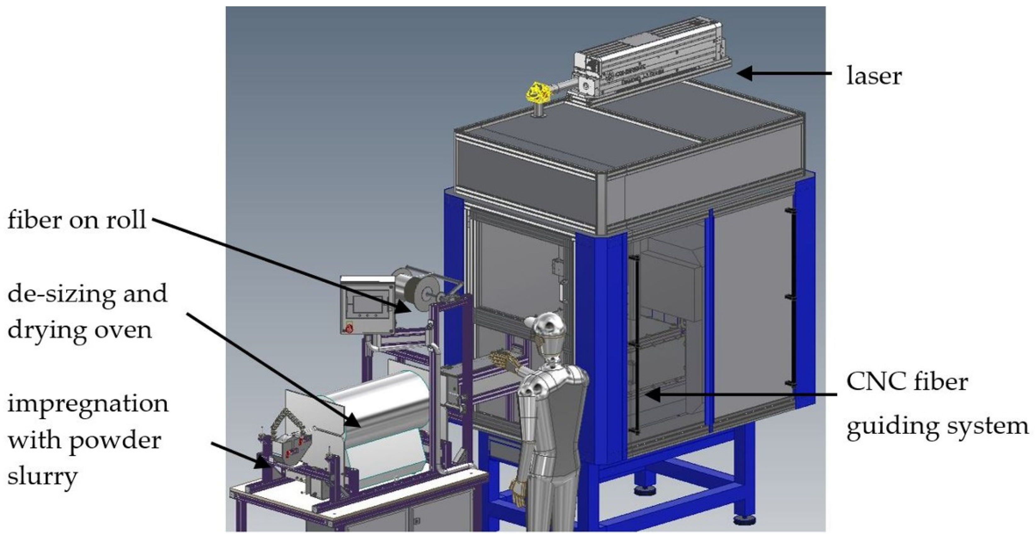
A new process based on additive manufacturing methods, as published in the patent specification DE102015205595B3 [
16], gives the opportunity to overcome long processing times and the dependency on furnace technology. A ceramic fiber bundle is to be continuously de-sized after unwinding from the fiber supply roll and then infiltrated with a ceramic slurry. Followed by a drying process, the infiltrated fiber bundle is positioned by a CNC-controlled depositing mechanism, and at the same time, the matrix material around the fibers is consolidated by means of laser treatment.
Compared to conventional methods, the new additive process offers various advantages (see
Table 1). One of them is shaping. This is to take place via a quasi-continuous process step. As described in the patent, a fiber bundle is to be infiltrated with matrix material and then deposited. The aim is to melt the matrix powder during the depositing process and to compact it around the fibers without damaging them. Since the requirements for the matrix starting materials are lower than for sintering, they are currently cheaper to procure. The new method should make it possible to integrate metallic fastening elements and sensor technology during the process through shorter, local energy input in the manufacturing process. Joining is addressed as a further possible application of the process. The process can theoretically be scaled well, as the machining area of the unit is regarded as the limit and can be adapted to the necessary conditions.
The fiber material, SiC, was defined as the base point for the material system. The following conditions for the matrix system and the beam source to be used are derived from this:
Comparatively high beam absorption of the matrix compared to the fiber material [
17]
Meltability of the matrix material
Physical and chemical compatibility with SiC (coefficient of linear thermal expansion, chemical interactions, oxidation).
As can be seen from sources [
13,
14], yttrium disilicate (Y
2Si
2O
7) seems to be suitable as a matrix material. However, the absorption values are not described. Based on other oxides [
17], however, it seems reasonable to expect that equally high absorption values can be achieved here for CO
2 lasers (λ = 10.6 μm). The higher absorption of the matrix materials should ensure that they melt before the fiber material with the lower absorption value is affected.
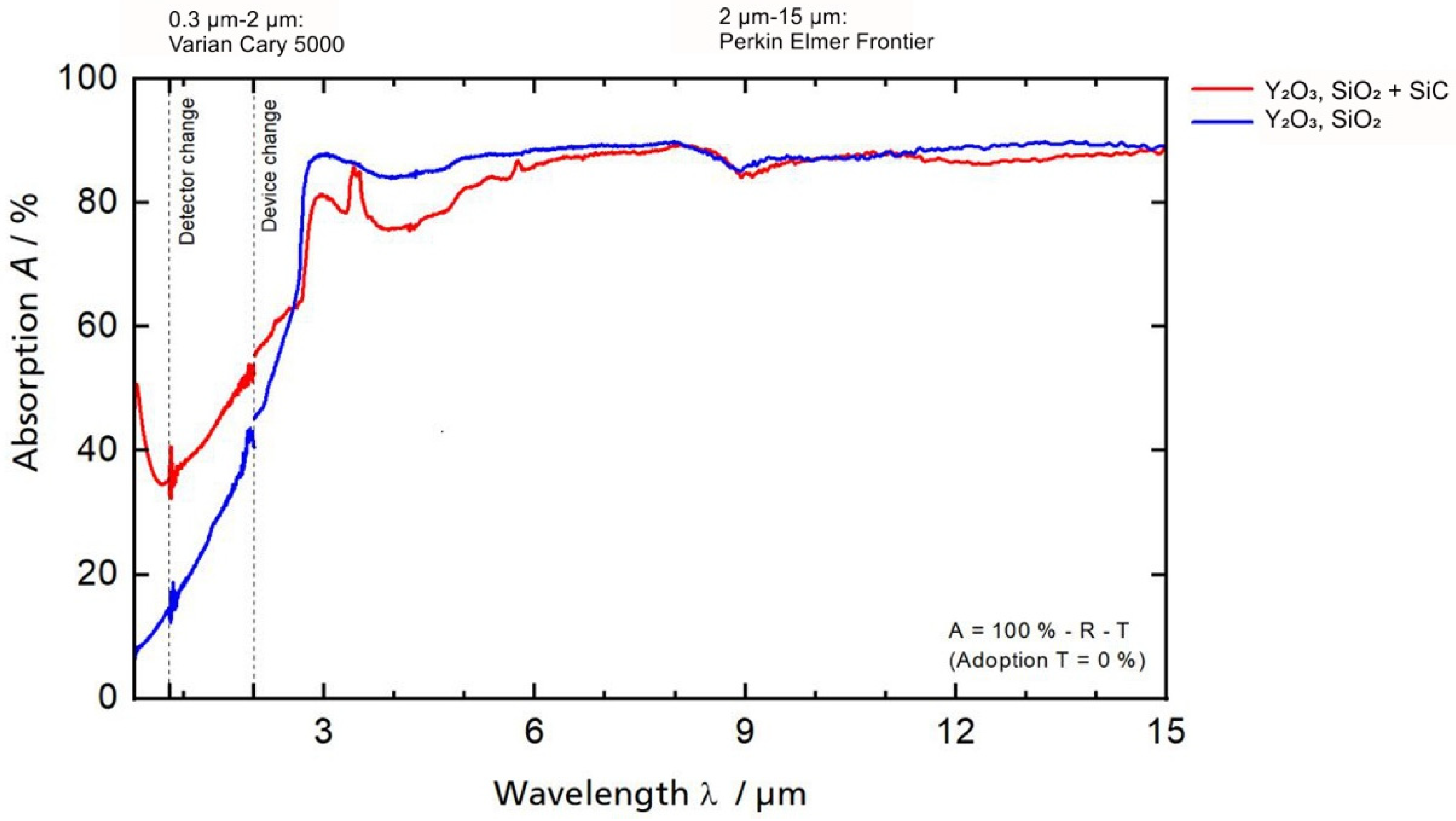
To confirm the assumption, the absorption values of the mentioned oxidic base materials (Y2O3, Grade C, Höganäs AB, Höganäs, Sweden; SiO2, Zandosil 30, Heraeus, Hanau, Germany) were analyzed by integrating sphere measurements and compared with the literature values of SiC. The Varian Cary 5000 UV-VIS-NIR spectrometer (Agilent Technologies Inc., Santa Clara, CA, USA) was used to measure the absorbance values over a wavelength range of 0.3 to 15 µm. To analyze the absorption values, samples of powdery matrix material with different compositions were pressed. The method was as follows:
Attrition milling in isopropyl alcohol for 4 h
Uniaxial Pressing to 16 × 16 × 4 mm3;
Cold isostatic pressing at 250 MPa
Debinding at 600 °C for 1 h in air.
Table 2 gives an overview of the sample compositions tested.
Based on the analyzed oxidic materials, a matrix system will be selected. The corresponding phase diagram for the matrix material system consisting of SiO
2 and Y
2O
3 can be found in source [
18]. Following the material and laser selection, initial parameter tests are carried out for melting the pressed samples under variation of the laser power (P
L) between 10 and 100 W, laser feed rate (v) between 200 and 16,000 mm/min and laser spot diameter (d) of 1 mm. The energy density (E) was considered as a comparative value. The samples were evaluated by means of ceramographic cross-sections, electron microscope and X-ray diffraction. The best parameter sets form the starting point for the first tests with the new additive manufacturing process described in
Figure 1.
3. Results
Using the pressed samples prepared as described in
Section 2, the integrating sphere measurement was carried out to determine the absorption values of different compositions of SiO
2 and Y
2O
3. The results are shown in
Figure 2.
From the results of the integrating sphere measurements, it can be seen that the selected oxide ceramic matrix materials SiO
2 and Y
2O
3 show significantly higher absorption values (about 90%) at a comparatively high laser wavelength of 10.6 μm than the SiC fiber material with 66% [
17]. Due to the proven difference in absorption values, the following tests are carried out with a mixture of SiO
2 and Y
2O
3 in a stoichiometric ratio of 2:1. The composition is derived from the eutectic produced in this ratio and the associated low melting temperature (about 1775 °C [
18].
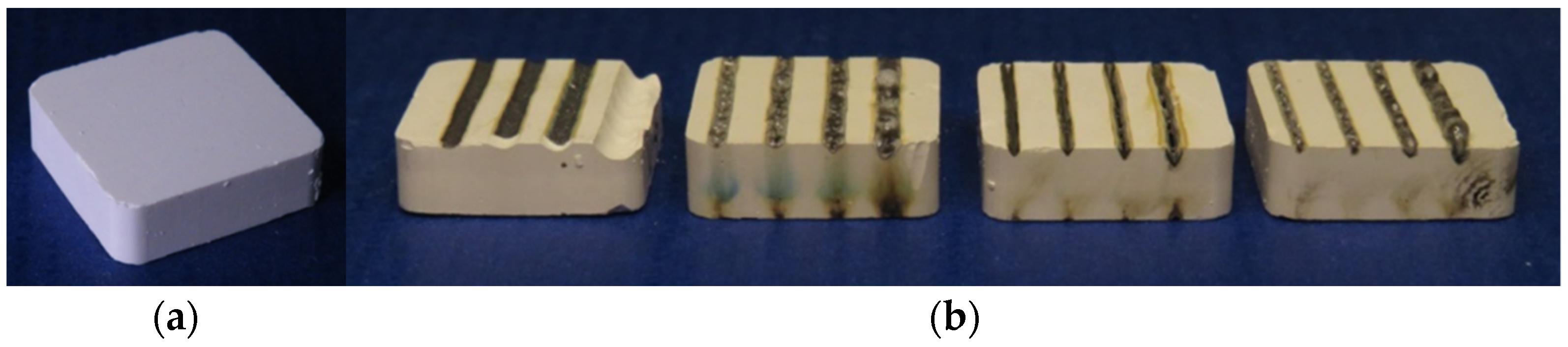
To investigate the effect of the molten bath on the fiber material, particulate silicon carbide (SiC; F1200, ESK-SIC GmbH, Frechen, Germany) with a volume fraction of 10% was added as a substitute to the matrix system. The powder mixtures were then mixed with organic binders, ground and processed into granules. This was formed into cuboids measuring 16 mm × 16 mm × 4 mm by cold isostatic pressing (see
Figure 3). The organic material was then debound at temperatures above 500 °C.
The pressed samples were partially melted in the first experiments using a laser (Diamond J-3 10.6 400 W OEM Laser, Coherent, Palo Alto, CA, USA) of 10.6 µm wavelength. The investigation of the single-track tests showed a different reaction of the material to the laser parameter variation of laser power, feed rate and spot diameter.
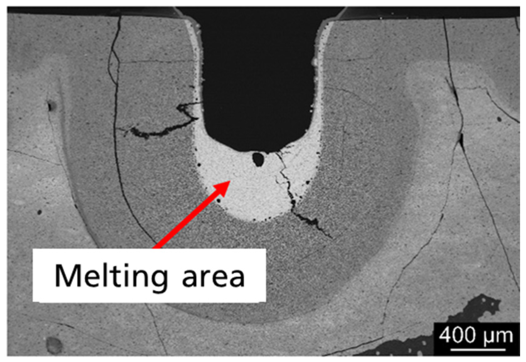
Figure 4 shows a cross-section of the track tests with λ = 10.6 µm for the material composite. The sample shows a homogeneous melt pool with a dense structure that has not solidified in thermodynamic equilibrium due to the extremely high cooling rate.
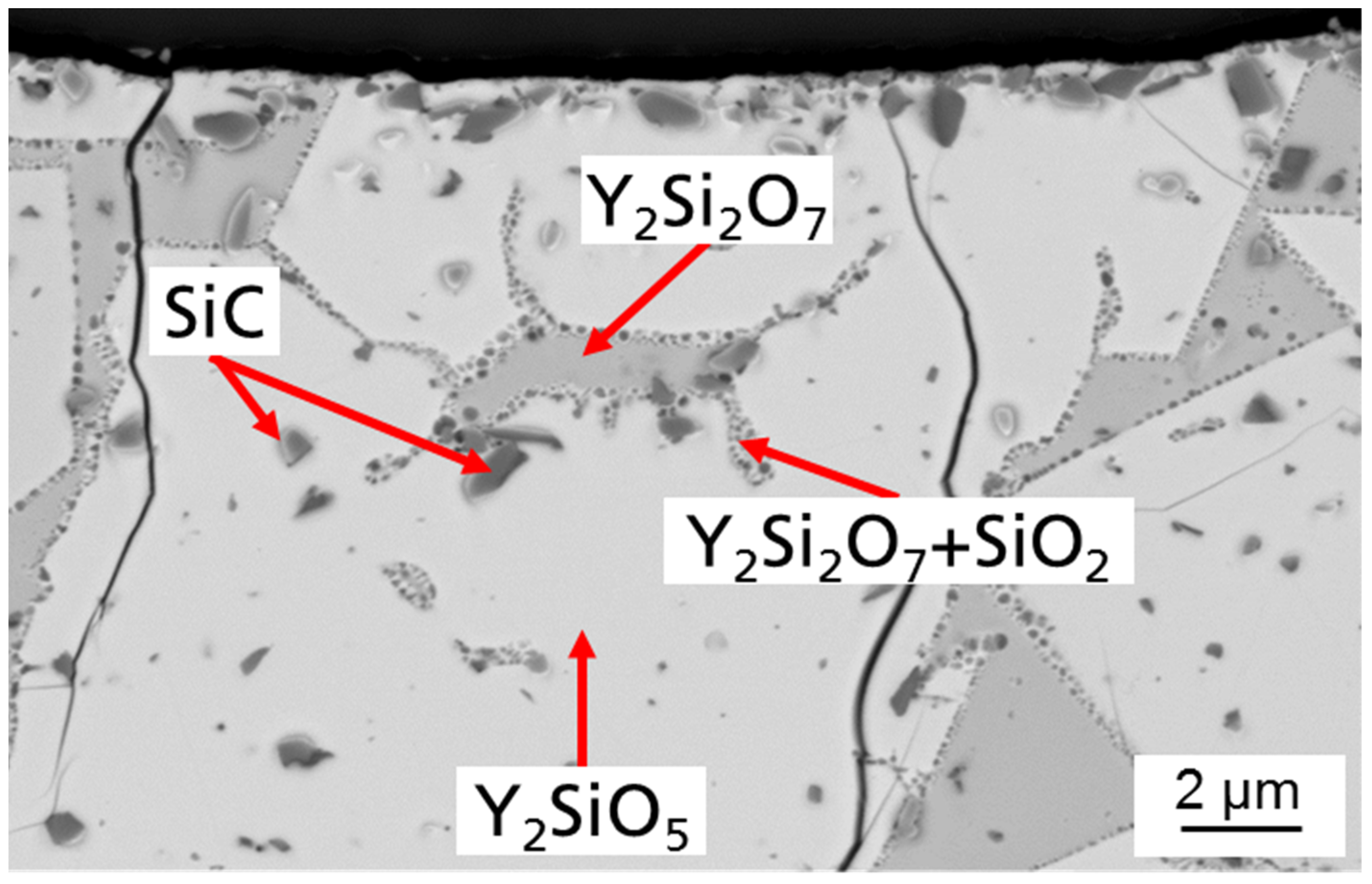
A cross-section with higher enlargement of a press specimen with 10 vol.% SiC is shown in
Figure 5. According to the phase diagram [
18], it was to be expected that mainly yttrium disilicate with embedded SiC would form.
Measuring the composition by EDS (Energy dispersive spectroscopy) (
Figure 6), four different phases could be identified by the stoichiometric ratio of the elements: yttrium disilicate, yttrium monosilicate, silica and silicon carbide. This non-equilibrium state is not in accordance with the phase diagram but is caused by the rapid cooling of the melt. However, the evaporation of Si-O species during processing leads to a partial reduction in the yttrium disilicate with the formation of more yttrium monosilicate compared to the residual amount of silica. A phase of yttrium disilicate with silicon oxide is deposited on the edge of the yttrium disilicate crystals by segregation of the yttrium monosilicate.
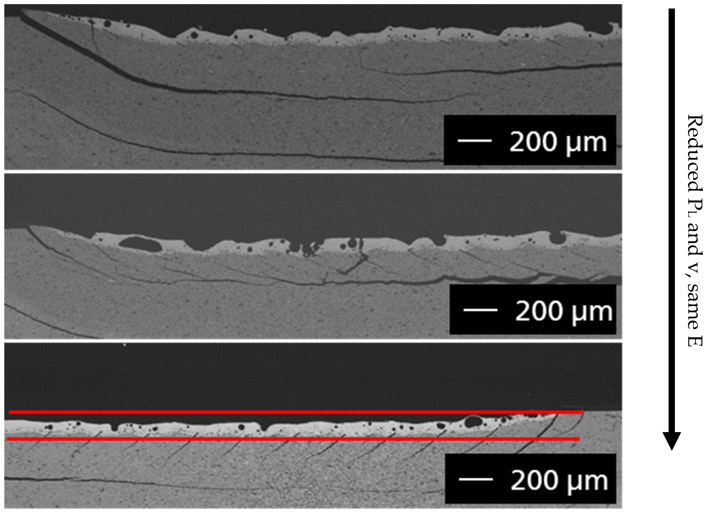
The cross-sections of the surface melt tests (
Figure 7) show similar laser penetration depths of around 140 µm from top to bottom, with reduced laser power, lower feed rate and the same energy density. Viewed from the surface, the samples show no macroscopic defects (delamination, cracking, color change), even when repeatedly processing the same surface with the same parameters. This is essential for the planned welding process, as the layer-by-layer structure requires repeated laser exposure of a surface.
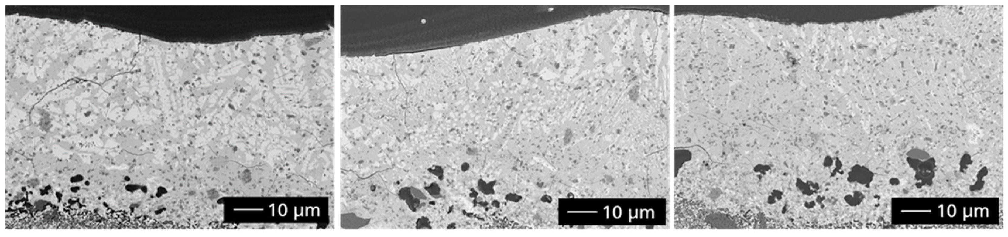
The characterization of the microstructure formation of the melting regions in
Figure 7 was carried out by means of cross-sections and their analyses in the field emission scanning electron microscope (FESEM: NVision40 or Ultra55, Carl Zeiss AG, Oberkochen, Germany) (
Figure 8) and X-ray diffraction (XRD: D8, Bruker AXS, Karlsruhe, Germany).
Depending on the power parameters of the laser, the chemical composition of the sample changes. Higher energy inputs lead to vaporization of Si-O and thus to a reduction of the yttrium disilicate with the formation of yttrium monosilicate. It is a benefit for the process to reduce the laser power and the feed rate at the same energy density. As the tests (
Figure 8) show, this resulted in a higher amount of the disilicate phase in the cross-sections.
Based on the results of the melting experiments on pressed powder tablets, the next step was to test the CMC production by laser technology on fiber composites consisting of Y
2O
3-SiO
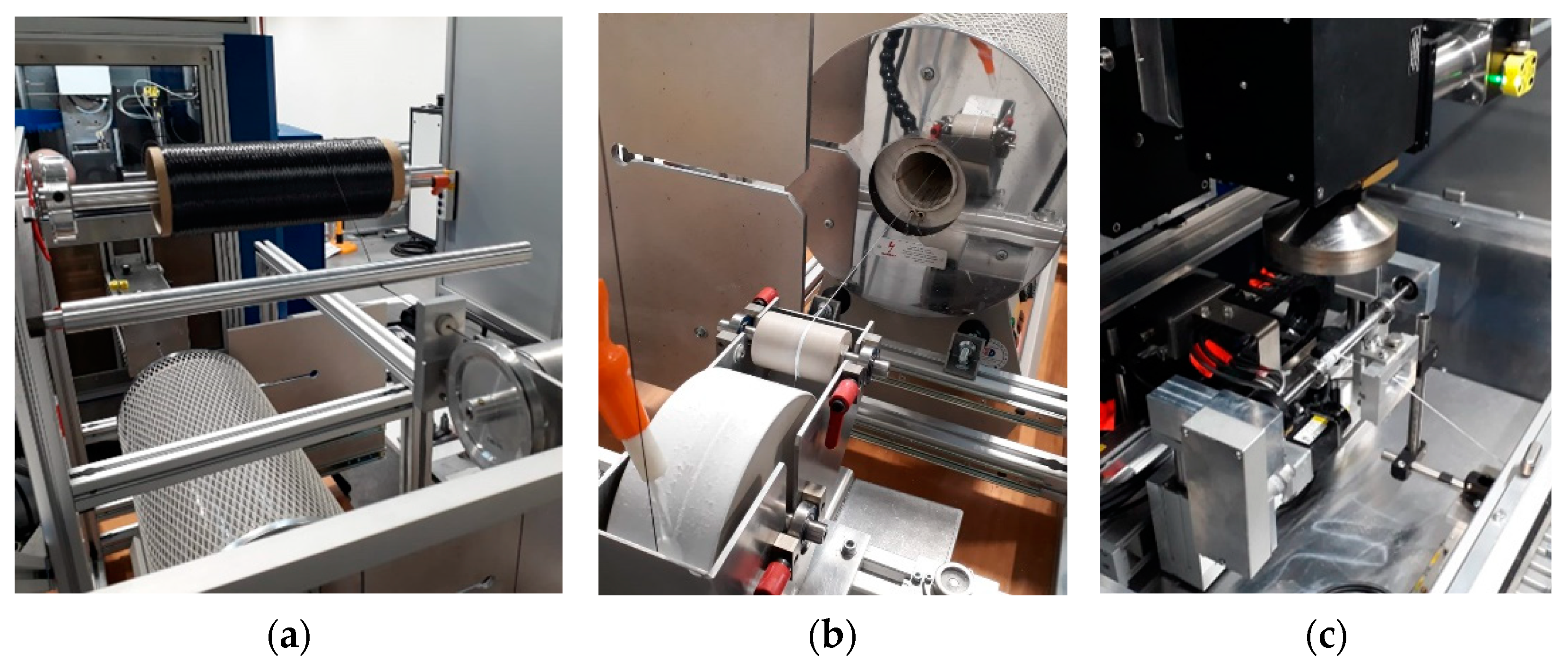
2 (1–2 mol) and the fiber material (Tyranno SA3, Ube Ind., Tokyo, Japan), as can be seen in the detailed images in
Figure 9, the first samples were set up with the newly developed system.
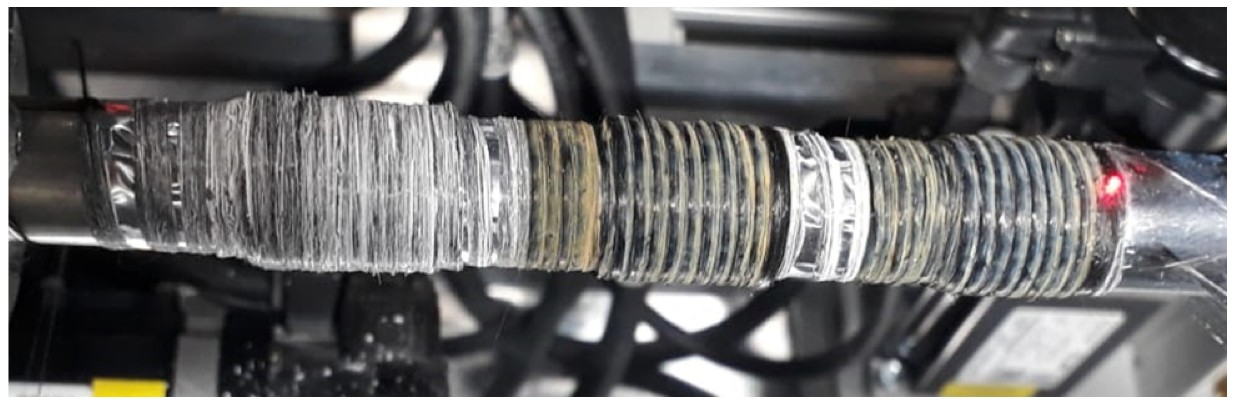
Following the functional tests of the system, the first samples were processed by laser, as can be seen in
Figure 10.
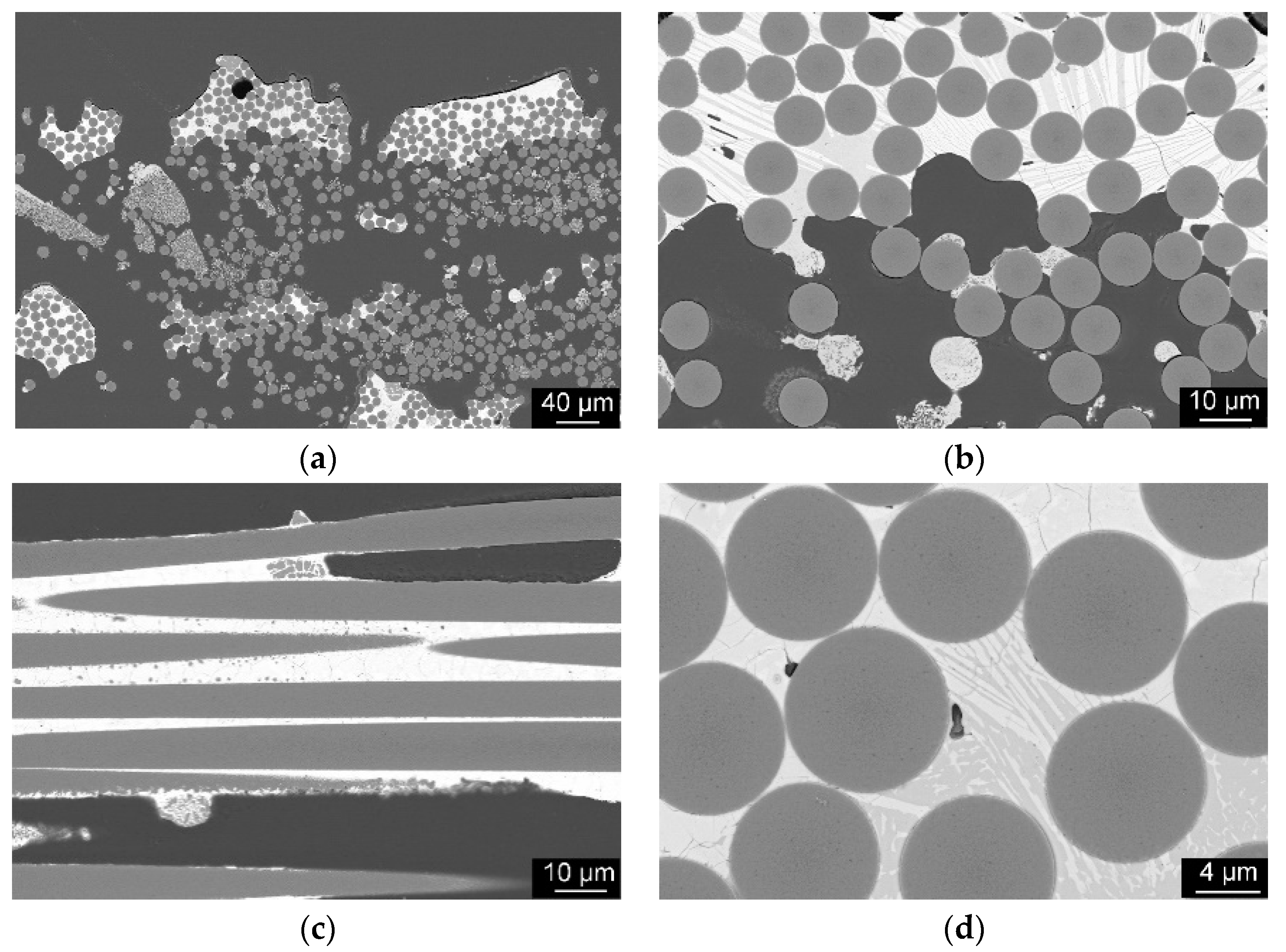
As can be seen in the cross-sections in
Figure 11, it was confirmed that the fibers were not damaged by the laser, as expected. Damage only occurred in isolated cases where minimal matrix material was present. The transition areas between fiber and matrix correspond to the expectations of a CMC. In the images, the fibers appear to be embedded in the matrix. This is indicated by the grain structures of the matrix, which do not continue in the fiber, and a step in the cross-sections between fiber and matrix.
4. Conclusions
In summary, it can be said that in the experiments with the press specimens, the use of the wavelength of 10.6 µm made it possible to melt the matrix systems. The tests with SiC-fiber material showed that a homogeneous infiltration of the fiber bundles with matrix material during the winding process is possible. However, the amount of matrix material between the fibers of the fiber bundle still has to be increased. After the welding process, there is still insufficient matrix between the fibers. Due to the high wavelength of the CO2 lasers (λ = 10.6 µm), the laser power is predominantly absorbed close to the surface (100–200 µm). Thus, the melting process takes place close to the surface. In order to increase the penetration depth, the laser parameters are varied in further experiments (feed rate, laser power, laser relative movement). The fiber material (Tyranno SA3, Ube Industries, Tokyo, Japan) used was not damaged by the laser during processing. If the laser power was too high (over 100 W), mixing with the matrix material occurred on the fiber surface.
As an outlook for the processing technique of CMC using laser technology described in the paper, the following can be noted. The proportion of infiltrated matrix powder must be increased, by changing the binder system, or by increasing the penetration depth of the laser in the melting area under controlled energy density by varying the laser power, feed rate and scanning strategy. To prevent damage to the fibers, the laser power should be kept under 50 W and the feed rate over 4000 mm/min. The scanning strategy should be adapted so that the process zone is scanned several times. For example, oscillating, circular or rectangular scanning patterns of the laser beam could be used.


 ,
, 


