Thermal Deformation of PA66/Carbon Powder Composite Made with Fused Deposition Modeling

Abstract
1. Introduction
2. Materials and Methods
2.1. Materials
2.2. Methods
2.2.1. Material Model
2.2.2. FDM Numerical Processing
2.2.3. FDM Experiments
3. Results and Discussion
3.1. Material
3.2. Optimal Processing Parameters
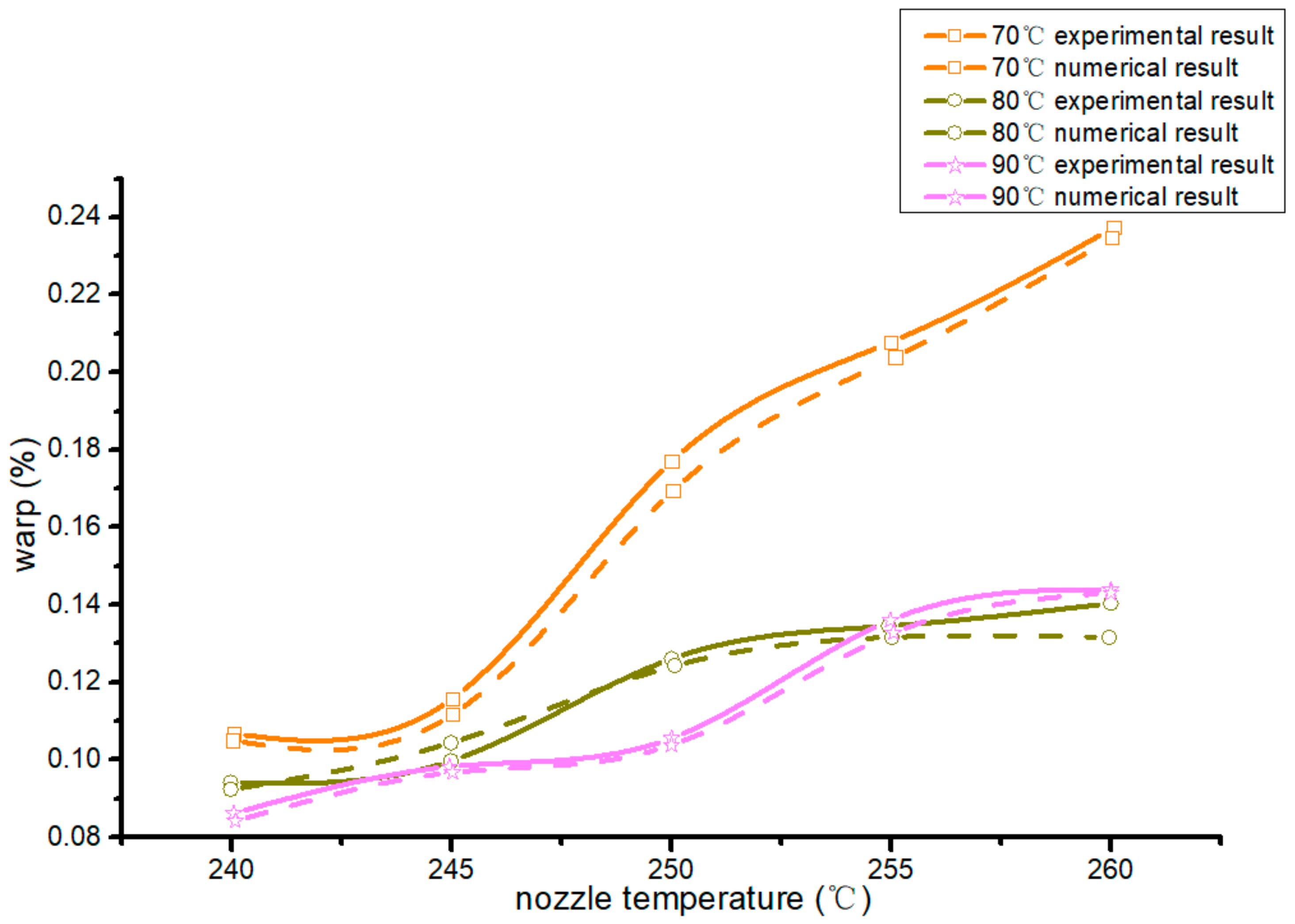
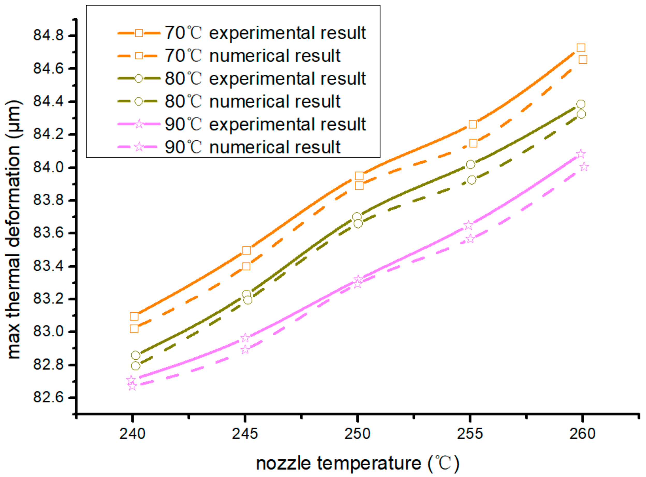
3.2.1. Nozzle and Hot-Bed Temperature
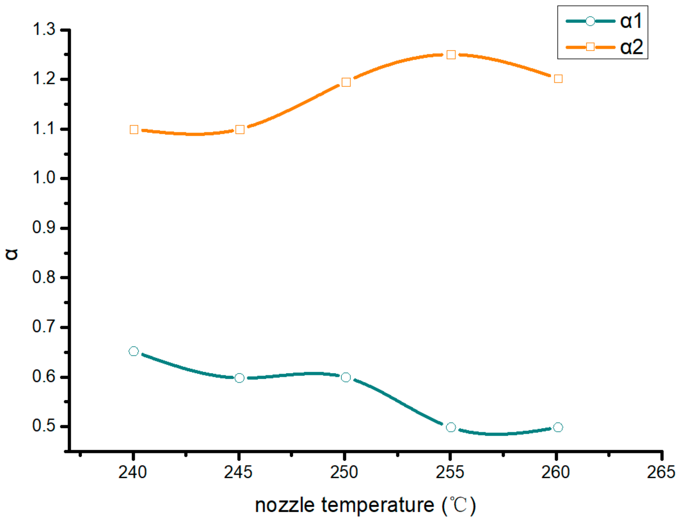
3.2.2. Speed Ratio of Extrusion to Filling
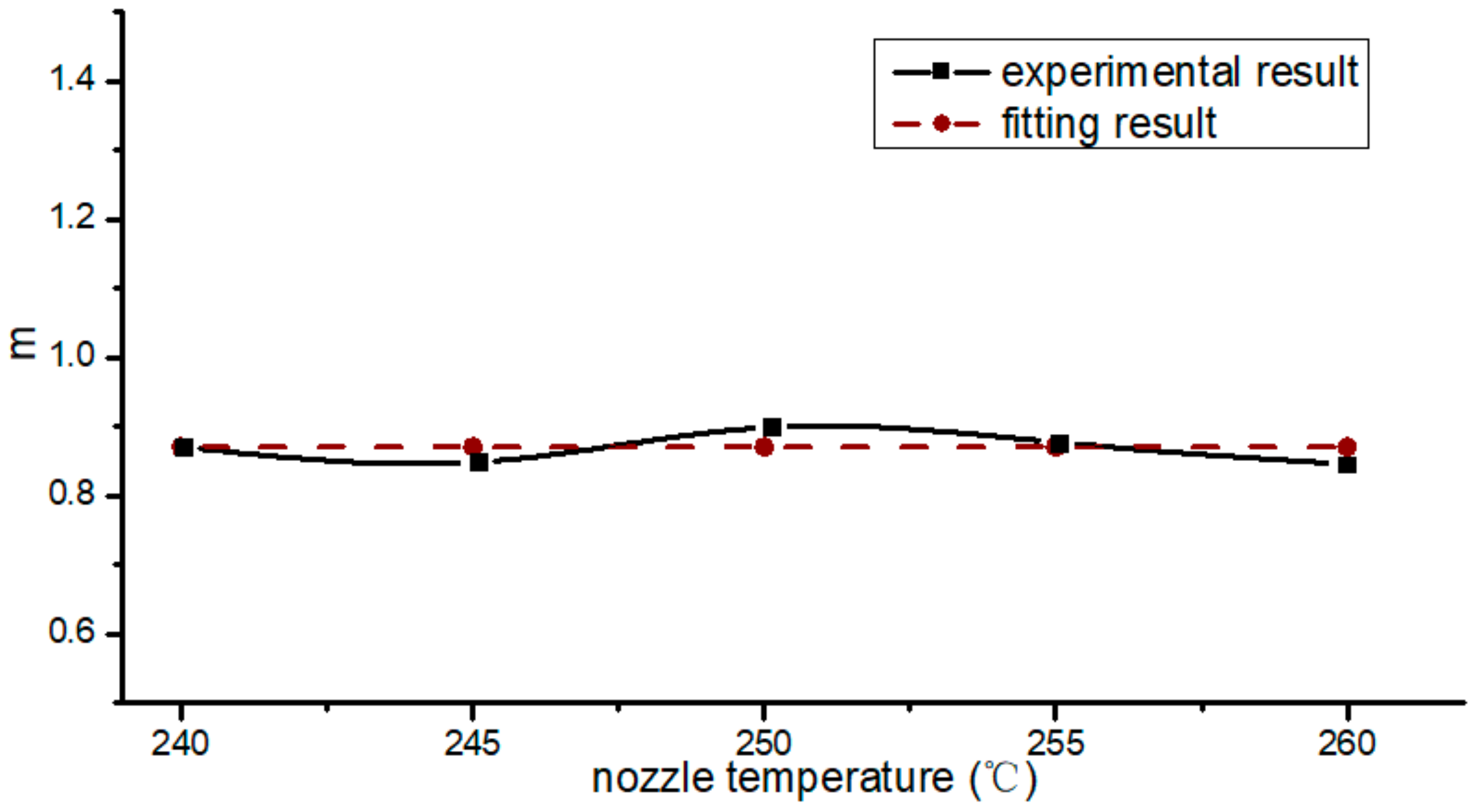
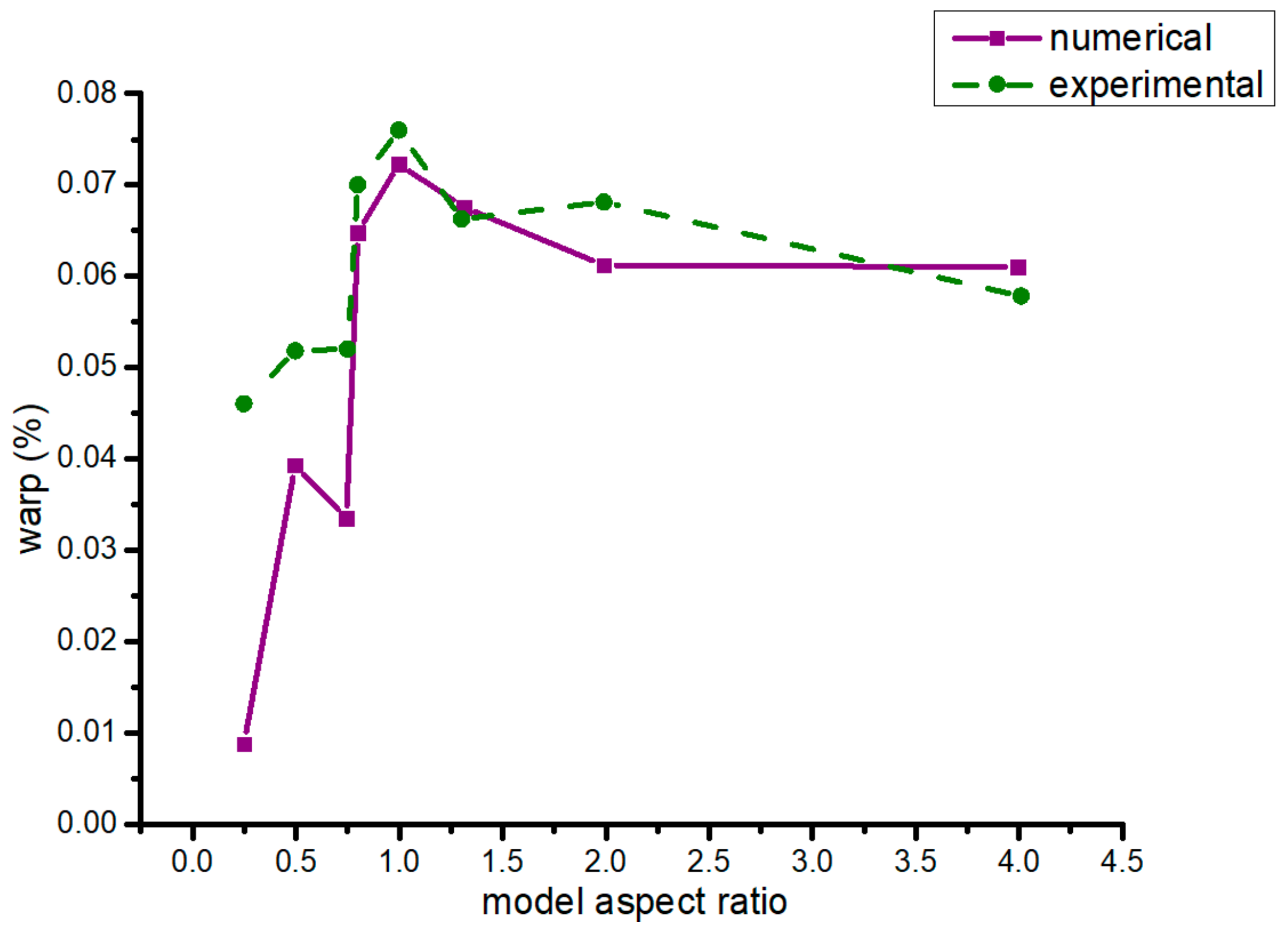
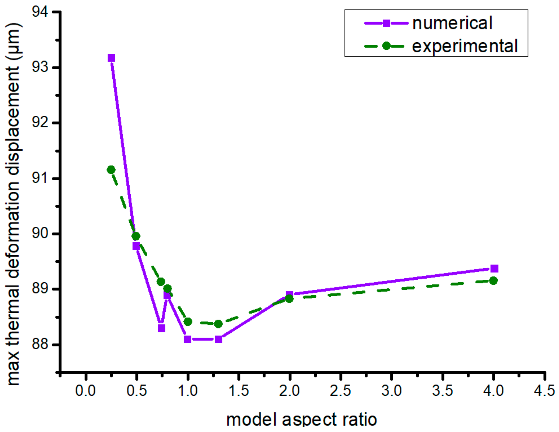
3.2.3. Model Aspect Ratio
4. Conclusions
Author Contributions
Funding
Conflicts of Interest
References
- Yao, S.; Jin, F.; Rhee, K.; Hui, D.; Park, S. Recent advances in carbon-fiber-reinforced thermoplastic composites: A review. Compos. Part B Eng. 2018, 142, 241–250. [Google Scholar] [CrossRef]
- Garima, M.; Kyong, Y.R.; Vesna, M.S.; David, H. Reinforcements in multi-scale polymer composites: Processing, properties, and applications. Compos. Part B Eng. 2018, 138, 122–139. [Google Scholar]
- Blok, L.G.; Longana, M.L.; Yu, H.; Woods, B.K.S. An investigation into 3D printing of fibre reinforced thermoplastic composites. Addit. Manuf. 2018, 22, 176–186. [Google Scholar] [CrossRef]
- Sun, Q.; Rizvi, G.M.; Bellehumeur, C.T.; Gu, P. Effect of processing conditions on the bonding quality of FDM polymer filaments. Rapid Prototyp. J. 2008, 14, 72–80. [Google Scholar] [CrossRef]
- Lu, G.; Liu, X.; Zhang, P.; Bao, L.; Zhao, B. Nanoarchitectonic Composites of Mixed and Covalently Linked Multiwalled Carbon Nanotubes and Tetra-[alpha-(p-amino) benzyloxyl] Phthalocyanine Zinc(II). J. Nanosci. Nanotechnol. 2020, 20, 2713–2721. [Google Scholar] [CrossRef] [PubMed]
- Wang, H.; Zhang, H.; Tang, D.; Goto, K.; Watanabe, I.; Kitazawa, H.; Kawai, M.; Mamiya, H.; Fujita, D. Stress dependence of indentation modulus for carbon fiber in polymer composite. Sci. Technol. Adv. Mater. 2019, 2, 412–420. [Google Scholar] [CrossRef] [PubMed]
- Yang, M.; Jiao, W.; Yang, F.; Ding, G.; Zou, H.; Xu, Z.; Wang, R. Simulation and measurement of cryogenic-interfacial-properties of T700/modified epoxy for composite cryotanks. Mater. Des. 2019, 182. [Google Scholar] [CrossRef]
- Kamarian, S.; Bodaghi, M.; Isfahani, R.; Shakeri, M.; Yas, M. Influence of carbon nanotubes on thermal expansion coefficient and thermal buckling of polymer composite plates: Experimental and numerical investigations. Mech. Based Des. Struct. Mach. 2019. [Google Scholar] [CrossRef]
- Gao, X.; Qin, Z.; Guo, Y.; Wang, M.; Zan, T. Adaptive Method to Reduce Thermal Deformation of Ball Screws Based on Carbon Fiber Reinforced Plastics. Materials 2019, 12, 3113. [Google Scholar] [CrossRef] [PubMed]
- Karthicksundar, R.; Rajendran, B.; Kumar, P.; Devaganesh, S. Thermal characterization of carbon nanoparticle infused GFRP using dynamic mechanical analyzer. Mater. Res. Express 2019, 6. [Google Scholar] [CrossRef]
- Vinyas, M.; Athul, S.; Harursampath, D.; Thoi, T. Experimental evaluation of the mechanical and thermal properties of 3D printed PLA and its composites. Mater. Res. Express 2019, 6. [Google Scholar] [CrossRef]
- Tan, C.; Zhang, W.; Wang, Q.; Li, S.; Liu, G.; Yao, H.; Yang, Y. Viscoelastic behavior of carboxylated multi-walled carbon nanotube reinforced epoxy composites with various frequencies. Mater. Res. Express 2019, 6. [Google Scholar] [CrossRef]
- Ebrahimi, F.; Qaderi, S. Stability analysis of embedded graphene platelets reinforced composite plates in thermal environment. Eur. Phys. J. Plus 2019, 134. [Google Scholar] [CrossRef]
- Dorigato, A.; Fredi, G.; Pegoretti, A. Application of the thermal energy storage concept to novel epoxy-short carbon fiber composites. J. Appl. Polym. Sci. 2019, 136, 47434. [Google Scholar] [CrossRef]
- Zhu, P.; Lei, Z.; Liew, K. Static and free vibration analyses of carbon nanotube-reinforced composite plates using finite element method with first order shear deformation plate theory. Compos. Struct. 2012, 94, 1450–1460. [Google Scholar] [CrossRef]


| Material | Unit | PA66 | Carbon Powder |
|---|---|---|---|
| Density | 1150 | 1750 | |
| Thermal conductivity | 0.35 | 10 | |
| Thermal expansion coefficient (10−5) | 7.2 | –3.8 | |
| Elastic modulus (106) | Pa | 1200 | 228,000 |
| Poisson’s ratio | 0.4 | 0.307 |
| Temperature (°C) | PA66’s Specific Heat Capacity | Carbon’s Specific Heat Capacity |
|---|---|---|
| 15 | 681 | 7531 |
| 50 | 1849 | 7531 |
| 75 | 2029 | 7531 |
| 100 | 2171 | 7531 |
| 125 | 2468 | 7531 |
| 150 | 2795 | 7531 |
| 175 | 3186 | 7531 |
| 191 | 4499 | 7531 |
| 200 | 2595 | 7531 |
| 220 | 2429 | 7531 |
| 240 | 2412 | 7531 |
| 260 | 2428 | 7531 |
| wt % | CTE (×10−5) | E (109) | ν | ρ | λ |
|---|---|---|---|---|---|
| 1/°C | Pa | W/m·°C | |||
| 20 | 5.8892 | 1.7632 | 0.3879 | 1234.7 | 0.508 |
| 15 | 6.2244 | 1.6275 | 0.391 | 1212.3 | 0.46 |
| 10 | 6.5545 | 1.5065 | 0.394 | 1190.8 | 0.42 |
| 5 | 6.8797 | 1.39702 | 0.397 | 1170.1 | 0.38 |
| Temperature (°C) | 15 | 50 | 75 | 100 | 125 | 150 | 175 | 191 | 200 | 220 | 240 | 260 | |
|---|---|---|---|---|---|---|---|---|---|---|---|---|---|
| wt % | |||||||||||||
| 5 | 1518 | 3708 | 4014 | 4189 | 4648 | 5259 | 6570 | 7815 | 6068 | 4670 | 4582 | 4626 | |
| 10 | 1835 | 3868 | 4220 | 4448 | 4862 | 5358 | 6724 | 7842 | 6207 | 4820 | 4758 | 4794 | |
| 15 | 2151 | 4052 | 4345 | 4580 | 4971 | 5440 | 6632 | 7864 | 6261 | 4971 | 4932 | 4946 | |
| 20 | 2467 | 4275 | 4533 | 4790 | 5195 | 5618 | 6888 | 7886 | 6372 | 5140 | 5125 | 5085 | |
| wt % | Warp 1 (%) | Warp 2 (%) | Warp 3 (%) | Mean (%) |
|---|---|---|---|---|
| 0 | 0.2013 | 0.1934 | 0.1911 | 0.1953 |
| 20 | 0.1028 | 0.0925 | 0.0994 | 0.0982 |
| wt % | Maxd1 (μm) | Maxd2 (μm) | Maxd3 (μm) | Mean (μm) |
|---|---|---|---|---|
| 0 | 90.77 | 90.98 | 89.63 | 90.46 |
| 20 | 80.54 | 80.30 | 79.66 | 80.17 |
© 2020 by the authors. Licensee MDPI, Basel, Switzerland. This article is an open access article distributed under the terms and conditions of the Creative Commons Attribution (CC BY) license (http://creativecommons.org/licenses/by/4.0/).
Share and Cite
Li, F.; Sun, J.; Xie, H.; Yang, K.; Zhao, X. Thermal Deformation of PA66/Carbon Powder Composite Made with Fused Deposition Modeling. Materials 2020, 13, 519. https://doi.org/10.3390/ma13030519
Li F, Sun J, Xie H, Yang K, Zhao X. Thermal Deformation of PA66/Carbon Powder Composite Made with Fused Deposition Modeling. Materials. 2020; 13(3):519. https://doi.org/10.3390/ma13030519
Chicago/Turabian StyleLi, Fei, Jingyu Sun, Hualong Xie, Kun Yang, and Xiaofei Zhao. 2020. "Thermal Deformation of PA66/Carbon Powder Composite Made with Fused Deposition Modeling" Materials 13, no. 3: 519. https://doi.org/10.3390/ma13030519
APA StyleLi, F., Sun, J., Xie, H., Yang, K., & Zhao, X. (2020). Thermal Deformation of PA66/Carbon Powder Composite Made with Fused Deposition Modeling. Materials, 13(3), 519. https://doi.org/10.3390/ma13030519