Abstract
Rotavator blades are prone to significant wear because of the abrasive nature of sand particles. The aim of this research work is to investigate the effect of cryogenic treatment and post tempering on abrasive wear behavior, in the presence of angular quartz sand (grain size of 212–425 μm), of rotavator blade material of boron steel (30MnCrB4). Cryogenic treatment has caused an improvement in the abrasive wear resistance and microhardness of 30MnCrB4 by 60% and 260.73%, respectively, compared to untreated material due to enhancement in hardness, the conversion of retained austenite into martensite, and the precipitation of secondary carbides in boron steel after exposure to cryogenic temperature. Economic analysis justifies the additional cost of cryogenic treatment.
1. Introduction
Rotavator and other earth engaging implements are needed in the farming industry, where they are used for seed bed preparation via the mixing of all crop residues to improve soil’s organic health and yield [1]. Agricultural implements wear out frequently due to abrasive action by sand/soil particles. Rotavator also gets worn out frequently due to abrasive action of sand/soil, leading to repeated replacement of its blades, which is quite uneconomical. Poor abrasive wear behavior makes farmers less efficient and plays a major role in raising the cost of agriculture [2] by adversely affecting farmers’ productivity, thereby making the whole process of agriculture economically unviable. Scientists and researchers have applied different techniques such as coatings [3,4,5,6,7,8,9,10,11,12,13,14], carburizing [15], nitriding and carbonitriding [15], boriding [15,16,17,18,19,20], and shot peening [21] to enhance the working life of rotavator blades. These techniques have shown promising results with regard to improving wear resistance in the short term, but limited data related to the long term success of these techniques is reported in the published work. These techniques largely improve a very thin layer of surface material, and chipping off this layer leads to severe wear. Therefore, there is need to explore material processing techniques for improving the abrasive wear resistance of rotavator blade material [22,23,24,25].
Conventional heat treatment (CHT) is simple, flexible, and economical, and is largely used for manipulating the microstructure, leading to alterations in the mechanical properties of the material used for earth engaging implements [26,27]. Suitable selection of the heat treatment temperature and subsequent cooling rate helps in attaining the desirable properties as per the requirements of application. Processing of materials at a low temperature in the range of −80 °C to −196 °C is another material processing technique used for achieving desirable properties in materials. Different review articles [28,29,30,31,32,33] pertaining to cryogenic processing have reported CHT’s potential in improving the properties of materials, especially ferrous-based cutting tools/implements. The efficacy of cryogenic treatment in improving the properties of nonferrous materials has also been established by different research studies [34,35,36,37,38,39]. T Singla et al. [28] have extensively examined various cryogenic cycles and their parameters for different ferrous materials. The authors have recommended using tempering post cryogenic treatment for further improving the properties of materials. The optimum number of cycles of post tempering, temperature, and time may vary for different materials. These can be optimized only based on experimental observations for different materials. Cryogenic treatment also plays a significant role in eco-friendly machining of materials, especially difficult-to-cut materials, by replacing conventional cutting fluids with liquified nitrogen [40,41,42]. The cooling medium provided to the cutting zone during cryogenic cooling evaporates immediately and comes back to the atmosphere without any pollution [40].
In this work, comparative study has been conducted amongst different thermal treatments, with a major focus on cryogenic treatment, on rotavator blade material 30MnCrB4 vis-à-vis hardness, impact strength, and abrasive wear resistance. The alterations in mechanical behavior have been correlated with microstructural evolution. Economic analysis justifying the additional cost of cryogenic treatment due to its improvement in the performance of rotavator blade material has been reported.
2. Materials and Methods
2.1. Untreated Material
In the present work, low-carbon boron steel (DIN 30MnCrB4) is selected as an untreated material, which is widely used for manufacturing of rotavator blades [43,44]. Boron steel exhibits better hardness, sliding, and abrasive wear resistance due to the presence of hardenability enhancers like chromium and boron, as compared to high-carbon steel [25]. The chemical composition of as-received material is tested using optical emission spectrometer (GNR Solaris CCD-Plus, Torino, Italy). The obtained chemical composition along with standard composition are presented in Table 1.

Table 1.
Chemical composition of boron steel (30MnCrB4) in weight (%).
2.2. Methods
The schematic plan depicting the various thermal treatments and mechanical and metallurgical investigations is given in Figure 1.
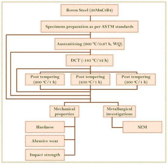
Figure 1.
Schematic plan of thermal treatments and different investigations.
2.2.1. Austenitization
A pilot study [45,46] was undertaken to decide about the parameters of austenitization, such as austenitic temperature, soaking period, and quenching medium. L9 Taguchi DOE (design of experiments) was adopted for this purpose. The design factors along with three levels for each factor are shown in Table 2.
Table 2.
Factor and level for DOE (design of experiments) of austenitization.
The output parameters were abrasive wear volume loss, hardness, and impact toughness. It was observed that optimum results were attained corresponding to the austenitization temperature of 900 °C with a soaking period of 40 min and water as a quenching media. The complete details of the pilot study are given in research study by Singh et al. [46]. Accordingly, in this work, these optimized austenitization parameters have been chosen for further investigation of low-temperature treatment. Muffle furnace (Jupiter engineering works, New Delhi, India) has been used for austenitization, and all specimens have been properly cleaned ultrasonically using acetone before heat treatment to remove the oil, dust, foreign particles, and grease from the surface of specimens. The muffle furnace was allowed to reach 900 °C, and specimens were placed inside the muffle furnace. The specimens were held at that temperature for 40 min and then water-quenched.
2.2.2. Deep Cryogenic Treatment
Austenitization was immediately, without any time lag, followed by deep cryogenic treatment (DCT), and its parameters are reported in Table 3. All the specimens were again ultrasonically cleaned with acetone before deep cryogenic processing. DCT was conducted using cryogenic processor (3241-1-SAMSON, Super Cryogenic Systems Pvt. Ltd., Noida, India). Cryogenic treatment set up was brought to the desired temperature using computer controls in a well-insulated chamber with liquid nitrogen as a working medium.
Table 3.
Description of deep cryogenic treatment (DCT) process parameters.
2.2.3. Post Tempering
Post tempering treatment was given to all the cryogenically treated specimens in three different groups at three tempering temperatures. The three sets of specimens were subjected to post tempering cycle at 200 °C, 250 °C, and 300 °C, respectively, for 1 h. The complete details of austenitization, DCT, and tempering cycles are presented in Figure 2. The various thermal cycles adopted for the present work and coding of specimens are detailed in Table 4.
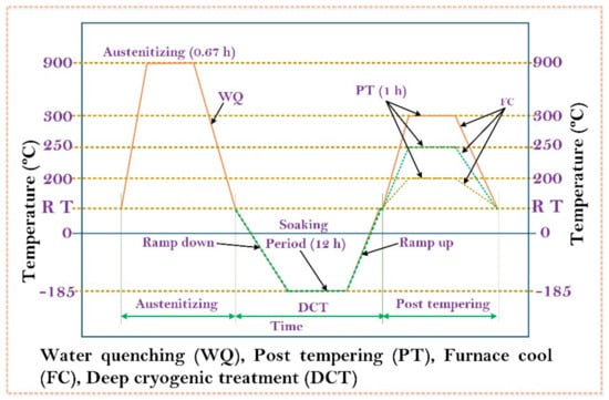
Figure 2.
Thermal treatment cycles.
Table 4.
Thermal treatment schedules and coding of specimens.
2.3. Metallurgical Investigation
Scanning electron microscopy, using JSM 6510LV (JEOL, Tokyo, Japan) was conducted for visualization of microstructure and study of fractography. For microstructure, the specimens were etched first with freshly prepared etchant 4% picric (picric acid 4 gm and ethanol 96 mL) by swabbing for 20–30 s followed by distilled water rinsing. They were then etched with 2% nital (nitric acid 2 mL and ethanol 98 mL) by swabbing for 15–25 s followed by distilled water rinsing. The specimens were dried in air and observed for obtaining SEM images.
2.4. Mechanical Properties
The micro hardness measurement was conducted as per ASTM E384 using digital micro Vickers hardness tester (RMHT-201, Radical, Ambala Cantt, India). Measurements were taken at five different locations of UT, CHT, CDCT-T0, CDCT-T1, CDCT-T2, and CDCT-T3 specimens. Four readings were taken at the periphery and one at the center of specimen. Vickers micro-hardness measurement was conducted using a 4.9 N load for a total cycle time of 40 s with a dwell time of 20 s. The average of five observations was computed and reported for this work.
Charpy V-notched impact test was performed as per ASTM E23-07a [47] using sub-size specimens (7.5 × 10 × 55) mm. Three specimens for each treatment CHT, CDCT-T0, CDCT-T1, CDCT-T2, and CDCT-T3 were tested, and observations with average value are reported in this work.
Specimens of size (76.2 × 25.4 × 6) mm, as shown in Figure 3a, were prepared using tabletop cutting equipment (Labotom 5, Struers, Ballerup, Denmark) for abrasive wear testing. Abrasive wear test was performed as per ASTM G65 [48] on the specimens of UT, CHT, CDCT-T0, CDCT-T1, CDCT-T2, and CDCT-T3 using abrasive wear test rig (TR-50-M7, Ducom, Bangalore, India) shown in Figure 3b. The parameters selected for abrasive wear testing are shown in Table 5. The values of speed, rotational speed of wheel, and sliding distance were selected to emulate the actual agricultural field conditions. Specimens were ultrasonically cleaned before the test to remove any foreign particles from the specimens. The weight of each specimen, before and after the experiment, was determined by using precision weighing balance (Citizen CY204, Denver Instruments GmbH, Denver, Germany) with a least count of 0.0001 g. The resulting weight loss was converted into abrasive wear loss in mm3. Each experiment was performed three times to minimize the experimental errors.
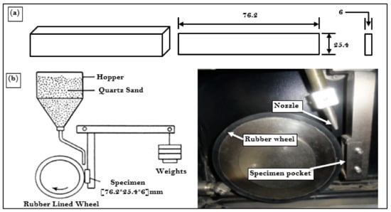
Figure 3.
Schematic view of (a) abrasive wear test specimen and (b) dry sand abrasion test rig.
Table 5.
Parameters used for three-body abrasion wear test (DSRW).
The abrasive wear study of the material was influenced by the size and morphology of abrasive sand. As per Avery [49], abrasive wear behavior of material was significantly affected by the sand particle size. The quartz sand was arranged for the test and standard sieve shaker (Kelsons Engineers and Fabricators, Kohlapur, India) was used to find out the particle size distribution. Particle size distribution for the used sand is presented in Figure 4. d10 and d90 of the quartz sand used for wear test were computed and marked on the particle distribution curve shown in Figure 4. It is clear from particle distribution curve that 80% of the quartz sand particles lie between 240 μm and 600 μm with an average particle size of 430 μm. The size of sand available in fields also lie in the same range as reported by Singh et al. [50].
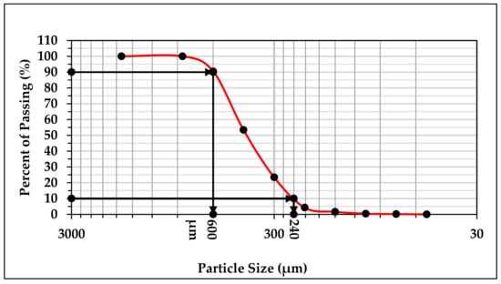
Figure 4.
Particle size distribution curve.
To obtain morphology of the quartz sand particle, scanning electron microscopy (JSM 6510LV, JEOL, Tokyo, Japan) was used for the present study, and same is shown in Figure 5. The hardness value of quartz sand is determined based on past studies [50,51] and found to be in the range of 1070–1200 HV. It is clearly shown in the SEM image of quartz sand that particles are highly angular, which is responsible for aggressive wear [52,53].
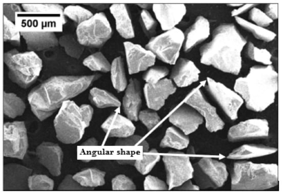
Figure 5.
The geometry of quartz sand.
3. Results and Discussions
3.1. Microstructure
The SEM micrograph of UT sample is characterized by presence of ferrite and pearlite structure, as shown in Figure 6a. The network of ferrite appeared as flat surface and pearlite as needle pattern surface [45]. During austenitization, ferrite and pearlite phases were transformed into austenite phase. Austenite is quite soft as compared to pearlite, and started transforming into martensite upon quenching in water. Formation of martensite has led to enhancement of hardness [54,55]. A sufficient fraction of retained austenite (RA) was also present upon quenching to room temperature, which is quite evident from microstructure of austenitized boron steel shown in Figure 6b. Few primary carbides and martensite formation have been identified and marked on SEM image shown in Figure 6b. During deep cryogenic treatment, retained austenite left after CHT was transformed into martensite. A significant fraction of martensite phase is lucidly visible in the SEM image shown in Figure 6c. Formation of secondary carbides on exposure to soaking temperature was also visible in microstructure of CDCT-T0 specimen. Soaking for long time helped in bringing more uniformity in distribution of secondary carbides, as shown in white spot encircled with red color, which led to improvement in hardness and wear resistance of the material [29,56,57,58]. The presence of martensite and secondary carbides in CDCT-T0 specimen were identified and marked in its SEM micrograph, as shown in Figure 6c. SEM micrograph of tempered post cryogenic treatment boron steel is shown in Figure 6d. It is evident from SEM image of CDCT-T1 specimen that post tempering resulted into grain coarsening and martensite decomposition. Transformation of martensite into tempered martensite and mechanical mixture of phases resulted in reduction of hardness and wear resistance of the CDCT-T1 specimen in comparison with that of CDCT-T0 sample. The results are in agreement with those reported by Kalsi et al. [32].
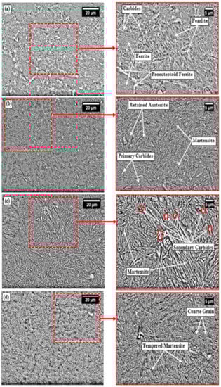
Figure 6.
SEM microstructures of (a) untreated, (b) conventional heat-treated (900 °C/0.67 h, water-quenched), (c) conventional heat-treated (900 °C/0.67 h, water-quenched) + deep cryogenic treatment (−185 °C/12 h), and (d) conventional heat-treated (900 °C/0.67 h, water-quenched) + deep cryogenic treatment (−185 °C/12 h) + tempering (200 °C/1 h, furnace-cooled).
3.2. Hardness
The Vickers micro-hardness of UT, CHT, CDCT-T0, CDCT-T1, CDCT-T2, and CDCT-T3 specimens was measured at five different locations for each sample, and the mean value was computed and shown in the form of bar chart in Figure 7. From the results drawn in Figure 7, it is clear that hardness increased in the specimens CHT (215.76%), CDCT-T0 (260.73%), CDCT-T1 (216.60%), CDCT-T2 (197.42%), and CDCT-T3 (179.19%), as compared to UT sample. The maximum improvement in the hardness was observed in CDCT-T0 sample due to conversion of RA into martensite and formation of secondary carbides after deep cryogenic treatment [57,59,60,61].
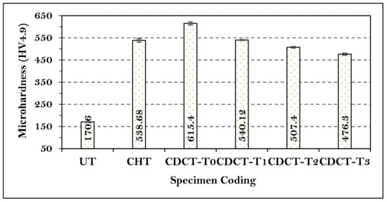
Figure 7.
Microhardness of untreated and treated material.
3.3. Impact Strength
A set of three specimens were prepared for analyzing the impact strength of material, and the mean of these three values was computed. The average value has been drawn in the form of bar chart as shown in Figure 8. From the results shown Figure 8, it is clear that impact strength increased in the specimens CDCT-T0 (50%), CDCT-T1 (75%), CDCT-T2 (82.5%), and CDCT-T3 (95%), compared to CHT sample. The maximum increase in the impact strength was observed in CDCT-T3 sample due to transformation of martensite, which formed during hardening, into tempered martensite along with secondary carbide formation and removal of residual stresses due to tempering post cryogenic treatment. The nucleation of carbides and precipitation of finer carbides increase the impact strength of material after deep cryogenic treatment. During cryogenic treatment, fine platelets of martensite are formed from the retained austenite, and these platelets promote the precipitation of fine carbides by a diffusion mechanism during tempering [58].
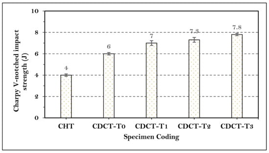
Figure 8.
Charpy V-notch impact strength results of treated material.
SEM fractography of impact specimens was conducted to examine the nature of fractured surface. Impact strength of CHT samples was the lowest, and cryogenic treatment caused improvement in impact strength by 50%, which was further enhanced by tempering. The SEM fractography images of the CHT, CDCT-T0, and CDCT-T3 specimens taken at the central region of the Charpy V-notch impact test specimens are shown in Figure 9. Flat regions surrounded by the fibrous regions, which were formed by tearing ridges in the CHT specimen shown in Figure 9a. The presence of rippled morphology with very few voids and few visible cracks accounted for its low impact energy absorption capacity. In the CDCT-T0 specimen shown in Figure 9b, cracking was observed with severe bubble/dimples coalescence along the grain boundaries. The presence of micro dimples on the fracture facets shows that a considerable amount of plastic deformation occurred prior to the fracture, resulting in absorption of increased impact energy of the cryo-treated specimen. In the CDCT-T3 specimen shown in Figure 9c, more cracking was observed is evident, along with dense micro dimples coalescence formation. The presence of many microcracks and crack branching with dense micro dimples indicates more plastic deformation occurred before fracture, resulting in increase in the impact strength of post-tempered cryogenic-treated specimens [58,62].
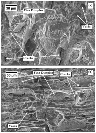
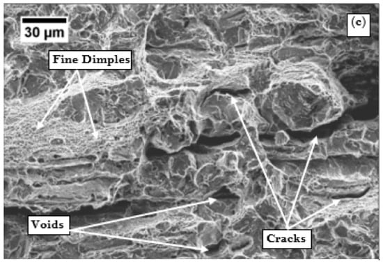
Figure 9.
SEM fractography images of impact samples of boron steel: (a) conventional heat-treated (900 °C/0.67 h, water-quenched), (b) conventional heat-treated (900 °C/0.67 h, water-quenched) + deep cryogenic treatment (−185 °C/12 h), and (c) conventional heat-treated (900 °C/0.67 h, water-quenched) + deep cryogenic treatment (−185 °C/12 h) + tempering (300 °C/1 h, furnace-cooled).
3.4. Abrasive Wear
Abrasive wear volume loss was computed from the weight loss and density of material (7.85 g/cm3) for each sample. The average abrasive wear volume loss was plotted in the form of bar chart as shown in Figure 10. It is clear from the results shown in Figure 10 that abrasive wear resistance increased in the specimens CHT (46.20%), CDCT-T0 (60.00%), CDCT-T1 (56.39%), CDCT-T2 (52.55%), and CDCT-T3 (48.87%), compared to UT sample. The maximum improvement in abrasive wear resistance was observed in CDCT-T0 sample due to conversion of RA into martensite and formation of secondary carbides after deep cryogenic treatment [57,61]. Post tempering increased wear volume loss with increase in tempering temperature attributable to decrease in hardness [63].
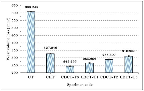
Figure 10.
Comparison of abrasive wear loss of untreated and treated material.
Worn Surface Morphology
Since the abrasive wear volume loss was maximum in UT samples and minimum in CDCT-T0 boron steel, SEM images of worn surface of UT and CDCT-T0 specimens of boron steel are reported in Figure 11. The SEM image of UT specimen is marked by the pitting, deep, and broad grooves resulting from rolling and sliding motion of abrasive sand particles between the rubber wheel and the specimen. The sharped edge angular shaped abrasive particles pushed the material to both sides of abrasive groove, due to the repeated action of ploughing. Some material of specimen that drops out due to exhaustion of plasticity was responsible for pitting. These sharp-edge abrasive sand particles penetrated deep into the material of specimen, resulting in a large amount of material removal from specimens by changing the mode from rolling to sliding by abrasive sand particles. In steel with lower hardness, rolling mechanism is dominant while in steel having higher hardness, grooving is dominant feature on worn surfaces [51]. The continuous rubbing of abrasive sand against specimen surface also resulted in the formation of grooves. The results are in agreement with those reported by Chand et al. [64].
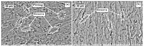
Figure 11.
Abraded surfaces of: (a) untreated 30MnCrB4 Steel {UT} and (b) conventional heat-treated (900 °C/0.67 h, water-quenched) + deep cryogenic-treated (−185 °C/12 h) 30MnCrB4 steel {CDCT-T0}.
During sliding distance of 1900 m, some particles of specimen’s material dropped out, generating pitting along with wide and deep grooves on the surface of the specimen due to their plastic deformation with the continuous and repeated ploughing action, which was responsible for large wear loss of the material [56,65]. It is clearly visible in the SEM image of UT specimen presented in Figure 11a. In SEM image of CDCT-T0 specimen, presented in Figure 11b, few shallow groove formations on the abraded surface of the specimen were observed. Number of grooves as well as depth of grooves was smaller than that in UT specimen, leading to significant improvement in the morphology of worn surface. Improvement in the hardness of the material reduced the ploughing depth, and offered stronger support for carbides to inhibit its spalling and could prevent large grooves forming during abrasive action of quartz sand. Improvement in abrasive wear behavior was due to increase in hardness, RA conversion into martensite, formation of secondary carbides, and their more uniform distribution, which ultimately led to reduction in abrasive wear volume loss [56,61,63,66,67].
3.5. Economic Analysis
Economic analysis has been done to evaluate the expected improvement in performance of rotavator blade during field operation against the additional cost quantified in Indian Rupees (Rs.) due to cryogenic treatment. The details are as follows:
| The cost of one blade (including cost of hardening) | =Rs. 215 |
| Size of rotavator | =07 Feet |
| Total number of blades | =48 |
| Weight of one blade | =1.04 Kg |
| Number of blades to be cryogenically treated in one lot | =5 × 48 = 240 |
| Additional cost for proposed cryogenic treatment on one lot | =Rs. 7800 |
| Additional cost/blade | =7800/240 = Rs. 32.50 |
| Percentage improvement in wear resistance of blade after cryogenic treatment in comparison with CHT (hardened) | =25.7% |
| Percentage increase in cost per blade due to cryogenic treatment | =15.12% |
It is evident from the economic analysis that improvement quantified in monetary terms is more that the additional cost due to cryogenic treatment. Therefore, deep cryogenic treatment processing of rotavator blades made of boron steel is recommended for improving the abrasive wear resistance and other mechanical properties.
4. Conclusions
The effect of cryogenic treatment and post-tempering on rotavator blade material were analyzed. The following conclusions were drawn:
- (1)
- During deep cryogenic treatment, retained austenite left after conventional heat treatment was transformed into martensite. Cryogenic treatment also resulted in formation of secondary carbides and helped in bringing more uniformity in distribution of secondary carbides. Tempering post cryogenic treatment led to grain coarsening and martensite decomposition;
- (2)
- Hardness of cryotreated (CDCT-T0) specimen was improved by 260.73% compared to UT material, due to the formation of martensite along with the precipitation of secondary carbides. Tempering post cryogenic treatment caused reduction in hardness due to grain coarsening and martensite decomposition;
- (3)
- Impact strength of the cryotreated (CDCT-T0) specimen was augmented by 50% in comparison with CHT specimen, due to increasing the nucleation of carbides, which facilitated the precipitation of a higher number of fine carbides during cryogenic treatment, resulting in a higher impact strength of material. Post tempering enhanced the impact strength, which further increased with higher tempering temperature;
- (4)
- Abrasive wear volume loss in cryotreated (CDCT-T0) specimens were reduced by 60% compared to UT samples, owing to improvement in hardness, RA conversion into martensite, and the formation of secondary carbides. Tempering post cryogenic treatment resulted in decline in abrasive wear resistance;
- (5)
- The additional cost of 15.12% was incurred due to cryogenic treatment, whereas the expected augmentation in wear resistance of rotavator blade material was 25.70%. The economic analysis clearly justified the additional cost of cryogenic treatment.
Author Contributions
Conceptualization, T.P.S., A.K.S., and J.S.; methodology, T.P.S, Q.S., Z.L., and K.S.; validation, M.K.G., H.J.; formal analysis, M.K.G. and T.P.S.; investigation, C.I.P., Q.S., and Z.L.; resources, Q.S., Z.L.; data curation, C.I.P., A.K.S.; writing—original draft preparation, M.K.G., H.J., and C.I.P.; writing—review and editing, Q.S., H.J.; visualization, M.K.G.; supervision, Q.S., Z.L.; project administration, C.I.P; analysis and layout; Z.L. All authors have read and agreed to the published version of the manuscript.
Funding
This research received no external funding.
Conflicts of Interest
The authors declare no conflict of interest.
References
- Saxena, A.C. Dushyant Singh Techno Economically Viable Production Package of Rotavator Blade for Entrepreneurs. Agric. Eng. Today 2010, 34, 23–25. [Google Scholar]
- Ferguson, S.A.; Fielke, J.M.; Riley, T.W. Wear of cultivator shares in abrasive South Australian soils. J. Agric. Eng. Res. 1998, 69, 99–105. [Google Scholar] [CrossRef]
- Salokhe, V.M.; Gee-Clough, D. Coating of cage wheel lugs to reduce soil adhesion. J. Agric. Eng. Res. 1988, 41, 201–210. [Google Scholar] [CrossRef]
- Salokhe, V.M.; Gee-Clough, D.; Tamtomo, P. Wear testing of enamel coated rings. Soil Tillage Res. 1991, 21, 121–131. [Google Scholar] [CrossRef]
- Kumar, S.; Mondal, D.P.; Jha, A.K. Effect of microstructure and chemical composition of hardfacing alloy on abrasive wear behavior. J. Mater. Eng. Perform. 2000, 9, 649–655. [Google Scholar] [CrossRef]
- Singh, P.; Bansal, A.; Kumar Goyal, D. Erosion wear evaluation of HVOF sprayed WC-12Co coating on some pipeline materials using Taguchi approach. Kovove Mater. 2019, 57, 113–120. [Google Scholar] [CrossRef]
- Bansal, A.; Singh, J.; Singh, H. Slurry Erosion Behavior of HVOF-Sprayed WC-10Co-4Cr Coated SS 316 Steel with and Without PTFE Modification. J. Therm. Spray Technol. 2019, 28, 1448–1465. [Google Scholar] [CrossRef]
- Karoonboonyanan, S.; Salokhe, V.M.; Niranatlumpong, P. Wear resistance of thermally sprayed rotary tiller blades. Wear 2007, 263, 604–608. [Google Scholar] [CrossRef]
- Bayhan, Y. Reduction of wear via hardfacing of chisel ploughshare. Tribol. Int. 2006, 39, 570–574. [Google Scholar] [CrossRef]
- Chahar, V.K.; Tiwari, G.S. Wear characteristics of reversible cultivator shovels treated with different surface hardening processes. J. Inst. Eng. Agric. Eng. Div. 2009, 90, 42–45. [Google Scholar]
- Raval, A.H.; Kaushal, O.P. Wear and tear of hard surfaced cultivator shovel. Agric. Mech. Asia Afr. Lat. Am. 1990, 21, 46–48. [Google Scholar]
- Moore, M.A.; McLees, V.A.; King, F.S. Hard-facing soil-engaging equipment. Agric. Eng. 1979, 34, 15–19. [Google Scholar]
- Buchely, M.F.; Gutierrez, J.C.; León, L.M.; Toro, A. The effect of microstructure on abrasive wear of hardfacing alloys. Wear 2005, 259, 52–61. [Google Scholar] [CrossRef]
- Kumar, S.; Mondal, D.P.; Khaira, H.K.; Jha, A.K. Improvement in high stress abrasive wear property of steel by hardfacing. J. Mater. Eng. Perform. 1999, 8, 711–715. [Google Scholar] [CrossRef]
- Moore, M.A. The abrasive wear resistance of surface coatings. J. Agric. Eng. Res. 1975, 20, 167–179. [Google Scholar] [CrossRef]
- Atïk, E. Mechanical properties and wear strengths in aluminiumalumina composites. Mater. Struct. Constr. 1998, 31, 418–422. [Google Scholar] [CrossRef]
- Meric, C.; Sahin, S.; Backir, B.; Koksal, N.S. Investigation of the boronizing effect on the abrasive wear behavior in cast irons. Mater. Des. 2006, 27, 751–757. [Google Scholar] [CrossRef]
- Allaoui, O.; Bouaouadja, N.; Saindernan, G. Characterization of boronized layers on a XC38 steel. Surf. Coatings Technol. 2006, 201, 3475–3482. [Google Scholar] [CrossRef]
- Béjar, M.A.; Moreno, E. Abrasive wear resistance of boronized carbon and low-alloy steels. J. Mater. Process. Technol. 2006, 173, 352–358. [Google Scholar] [CrossRef]
- Bourithis, L.; Papadimitriou, G. Boriding a plain carbon steel with the plasma transferred arc process using boron and chromium diboride powders: Microstructure and wear properties. Mater. Lett. 2003, 57, 1835–1839. [Google Scholar] [CrossRef]
- Sharma, M.C.; Mubeen, A. Effect of shot size on peening intensity for local peening. J. Mech. Work. Technol. 1983, 8, 155–160. [Google Scholar] [CrossRef]
- Singh, D.; Saxena, A.C. Characterization of Materials Used for Rotavator Blades. Agric. Eng. Today 2011, 35, 10–14. [Google Scholar]
- Yazici, A. Wear behavior of carbonitride-treated ploughshares produced from 30MnB5 steel for soil tillage applications. Met. Sci. Heat Treat. 2011, 53, 248–253. [Google Scholar] [CrossRef]
- Singh, D.; Saha, K.P.; Mondal, D.P. Development of mathematical model for prediction of abrasive wear behaviour in agricultural grade medium carbon steel. Indian J. Eng. Mater. Sci. 2011, 18, 125–136. [Google Scholar]
- Bhakat, A.K.; Mishra, A.K.; Mishra, N.S.; Jha, S. Metallurgical life cycle assessment through prediction of wear for agricultural grade steel. Wear 2004, 257, 338–346. [Google Scholar] [CrossRef]
- Gupta, A.K.; Jesudas, D.M.; Das, P.K.; Basu, K. Performance evaluation of different types of steel for duck foot sweep application. Biosyst. Eng. 2004, 88, 63–74. [Google Scholar] [CrossRef]
- Jha, A.K.; Prasad, B.K.; Modi, O.P.; Das, S.; Yegneswaran, A.H. Correlating microstructural features and mechanical properties with abrasion resistance of a high strength low alloy steel. Wear 2003, 254, 120–128. [Google Scholar] [CrossRef]
- Singla, A.K.; Singh, J.; Sharma, V.S. Processing of materials at cryogenic temperature and its implications in manufacturing: A review. Mater. Manuf. Process. 2018, 33, 1603–1640. [Google Scholar] [CrossRef]
- Kumar, T.V.; Thirumurugan, R.; Viswanath, B. Influence of Cryogenic Treatment on the Metallurgy of Ferrous Alloys - A Review. Mater. Manuf. Process. 2017, 32, 1789–1805. [Google Scholar] [CrossRef]
- Akincioğlu, S.; Gökkaya, H.; Uygur, İ. A review of cryogenic treatment on cutting tools. Int. J. Adv. Manuf. Technol. 2015, 78, 1609–1627. [Google Scholar] [CrossRef]
- Gill, S.S.; Singh, H.; Singh, R.; Singh, J. Cryoprocessing of cutting tool materials—A review. Int. J. Adv. Manuf. Technol. 2010, 48, 175–192. [Google Scholar] [CrossRef]
- Kalsi, N.S.; Sehgal, R.; Sharma, V.S. Cryogenic Treatment of Tool Materials: A Review. Mater. Manuf. Process. 2010, 25, 1077–1100. [Google Scholar] [CrossRef]
- Baldissera, P.; Delprete, C. Deep Cryogenic Treatment: A Bibliographic Review. Open Mech. Eng. J. 2008, 2, 1–11. [Google Scholar] [CrossRef]
- Yong, J.; Ding, C.; Qiong, J. Effect of cryogenic thermocycling treatment on the structure and properties of magnesium alloy AZ91. Met. Sci. Heat Treat. 2012, 53, 589–591. [Google Scholar] [CrossRef]
- Bhale, P.; Shastri, H.; Mondal, A.K.; Masanta, M.; Kumar, S.; Li, X.; Yao, Y.; Shaffer, D.; Reinstadtler, C.; Roth, J.T.; et al. Effect of Deep Cryogenic Treatment on Microstructure and Properties of AE42 Mg Alloy. J. Mater. Eng. Perform. 2016, 25, 3590–3598. [Google Scholar] [CrossRef]
- Mohan, K.; Suresh, J.A.; Ramu, P.; Jayaganthan, R. Microstructure and Mechanical Behavior of Al 7075-T6 Subjected to Shallow Cryogenic Treatment. J. Mater. Eng. Perform. 2016, 25, 2185–2194. [Google Scholar] [CrossRef]
- Steier, V.F.; Ashiuchi, E.S.; Reißig, L.; Araújo, J.A. Effect of a Deep Cryogenic Treatment on Wear and Microstructure of a 6101 Aluminum Alloy. Adv. Mater. Sci. Eng. 2016. [Google Scholar] [CrossRef]
- Singla, A.K.; Singh, J.; Kumar, P.; Kumar, A.; Sharma, V.S. Effect of cryogenic treatment on the wear resistance and microstructure of Ti-6AL-4V. Indian J. Eng. Mater. Sci. 2018, 25, 243–249. [Google Scholar]
- Singla, A.K.; Singh, J.; Sharma, V.S. Impact of Cryogenic Treatment on Mechanical Behavior and Microstructure of Ti-6Al-4V ELI Biomaterial. J. Mater. Eng. Perform. 2019, 28, 5931–5945. [Google Scholar] [CrossRef]
- Krolczyk, G.M.; Maruda, R.W.; Krolczyk, J.B.; Wojciechowski, S.; Mia, M.; Nieslony, P.; Budzik, G. Ecological trends in machining as a key factor in sustainable production—A review. J. Clean. Prod. 2019, 218, 601–615. [Google Scholar] [CrossRef]
- Mia, M.; Gupta, M.K.; Lozano, J.A.; Carou, D.; Pimenov, D.Y.; Królczyk, G.; Khan, A.M.; Dhar, N.R. Multi-objective optimization and life cycle assessment of eco-friendly cryogenic N2 assisted turning of Ti-6Al-4V. J. Clean. Prod. 2019, 210, 121–133. [Google Scholar] [CrossRef]
- Kopac, J.; Pusavec, F.; Krolczyk, G. Cryogenic machining, surface integrity and machining performance. Arch. Mater. Sci. Eng. 2015, 71, 83–93. [Google Scholar]
- Eller, T.K.; Greve, L.; Andres, M.T.; Medricky, M.; Hatscher, A.; Meinders, V.T.; Van Den Boogaard, A.H. Plasticity and fracture modeling of quench-hardenable boron steel with tailored properties. J. Mater. Process. Technol. 2014, 214, 1211–1227. [Google Scholar] [CrossRef]
- Namklang, P.; Uthaisangsuk, V. Description of microstructures and mechanical properties of boron alloy steel in hot stamping process. J. Manuf. Process. 2016, 21, 87–100. [Google Scholar] [CrossRef]
- Naderi, M. Hot Stamping of Ultra High Strength Steels; Springer International Publishing: Cham, Switzerland, 2007. [Google Scholar]
- Singh, T.P.; Singh, J.; Singh, K. An investigation on abrasive wear behaviour of rotary blade (AISI 30MnCrB4 ) under different quenching parameters. In Proceedings of the CPIE, Jalandhar, India, 19–21 December 2016. [Google Scholar]
- ASTM. E 23-12c Standard Test Methods for Notched Bar Impact Testing of Metallic Materials. Standards 2013, i, 1–25. [Google Scholar]
- ASTM. International G65-16: Standard Test Method for Measuring Abrasion Using the Dry Sand/Rubber Wheel. ASTM Stand. 2013, 4, 1–12. [Google Scholar]
- Avery, H.S. The measurement of wear resistance. Wear 1961, 4, 427–449. [Google Scholar] [CrossRef]
- Singh, T.P.; Singh, J.; Singh, K. Enhancing the abrasive wear resistance of rotary blade material (AISI 30MnCrB4) by cryogenic treatment. J. Sci. Ind. Res. 2018, 77, 92–97. [Google Scholar]
- Nahvi, S.M. Abrasive Wear Behaviour of Steels and Advanced HVOF-Sprayed WC-M Coatings. Ph.D. Thesis, University of Nottingham, Nottingham, UK, 2011. [Google Scholar]
- Moore, M.A.; Swanson, P.A. The effect of particle shape on abrasive wear: A comparison of theory and experiment. In Proceedings International Conference on Wear of Materials; Ludema, K.C., Ed.; ASME: New York, NY, USA, 1983; pp. 1–11. [Google Scholar]
- Kašparová, M.; Zahálka, F.; Houdková, S.; Ctibor, P. Abrasive wear of WC-NiMoCrFeCo thermally sprayed coatings in dependence on different types of abrasive sands. Kovove Mater. 2010, 48, 73–85. [Google Scholar]
- Singh, D.; Mondal, D.P.; Modi, O.P.; Sethi, V.K. Low stress abrasive wear response of boron steel under three body abrasion: Effect of heat treatment and peening intensities. Indian J. Eng. Mater. Sci. 2010, 17, 208–212. [Google Scholar]
- Güler, H.; Ertan, R.; Özcan, R. Influence of heat treatment parameters on the micrestructure and mechanical properties of boron-alloyed steels. Mater. Test. 2012, 54, 619–624. [Google Scholar] [CrossRef]
- Liu, H.; Wang, J.; Yang, H.; Shen, B. Effects of cryogenic treatment on microstructure and abrasion resistance of CrMnB high-chromium cast iron subjected to sub-critical treatment. Mater. Sci. Eng. A 2008, 478, 324–328. [Google Scholar] [CrossRef]
- Gola, A.M.; Ghadamgahi, M.; Ooi, S.W. Microstructure evolution of carbide-free bainitic steels under abrasive wear conditions. Wear 2017, 376–377, 975–982. [Google Scholar] [CrossRef]
- Li, H.; Tong, W.; Cui, J.; Zhang, H.; Chen, L.; Zuo, L. The influence of deep cryogenic treatment on the properties of high-vanadium alloy steel. Mater. Sci. Eng. A 2016, 662, 356–362. [Google Scholar] [CrossRef]
- Song, Z.; Zhao, S.; Jiang, T.; Sun, J.; Wang, Y.; Zhang, X.; Liu, H.; Liu, Y. Effect of nanobainite content on the dry sliding wear behavior of an Al-Alloyed high carbon steel with nanobainitic microstructure. Materials 2019, 12, 1618. [Google Scholar] [CrossRef]
- Li, S.; Xiao, M.; Ye, G.; Zhao, K.; Yang, M. Effects of deep cryogenic treatment on microstructural evolution and alloy phases precipitation of a new low carbon martensitic stainless bearing steel during aging. Mater. Sci. Eng. A 2018, 732, 167–177. [Google Scholar] [CrossRef]
- Chintha, A.R. Metallurgical aspects of steels designed to resist abrasion, and impact-abrasion wear. Mater. Sci. Technol. 2019, 35, 1133–1148. [Google Scholar] [CrossRef]
- Jaswin, M.A.; Lal, D.M. Impact Behavior of Cryogenically Treated En 52 and 21-4N Valve Steels. Int. J. Mech. Ind. Sci. Eng. 2014, 8, 159–164. [Google Scholar]
- Vuorinen, E.; Ojala, N.; Heino, V.; Rau, C.; Gahm, C. Erosive and abrasive wear performance of carbide free bainitic steels—Comparison of field and laboratory experiments. Tribol. Int. 2016, 98, 108–115. [Google Scholar] [CrossRef]
- Chand, N.; Neogi, S. Mechanism of material removal during three-body abrasion of FRP composite. Tribol. Lett. 1998, 4, 81–85. [Google Scholar] [CrossRef]
- Nadig, D.S.; Jacob, S.; Karunanithi, R.; Manjunatha, R.; Subramanian, D.; Prasad, M.V.N.; Sen, G.; Jha, A.K. Studies of cryotreatment on the performance of integral diaphragm pressure transducers for space application. Cryogenics 2010, 50, 561–565. [Google Scholar] [CrossRef]
- Vuorinen, E.; Heino, V.; Ojala, N.; Haiko, O.; Hedayati, A. Erosive-abrasive wear behavior of carbide-free bainitic and boron steels compared in simulated field conditions. Proc. Inst. Mech. Eng. Part J J. Eng. Tribol. 2018, 232, 3–13. [Google Scholar] [CrossRef]
- Hernandez, S.; Leiro, A.; Rodríguez, M.; Vuorinen, E.; Sundin, K.; Prakash, B. High temperature three-body abrasive wear of 0.25C 1.42Si steel with carbide free bainitic (CFB) and martensitic microstructures. Wear 2016, 360–361, 21–28. [Google Scholar] [CrossRef]


© 2020 by the authors. Licensee MDPI, Basel, Switzerland. This article is an open access article distributed under the terms and conditions of the Creative Commons Attribution (CC BY) license (http://creativecommons.org/licenses/by/4.0/).