Article

Temperature-Related Corrosion Resistance of AISI 1010 Carbon Steel in Sulfolane

1
Institute of Materials Engineering, University of Silesia in Katowice, 75 Pulku Piechoty 1A, 41-500 Chorzow, Poland
2
Institute of Chemistry, University of Silesia in Katowice, Szkolna 9, 40-007 Katowice, Poland
*
Authors to whom correspondence should be addressed.
Materials 2020, 13(11), 2563; https://doi.org/10.3390/ma13112563
Submission received: 9 April 2020 / Revised: 15 May 2020 / Accepted: 1 June 2020 / Published: 4 June 2020
(This article belongs to the Special Issue Corrosion and Corrosion Inhibition of Metals and Their Alloys)

Abstract

:
Sulfolane-induced corrosion can lead to severe impairment in industrial systems. Therefore, determination of solvent corrosivity is valid. Under standard conditions, pure sulfolane is considered to be thermally stable and chemically inert, hence non-aggressive towards carbon/stainless steel. Unfortunately, the sulfolane-evoked corrosion of the industrial installations is observed for sulfolane-based systems polluted by small quantities of oxygen, water and some oxidizing agents. Moreover, sulfolane decomposition with formation of corrosive (by-)products can be escalated by some process parameters, e.g., temperature. The main objective of this study was to determine the corrosion resistance of AISI 1010 steel immersed in sulfolane at temperatures ranging from 25 to 230 °C. Evaluation of the corrosion damage was carried out using electrochemical techniques and scanning probe/electron microscopy, respectively. The general corrosion tendency, corrosion rate and surface corrosion degree were taken into account as well. It was noticed that the corrosion rate linearly increases with the enhancement of sulfolane temperature. Moreover, the interfacial reaction of steel with sulfolane resulted in the formation of corrosion product layer, which is a physical barrier between the corrosive environment and steel improving corrosion resistance of the latter. In fact, the increment of the sulfolane temperature caused a gradual breakdown of the protective layer and the increase in the corrosion degree of the investigated steel. Finally, it was found that the corrosion degree doubles approximately every 42 °C.

1. Introduction

A worldwide rise of atmospheric pollution due to the expansion of industrial/agricultural areas and urban settlements is a peculiar ‘landmark’ of the modern civilization. The global ecosystem is being confronted with volatile organic compounds (VOCs) as well as inorganic odorous compounds (VICs) that pose hazards to the health of human beings and plants vegetation forming a significant part of indoors/outdoors pollution [1,2,3]. The individual sulfur derivatives exert some irritant and toxic effects, being classified as a potential mutagenic and carcinogenic risk factors [4]. In particular, a valid subset of air/water/soil pollutants, composed of sulfur-containing derivatives and their metabolites, namely ‘old devils of green chemistry’, has detrimental impact on human health following long-term exposure [5]. The demand for environmental protection and necessity to diminish the ecosystem burden is the major driving force that pushes the industry decision-makers to develop and/or optimize the sustainable, operationally simple manufacturing technologies; however, some industrially-engineered solvents are still harmful to nature [6]. The reduction of sulfur-based compounds (RSCs) from the unprocessed natural/industrial off-gasses can be achieved in a liquid/liquid or liquid/vapor extraction processes, although the design of the ‘green’ solvents and cost-effective, large-scale procedures represents a relevant challenge [7].
An appealing alternative to extensively employed extractive liquids in the dearomatization of petroleum fractions or sweetening of sour gases in the petrol-related industry is sulfolane (SFL) [8]. Although the spelling ‘sulfolane’ may be astonishing for British English users this name has been accepted as the generic name for hydrogenated sulfones of butadiene with a four-membered carbon ring and sulfonyl functional group (=SO2) [9]. On the other hand, sulfolane is also known under a variety of synonyms/numbers including thiolane 1,1-dioxane (IUPAC), 2,3,4,5-tetrahydrothiophene-1,1-dioxide (systematic), thiocyclopentane-1,1-dioxide, (cyclo) tetramethylene sulphone, dihydrobutadiene sulphone, sulphoxaline, 126-33-0 (CAS) or 204-783-1 (EINECS), respectively. SFL (C4H8O2S) is a versatile dipolar aprotic solvent with a high oxidation potential (> 6.35 V) that is highly soluble in water (1.266 × 10⁶ mg/L at 20 °C) [10,11]. Unfortunately, the extensive SFL production and usage in industry has brought an increase in issues with liquid storage security; unintended leakage from extraction units in refineries or gas plants into the surrounding environment proved inevitable, severely affecting the ecology of neighboring areas [12]. Once in the environment, SFL is vulnerable to long-distance movement into groundwater and subsequent migration to domestic wells, deteriorating water sensory properties [13]. Due to restricted data pertaining to absorption, distribution, metabolism, excretion and toxicity (ADME-Tox) related to acute inhalation or intraperitoneal exposure to SFL-rich aqueous solutions, the sulfolane-based liquids in the environmental/biological systems were targeted for extensive scrutiny [14]. Potential neurotoxicity of dose-related SFL/water mixtures was investigated in the inhalation studies of aerosolized liquid in various rodent species [15]. The fate of well-absorbed radio-labeled [2,5-14C] or [3H] or [35S] sulfolane was monitored to specify in vivo metabolic path(s) of unchanged sulfolane content or its metabolites following oral/intravenous/dermal administration. Since the toxicokinetic pattern of SFL disposition and clearance cannot be directly foreseen in the human body based on the quantitative ADME-Tox rodent models, it is therefore still not clear whether SFL can be regarded as ‘magic extractor or bad actor’ [16,17]. In this context, it is natural to raise a question about environmentally friendly and low-cost chemical and/or biological protocols for treatment of SFL contaminated groundwater or soil wash water. The operational parameters for bioremediation potential of indigenous microbes at the polluted site were scrutinized revealing that the efficiency of SFL biodegradation is strongly dependent on the dissolved oxygen (DO) level according to the aerobic mineralization formula [18]:
C 4 H 8 O 2 S + 6.5 O 2 4 CO 2 + 3 H 2 O + 2 H + + SO 4 2
The application of a bio-augmentation strategy that assumes the employment of co-aggregated bacterial consortia considerably improved the SFL removal [19]. The nutritional supplement of diverse microbial communities should be controlled at the sufficient C:N:P ratio level to ensure the enhanced in situ degradation of the target pollutant. In other words, moderate temperature and proper addition of bio-stimulating agents that increase the concentration of the biomass in the system seem to refine SFL bioremediation capability. Ex situ soil washing conjugated with the advanced oxidation processes (AOPs) were applied for the purification of SFL-containing soil wash water using the strong oxidizing potential of hydroxyl radicals (·OH) [20]. A multitude of processes for ·OH radical generation makes the AOPs approach an attractive alternative to the conventional SFL/water treatment methods. The impact of experimental parameters including water/soil ratio, number of extraction cycles or shaking time was analyzed for the synthetic (model) water and the real SFL-contaminated groundwater samples [21]. The oxidation-related treatment of SFL-polluted soil wash water was performed using UV/H2O2, UV/O3, alkaline ozonation and neutral Fenton reagents coupled with pH, chemical dosage of H2O2 and ethylenediaminetetraacetic acid chelated iron (FeEDTA), O3 flow rate and ultraviolet-C light controlling, respectively. The removal efficiency (RE) of SFL pollutant (>99%) transferred (82–93%) to aqueous phase was found for the scrutinized water/soil fractions along with mixing periods employing UVC irradiation and adequate H2O2 concentration (200 mg/L in undiluted sample), whereas neutral Fenton reagents performed pretty poorly (RE < 50%) [22]. It seems that AOPs revealed noticeable potential to degrade SFL in the contaminated water with the generation of non-toxic (by-)products and comprehensive SFL mineralization [23].
Due to shortcomings and operational costs of SFL-polluted soil/water treatment a question naturally appears about the main causes for unforeseen/accidental SFL leakage, as it is known that pure liquid is non-aggressive to steel under the standard operating conditions [24]. Unfortunately, the SFL-induced corrosion of the industrial installations is observed for SFL-based systems polluted by small quantities of oxygen, water and oxidizing agents such as chlorates, nitrates or peroxides [25]. Moreover, the SFL decomposition with formation of corrosive (by-)products can be escalated by some process parameters, e.g., temperature [26]. The sulfolane synthesis, application of sulfolane as an extractive solvent due to its ‘unique’ physicochemical properties, the potential of sulfolane to cause equipment corrosion and subsequent spills, the possible risk for groundwater contamination, danger for human health and ways of sulfolane biodegradation are reviewed briefly in our previous works [16,25].
It should be emphasized that there is a gap on the path leading from data to knowledge pertaining to the detailed quantitative assessment of the effect exerted by individual impurities or operational variables on the SFL-induced corrosion of carbon and alloyed steels. In fact, carbon steel is quite commonly used in the oil and gas industry due to its availability, constructability and relative low cost of production. On the other hand, the susceptibility to corrosion (low corrosion resistance) imposes boundaries on the practical longevity of carbon steel applications, petrochemical pipes are especially prone to corrosion damage due to the erosive/corrosive nature of the produced fluids or gases [26]. Thus, the principal objective of the presented study was to analyze the impact of sulfolane temperature on general corrosion tendency, corrosion rate and corrosion degree of AISI 1010 steel.

2. Materials and Methods

2.1. Set for Corrosion of AISI 1010 Steel in Sulfolane

The test material was AISI 1010 low carbon steel in the annealed state containing 0.1 wt.% C. Before the corrosion test, the steel samples were degreased in acetone. The corrosion process of as-obtained AISI 1010 steel (89 × 20 × 2 mm3) in sulfolane (chemically pure ≥ 99%, ≤ 0.2 vol.% of water) was conducted in a home-made sealed vessel. The detailed description of the vessel construction and the equipment used in corrosion test can be found elsewhere [25]. The sulfolane temperature was set to 25, 95, 180 and 230 °C. For each temperature the immersion time was 96 h. To reduce contact of sulfolane with air, a protective layer of inert gas (99.995% Ar) was formed over its surface. After 96 h of experiment, the vessel was cooled and the AISI 1010 steel electrodes were disassembled and rinsed in acetone.

2.2. Electrochemical Tests of AISI 1010 Steel

A series of electrochemical tests were carried out for AISI 1010 steel covered with corrosion products formed after 96 h of immersion in the sulfolane at temperatures of 25, 95, 180 and 230 °C. Measurements were conducted in a thermostated three-electrode cell filled with sulfolane at the temperature of 25 °C using electrochemical system PARSTAT 2273 (Princeton Applied Research, Oak Ridge, TN, USA). Working and counter electrodes were AISI 1010 steel and platinum plates with geometric surface areas of 8 and 100 cm2, respectively. The reference electrode was a saturated calomel electrode (SCE) placed ca. 0.2 cm from the working electrode using a Luggin capillary. Ohmic drop ΔE = jRS (V) was estimated using measured current density (j) and solution resistance (Rs). Solution resistance was calculated using equation Rs = −1 (Ω·cm2) where l is the distance between Luggin capillary and AISI 1010 steel surface (0.2 cm), κ is the sulfolane conductivity (0.35 μS·cm−1 at 25 °C [27]). The sulfolane resistance was equal to 0.57 MΩ·cm2. The open circuit potential (OCP) was registered for 60 min. Next, polarization curves j = f(E) (E is the electrode potential) were recorded in the range ± 150 mVSCE versus OCP using the linear sweep voltammetry technique with the potential sweep rate v = 10 mV·min−1. Using j = f(E) curves with compensated ohmic drop and equation:
j = j corr { e [ ln 10 ( E E corr ) β a ] e [ ln 10 ( E E corr ) β c ] }
corrosion current density (jcorr), corrosion potential (Ecorr) as well as anodic (βa) and cathodic (βc) Tafel slopes were determined. In addition, the Stern-Geary coefficient (B), polarization resistance (Rp) and corrosion rate (CR) were calculated according to the following equations:
B = β a β c ln 10 ( β a + β c )
R p = B j corr
C R = k E W ρ j corr
where ρ is the material density, EW is the material equivalent weight and k is a coefficient which determines the unit of corrosion rate. For the investigated AISI 1010 steel electrodes ρ = 7.86 g·cm−3, EW = 27.923 (valence for Fe was assumed as 2) and k = 3.27·10−3 mm·g·μA−1·cm−1·year−1, which gives the corrosion current density expressed in μA·cm−2 corrosion rate in mm·year−1. Note that low value of the sulfolane conductivity at 25 °C causes the measured current to be very small, i.e., in the of order of nanoamps or smaller, which may lead to some noise. Therefore, to visualize and interpret the obtained data more accurately, noise was removed using Savitzky-Golay smoothing algorithm [28] and OriginPro 2018 software (OriginLab, Northampton, MA, USA).

2.3. Surface Analysis of AISI 1010 Steel

Qualitative and quantitative surface analysis of AISI 1010 steel electrodes was carried out using scanning electron microscope (SEM) JEOL JSM-6480 (JEOL Ltd., Tokyo, Japan), equipped with an energy dispersive X-ray spectroscopy (EDS, JEOL Ltd., Tokyo, Japan). Obtained SEM images were converted to black and white (black color corresponds to the corroded areas) and next the corrosion degree (CD) was calculated according to the following equation:
C D = total   corroded   area total   area   of   an   image 100 %
The EDS technique allowed to determine the distribution of iron and carbon elements on the surface of AISI 1010 steel.
Contact potential difference (CPD) maps were registered for the studied electrodes using a scanning electrochemical workstation PAR M370 (Princeton Applied Research, Oak Ridge, USA) equipped with a tungsten Kelvin probe (KP, ø500 μm, Princeton Applied Research, Oak Ridge, USA). The scanning area was 4 × 4 mm2 and the distance between the sample and the probe was c.a. 90 μm. Approximation of the histograms of the CPD values using Gaussian function given by the equation:
g ( C P D ) = 1 σ 2 π e 1 2 ( C P D C P D av σ ) 2
allowed to estimate the average value of contact potential difference (CPDav) and its standard deviation (σ) that describe quantitatively the material surface properties. The detailed description of the preparation of histograms can be found elsewhere [29,30].

3. Results and Discussion

3.1. Corrosion Resistance Analysis of AISI 1010 Steel

Variations of the OCP measured for AISI 1010 steel electrodes in sulfolane for 60 min are illustrated in Figure 1. Using OCP = f(t) curves, the average values of OCP and corresponding standard errors (SE) were determined and are reported in Table 1. One can observe that the average value of OCP decreases with increased sulfolane temperature. In particular, when the temperature increases from 25 to 230 °C, the OCP value decreases by ca. 175 mVSCE and the steel electrode reaches the most negative potential among all tested. Such behavior indicates an increase in the thermodynamic tendency to the corrosion process, thus deterioration of corrosion resistance of AISI 1010 steel. It was found that, up to about 180 °C, standard errors of the mean decrease and then increase, which may be caused by sulfolane decomposition at temperatures over 200 °C. On the one hand, sulfolane decomposition increases the corrosiveness of the environment. On the other hand, the heterogeneity of the surface geometry and/or chemical composition causes that some of its areas are more electrochemically active than others. These two factors generate some distribution of the potential on the material surface. It should be added that corrosion product layer influences the electrochemical parameters as well. Nevertheless, after 60 min relatively stable value of open circuit potential can be observed for all the investigated electrodes.
Polarization curves for the AISI 1010 steel electrodes immersed in sulfolane at 25, 95, 180, and 230 °C are shown in Figure 2, while electrochemical parameters obtained using registered curves and Equation (2) are reported in Table 2.
Corrosion potential is a thermodynamic value that provides the information about the corrosion tendency of the material in a specific environment, while corrosion current density (jcorr) is a kinetic value which is proportional to the corrosion rate (CR) (see Equation (5)). It was found that for the AISI 1010 steel electrodes immersed in sulfolane corrosion potential (Ecorr) corresponds to the open circuit potential. It was also stated that for a sulfolane temperature equal to 230 °C, the value of corrosion current density for tested steel is only ca. 7.5 nA·cm−2, which corresponds to a corrosion rate of 87 nm·year−1. However, an increase in the sulfolane temperature from 25 to 230 °C causes ca. 2.8-fold higher corrosion rate. Parameters jcorr and CR as a function of sulfolane temperature (T) are shown in Figure 3. One can see that both jcorr = f(T) and CR = f(T) dependencies are linear with the slopes of 0.29(2) nm·year−1/°C and 0.025(1) nA·cm−2/°C, respectively. The calculated slopes can be interpreted as the rate of change of jcorr and CR per degree Celsius. The obtained values of Ecorr, jcorr and CR indicate that the tendency to corrosion and corrosion rate of AISI 1010 steel increase with increased sulfolane temperature.
Generally, the decomposition temperature of sulfolane is ca. 230 °C. However, slow thermal decomposition with the formation of sulphur dioxide and butadiene already occurs at temperatures above 200 °C. Surprisingly, high decomposition rates may occur at temperatures of 175–190 °C for sulfolane contaminated with oxygen [24,31]. In the absence of water, sulphur dioxide does not react strongly with carbon steel however, in the presence of water and oxygen it forms highly corrosive sulfurous acid according to the following formula:
C 4 H 8 O 2 S + O 2 + H 2 O H 2 SO 3 + C 3 H 7 CO 2 H
The calculated βa and βc values (see Table 2) indicate that for all investigated electrodes the rate determining step of the corrosion is the anodic process. For AISI 1010 steel electrodes anodic process can be associated with the iron oxidation:
Fe 2 e Fe 2 +
Taking into account Equation (8), the cathodic process coupled with the anodic may be the reduction of H+ ions:
2 H + + 2 e H 2
Using Equations (3) and (4) the Stern–Geary coefficients (B) and polarization resistance (Rp) were calculated and are shown in Table 2. One can see that for the AISI 1010 steel electrode immersed in sulfolane at 25 °C, the B value is equal to 25 mV, which corresponds to the active corrosion state. However, for electrodes immersed in sulfolane at 95, 180 and 230 °C, relatively high values of the parameter B (70–130 mV) were obtained, indicating the passive corrosion state for those materials. This fact can be explained by the reaction of carbon steel with sulphurous acid during the corrosion process. It causes the formation of ferrous sulfite (FeSO3), which adheres to the steel surface and forms a layer that protects the alloy against further corrosion attack. Note that all obtained Rp values are of the order of MΩ·cm2. However, the highest polarization resistance was determined for the electrode immersed at 95 °C. The obtained results indicate that the protective layer formed on the surface of the AISI 1010 steel may be a physical barrier between the corrosive environment and the material improving the corrosion resistance of the latter. Nevertheless, an increase in the sulfolane temperature to 180 °C and next to 230 °C cause breakdown of the protective layer and increase in the corrosion degree.

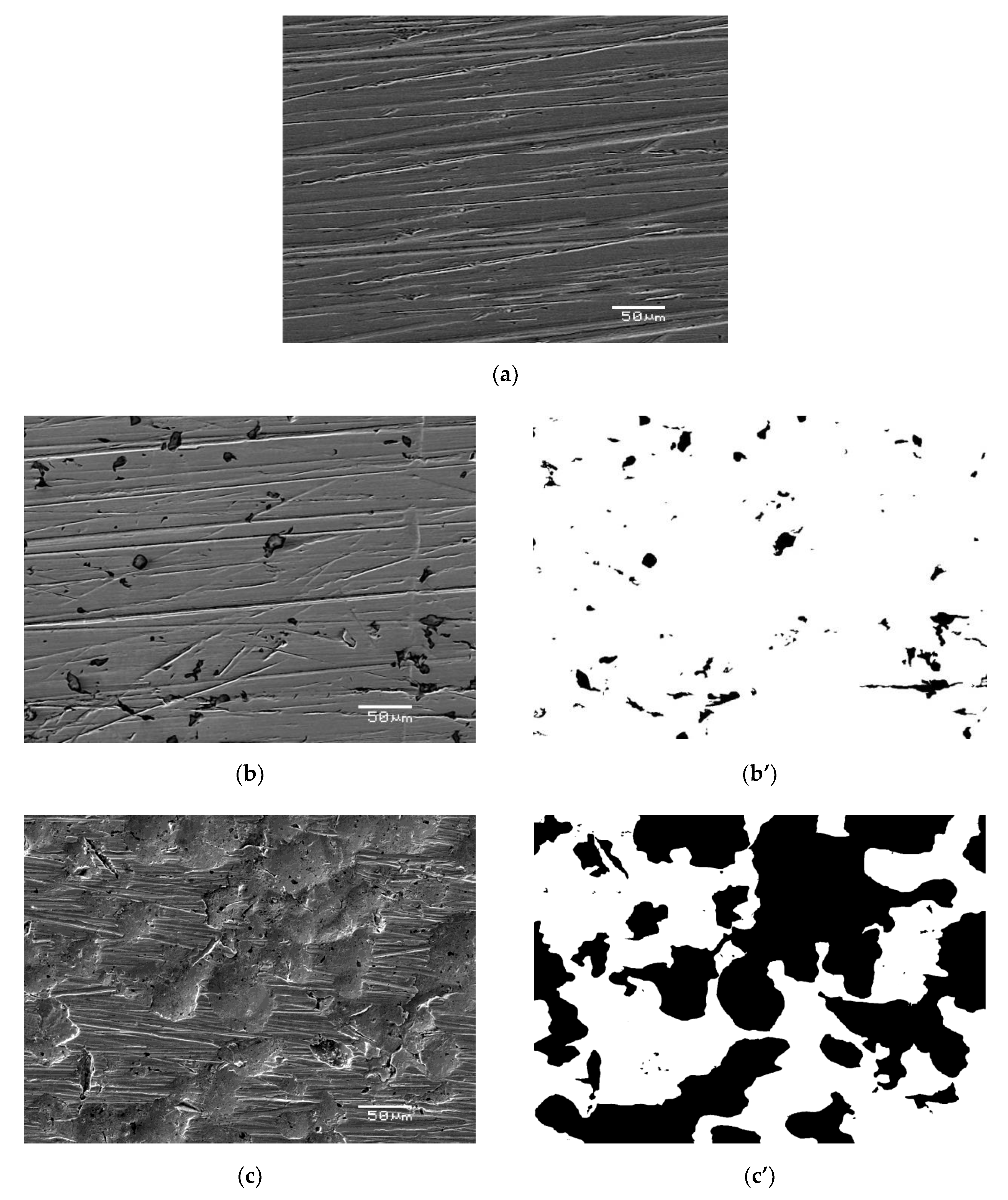
3.2. Surface Analysis of AISI 1010 Steel

The SEM/EDS images of the AISI 1010 steel surface without etching of corrosion products are shown in Figure 4 and Figure 5, respectively. For all investigated electrodes one can see numerous defects of different size and depth. Corrosion degree (CD) of AISI 1010 steel electrodes was estimated using SEM images and corresponding black and white images shown in Figure 4. As shown in Figure 6, the higher the temperature, the higher the corrosion degree. It was found that the corrosion degree of AISI 1010 steel immersed in sulfolane doubles approximately every 42 °C. Temperature increase leads to a higher corrosion rate (and hence higher corrosion degree) because cathodic and anodic reactions occur faster (see the βa and βc values in Table 2). Figure 5 shows distribution maps of iron and carbon elements on the AISI 1010 steel surface (without etching of corrosion products). The maps show that iron and carbon elements are homogeneously distributed on the material surface. However, the areas affected by corrosion are characterized by lower local amount of iron, which is obvious considering that it dissolves in such areas (see Equation (9)).
Contact potential difference (CPD) maps for the AISI 1010 steel electrodes are shown in Figure 7a–d. For each map, a corresponding histogram was prepared, as illustrated in Figure 8. Fitting the histograms with the Gaussian function (Equation (7)) allowed to quantify the material surface properties. In particular, it enabled to determine the average value of contact potential difference (CPDav) and its standard deviation σ that are reported in Table 3.
The AISI 1010 steel electrode immersed in sulfolane at 25 °C (Figure 7a) is characterized by about 100 mVKP lower CPDav in comparison with the sample immersed in sulfolane at 95 °C (Figure 7b). Note that the sample immersed in sulfolane at 95 °C has the highest CPDav value among all the investigated electrodes. This can be explained by the fact that a certain layer of corrosion product is formed on the electrode surface. However, further increase in the temperature (to 180 and 230 °C) results in the discontinuities of the corrosion product layer and a decrease in CPDav value (see Figure 7c,d). AISI 1010 steel electrode immersed in sulfolane at 230 °C (Figure 7d) is characterized by the smallest value of CPDav. Moreover, CPDav and Rp as a function of temperature are characterized by a similar trend. It was also found that the spread of the CPD distribution from the average (represented by σ, Table 3) is the smallest for the AISI 1010 steel electrode immersed in sulfolane at 95 °C and increases with increased temperature. The obtained results show that the AISI 1010 steel electrode immersed in sulfolane at 95 °C is characterized by the most uniform surface among all the investigated electrodes.

4. Conclusions

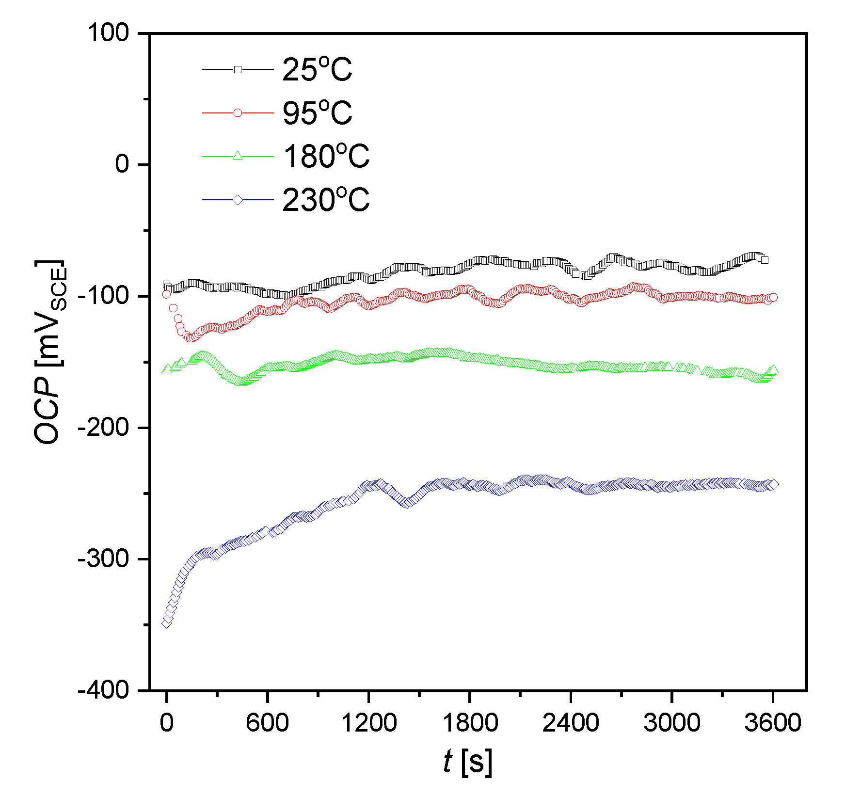
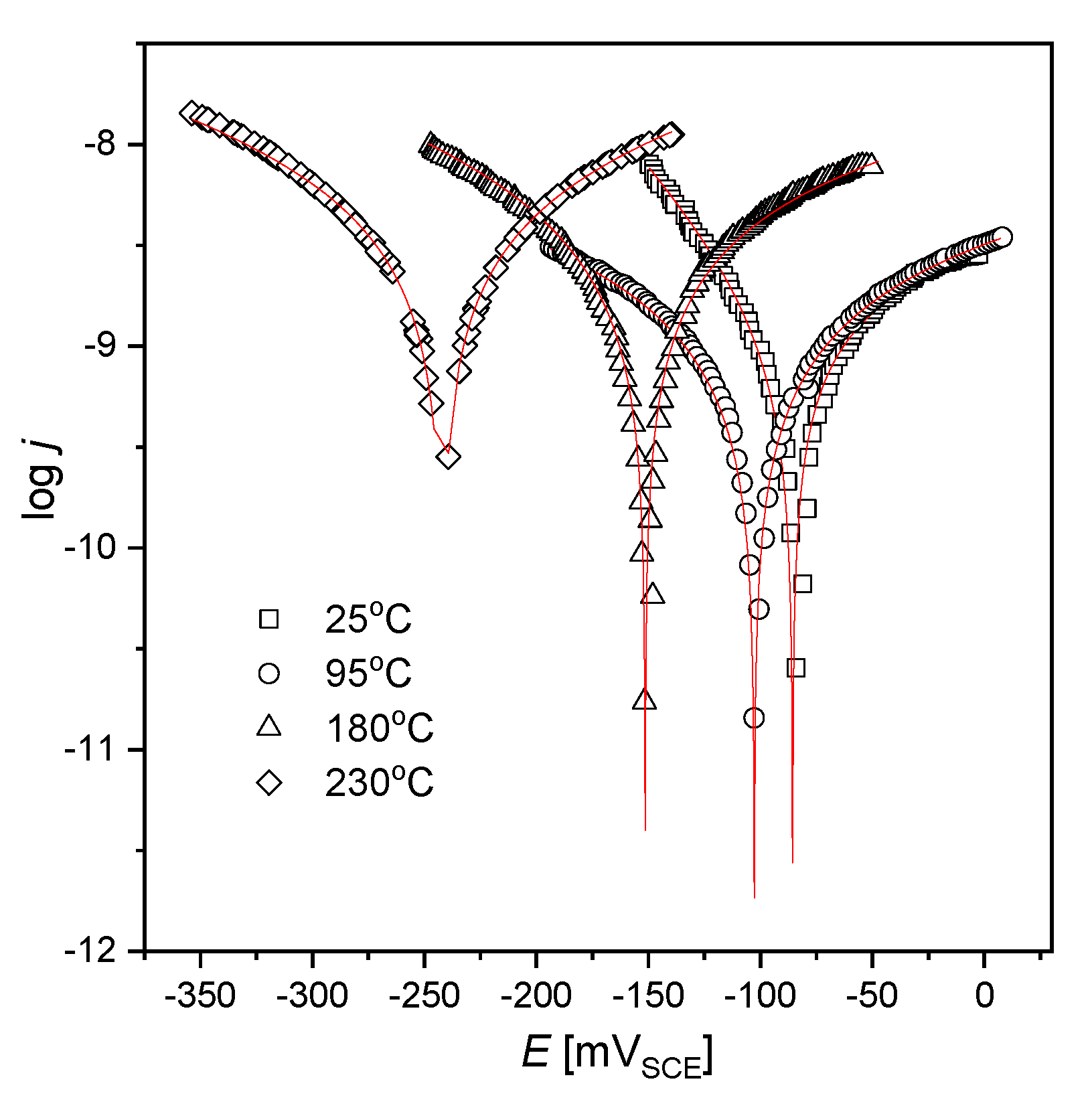
  • Thermodynamic tendency for the corrosion process, as well as the corrosion rate of the AISI 1010 steel, increase with increased sulfolane temperature. In particular, an increase in the sulfolane temperature from 25 to 230 °C results in a decrease in corrosion potential value by ca. 175 mV (Figure 1, Table 1) and, simultaneously, a 2.8-fold increase in the corrosion rate (Figure 3, Table 2).
  • The highest polarization resistance (Table 2) and average contact potential difference (Table 3) were found for the AISI 1010 steel immersed in sulfolane at 95 °C; thus this electrode is characterized by the most compact and uniform surface among all the investigated ones.
  • The corrosion product layer formed on the surface of the AISI 1010 steel electrodes in sulfolane is a physical barrier between the corrosive environment and the material and partially protects the alloy against further corrosion attack.
  • An increase in the sulfolane temperature caused a gradual breakdown of the protective layer and an increase in the corrosion degree. It was found that the corrosion degree of AISI 1010 steel immersed in sulfolane doubles approximately every 42 °C (Figure 6).

Author Contributions

J.K., B.Ł., V.K., A.B.,—conceptualization, methodology, investigation, formal analysis, article writing and editing, P.D.,—data curation, article editing. All authors have read and agreed to the published version of the manuscript.

Funding

This research received no external funding.

Acknowledgments

We would like to profoundly acknowledge Honeywell Process Solutions for any help.

Conflicts of Interest

The authors declare no conflict of interest.

References

  1. Curtis, L.; Rea, W.; Smith-Willis, P.; Fenyves, E.; Pan, Y. Adverse health effects of outdoor air pollutants. Environ. Int. 2006, 32, 815–830. [Google Scholar] [CrossRef] [PubMed]
  2. Atkinson, R.; Arey, J. Atmospheric degradation of volatile organic compounds. Chem. Rev. 2003, 103, 4605–4638. [Google Scholar] [CrossRef] [PubMed]
  3. Barro, R.; Regueiro, J.; Llompart, M.; Garcia-Jares, C. Analysis of industrial contaminants in indoor air: Part 1. Volatile organic compounds, carbonyl compounds, polycyclic aromatic hydrocarbons and polychlorinated biphenyls. J. Chromatogr. A 2009, 1216, 540–566. [Google Scholar] [CrossRef] [PubMed]
  4. Huang, Y.; Ho, S.S.H.; Lu, Y.; Niu, R.; Xu, L.; Cao, J.; Lee, S. Removal of indoor volatile organic compounds via photocatalytic oxidation: A short review and prospect. Molecules 2016, 21, 56. [Google Scholar] [CrossRef] [Green Version]
  5. Bak, A.; Kozik, V.; Dybal, P.; Sulowicz, S.; Kasperczyk, D.; Kus, S.; Barbusinski, K. Abatement robustness of volatile organic compounds using compact trickle-bed bioreactor: Biotreatment of styrene, ethanol and dimethyl sulfide mixture in contaminated airstream. Int. Biodeterior. Biodegr. 2017, 119, 316–328. [Google Scholar] [CrossRef]
  6. Wagh, R.B.; Gund, S.H.; Nagarkar, J.M. An eco-friendly oxidation of sulfide compounds. J. Chem. Sci. 2016, 128, 1321–1325. [Google Scholar] [CrossRef] [Green Version]
  7. Angaji, M.T.; Ghanbarabadi, H.; Gohari, F.K.Z. Optimizations of sulfolane concentration in propose Sulfinol-M solvent instead of MDEA solvent in the refineries of Sarakhs. J. Nat. Gas Sci. Eng. 2013, 15, 22–26. [Google Scholar] [CrossRef]
  8. Tilstam, U. Sulfolane: A versatile dipolar aprotic solvent. Org. Process Res. Dev. 2012, 16, 1273–1278. [Google Scholar] [CrossRef]
  9. Zaretskii, M.I.; Rusak, V.V.; Chartov, E.M. Sulfolane and dimethyl sulfoxide as extractants. Coke Chem. 2013, 56, 266–268. [Google Scholar] [CrossRef]
  10. Shah, S.M.; Wahba, M.; Yu, L.; Achari, G.; Habibi, H.R. Health impact assessment of sulfolane on embryonic development of zebrafish (Danio rerio). Toxics 2019, 7, 42. [Google Scholar] [CrossRef] [Green Version]
  11. Wang, S.; Wei, C.; Ding, W.; Zou, L.; Gong, Y.; Liu, Y.; Zang, L.; Xu, X. High-voltage sulfolane plasticized UV-curable gel polymer electrolyte. Polymers 2019, 11, 1306. [Google Scholar] [CrossRef] [PubMed] [Green Version]
  12. Saint-Fort, R. Sulfolane attenuation by surface and subsurface soil matrices. J. Environ. Sci. Health A 2006, 41, 1211–1231. [Google Scholar] [CrossRef] [PubMed]
  13. Kasanke, C.P.; Leight, M.B. Factors limiting sulfolane biodegradation in contaminated subarctic aquifer substrate. PLoS ONE 2017, 12, 1–10. [Google Scholar] [CrossRef] [PubMed] [Green Version]
  14. Thompson, C.M.; Gaylor, D.W.; Tachovsky, J.A.; Perry, C.; Caracostas, M.C.; Haws, L.C. Development of a chronic noncancer oral references dose and drinking water screening level for sulfolane using benchmark dose modelling. J. Appl. Toxicol. 2013, 33, 1395–1406. [Google Scholar] [CrossRef] [PubMed]
  15. Waidyanatha, S.; Black, S.R.; Blystone, C.R.; Patel, P.R.; Watson, S.L.; Snyder, R.W.; Fennell, T.R. Disposition and metabolism of sulfolane in Harlan Sprague Dawley rats and B6C3F1/N mice and in vitro in hepatocytes from rats, mice, and humans. Xenobiotica 2020, 4, 442–453. [Google Scholar] [CrossRef]
  16. Bak, A.; Kozik, V.; Dybal, P.; Kus, S.; Swietlicka, A.; Jampilek, J. Sulfolane: Magic extractor or bad actor? Pilot-scale study on solvent corrosion potential. Sustainability 2018, 10, 3677. [Google Scholar] [CrossRef] [Green Version]
  17. Silinski, M.A.R.; Uenoyama, T.; Cooper, S.D.; Fernando, R.A.; Robinson, V.G.; Waidyanatha, S. Development and validation of an analytical method for quantitation of sulfolane in rat and mouse plasma by GC–MS. J. Anal. Toxicol. 2019, 43, 477–481. [Google Scholar] [CrossRef]
  18. Yang, C.F.; Liu, S.H.; Su, Y.M.; Chen, Y.R.; Lin, C.W.; Lin, K.L. Bioremediation capability evaluation of benzene and sulfolane contaminated groundwater: Determination of bioremediation parameters. Sci. Total Environ. 2019, 648, 811–818. [Google Scholar] [CrossRef]
  19. Khan, M.F.; Yu, L.; Tay, J.H.; Achari, G. Coaggregation of bacterial communities in aerobic granulation and its application on the biodegradation of sulfolane. J. Hazard. Mater. 2019, 377, 206–214. [Google Scholar] [CrossRef]
  20. Izadifard, M.; Achari, G.; Langford, C.H. Mineralization of sulfolane in aqueous solutions by Ozone/CaO2 and Ozone/CaO with potential for field application. Chemosphere 2018, 197, 525–540. [Google Scholar] [CrossRef]
  21. Izadifard, M.; Achari, G.; Langford, C.H. Degradation of sulfolane using activated persulfate with UV and UV-Ozone. Water Res. 2017, 125, 325–331. [Google Scholar] [CrossRef]
  22. Brandão, M.; Yu, L.; García, C.; Achari, G. Advanced oxidation based treatment of soil wash water contaminated with sulfolane. Water 2019, 11, 2152. [Google Scholar] [CrossRef] [Green Version]
  23. Karimi, B.; Ghoreishi-Nezhad, M.; Clark, J.H. Selective oxidation of sulfides to sulfoxides using 30% hydrogen peroxide catalyzed with a recoverable silica-based tungstate interphase catalyst. Org. Lett. 2005, 7, 625–628. [Google Scholar] [CrossRef] [PubMed]
  24. Schneider, D.F. Avoid sulfolane regeneration problems. Chem. Eng. Progress 2004, 100, 34–39. [Google Scholar]
  25. Bak, A.; Losiewicz, B.; Kozik, V.; Kubisztal, J.; Dybal, P.; Swietlicka, A.; Barbusinski, K.; Kus, S.; Howaniec, N.; Jampilek, J. Real-time corrosion monitoring of AISI 1010 carbon steel with metal surface mapping in sulfolane. Materials 2019, 12, 3276. [Google Scholar] [CrossRef] [PubMed] [Green Version]
  26. Mutahfar, F.; Aithan, G.; Iski, E.V.; Keller, M.W.; Shirazi, S.; Roberts, K.P. 31-Mechanistic modeling of erosion–corrosion for carbon steel. In Trends in Oil and Gas Corrosion Research and Technologies; El-Sherik, A.M., Ed.; Elsevier: London, UK, 2017; pp. 749–763. ISBN 9780081011058. [Google Scholar]
  27. Mingy, L.; Zhong, J.; Xujiang, S. Cause of equipment corrosion and counter measures in the sulfolane recycling system of aromatics extraction unit. Pet. Process Pe. 2005, 36, 30–33. [Google Scholar]
  28. Press, W.H.; Teukolsky, S.A.; Vetterling, W.T.; Flannery, B.P. Numerical Recipes: The Art of Scientific Computing, 3rd ed.; Cambridge University Press: Cambridge, UK, 2007; ISBN 9780521884075. [Google Scholar]
  29. Kubisztal, J.; Kubisztal, M.; Haneczok, G. Quantitative characterization of material surface – application to Ni + Mo electrolytic composite coatings. Mater. Charact. 2016, 122, 45–53. [Google Scholar] [CrossRef]
  30. Kubisztal, J.; Kubisztal, M.; Stach, S.; Haneczok, G. Corrosion resistance of anodic coatings studied by scanning microscopy and electrochemical methods. Surf. Coat. Tech. 2018, 350, 419–427. [Google Scholar] [CrossRef]
  31. Othmer, K. Encyclopedia of Chemical Technology, 4th ed.; John Wiley & Sons: Hoboken, NJ, USA, 2001; ISBN 9780471238966. [Google Scholar]
Figure 1. Open circuit potential for the AISI 1010 steel electrodes immersed in sulfolane at 25, 95, 180, and 230 °C; VSCE is the electrode potential measured versus saturated calomel electrode.
Materials 13 02563 g001
Figure 2. Polarization curves for the AISI 1010 steel electrodes immersed in sulfolane at 25, 95, 180, and 230 °C; symbols—experimental data, solid lines—fit of the Equation (2); VSCE is the electrode potential measured versus saturated calomel electrode.
Materials 13 02563 g002
Figure 3. Corrosion current density (jcorr) and corrosion rate (CR) for the AISI 1010 steel electrodes immersed in sulfolane at 25, 95, 180, and 230 °C.
Materials 13 02563 g003
Figure 4. Exemplary scanning electron microscope (SEM) images for the AISI 1010 steel electrode in initial state (a) and immersed in sulfolane at 95 °C [25] (b) and 230 °C (c) as well as corresponding black and white images (b’, c’).
Materials 13 02563 g004
Figure 5. Exemplary images of iron and carbon elements distribution on the surface of AISI 1010 steel electrodes immersed in sulfolane at 95 °C (ac) and 230 °C (df).
Materials 13 02563 g005
Figure 6. Corrosion degree (CD) for the AISI 1010 steel electrodes immersed in sulfolane at 25, 95, 180, and 230 °C.
Materials 13 02563 g006
Figure 7. Contact potential difference (CPD) maps for the AISI 1010 steel electrodes immersed in sulfolane at 25 (a), 95 (b), 180 (c), and 230 °C (d); VKP is the voltage measured versus Kelvin probe.
Materials 13 02563 g007
Figure 8. Histograms of contact potential difference (CPD) for maps shown in Figure 7; solid lines—fit of the Gaussian distribution; VKP is the voltage measured versus Kelvin probe.
Materials 13 02563 g008
Table 1. Average value of open circuit potential (OCPav) and corresponding standard error (SE) determined for the AISI 1010 steel electrodes immersed in sulfolane at 25, 95, 180, and 230 °C; VSCE is the electrode potential measured versus saturated calomel electrode.
Parameter25 °C95 °C180 °C230 °C
OCPav (mVSCE)−81.2−103.8−152.6−255.7
SE (mVSCE)0.70.50.31.2
Table 2. Electrochemical parameters for the AISI 1010 steel electrodes immersed in sulfolane at 25, 95, 180, and 230 °C; VSCE is the electrode potential measured versus saturated calomel electrode.
Temperature
(°C)
Ecorr
(mVSCE)
jcorr
(nA·cm−2)
βa
(mVSCE)
βc
(mVSCE)
B
(mVSCE)
Rp
(MΩ·cm2)
25−85.6(4)2.6(1)219(14)80(2)259.6
95−104.1(4)4.2(2)776(46)485(22)13030.8
180−154.5(2)6.8(2)471(14)299(6)7911.7
230−242.1(7)7.5(1)336(52)318(43)719.5
Table 3. Statistical parameters for the contact potential difference (CPD) maps of the AISI 1010 steel electrodes immersed in sulfolane at 25, 95, 180, and 230 °C; CPDav is the average value and σ is the standard deviation; VKP is the voltage measured versus Kelvin probe.
Parameter25 °C95 °C180 °C230 °C
CPDav (mVKP)−732.8(4)−628.3(4)−679.2(4)−757.3(3)
σ (mVKP)19.6(5)17.5(5)18.4(5)19.3(6)

