Finite Element Analysis of Novel Separable Fixture for Easy Retrievement in Case with Peri-Implantitis

 , , ,
, , ,  and
and 
Abstract
:1. Introduction
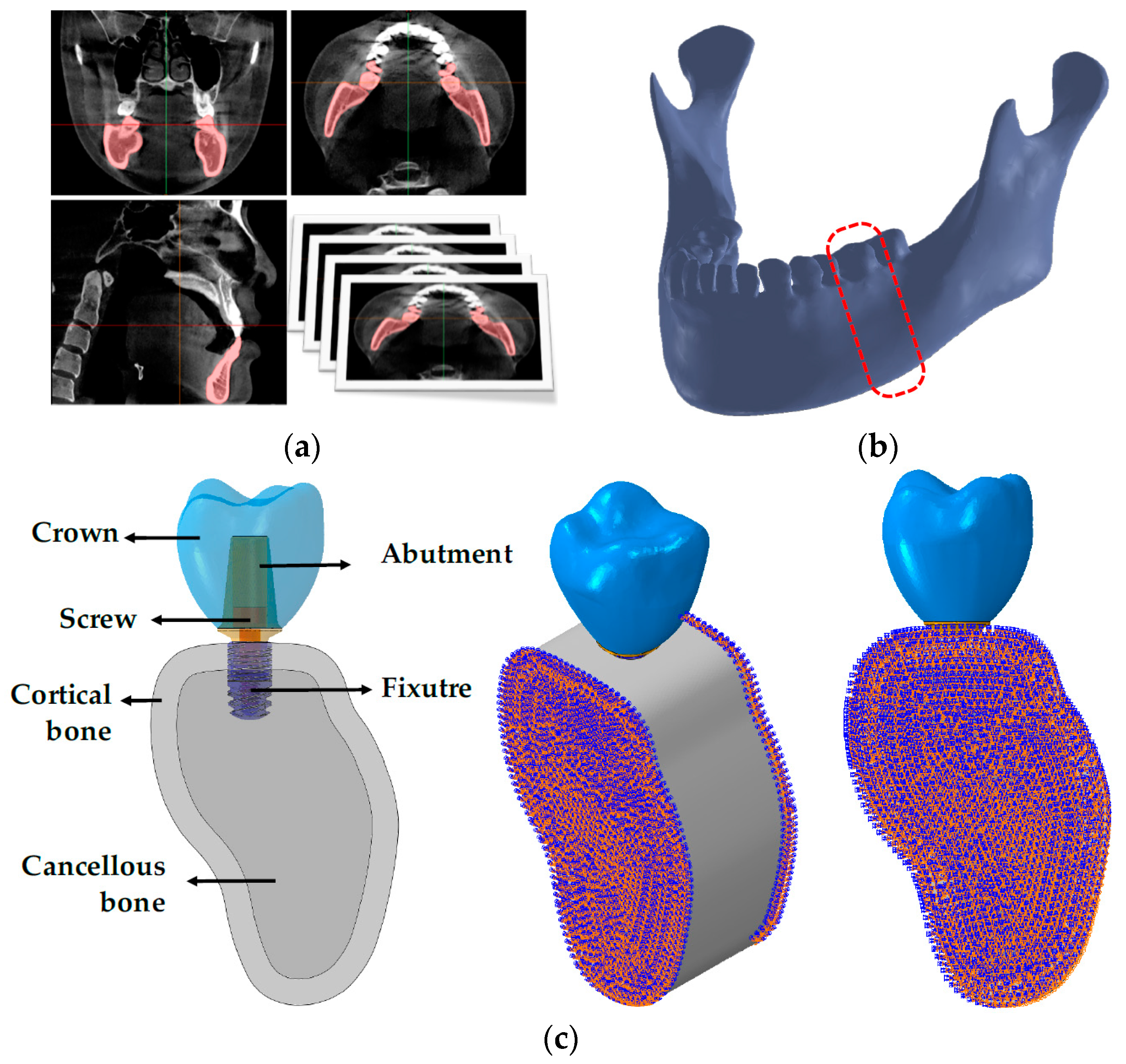
2. Materials and Methods
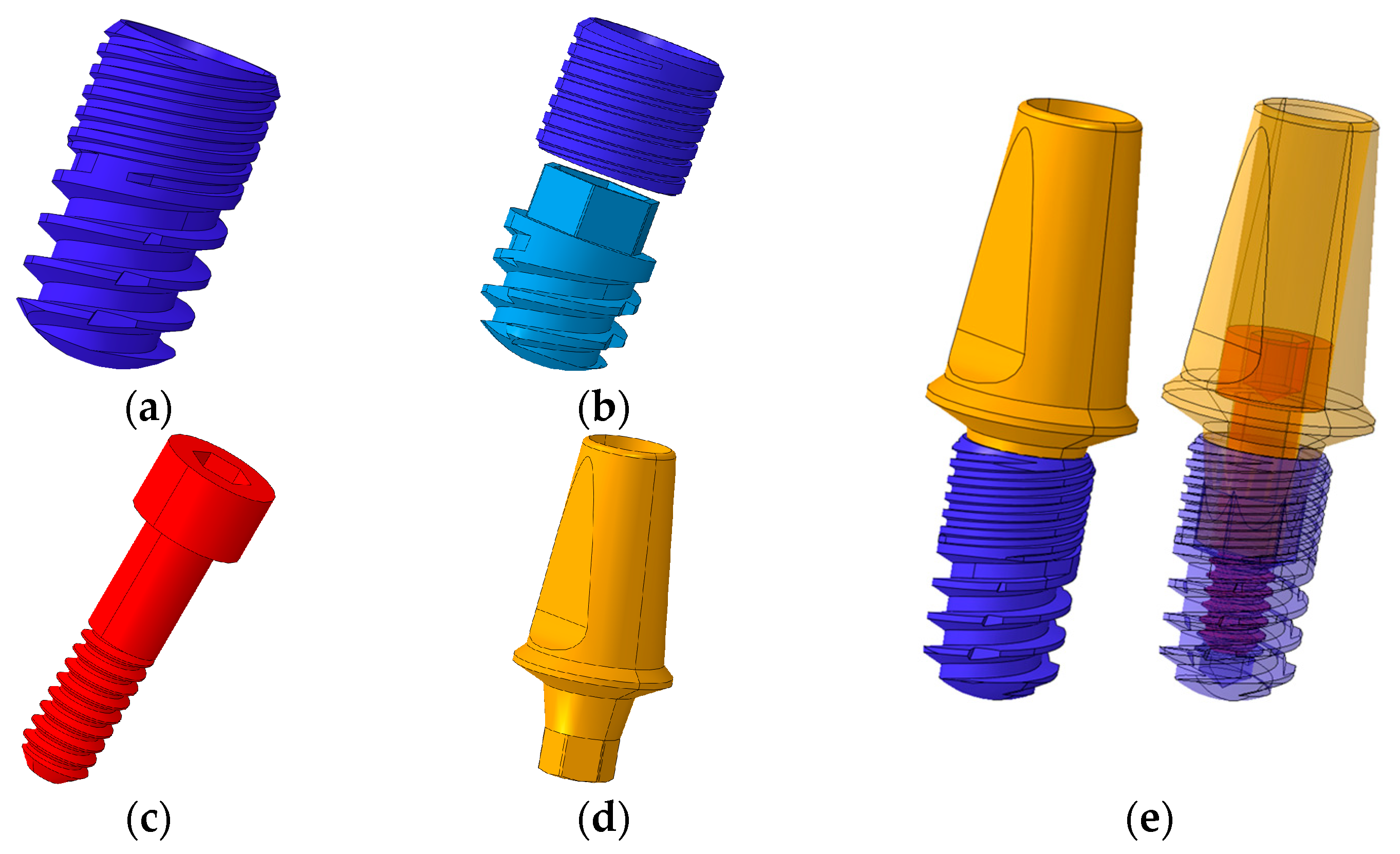
2.1. Designs and Dimensions of Conventional and Separable Fixtures
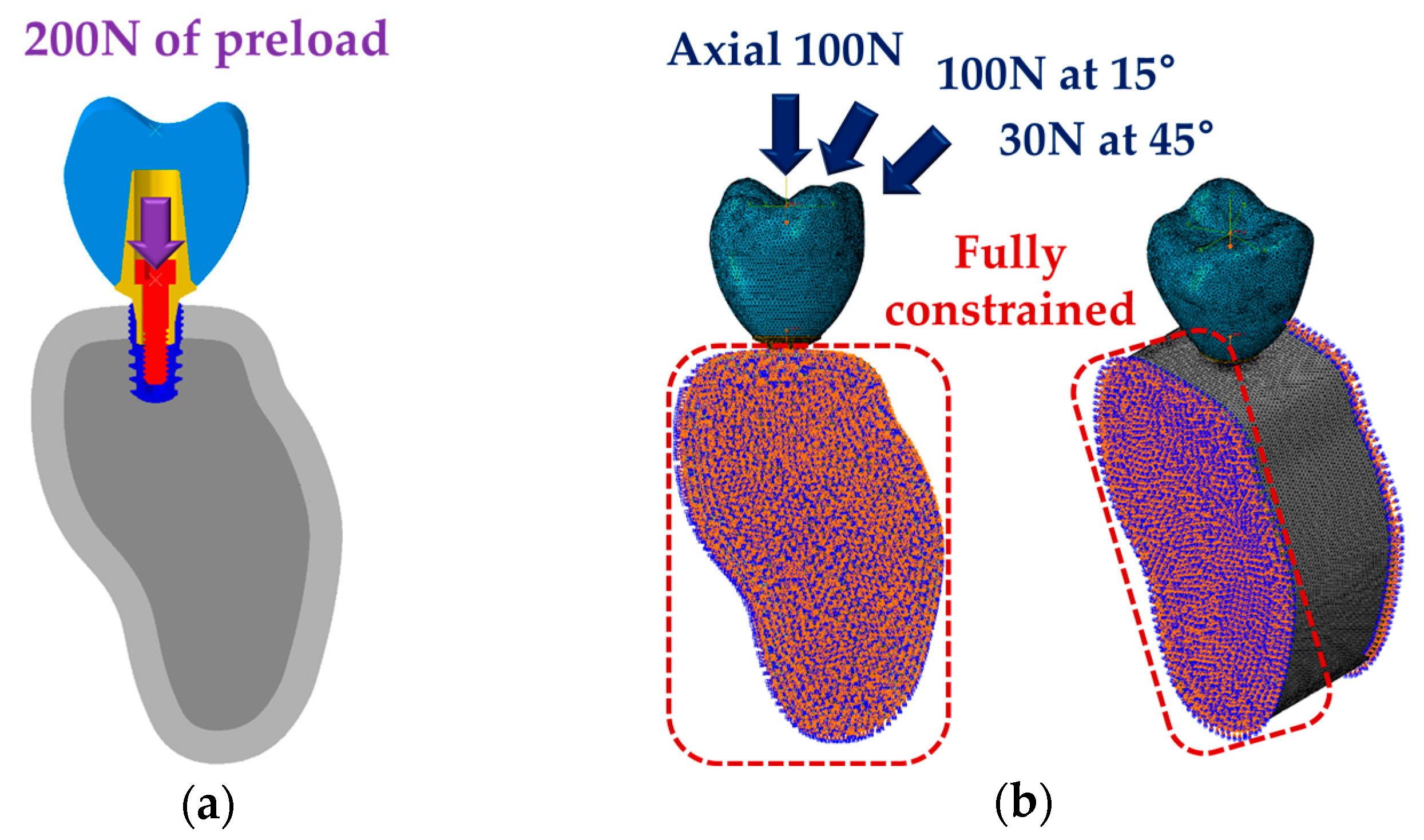
2.2. Finite Element Analysis (FEA)
2.3. Statistical Analysis
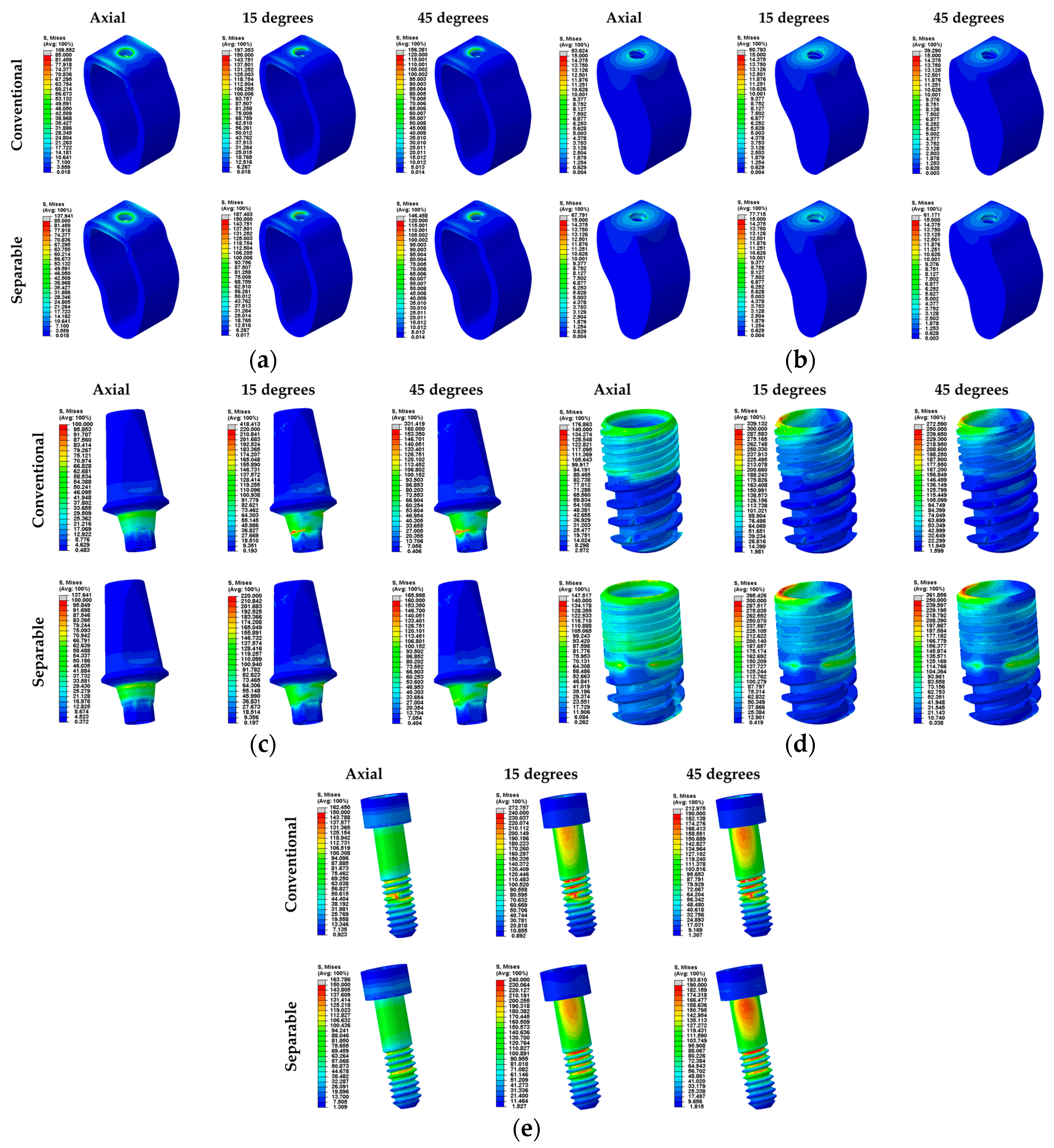
3. Results
4. Discussion
5. Conclusions
Author Contributions
Funding
Conflicts of Interest
References
- Calandriello, R.; Tomatis, M. Immediate occlusal loading of single lower molars using brånemark system® wide platform tiunite™ implants: A 5-year follow-up report of a prospective clinical multicenter study. Clin. Implant Dent. Relat. Res. 2009, 13, 311–318. [Google Scholar] [CrossRef] [PubMed]
- Hattingh, A.; Hommez, G.; De Bruyn, H.; Huyghe, M.; Vandeweghe, S. A prospective study on ultra-wide diameter dental implants for immediate molar replacement. Clin. Implant Dent. Relat. Res. 2018, 20, 1009–1015. [Google Scholar] [CrossRef] [PubMed]
- Bernardi, S.; Gatto, R.; Severino, M.; Botticelli, G.; Caruso, S.; Rastelli, C.; Lupi, E.; Roias, A.Q.; Iacomino, E.; Falisi, G. Short Versus Longer Implants in Mandibular Alveolar Ridge Augmented Using Osteogenic Distraction: One-Year Follow-up of a Randomized Split-Mouth Trial. J. Oral Implantol. 2018, 44, 184–191. [Google Scholar] [CrossRef] [PubMed]
- Gallucci, G.O.; Doughtie, C.B.; Hwang, J.W.; Fiorellini, J.P.; Weber, H.P. Five-year results of fixed implant-supported rehabilitations with distal cantilevers for the edentulous mandible. Clin. Oral Implants Res. 2009, 20, 601–607. [Google Scholar] [CrossRef] [PubMed]
- Lambert, F.E.; Weber, H.P.; Susarla, S.M.; Belser, U.C.; Gallucci, G.O. Descriptive analysis of implant and prosthodontic survival rates with fixed implant-supported rehabilitations in the edentulous maxilla. J. Periodontol. 2009, 80, 1220–1230. [Google Scholar] [CrossRef] [PubMed]
- Pjetursson, B.E.; Tan, K.; Lang, N.P.; Brägger, U.; Egger, M.; Zwahlen, M. A systematic review of the survival and complication rates of fixed partial dentures (FPDs) after an observation period of at least 5 years: I. Implant-supported FPDs. Clin. Oral Implants Res. 2004, 15, 625–642. [Google Scholar] [CrossRef] [PubMed]
- Lang, N.P.; Pjetursson, B.E.; Tan, K.; Brägger, U.; Egger, M.; Zwahlen, M. A systematic review of the survival and complication rates of fixed partial dentures (FPDs) after an observation period of at least 5 years: II. Combined tooth–implant-supported FPDs. Clin. Oral Implants Res. 2004, 15, 643–653. [Google Scholar] [CrossRef] [PubMed]
- Reyhanian, A.; Parker, S.; Moshonov, J.; Fuhrman, N. The use of Er: YAG in laser-assisted broken abutment screw treatment. Case Rep. Er YAG Lasers 2000, 3, 6–11. [Google Scholar]
- Adell, R.; Eriksson, B.; Lekholm, U.; Branemark, P.I.; Jemt, T.A. long-term follow-up study of osseointegrated implants in the treatment of totally edentulous jaws. Int. J. Oral Maxillofac. Implants 1990, 5, 347–358. [Google Scholar] [PubMed]
- Mahato, N.; Wu, X.; Wang, L. Management of peri-implantitis: A systematic review, 2010–2015. Springerplus 2016, 5, 105. [Google Scholar] [CrossRef]
- Scarano, A.; Quaranta, M.; Traini, T.; Piattelli, M.; Piattelli, A. SEM and Fractography analysis of screw thread loosening in dental implants. Int. J. Immunopathol. Pharmacol. 2007, 20, 19–22. [Google Scholar] [CrossRef] [PubMed]
- Satterthwaite, J.; Rickman, L. Retrieval of a fractured abutment screw thread from an implant: A case report. Br. Dent. J. 2008, 204, 177–180. [Google Scholar] [CrossRef] [PubMed]
- Froum, S.J.; Rosen, P.S. A proposed classification for peri-implantitis. Int. J. Periodontics Restor. Dent. 2012, 32, 533–540. [Google Scholar]
- Heitz-Mayfield, L.J.; Mombelli, A. The therapy of peri-implantitis: A systematic review. Int. J. Oral Maxillofac. Implants 2014, 29, 325–345. [Google Scholar] [CrossRef]
- Klinge, B.; Gustafsson, A.; Berglundh, T. A systematic review of the effect of anti-infective therapy in the treatment of peri-implantitis. J. Clin. Periodontol. 2002, 29, 213–225. [Google Scholar] [CrossRef] [PubMed]
- Renvert, S.; Roos-Jansaker, A.M.; Claffey, N. Non-surgical treatment of peri-implant mucositis and peri-implantitis:A literature review. J. Clin. Periodontal. 2008, 35, 305–315. [Google Scholar] [CrossRef]
- Bernardi, S.; Bianchi, S.; Botticelli, G.; Rastelli, E.; Tomei, A.R.; Palmerini, M.G.; Continenze, M.A.; Macchiarelli, G. Scanning electron microscopy and microbiological approaches for the evaluation of salivary microorganisms behaviour on anatase titanium surfaces: In vitro study. Morphologie 2018, 102, 1–6. [Google Scholar] [CrossRef] [PubMed]
- Smeets, R.; Stadlinger, B.; Schwarz, F.; Beck-Broichsitter, B.; Jung, O.; Precht, C.; Kloss, E.; Gröbe, A.; Heiland, M.; Ebker, T. Impact of dental implant surface modifications on osseointegration. BioMed Res. Int. 2016, 2016, 6285620. [Google Scholar] [CrossRef] [PubMed]
- Alani, A.; Bishop, K. Peri-implantitis. Part 3: Current modes of management. Br. Dent. J. 2014, 217, 345–349. [Google Scholar] [CrossRef] [PubMed]
- Wohlfahrt, J.C.; Aass, A.M.; Ronold, H.J.; Lyngstadaas, S.P. Micro CT and human histological analysis of a peri-implant osseous defect grafted with porous titanium granules: A case report. Int. J. Oral Maxillofac. Implants 2011, 26, e9–e14. [Google Scholar]
- Singh, P. Understanding peri-implantitis: A strategic review. J. Oral Implantol. 2011, 37, 622–626. [Google Scholar] [CrossRef] [PubMed]
- Heasman, P.; Esmail, Z.; Barclay, C. Peri-Implant Diseases. Dent. Update 2010, 37, 511–516. [Google Scholar] [CrossRef] [PubMed]
- Bassi, F.; Poli, P.P. Surgical treatment of peri-implantitis: A 17-year follow-up clinical case report. Case Rep. Dent. 2015, 2015, 574676. [Google Scholar] [CrossRef] [PubMed]
- Cappiello, M.; Luongo, R.; Di Iorio, D.; Bugea, C.; Cocchetto, R.; Celletti, R. Evaluation of peri-implant bone loss around platform-switched implants. Int. J. Periodontics Restor. Dent. 2008, 28, 20–33. [Google Scholar]
- Brizuela-Velasco, A.; Pérez-Pevida, E.; Jiménez-Garrudo, A.; Gil-Mur, F.J.; Manero, J.M.; Punset-Fuste, M.; Chávarri-Prado, D.; Diéguez-Pereira, M.; Monticelli, F. Mechanical characterisation and biomechanical and biological behaviours of Ti-Zr Binary-Alloy dental implants. BioMed Res. Int. 2017, 2017, 2785863. [Google Scholar] [CrossRef] [PubMed]
- Foley, J.; Dodson, J.; Schmidt, M.; Gillespie, P.; Besonia, Y. High-bandwidth Measurement and Validation of Bar and Plate Dynamics; Air Force Research Lab, Munitions Directorate: Eglin AFB, FL, USA, 2008. [Google Scholar]
- Zhang, G.; Yuan, H.; Chen, X.; Wang, W.; Chen, J.; Liang, J.; Zhang, P. A three-dimensional finite element study on the biomechanical simulation of various structured dental implants and their surrounding bone tissues. Int. J. Dent. 2016, 2016, 4867402. [Google Scholar] [CrossRef] [PubMed]
- Ao, J.; Li, T.; Liu, Y.; Ding, Y.; Wu, G.; Hu, K.; Kong, L. Optimal design of thread height and width on an immediately loaded cylinder implant: A finite element analysis. Comput. Biol. Med. 2010, 40, 681–686. [Google Scholar] [CrossRef] [PubMed]
- Chun, H.J.; Cheong, S.Y.; Han, J.H.; Heo, S.J.; Chung, J.P.; Rhyu, I.C.; Choi, Y.C.; Baik, H.K.; Ku, Y.; Kim, M.H. Evaluation of design parameters of osseointegrated dental implants using finite element analysis. J. Oral Rehabil. 2002, 29, 565–574. [Google Scholar] [CrossRef]
- Weinstein, A.M.; Klawitter, J.J.; Anand, S.C.; Schuessler, R. Stress analysis of porous rooted dental implants. J. Dent. Res. 1976, 55, 772–777. [Google Scholar] [CrossRef]
- Yang, J.; Xiang, H.J. A three-dimensional finite element study on the biomechanical behavior of an FGBM dental implant in surrounding bone. J. Biomech. 2007, 40, 2377–2385. [Google Scholar] [CrossRef]
- Throckmorton, G.S.; Buschang, P.H.; Ellis, E. III. Improvement of maximum occlusal forces after orthognathic surgery. J. Oral Maxillofac. Surg. 1996, 54, 1080–1086. [Google Scholar] [CrossRef]
- Miyamoto, I.; Tsuboi, Y.; Wada, E.; Suwa, H.; Iizuka, T. Influence of cortical bone thickness and implant length on implant stability at the time of surgery—Clinical, prospective, biomechanical, and imaging study. Bone 2005, 37, 776–780. [Google Scholar] [CrossRef]
- Ha, S.R. Biomechanical three-dimensional finite element analysis of monolithic zirconia crown with different cement type. J. Adv. Prosthodont. 2015, 7, 475–483. [Google Scholar] [CrossRef] [PubMed]
- Tribst, J.P.M.; Dal Piva, A.M.D.O.; Rodrigues, V.A.; Borges, A.L.S.; Nishioka, R.S. Stress and strain distributions on short implants with two different prosthetic connections—An in vitro and in silico analysis. Braz. Dent. Sci. 2017, 20, 101–109. [Google Scholar] [CrossRef]
- Mellal, A.; Wiskott, H.W.A.; Botsis, J.; Scherrer, S.S.; Belser, U.C. Stimulating effect of implant loading on surrounding bone: Comparison of three numerical models and validation by in vivo data. Clin. Oral Implants Res. 2004, 15, 239–248. [Google Scholar] [CrossRef] [PubMed]
- Barbier, L.; Sloten, J.V.; Krzesinski, G.; Van Der Perre, E.S.G. Finite element analysis of non-axial versus axial loading of oral implants in the mandible of the dog. J. Oral Rehabil. 1998, 25, 847–858. [Google Scholar] [CrossRef] [PubMed]
- Lu, Y.J.; Chang, S.H.; Ye, J.T.; Ye, Y.S.; Yu, Y.S. Finite Element Analysis of Bone Stress around Micro-Implants of Different Diameters and Lengths with Application of a Single or Composite Torque Force. PLoS ONE 2015, 10, e0144744. [Google Scholar] [CrossRef] [PubMed]
- Elias, C.N.; Lima, J.H.C.; Valiev, R.; Meyers, M.A. Biomedical applications of titanium and its alloys. JOM 2008, 60, 46–49. [Google Scholar] [CrossRef]
- Geng, J.P.; Tan, K.B.; Liu, G.R. Application of finite element analysis in implant dentistry: A review of the literature. J. Prosthet. Dent. 2001, 85, 585–598. [Google Scholar] [CrossRef]


| Components | Young’s Modulus (MPa) | Poisson’s Ratio |
|---|---|---|
| Crown (Zirconia) [34] | 205,000 | 0.19 |
| Abutment (Ti-grade 5) [26] | 114,000 | 0.33 |
| Fixture (Ti-grade 4) [25] | 105,000 | 0.34 |
| Abutment screw (Ti-grade 5) [26] | 114,000 | 0.33 |
| Cortical bone [27] | 13,000 | 0.30 |
| Cancellous bone [27] | 690 | 0.30 |
| Elements | Nodes | Mesh Size (mm) | ||||
|---|---|---|---|---|---|---|
| Conventional Fixture | Separable Fixture | Conventional Fixture | Separable Fixture | Maximum | Minimum | |
| Crown | 121,740 | 25,678 | 0.30 | 0.15 | ||
| Abutment | 88,637 | 21,139 | 0.15 | 0.05 | ||
| Fixture | 125,966 | 48,692 (up) 104,432 (down) | 24,396 | 12,300 (up) 23,594 (down) | 0.15 | 0.05 |
| Abutment screw | 60,588 | 13,836 | 0.15 | 0.03 | ||
| Cortical bone | 287,389 | 295,533 | 62,917 | 64,492 | 1.00 | 0.15 |
| Cancellous bone | 275,822 | 273,597 | 57,108 | 56,765 | 1.00 | 0.15 |
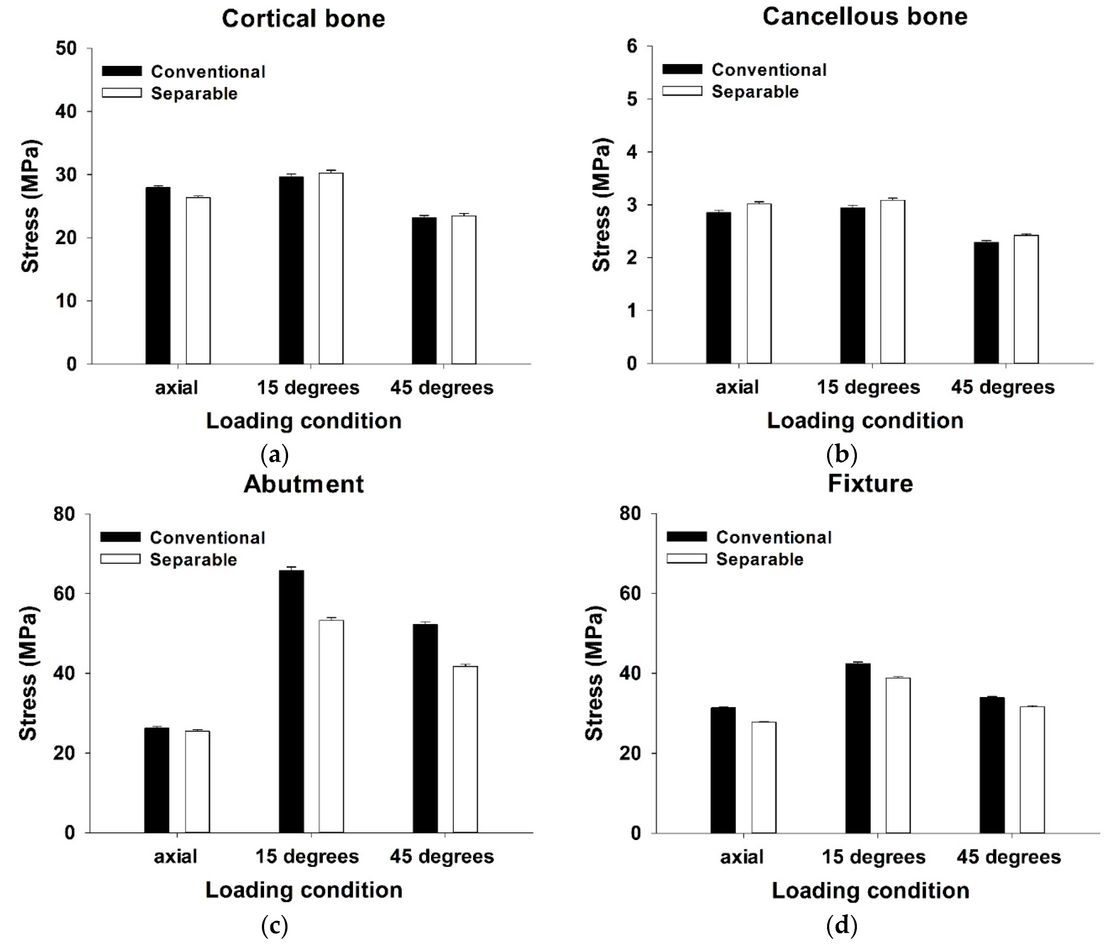
| Direction | Maximum Equivalent Stress (MPa) | |||||
|---|---|---|---|---|---|---|
| Conventional Fixture | Number of Node | Separable Fixture | Number of Node | p-Value | ||
| Cortical bone | 100N (Axial) | 27.97 ± 0.28 | 3881 | 26.38 ± 0.26 | 3993 | <0.001 ** |
| 100N (15°) | 28.88 ± 0.46 | 29.73 ± 0.47 | 0.368 | |||
| 100N (45°) | 22.89 ± 0.37 | 23.32 ± 0.37 | 0.535 | |||
| Cancellous bone | 100N (Axial) | 2.85 ± 0.05 | 4745 | 3.02 ± 0.04 | 5696 | 0.008 ** |
| 100N (15°) | 2.94 ± 0.05 | 3.09 ± 0.04 | 0.019 * | |||
| 100N (45°) | 2.29 ± 0.04 | 2.42 ± 0.03 | 0.006 ** | |||
| Abutment outer surface | 100N (Axial) | 26.32 ± 0.33 | 3569 | 25.49 ± 0.40 | 3569 | 0.108 |
| 100N (15°) | 65.81 ± 0.91 | 53.29 ± 0.67 | <0.001 ** | |||
| 100N (45°) | 52.23 ± 0.72 | 41.74 ± 0.53 | <0.001 ** | |||
| Fixture inner surface | 100N (Axial) | 31.34 ± 0.18 | 7109 | 27.79 ± 0.18 | 7311 | <0.001 ** |
| 100N (15°) | 42.46 ± 0.36 | 38.84 ± 0.32 | <0.001 ** | |||
| 100N (45°) | 33.83 ± 0.29 | 31.57 ± 0.26 | <0.001 ** | |||
| PVMS (MPa) | ||||||
|---|---|---|---|---|---|---|
| Abutment | Fixture | Abutment Screw | ||||
| Conventional Fixture | Separable Fixture | Conventional Fixture | Separable Fixture | Conventional Fixture | Separable Fixture | |
| 100N (Axial) | 95.853 | 137.64 | 176.86 | 147.52 | 162.45 | 163.79 |
| 100N (15°) | 418.41 | 218.87 | 339.13 | 395.43 | 272.76 | 239.09 |
| 100N (45°) | 339.13 | 165.99 | 272.59 | 361.86 | 212.98 | 193.61 |
© 2019 by the authors. Licensee MDPI, Basel, Switzerland. This article is an open access article distributed under the terms and conditions of the Creative Commons Attribution (CC BY) license (http://creativecommons.org/licenses/by/4.0/).
Share and Cite
Kim, W.H.; Song, E.S.; Ju, K.W.; Lee, J.-H.; Kim, M.Y.; Lim, D.; Kim, B. Finite Element Analysis of Novel Separable Fixture for Easy Retrievement in Case with Peri-Implantitis. Materials 2019, 12, 235. https://doi.org/10.3390/ma12020235
Kim WH, Song ES, Ju KW, Lee J-H, Kim MY, Lim D, Kim B. Finite Element Analysis of Novel Separable Fixture for Easy Retrievement in Case with Peri-Implantitis. Materials. 2019; 12(2):235. https://doi.org/10.3390/ma12020235
Chicago/Turabian StyleKim, Won Hyeon, Eun Sung Song, Kyung Won Ju, Jong-Ho Lee, Man Yong Kim, Dohyung Lim, and Bongju Kim. 2019. "Finite Element Analysis of Novel Separable Fixture for Easy Retrievement in Case with Peri-Implantitis" Materials 12, no. 2: 235. https://doi.org/10.3390/ma12020235
APA StyleKim, W. H., Song, E. S., Ju, K. W., Lee, J.-H., Kim, M. Y., Lim, D., & Kim, B. (2019). Finite Element Analysis of Novel Separable Fixture for Easy Retrievement in Case with Peri-Implantitis. Materials, 12(2), 235. https://doi.org/10.3390/ma12020235