Thermal Effects in the Ablation of Bovine Cortical Bone with Pulsed Laser Sources

 ,
, 
Abstract
1. Introduction
2. Materials and Methods
3. Results
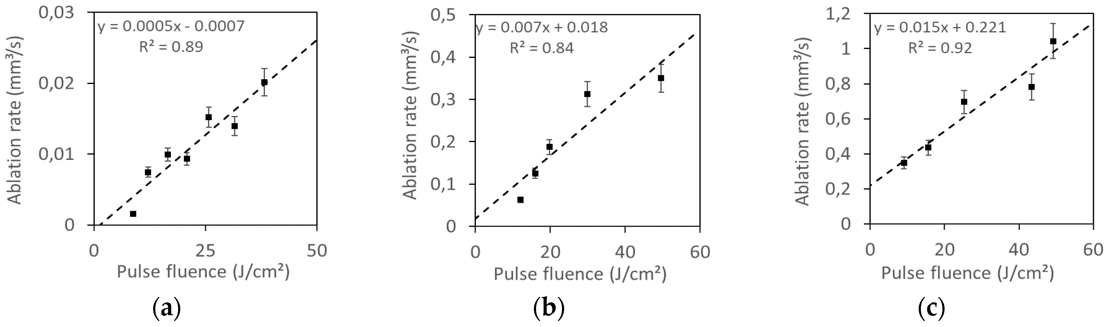
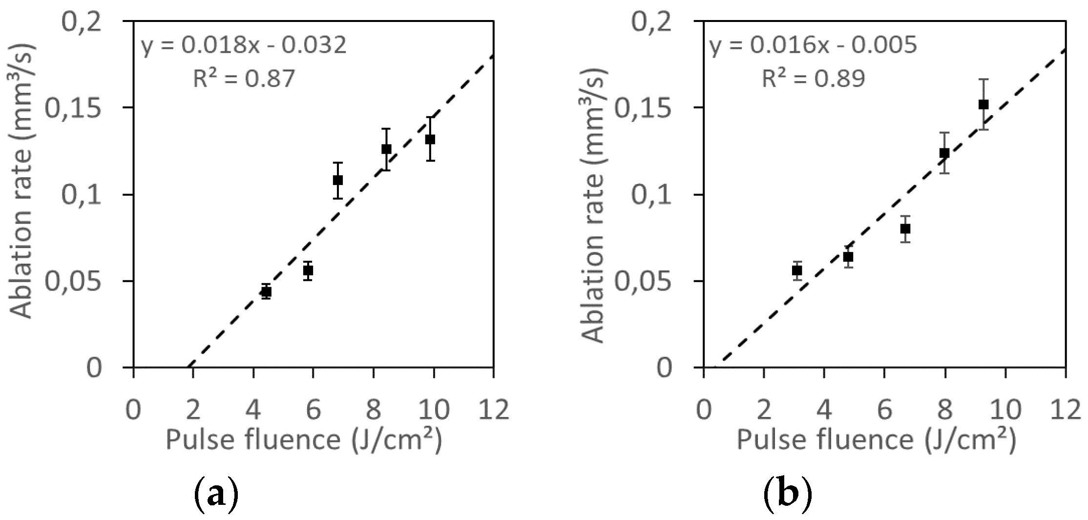
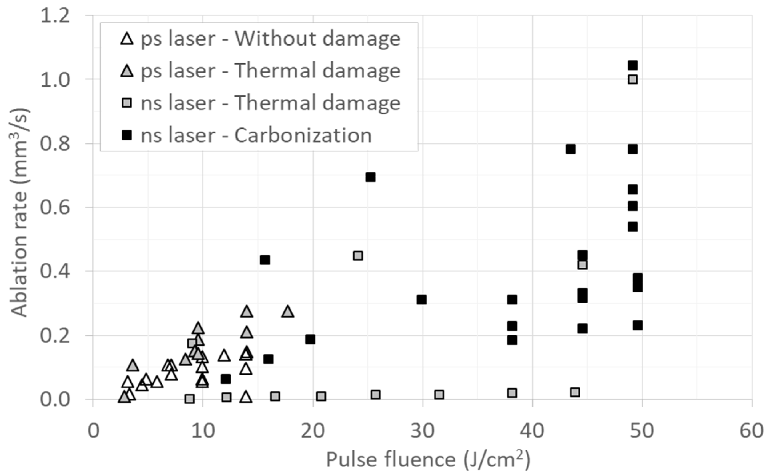
3.1. Ablation Rate
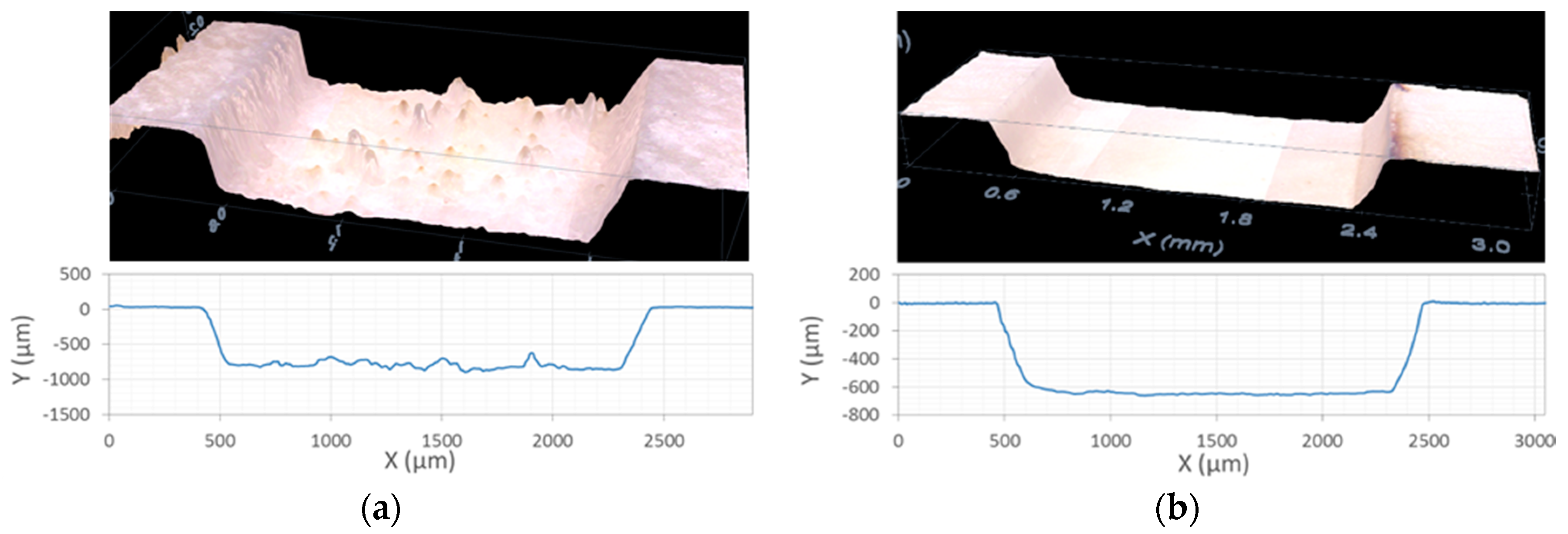
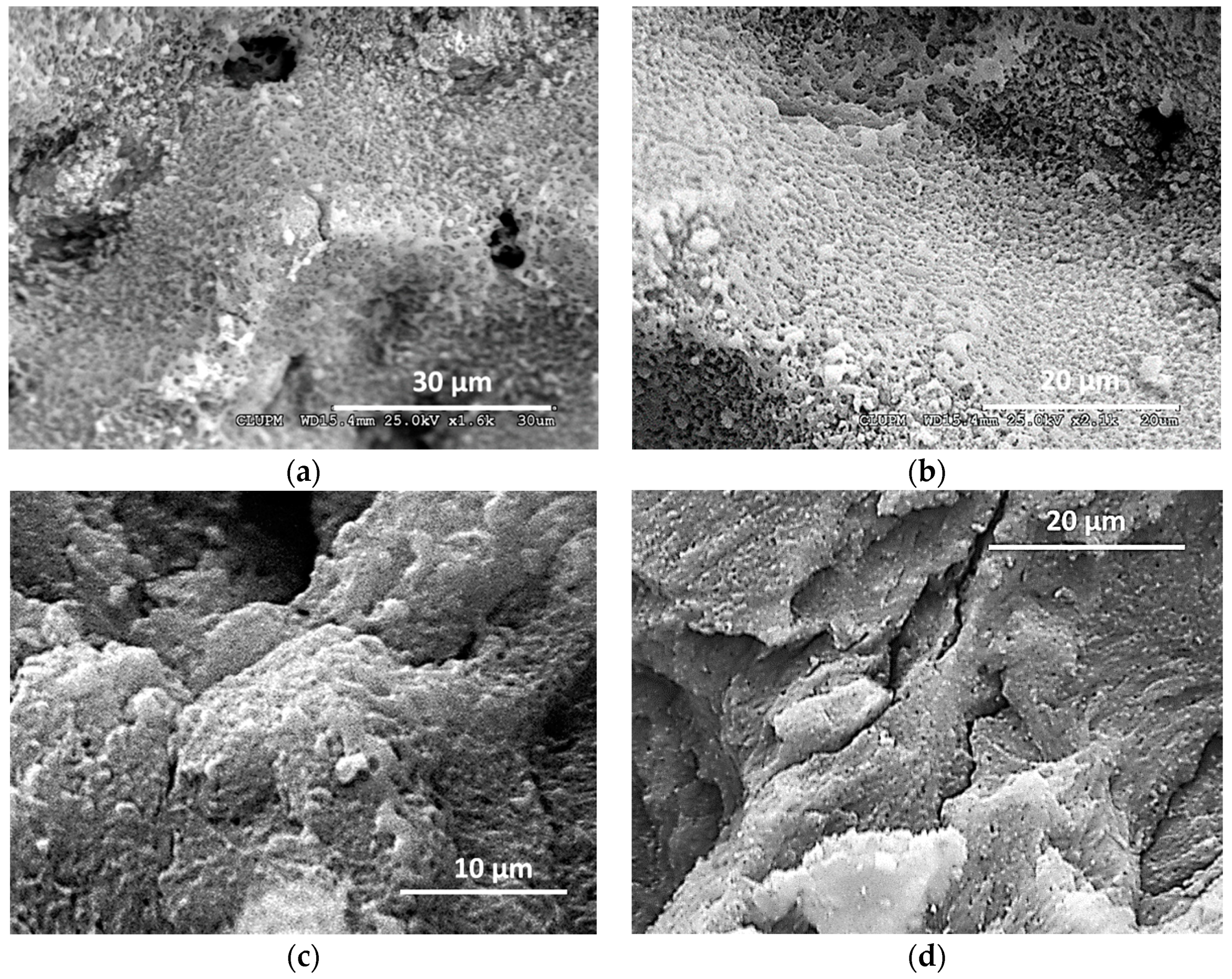
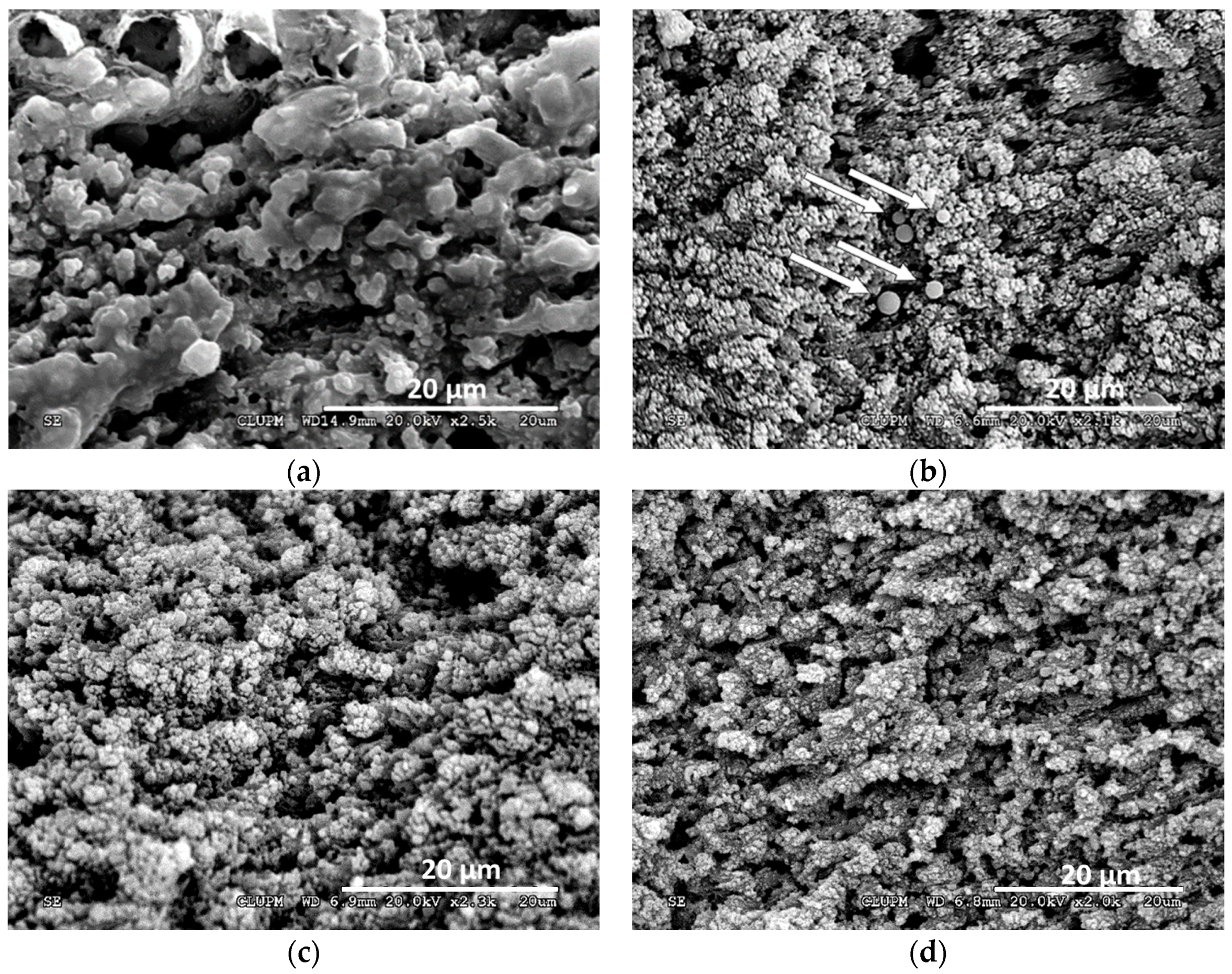
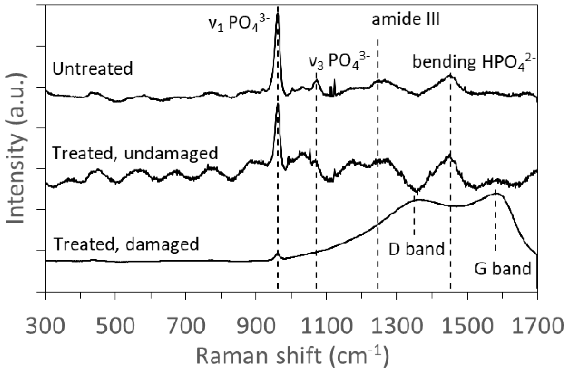
3.2. Morphology Characterization and Thermal Damage
3.2.1. UV NS Laser
3.2.2. IR PS Laser
4. Discussion
Author Contributions
Funding
Conflicts of Interest
References
- Vv.Aa. Applied Laser Medicine; Berlien, H.-P., Müller, G.J., Eds.; Springer: Berlin/Heidelberg, Germany, 2003; ISBN 9783642189791. [Google Scholar]
- Buchelt, M.; Kutschera, H.-P.; Katterschafka, T.; Kiss, H.; Lang, S.; Beer, R.; Losert, U. Er:YAG and Ho:YAG Laser Osteotomy: The Effect of Laser Ablation on Bone Healing. Lasers Surg. Med. 1994, 15, 373–381. [Google Scholar] [CrossRef] [PubMed]
- Ivanenko, M.M.; Fahimi-Weber, S.; Mitra, T.; Wierich, W.; Hering, P. Bone tissue ablation with sub-μs pulses of a Q-switch CO2 laser: Histological examination of thermal side effects. Lasers Med. Sci. 2002, 17, 258–264. [Google Scholar] [CrossRef] [PubMed]
- Kuttenberger, J.J.; Waibel, A.; Stübinger, S.; Werner, M.; Klasing, M.; Ivanenko, M.; Hering, P.; Von Rechenberg, B.; Sader, R.; Zeilhofer, H.F. Bone healing of the sheep tibia shaft after carbon dioxide laser osteotomy: Histological results. Lasers Med. Sci. 2010, 25, 239–249. [Google Scholar] [CrossRef] [PubMed]
- Werner, M.; Klasing, M.; Ivanenko, M.; Harbecke, D.; Steigerwald, H.; Hering, P. CO2 laser free-form processing of hard tissue. In Proceedings of the Therapeutic Laser Applications and Laser-Tissue Interactions III, Munich, Germany, 17 June 2007. [Google Scholar]
- Stock, K.; Diebolder, R.; Hausladen, F.; Hibst, R. Efficient bone cutting with the novel diode pumped Er: YAG laser system: in vitro investigation and optimization of the treatment parameters. In Proceedings of the SPIE-OSA Biomedical Optics, San Francisco, CA, USA, 4 March 2014. [Google Scholar]
- Baek, K.; Deibel, W.; Marinov, D.; Griessen, M.; Dard, M.; Dmd, P.; Bruno, A.; Zeilhofer, H. A Comparative Investigation of Bone Surface After Cutting with Mechanical Tools and Er: YAG Laser. Lasers Surg. Med. 2015, 47, 426–432. [Google Scholar] [CrossRef] [PubMed]
- Tulea, C.; Noll, R. Laser cutting of bone tissue under bulk water with a pulsed ps-laser at 532 nm. J. Biomed. Opt. 2015, 20, 105107. [Google Scholar] [CrossRef] [PubMed]
- Ivanenko, M.; Werner, M.; Afilal, S.; Klasing, M.; Hering, P. Ablation of hard bone tissue with pulsed CO2 lasers. Med. Laser Appl. 2005, 20, 13–23. [Google Scholar] [CrossRef]
- Plötz, C.; Schelle, F.; Bourauel, C.; Frentzen, M.; Meister, J. Ablation of porcine bone tissue with an ultrashort pulsed laser (USPL) system. Lasers Med. Sci. 2014, 30, 977–983. [Google Scholar] [CrossRef]
- Liu, Y.; Niemz, M.; Ablation, B. Ablation of femural bone with femtosecond laser pulses—A feasibility study. Lasers Med. Sci. 2007, 22, 171–174. [Google Scholar] [CrossRef]
- Cangueiro, L.T.; Vilar, R. Applied Surface Science Influence of the pulse frequency and water cooling on the femtosecond laser ablation of bovine cortical bone. Appl. Surf. Sci. 2013, 283, 1012–1017. [Google Scholar] [CrossRef]
- Cangueiro, L.T.; Quang, T.L.; Vilar, R. Laser surface modification of biological hard tissues. In Laser Surface Modification of Biomaterials; Vilar, R., Ed.; Elsevier Ltd.: Amsterdam, The Netherlands, 2016; ISBN 9780081008836. [Google Scholar]
- Geraldo-Martins, V.R.; Tanji, E.Y.; Wetter, N.U.; Nogueira, R.D.; Eduardo, C.P. Intrapulpal Temperature during Preparation with the Er:YAG Laser: An in Vitro Study. Photomed. Laser Surg. 2005, 23, 182–186. [Google Scholar] [CrossRef]
- Delmé, K.I.M.; Cardoso, M.V.; Mine, A.; De Moor, R.J.G.; Meerbeek, B. Van Transmission Electron Microscopic Examination of the Interface Between a Resin-Modified Glass-Ionomer and Er:YAG Laser-Irradiated Dentin. Photomed. Laser Surg. 2009, 27, 317–323. [Google Scholar] [CrossRef] [PubMed]
- Cangueiro, L.T.; Vilar, R.; Botelho do Rego, A.M.; Muralha, V.S.F. Femtosecond laser ablation of bovine cortical bone. J. Biomed. Opt. 2012, 17, 125005. [Google Scholar] [CrossRef] [PubMed]
- Emigh, B.; Hsu, E.M.; Crawford, T.H.R.; Haugen, H.K.; Wohl, G.R.; Hayward, J.E. Porcine cortical bone ablation by ultrashort pulsed laser irradiation. J. Biomed. Opt. 2012, 17, 028001. [Google Scholar] [CrossRef] [PubMed]
- Murugan, R.; Ramakrishna, S. Development of nanocomposites for bone grafting. Compos. Sci. Technol. 2005, 65, 2385–2406. [Google Scholar] [CrossRef]
- Sekar, S.K.V.; Mora, A.D.; Taroni, P.; Pifferi, A.; Bargigia, I.; Farina, A.; Ruggeri, A.; Tosi, A. Diffuse optical characterization of collagen absorption from 500 to 1700 nm. J. Biomed. Opt. 2017, 22, 015006. [Google Scholar] [CrossRef]
- Bona, A.; de Azevedo, C.S.; da Ana, P.A.; Brossi, S.; Maria, D. Laser Technology for Caries Removal. Contemp. Approach Dent. Caries 2012. [CrossRef]
- Ravichandran, R.; Islam, M.M.; Alarcon, E.I.; Samanta, A.; Wang, S.; Lundström, P.; Hilborn, J.; Griffith, M.; Phopase, J. Functionalised type-I collagen as a hydrogel building block for bio-orthogonal tissue engineering applications. J. Mater. Chem. B 2016, 4, 318–326. [Google Scholar] [CrossRef]
- Vogel, A.; Venugopalan, V. Mechanisms of Pulsed Laser Ablation of Biological Tissues. Chem. Rev. 2003, 103, 577–644. [Google Scholar] [CrossRef]
- Jowett, N.; Wo, W.; Wiseman, P.W.; Mlynarek, A.M.; Bo, A.; Knecht, R.; Miller, R.J.D. Bone Ablation without Thermal or Acoustic Mechanical Injury via a Novel Picosecond Infrared Laser (PIRL). Otolaryngol. Neck Surg. 2014, 150, 385–393. [Google Scholar] [CrossRef]
- Penel, G.; Delfosse, C.; Descamps, M.; Leroy, G. Composition of bone and apatitic biomaterials as revealed by intravital Raman microspectroscopy. Bone 2005, 36, 893–901. [Google Scholar] [CrossRef]
- Scheibe, H.-J.; Drescher, D.; Alers, P. Raman characterization of amorphous carbon films. Fresenius. J. Anal. Chem. 1995, 353, 695–697. [Google Scholar] [CrossRef]
- Hermann, J.; Benfarah, M.; Bruneau, S.; Axente, E.; Coustillier, G.; Itina, T.; Guillemoles, J.F.; Alloncle, P. Comparative investigation of solar cell thin film processing using nanosecond and femtosecond lasers. J. Phys. D Appl. Phys. 2006, 39, 453–460. [Google Scholar] [CrossRef]
- Schelle, F.; Polz, S.; Haloui, H.; Braun, A.; Dehn, C.; Frentzen, M.; Meister, J. Ultrashort pulsed laser (USPL) application in dentistry: basic investigations of ablation rates and thresholds on oral hard tissue and restorative materials. Lasers Med. Sci. 2014, 29, 1775–1783. [Google Scholar] [CrossRef] [PubMed]
- Turcotte, R.; Alt, C.; Mortensen, L.J.; Lin, C.P. Characterization of multiphoton microscopy in the bone marrow following intravital laser osteotomy. Biomed. Opt. Express 2014, 5, 3578–3588. [Google Scholar] [CrossRef] [PubMed]


| Laser Source | Frequency kHz | Speed mm/s | Fluence J/cm2 | Pitch µm | Cycles | Op % |
|---|---|---|---|---|---|---|
| PULSEO (355 nm, ns) | 2–100 | 50–7000 | 8.8–49.6 | 50–100 | 20–100 | 0–20 |
| Atlantic (1064 nm, ps) | 100–600 | 100–5000 | 2.8–17.7 | 10–20 | 20–60 | 0–98 |
| Laser source | Frequency kHz | Speed mm/s | Fluence J/cm2 | Pitch µm | Cycles | Ablation Rate mm3/s |
|---|---|---|---|---|---|---|
| PULSEO (355 nm, ns) | 60 | 4000 | 49.2 | 50 | 20 | 1.00 |
| 30 | 3000 | 24.1 | 50 | 50 | 0.45 | |
| 20 | 2000 | 44.6 | 50 | 50 | 0.42 | |
| 60 | 4000 | 9.0 | 50 | 40 | 0.17 | |
| Atlantic (1064 nm, ps) | 100 | 500 | 13.9 | 10 | 20 | 0.15 |
| 100 | 500 | 11.9 | 10 | 20 | 0.14 | |
| 100 | 500 | 9.9 | 10 | 20 | 0.13 | |
| 400 | 5000 | 7.1 | 10 | 20 | 0.11 |
© 2019 by the authors. Licensee MDPI, Basel, Switzerland. This article is an open access article distributed under the terms and conditions of the Creative Commons Attribution (CC BY) license (http://creativecommons.org/licenses/by/4.0/).
Share and Cite
Canteli, D.; Muñoz-García, C.; Morales, M.; Márquez, A.; Lauzurica, S.; Arregui, J.; Lazkoz, A.; Molpeceres, C. Thermal Effects in the Ablation of Bovine Cortical Bone with Pulsed Laser Sources. Materials 2019, 12, 2916. https://doi.org/10.3390/ma12182916
Canteli D, Muñoz-García C, Morales M, Márquez A, Lauzurica S, Arregui J, Lazkoz A, Molpeceres C. Thermal Effects in the Ablation of Bovine Cortical Bone with Pulsed Laser Sources. Materials. 2019; 12(18):2916. https://doi.org/10.3390/ma12182916
Chicago/Turabian StyleCanteli, David, Cristina Muñoz-García, Miguel Morales, Andrés Márquez, Sara Lauzurica, Juan Arregui, Aritz Lazkoz, and Carlos Molpeceres. 2019. "Thermal Effects in the Ablation of Bovine Cortical Bone with Pulsed Laser Sources" Materials 12, no. 18: 2916. https://doi.org/10.3390/ma12182916
APA StyleCanteli, D., Muñoz-García, C., Morales, M., Márquez, A., Lauzurica, S., Arregui, J., Lazkoz, A., & Molpeceres, C. (2019). Thermal Effects in the Ablation of Bovine Cortical Bone with Pulsed Laser Sources. Materials, 12(18), 2916. https://doi.org/10.3390/ma12182916