Article

Stress Concentration Induced by the Crystal Orientation in the Transient-Liquid-Phase Bonded Joint of Single-Crystalline Ni3Al

1
Guangdong Provincial Key Laboratory of Advanced Welding Technology, Guangdong Welding Institute (China-Ukraine E.O. Paton Institute of Welding), Guangzhou 541630, China
2
Key Laboratory of Guangxi Manufacturing System and Advanced Manufacturing Technology, Guilin University of Electronic Technology, Guilin 541004, China
*
Authors to whom correspondence should be addressed.
Materials 2019, 12(17), 2765; https://doi.org/10.3390/ma12172765
Submission received: 8 August 2019 / Revised: 22 August 2019 / Accepted: 26 August 2019 / Published: 28 August 2019
(This article belongs to the Special Issue Welding, Joining and Coating of Metallic Materials)

Abstract

:
Single-crystalline Ni3Al-based superalloys have been widely used in aviation, aerospace, and military fields because of their excellent mechanical properties, especially at extremely high temperatures. Usually, single-crystalline Ni3Al-based superalloys are welded together by a Ni3Al-based polycrystalline alloy via transient liquid phase (TLP) bonding. In this study, the elastic constants of single-crystalline Ni3Al were calculated via density functional theory (DFT) and the elastic modulus, shear modulus, and Poisson’s ratio of the polycrystalline Ni3Al were evaluated by the Voigt–Reuss approximation method. The results are in good agreement with previously reported experimental values. Based on the calculated mechanical properties of single-crystalline and polycrystalline Ni3Al, three-dimensional finite element analysis (FEA) was used to characterize the mechanical behavior of the TLP bonded joint of single-crystalline Ni3Al. The simulation results reveal obvious stress concentration in the joint because of the different states of crystal orientation between single crystals and polycrystals, which may induce failure in the polycrystalline Ni3Al and weaken the mechanical strength of the TLP bonded joint. Furthermore, results also show that the decrease in the elastic modulus of the intermediate layer (i.e., polycrystalline Ni3Al) can relieve the stress concentration and improve the mechanical strength in the TLP bonded joint.

1. Introduction

Owing to their extremely high tensile strength, toughness, endurance strength, fatigue strength, corrosion resistance, and oxidation resistance at high temperatures (such as ≥980 °C), nickel(Ni)-based superalloys have been widely applied in aviation, aerospace, and military fields [1,2,3]. Because of the poor casting performance of Ni-based superalloys and the complexity of components, Ni-based superalloys usually need to be welded for their applications. The shortcomings of fusion welding and brazing in the connection of Ni-based superalloys (such as shrinkage stresses induced by rapid precipitation, formation of brittle phases, and the tendency to crack due to local fragility, etc.) limit the industrial application of the process for Ni-based superalloys [4,5]. Paulonis et al. proposed a transient liquid phase (TLP) bonding method [4], where in a thin layer of intermediate alloy with a lower melting temperature is employed as the connecting material. During TLP bonding, a low-melting liquid phase is formed between the parent material and the intermediate layer by heating under vacuum conditions; the liquid phase is then homogeneously diffused and therefore isothermally solidified, finally forming a joint with a uniform microstructure. Owing to its reasonable welding temperature, low applied pressure requirement, and ability to form a welded joint with excellent mechanical properties, TLP bonding is widely considered as one of the most ideal welding methods for Ni-based superalloys [5,6,7].
Grain boundaries, as surface imperfections, adversely affect the high-temperature mechanical properties of metals, especially their high-temperature endurance strength. Thus, the high-temperature mechanical properties of single-crystalline alloys are substantially better than those of polycrystalline alloys. Accordingly, single-crystalline alloys are extensively used as the latest generation of Ni-based superalloys. In the TLP bonding of homogenous Ni-based single-crystalline alloys, because the intermediate-layer alloy is a foil-belt amorphous or powdery Ni-based alloy, a region of polycrystalline Ni-based alloy is unavoidably formed in the joint after TLP bonding; the single-crystalline Ni-based alloy (i.e., parent alloy) is usually connected by a polycrystalline Ni-based alloy (i.e., intermediate layer) after TLP bonding. Extensive investigations on the compositions, heat treatments, mechanical properties, and simulations of single-crystalline Ni-based alloys have been reported [8,9,10,11,12,13,14,15]. In addition, some experimental studies that focus on the bonding process, intermediate-layer alloys, or joint microstructures in the welding joints of single-crystalline Ni-based alloys have recently been published [7,16,17,18,19,20]. Thus far, because of limitations in experimental characterization methods (e.g., the magnitude and distribution of stress and strain in the TLP bonded joint cannot be experimentally measured), few studies have been conducted to analyze the influence of the different states of crystallographic orientations between the single-crystalline parent material and the polycrystalline intermediate layer on the mechanical behavior of a TLP bonded joint.
Ni3Al-based alloys belong to Ni-based superalloys, which have excellent mechanical and physical properties [21]. In the present study, the mechanical properties of single-crystalline and polycrystalline Ni3Al were calculated by first-principles calculations based on density functional theory (DFT). In addition, the mechanical behavior of the TLP bonded joint of single-crystalline Ni3Al under a simple tension load was studied via the finite element (FE) method, and the stress concentration caused by the different states of crystallographic orientations between the single-crystalline parent alloy and the polycrystalline intermediate layer was evaluated.

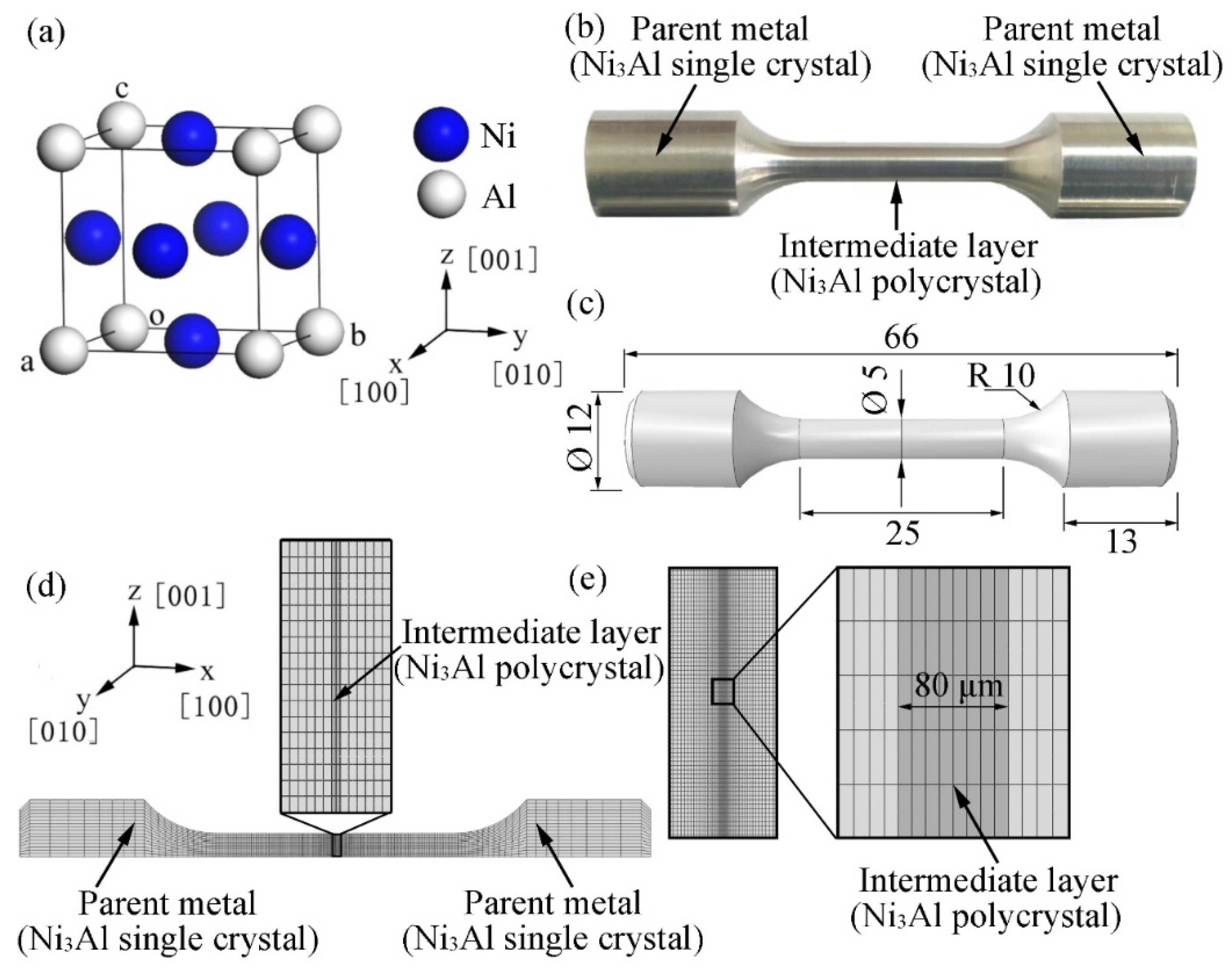
2. Simulation Methods and Details

Intermetallic compound Ni3Al has a face-centered cubic lattice structure and Pm-3m space group; its lattice constant is a = 3.572 Å [22], as shown in Figure 1a. In this study, the CASTEP program [23] was used to perform first-principles calculations based on DFT. In the lattice-structure optimization and elastic-constant calculation, the local density approximation proposed by Ceperley and Alder was applied to investigate the exchange-correlation potential [24]. In addition, Vanderbilt ultra-soft pseudo potentials [25] and the Broyden–Fletcher–Goldfarb–Shanno algorithm [26] were also used during the lattice-structure optimization. The energy cutoff was taken as 600 eV, the k-points were set to 10 × 10 × 10, and the convergence tolerance of energy was set as 5.0 × 10⁻⁶ eV/atom. The self-consistent field had a convergence accuracy of 5.0 × 10⁻⁷ eV/atom, and the maximum ionic Hellmann–Feynman force was 0.01 eV/Å. The stress deviation during the calculation was less than 0.02 GPa.
The length of the TLP bonding sample, the diameter of the joint, and the thickness of the intermediate layer were 66 mm, 5 mm, and 80 μm, respectively, as shown in Figure 1b,c.
A simple tension load of 50 MPa was applied to the ends of the sample at room temperature. Given the axisymmetry of the sample, a one-fourth (1/4) symmetric FE model was established for three-dimensional (3D) finite element analysis (FEA) (Figure 1d), which can drastically reduce calculations and save time. The FE model comprised the parent alloy (i.e., single-crystalline Ni3Al) and an intermediate-layer alloy (i.e., polycrystalline Ni3Al), and there were 50,688 elements and 221,201 nodes. Obviously, the mesh density of the TLP bonded joint in the model, as further shown in the magnification of the indicated zone in Figure 1d, was not sufficiently fine to accurately analyze the localized stress and strain distribution; thus, the submodel method was adopted in the FEA on the basis of Saint-Venant’s principle, as displayed in Figure 1e. The location of the submodel is the same as the indicated zone in Figure 1d, and the submodel comprises 186,850 elements and 775,736 nodes. All FE calculations were performed with the ABAQUS 2018 software, and quadratic complete integration (C3D20) and full Newton iteration were employed to accurately solve the stress–strain relationship.

3. Results and Discussion

3.1. Mechanical Properties of Ni3Al

In the elastic stage, the stress and strain relationship can be described by Hooke’s law: σij = Dijklεij, where Dijkl denotes the elastic constants. According to the symmetry of the crystal lattice, the elastic stress–strain matrix [Dijkl] of single-crystalline Ni3Al can be expressed as
( σ 11 σ 22 σ 33 σ 12 σ 13 σ 23 ) = ( D 1111 D 1122 D 1133 0 0 0 D 2222 D 2233 0 0 0 D 3333 0 0 0 D 1212 0 0 S y m . D 1313 0 D 2323 ) ( ε 11 ε 22 ε 33 γ 12 γ 13 γ 23 )
where σij, εij, and γij are the stresses, normal strains, and shearing strains respectively. The stiffness matrix [Dijkl] was calculated by linearly fitting four small strains (±0.001 and ±0.003) under nine deformation conditions (see Supplementary Figure S1); the calculated elastic constants are listed in Table 1. The flexibility matrix [Sijkl] was calculated as the inverse matrix of the stiffness matrix [Dijkl], i.e., [Sijkl] = [Dijkl]−1; the results for elastic constants Sijkl are given in Table 2.
According to the Voigt–Reuss–Hill approximation method [28], the bulk modulus (B) and shear modulus (G) of polycrystalline Ni3Al can be calculated by Equations (1) and (2), respectively:
B = 1 2 [ 1 3 S 1111 + 6 S 1122 + 1 3 ( D 1111 + 2 D 1122 ) ] ,
G = 1 2 [ 15 4 S 1111 4 S 1122 + 3 S 1212 + 1 5 ( D 1111 D 1122 + 3 D 1212 ) ] .
The calculated values of B and G are 186.72 GPa and 78.86 GPa respectively. Moreover, the elastic modulus (Young’s modulus, E) and Poisson’s ratio (v) can be evaluated by Equations (3) and (4) respectively:
E = 9 B G 3 B + G ,
ν = 3 B E 6 B .
The calculated values of E and v for polycrystalline Ni3Al are 207.38 GPa and 0.315 respectively; these values are similar to the experimental values E = 203.1 GPa and v = 0.305 at room temperature [29].

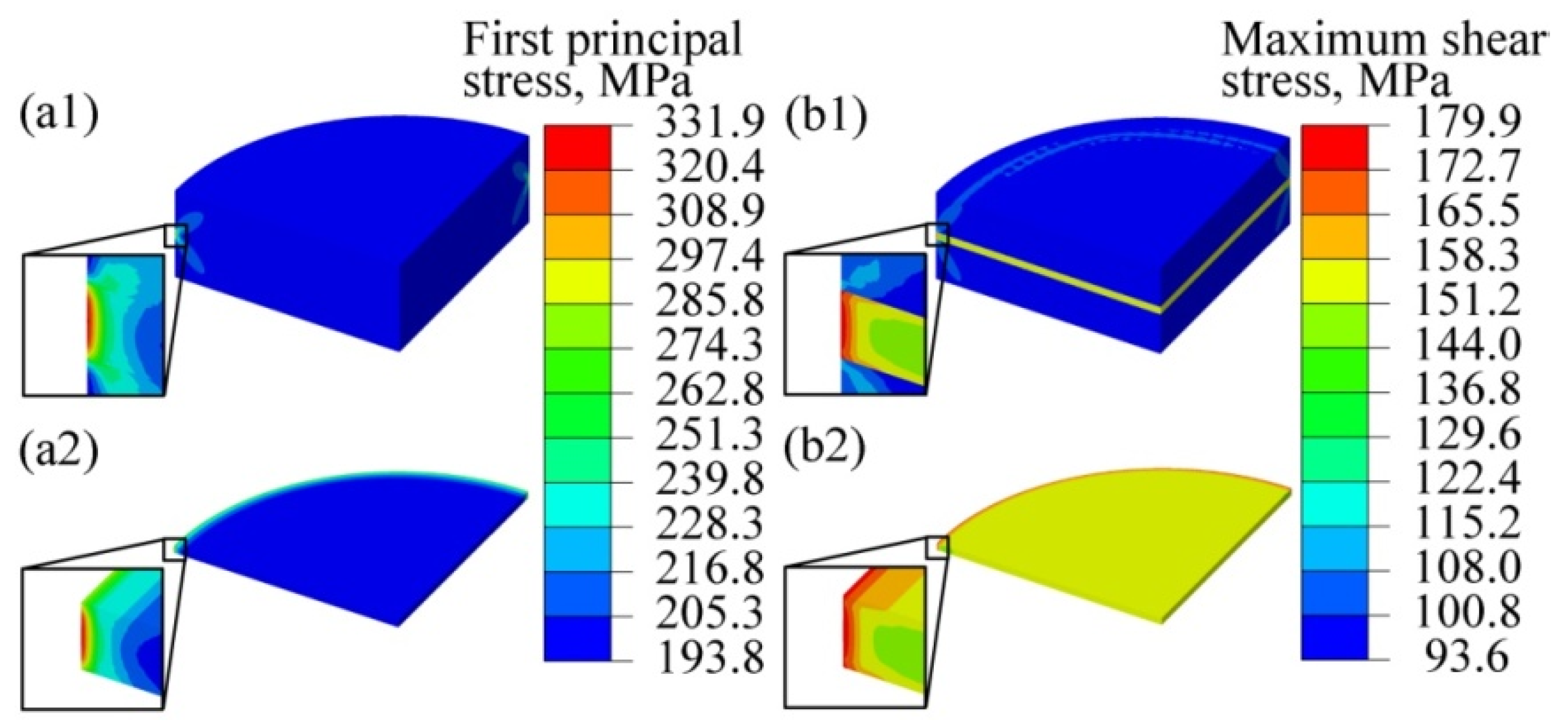
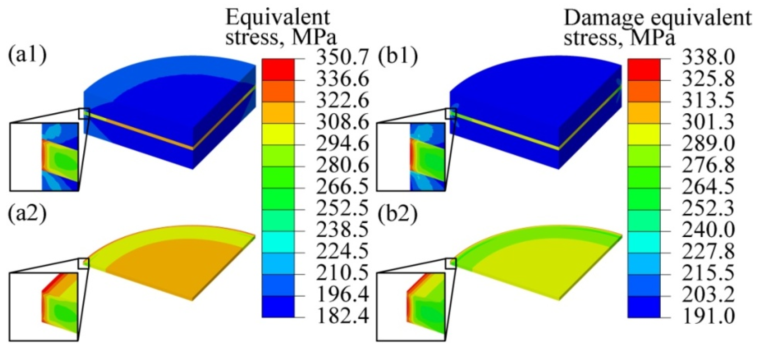
3.2. Stress Concentration Induced by the State of Crystal Orientation

The calculated elastic constants Dijkl and the aforementioned mechanical properties were used in FEA for a tension load of 50 MPa, which is much less than the yield strength of Ni3Al (>350 MPa [30]). Covalent bonding and ionic bonding are well known to lead to brittleness in intermetallic compounds. Herein, the crystal plane (111) was selected to evaluate the chemical bonds between Ni–Ni and Ni–Al atoms, and the electron density in the (111) planes was calculated via DFT (Figure 2). From the overlap of the electron densities of Ni–Ni atoms, it is inferred that covalent bonds exist. Meanwhile, the electron charge density around Ni atoms is 1.0, whereas that close to Al atoms is 0.0, indicating that the electrons of Al atoms move toward the Ni atoms and that Ni and Al atoms are bonded together by ionic bonds. Therefore, we assumed that Ni3Al exhibits some brittleness.
According to the maximum principal stress theory, in a simple tension test, failure occurs if the first principal stress (σ1) reaches the elastic limit stress. Figure 3a1,a2 display the distribution of σ1 in the submodel and the intermediate layer, where the σ1 is maximally localized at the edge of the intermediate layer (refer to the red contour). The maximum σ1 and average σ1 are 331.9 and 200.1 MPa respectively, and the ratio of the maximum σ1 to average σ1 is 1.66. Clearly, different states of crystal orientation induce stress concentration in the intermediate layer, which may lead to failure in this layer. Moreover, Pugh et al. [31] proposed that the ratio between the bulk modulus and the shear modulus (i.e., B/E) can be used to evaluate the ductility of a material; they also proposed that ductile materials have B/E values greater than 1.75. The calculated B/G ratio for Ni3Al in this study is 2.37; we therefore speculate that Ni3Al also has some ductility, which can also be verified from the experimental results reported elsewhere [32].
The maximum shear stress theory assumes that failure occurs when the maximum shear stress reaches the yield point measured in the simple tension test, which is often used during the strength design of ductile materials. Because the maximum principal stress theory mentioned above is not always suitable for ductile materials, the maximum shear stress was used to evaluate the failure behavior of the TLP bonded joint. The maximum shear stress in each element can be expressed as
τ max = σ 1 σ 3 2 ,
where σ3 is the third principal stress. Figure 3b1,b2 show the distribution of the maximum shear stresses in the submodel of a TLP bonded joint, where the maximum shear stress is located at the edge of the intermediate layer and at the interfaces between the intermediate layer and the parent alloy (refer to the red contour in the figure). In the intermediate layer, the maximum and average τmax are 179.9 MPa and 155.9 MPa respectively, and the ratio between the maximum τmax and the average τmax is 1.15. In addition, our calculation shows that if the intermediate layer is treated as a single alloy with the same orientation as the parent alloy, no stress concentration occurs in the joint and the τmax is 100 MPa.
To consider the influence of the second principal stress σ2 on the stress concentration of a complex stress system, the von Mises stress (equivalent stress, σeq) was also calculated in this study. The von Mises hypothesis (i.e., the fourth strength theory) [33] holds that a material begins to yield when σeq reaches the yield strength and that σeq is given by Equation (6):
σ eq = ( σ 1 σ 2 ) 2 + ( σ 2 σ 3 ) 2 + ( σ 3 σ 1 ) 2 2 .
Meanwhile, to evaluate the stress triaxiality, which affects the initiation and growth of micro-voids and cracks [34] on the failure of the TLP bonded joint, the damage equivalent stress ( σ eq * ) in the joint was also investigated. It can be written as follows [34]:
σ eq = σ eq [ 2 3 ( 1 + ν ) + 3 ( 1 2 ν ) ( T σ ) 2 ] 1 2 ,
where Tσ is stress triaxiality, and
T σ = σ m / σ eq ,
σ m = ( σ 1 + σ 2 + σ 3 ) / 3 ,
where σm is the hydrostatic stress. Figure 4 shows the simulation results for σeq and σ eq * in the TLP bonded joint. Obviously, both σeq and σ eq * in the intermediate layer are greater than those in the parent alloy. The σeq and σ eq * maximally distribute at the edges of the intermediate layer and at the interfaces between the intermediate layer and parent alloy (refer to the red contour in the figure), the locations of which are similar to those of the maximum τmax. The maximum σeq and σ eq * in the intermediate layer are 350.7 GPa and 338.0 GPa respectively. If the intermediate layer is treated as a single alloy with the same orientation as the parent alloy, then no stress concentration occurs and the values of σeq and σ eq * are 200 MPa (see Table S1).
Elastic modulus is the principal mechanical parameter for structural materials, which can be adjusted and controlled by adding alloyed elements or performing heat treatments. Figure 5 presents the influence of the elastic modulus of the intermediate layer (Einter) on the stress concentration, wherein the elastic modulus ranges from 0.85E to 1.15E (E = 207.378 GPa). Clearly, with the decreasing elastic modulus of the intermediate layer, the maximum stresses of first principal stress, maximum shear stress, equivalent stress, and damages equivalent stress decrease linearly. The ratio between the maximum stress and the average stress is also reduced, indicating that reducing Einter can relieve the stress concentration. Also, the average stresses decrease linearly with decreasing elastic modulus of the intermediate layer (see Supplementary Figure S2). Therefore, in addition to increasing the mechanical strength of the intermediate layer, the simulation result in this study suggests that appropriately reducing the elastic modulus of the intermediate layer can also improve the mechanical strength of a TLP bonded joint. To verify this opinion, additional experimental work was also carried out.
In the experiment, single-crystalline Ni3Al-based superalloy (named IC10 alloy) samples were prepared by TLP bonding process in a high vacuum diffusion furnace (Centorr Vacuum Industries, Workhorse II, Nashua, NH, USA) and the bonding temperature, time, and pressure were 1250 °C, 6 h, and 5 MPa respectively. The samples of TLP bonded joints and their geometry have been given in Figure 1b,c above, and the grain boundary and crystal orientation in a typical zone in the joint are presented in Supplementary Figure S3. By nanoindentation testing, as illustrated in Supplementary Figure S4, the elastic modulus and hardness of the parent alloy and intermediate-layer alloy were measured. Test results show that the average elastic modulus of parent alloy (Eparent) and the average elastic modulus of intermediate-layer alloy Einter are 221.4 GPa and 208.5 GPa respectively (see Supplementary Figure S5), and the ratio of Einter to Eparent (i.e., Einter/Eparent) is 0.942. Then, to reduce Einter and Einter/Eparent, post weld heat treatment (PWHT) was carried out in a heat treatment furnace (SG-QF1400, Shanghai, China). During PWHT, samples of TLP bonded joints were heated to about 1200°C and held for 6 h, and then cooled down in air to room temperature. Because that Boron was added to the intermediate-layer alloy as a melting-point depressant, the atomic percent of Boron in the intermediate-layer alloy was much higher than that in the parent alloy before PWHT. In the PWHT, Boron atoms diffused from the intermediate layer to the parent alloy. As the result of solution strengthening, after PWHT, Eparent increased to 223.7 GPa while Einter decreased to 205.4 GPa, and Einter/Eparent was reduced to 0.918. According to the result of tensile testing, the average tensile strength after PWHT is 819.0 MPa at room temperature, which is higher than before PWHT (i.e., 798.0 MPa) as shown in Supplementary Figure S6. Clearly, the decrease of Einter or Einter/Eparent can improve the mechanical strength of a TLP bonded joint, which supports the simulation result in the manuscript. Notably, the ideal strength of the TLP bonded joint should be the same as or practically be as close as possible to the strength of the parent alloy. Usually, achieving a mechanical strength of a TLP bonded joint greater than 90% of the mechanical strength of a single crystal is difficult in experiments. To further improve the mechanical strength of TLP bonded joints, sufficient attention should be devoted to the stress concentration caused by the different states of crystal orientation between the parent alloy and intermediate layer.

4. Conclusions

Elastic constants of single-crystalline Ni3Al as well as the elastic modulus, shear modulus, and the Poisson’s ratio of polycrystalline Ni3Al were calculated via DFT, and the calculation results were subsequently verified against previously reported experimental data. Based on the calculated mechanical properties of both single-crystalline and polycrystalline Ni3Al, 3D FEA was used to characterize the mechanical behavior of the TLP bonded joint of single-crystalline Ni3Al under a simple tension load. The simulation results revealed obvious stress concentrations in the joint as a result of different states of crystal orientation between the parent metals (single crystals) and intermediate layer (polycrystals), which will lead to failure in the polycrystalline Ni3Al and thereby weaken the mechanical strength of the TLP bonded joint. The maximum values of the first principal stress, maximum shear stress, equivalent stress, and the damages equivalent stress in the joint decrease linearly with decreasing elastic modulus of the intermediate layer; thus, reducing the elastic modulus of the intermediate layer can relieve the stress concentration and benefit the mechanical reliability of a TLP bonded joint, which can be verified by experiments.

Supplementary Materials

The following are available online at https://www.mdpi.com/1996-1944/12/17/2765/s1, Figure S1: The strain conditions for deriving nine elastic stiffness coefficients; Figure S2: Relationship between the average stress and elastic modulus of intermediate layer; Figure S3: The grain boundary and crystal orientation in the TLP bonded joint: (a) SEM-EBSD image of the joint, (b) grain boundary in the joint; (c) all Euler map; and (d) IPF-Y0 map. The instrument used is FEI Quanta 650F+HKL Channel 5; Figure S4: Nanoindentation test: (a) SEM image of a typical zone in TLP bonded joint; and (b) schematic of a location of nanoindentation array (Berkovich indenter, instrument: Agilent G200); Figure S5: The influence of the post weld heat treatment (PWHT) on the elastic modulus (a) and hardness (b) of parent alloy and intermediate-layer alloy; Figure S6: The tensile strengths of TLP bonded joints before and after PWHT (three samples were measured for each point; instrument: universal testing machine, GP-TS2000M); Table S1: The stress in the joint ignoring the crystal orientation of intermediate layer.

Author Contributions

H.Q. and Y.Y. conceived and designed the research; H.Q., T.K., and Q.L. performed the first principles calculation and analyzed the data; Q.L., X.Y., and H.G. carried out the experimental study; T.K. wrote the manuscript; X.Y. and F.L. reviewed and edited the manuscript. All authors read and approved the final manuscript.

Funding

This research was funded by Implementing Innovation-Driven Development Capacity Building Special Funds project of Guangdong Academy of Sciences (2018GDASCX-1005 & 2018GDASCX-0113), Key Program for International Cooperation of Science and Technology (China-Ukraine, 2015DFR50310).

Conflicts of Interest

The authors declare no conflict of interest.

References

  1. Caron, P.; Khan, T. Evolution of Ni-based superalloys for single crystal gas turbine blade applications. Aerosp. Sci. Technol. 1999, 8, 513–523. [Google Scholar] [CrossRef]
  2. Zhang, P.; Hu, C.; Ding, C.G.; Zhu, Q.; Qin, H.Y. Plastic deformation behavior and processing maps of a Ni-based superalloy. Mater. Des. 2015, 65, 575–584. [Google Scholar] [CrossRef]
  3. Smith, T.M.; Rao, Y.; Wang, Y.; Ghazisaeidi, M.; Mills, M.J. Diffusion processes during creep at intermediate temperatures in a Ni-based superalloy. Acta. Mater. 2017, 141, 261–272. [Google Scholar] [CrossRef]
  4. Paulonis, D.F.; Duvall, D.S.; Owczarski, W.A. Diffusion bonding utilizing transient liquid phase. U.S. Patent 3678570, 25 July 1972. [Google Scholar]
  5. Khakian, M.; Nategh, S.; Mirdamadi, S. Effect of bonding time on the microstructure and isothermal solidification completion during transient liquid phase bonding of dissimilar nickel-based superalloys In738lc and nimonic 75. J. Alloys Compd. 2015, 653, 386–394. [Google Scholar] [CrossRef]
  6. Cook, G.O.; Sorensen, C.D. Overview of transient liquid phase and partial transient liquid phase bonding. J. Mater. Sci. 2011, 46, 5305–5323. [Google Scholar] [CrossRef] [Green Version]
  7. Yang, Z.W.; Lian, J.; Cai, X.Q.; Wang, Y.; Wang, D.P.; Liu, Y.C. Microstructure and mechanical properties of Ni3Al-based alloy joint transient liquid phase bonded using Ni/Ti interlayer. Intermetallics 2019, 109, 179–188. [Google Scholar] [CrossRef]
  8. Ai, C.; Li, S.S.; Zhao, X.B.; Zhou, J.; Guo, Y.J.; Sun, Z.P.; Song, X.D.; Gong, S.K. Influence of solidification history on precipitation behavior of TCP phase in a completely heat-treated Ni3Al based single crystal superalloy during thermal exposure. J. Alloys Compd. 2017, 722, 740–745. [Google Scholar] [CrossRef]
  9. Luan, X.H.; Qin, H.B.; Liu, F.M.; Dai, Z.B.; Yi, Y.Y.; Li, Q. The mechanical properties and elastic anisotropies of cubic Ni3Al from first principles calculations. Crystals 2018, 8, 307. [Google Scholar] [CrossRef]
  10. Shah, D.M. Orientation dependence of creep behavior of single crystal γ′ (Ni3Al). Scripta Metal. 1983, 17, 997–1002. [Google Scholar] [CrossRef]
  11. Wang, W.; Jiang, C.B.; Lu, K. Deformation behavior of Ni3Al single crystals during nanoindentation. Acta Mater. 2003, 51, 6169–6180. [Google Scholar] [CrossRef]
  12. Wen, Z.X.; Zhang, D.X.; Li, S.W.; Yue, Z.F.; Gao, J.Y. Anisotropic creep damage and fracture mechanism of nickel-base single crystal superalloy under multiaxial stress. J. Alloys Compd. 2017, 692, 301–312. [Google Scholar] [CrossRef]
  13. Reed, R.C.; Tao, T.; Warnken, N. Alloys-by-design: Application to nickel-based single crystal superalloys. Acta Mater. 2009, 57, 5898–5913. [Google Scholar] [CrossRef]
  14. Fleischmann, E.; Miller, M.K.; Affeldt, E.; Glatzel, U. Quantitative experimental determination of the solid solution hardening potential of rhenium, tungsten and molybdenum in single-crystal nickel-based superalloys. Acta Mater. 2015, 87, 350–356. [Google Scholar] [CrossRef] [Green Version]
  15. Huang, M.; Zhu, J. An overview of rhenium effect in single-crystal superalloys. Rare Metals 2016, 35, 127–139. [Google Scholar] [CrossRef]
  16. Ghoneim, A.; Ojo, O.A. On the influence of boron-addition on tlp bonding time in a Ni3Al-based intermetallic. Intermetallics 2010, 18, 582–586. [Google Scholar] [CrossRef]
  17. Ojo, O.A.; Ghoneim, O.J.; Hunedy, J. Transient liquid phase bonding of single crystal Ni3Al-based intermetallic alloy. In Proceedings of the International Brazing and Soldering Conference, Las Vegas, NV, USA, 22–25 April 2012. [Google Scholar]
  18. Chai, L.; Huang, J.H.; Hou, J.B.; Lang, B.; Wang, L. Effect of holding time on microstructure and properties of transient liquid-phase-bonded joints of a single crystal alloy. J. Mater. Eng. Perform. 2015, 24, 2287–2293. [Google Scholar] [CrossRef]
  19. Guo, W.; Wang, H.Y.; Jia, Q.; Peng, P.; Zhu, Y. Transient liquid phase bonding of nickel-base single crystal alloy with a novel Ni-Cr-Co-Mo-W-Ta-Re-B amorphous interlayer. High Temp. Mat Pr-isr. 2017, 36, 677–682. [Google Scholar] [CrossRef]
  20. Sheng, N.C.; Liu, J.D.; Jin, T.; Sun, X.F.; Hu, Z.Q. Precipitation behaviors in the diffusion affected zone of tlp bonded single crystal superalloy joint. J. Mater. Sci. Technol. 2015, 31, 129–134. [Google Scholar] [CrossRef]
  21. Polkowski, W.; Pęczek, E.; Zasada, D.; Komorek, Z. Differential speed rolling of Ni3Al based intermetallic alloy—effect of applied processing on structure and mechanical properties anisotropy. Mater. Sci. Eng. A 2015, 647, 170–183. [Google Scholar] [CrossRef]
  22. Mohan Rao, P.V.; Suryanarayana, S.V.; Satyanarayana Murthy, K.; Nagender Naidu, S.V. The high-temperature thermal expansion of Ni3Al measured by X-ray diffraction and dilation methods. J. Phys. Condens. Mat. 1989, 1, 5357–5361. [Google Scholar]
  23. Segall, M.D.; Lindan, P.J.D.; Probert, M.J.; Pickard, C.J.; Hasnip, P.J.; Clark, S.J.; Payne, M.C. First-principles simulation: Ideas, illustrations and the CASTEP code. J. Phys. Condens. Mat. 2002, 14, 2717–2744. [Google Scholar] [CrossRef]
  24. Ceperley, D.M.; Alder, B.J. Ground state of the electron gas by a stochastic method. Phys. Rev. Lett. 1980, 45, 566–569. [Google Scholar] [CrossRef]
  25. Vanderbilt, D. Soft self-consistent pseudopotentials in a generalized eigenvalue formalism. Phys. Rev. B 1990, 41, 7892–7895. [Google Scholar] [CrossRef] [PubMed]
  26. Pfrommer, B.G.; Côté, M.; Louie, S.G.; Cohen, M.L. Relaxation of crystals with the quasi-Newton method. J. Comput. Phys. 1997, 131, 233–240. [Google Scholar] [CrossRef]
  27. Kayser, F.X.; Stassis, C. The elastic constants of Ni3Al at 0 and 23.5 °C. Phys. Status Solidi A 1981, 64, 335–342. [Google Scholar] [CrossRef]
  28. Hill, R. The elastic behaviour of a crystalline aggregate. Proc. Phys. Soc. A 1952, 65, 349. [Google Scholar] [CrossRef]
  29. Prikhodko, S.V.; Yang, H.; Ardell, A.J.; Carnes, J.D.; Isaak, D.G. Temperature and composition dependence of the elastic constants of Ni3Al. Metall. Mater. Trans. A 1999, 30, 2403–2408. [Google Scholar] [CrossRef]
  30. Yoo, M.H.; Liu, C.T. Effect of prestress on tensile yield strength of a Ni3Al alloy. J. Mater. Res. 2011, 3, 845–847. [Google Scholar] [CrossRef]
  31. Pugh, S.F. XCII. Relations between the elastic moduli and the plastic properties of polycrystalline pure metals. Dublin Philos. Mag. J. Sci. 1954, 45, 823–843. [Google Scholar] [CrossRef]
  32. Aoki, K.; Izumi, O. On the ductility of the intermetallic compound Ni3Al. J. Jpn. Inst. Met. 1977, 41, 170–175. [Google Scholar] [CrossRef]
  33. Kolupaev, V.A. Equivalent Stress Concept For Limit State Analysis; Springer: Darmstad, Germany, 2018; Volume 86, pp. 16–18. [Google Scholar]
  34. Lemaitre, J. A Course On Damage Mechanics, 2nd ed.; Springer: Berlin, Germany, 2012; pp. 39–46. [Google Scholar]
Figure 1. TLP bonded joint sample: (a) crystal structure of cubic Ni3Al, (b) a sample prepared in experiments, (c) the geometry of the sample for FE modeling (mm), and (d) the one-fourth 3D FE model and (e) submodel.
Materials 12 02765 g001
Figure 2. Distribution of electron density in the (111) crystal plane.
Materials 12 02765 g002
Figure 3. Simulation results of first principal stresses and shear stress: first principal stress in (a1) the TLP bonded joint and (a2) the intermediate layer; and shear stress in (b1) the TLP bonded joint and (b2) the intermediate layer.
Materials 12 02765 g003
Figure 4. Simulation results of the von Mises equivalent stress and the damage equivalent stress: von Mises equivalent stress in the (a1) TLP bonded joint and (a2) intermediate layer, and damage equivalent stress in the (b1) TLP bonded joint and (b2) intermediate layer.
Materials 12 02765 g004
Figure 5. Influence of elastic moduli on (a) the maximum stresses and (b) the ratio between the maximum stress and the average stress in the TLP bonded joint.
Materials 12 02765 g005
Table 1. Elastic constants Dijkl for single-crystalline Ni3Al.
Elastic ConstantD1111D1122D1133D2222D2233D3333D1212D1313D2323
Present work240.10160.03160.03240.10160.03240.10123.83123.83123.83
Experiment [27]224.3148.6148.6224.3148.6224.3125.8125.8125.8
Table 2. Elastic constants Sijkl for single-crystalline Ni3Al.
Elastic ConstantS1111S1122S1133S2222S2233S3333S1212S1313S2323
Present work0.009−0.004−0.0040.009−0.0040.0090.0080.0080.008

