Article

Chemiluminescence-Based Analysis of Syngas/Diesel Dual-Fuel Combustion in an Optically Accessible Engine

by
Ricardo Rabello de Castro
1,
Pierre Brequigny
1,* and
Christine Mounaïm-Rousselle
1,2
1
PRISME, Université d’Orléans, INSA-CVL, EA 4229, F45072 Orléans, France
2
Institut Universitaire de France (IUF), F75231 Paris Cedex 05, France
*
Author to whom correspondence should be addressed.
Energies 2026, 19(9), 2042; https://doi.org/10.3390/en19092042
Submission received: 17 March 2026 / Revised: 16 April 2026 / Accepted: 18 April 2026 / Published: 23 April 2026

Abstract

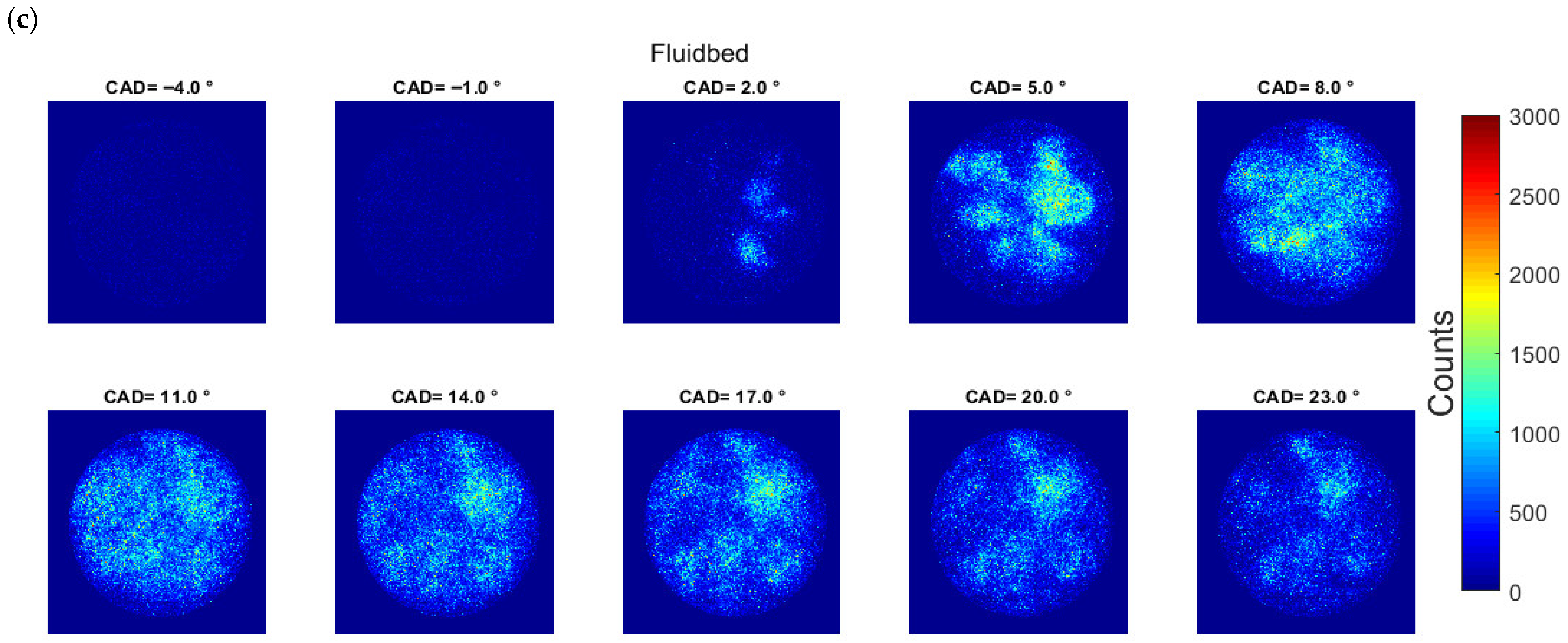
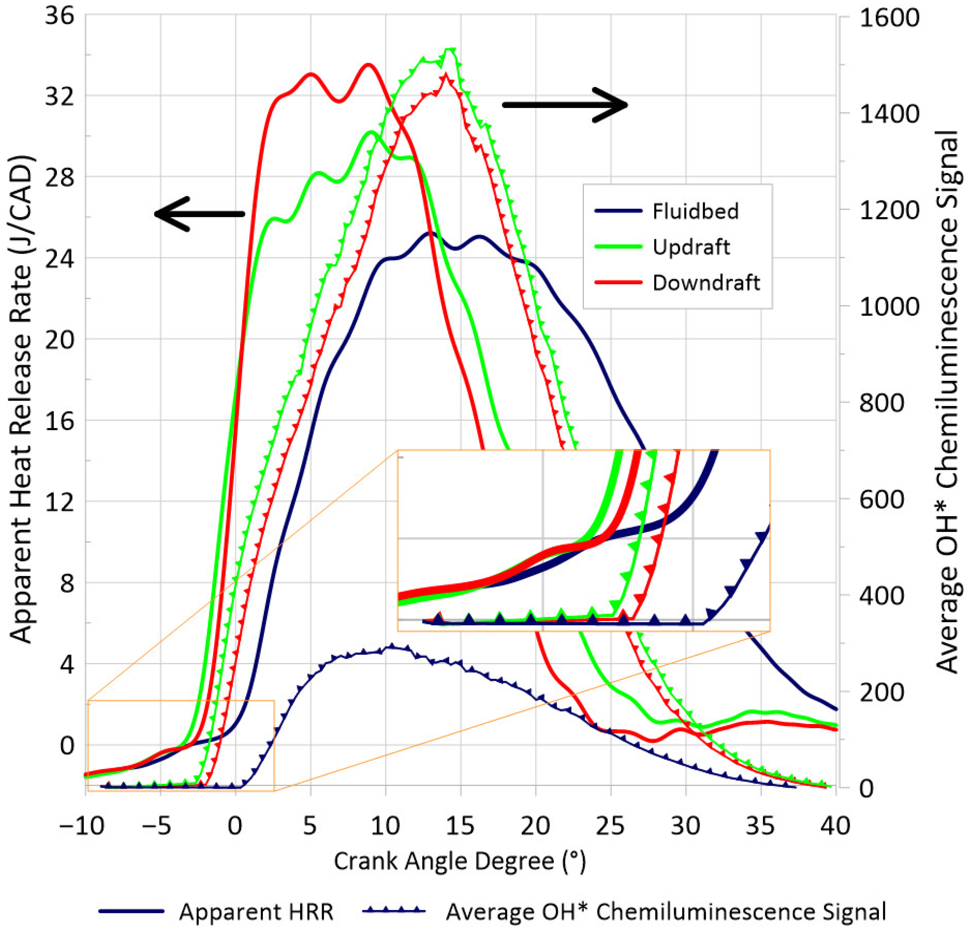
Syngas (synthesis gas) is a promising gaseous biofuel for small-scale power generation, but its highly variable composition, which depends on the biomass source and gasification process, poses challenges for engine optimization. This study investigates syngas–diesel dual-fuel combustion in an optically accessible engine using chemiluminescence imaging of OH*, CH*, and CH2O* to characterize ignition and flame development. Three representative syngas compositions—Downdraft, Updraft, and Fluidbed—were examined. The Fluidbed composition exhibited the weakest OH* signal, approximately one-third of that observed for the other two, primarily due to its higher CO2 dilution and lower H2 content. Ignition delay trends were strongly correlated with dilution level: Downdraft and Updraft showed similar delays despite different H2/CO ratios, while larger CO2 shares led to longer delays and flattened heat-release rates. CH* and CH2O* chemiluminescence showed better agreement with combustion timing than OH*. Methane enrichment enhanced flame propagation and reduced ignition delay, partially offsetting CO2 dilution effects.

1. Introduction

The energy sector is under significant pressure to transition to clean and renewable energy sources. To meet the ambitious goal of achieving net-zero carbon emissions by 2050, a target set by over 100 countries [1], all sectors of the economy must undergo substantial transformation. While many believe that a complete shift to a combustion-free energy sector is the only viable solution, achieving this is far from straightforward.
In this context, biofuels emerge as a promising alternative reducing global CO2 emissions more affordably and with simpler technologies. One such biofuel is ‘syngas’, also known as producer gas or wood gas, which refers to gaseous fuel produced through Municipal Solid Waste (MSW) or biomass gasification. This process converts large biomass molecules into simpler gas molecules (H2, CO, CO2, etc.). Syngas, which is in essence a mixture of hydrogen (H2) and carbon monoxide (CO), should not be confused with biogas, which is a mixture of methane (CH4) and CO2, produced from landfilling and methanation. Gasification, as a waste-to-energy process, competes with the two alternatives. While the carbon footprint of syngas is higher than that of landfilling [2], it can, in some cases, outperform biogas production [3]. However, from a Life Cycle Analysis (LCA) perspective, how efficient it is and how much Green-House Gas (GHG) is produced by waste after-treatment should be assessed on a case-by-case basis. As demonstrated by Dastjerdi et al. [4], gasification-pyrolysis could produce less GHG than landfilling, using MSW as feedstock.
The biomass type [5] and the gasification process itself [6] affect the syngas composition: a typical one includes H2, CO and CH4 with a volume concentration range of 10~20%, 13~24% and 0~7% respectively [6,7]. Additionally, air-fed gasifiers produce syngas compositions with 10~20% CO2 and 45~60% N2. In contrast, oxygen- or steam-based gasification permit a strong reduction in N2 fraction, but often come with higher costs and are limited to specific use cases [7,8]. The three syngas compositions tested in this study replicate those of Bridgwater [6] and are from three types of gasifiers. Two are fixed-bed and one is a fluidized-bed gasifier, presenting different dilution and H2/CO ratios, which influences the engine-relevant combustion characteristics, such as the laminar flame speeds [9] and the ignition delays [10].
Syngas is a biofuel that can be used in Combined Heat and Power units (CHP), that can be based on Internal Combustion Engines (ICEs) or on Gas Turbines (GTs). Since the auto-ignition temperature of syngas is rather high [11], a syngas-fueled ICE needs a source of ignition as an electrical spark or a pilot injection of a more reactive fuel [12]. The latter is usually known as a dual-fuel engine, and has the advantage of providing flexibility along with greater fuel-conversion efficiency [12]. The literature reports several studies on dual-fuel syngas ICEs, addressing engine efficiency and emissions across different syngas compositions [13,14,15,16,17]. Nevertheless, a deeper understanding of the combustion dynamics of the syngas dual-fuel operation is required to properly set the operating conditions of the engine, as a function of the syngas composition.
Optical diagnostics provide a direct window into the in-cylinder combustion processes, enabling spatially and temporally resolved characterization of ignition timing, flame propagation, soot formation, and flow-field dynamics. Among the most informative targets are chemically excited radical species whose emissions display distinct combustion regimes. In the present case, OH* marks the high-temperature reaction front, CH* delineates active flame zones, and CH2O* is associated with low-temperature pre-ignition chemistry and cool-flame reactions [18,19,20].
Two established detection strategies are used to track these species. Natural chemiluminescence (CL) records the spontaneous photon emission from electronically excited radicals, requiring only a band-pass filter and an intensified camera. This technique is well-suited to optically accessible engines where access is geometrically constrained. Its main limitation is the line-of-sight integration, inherent to this technique, which precludes depth-resolved species quantification. In contrast, planar laser-induced fluorescence (PLIF) excites the target species with a tunable laser sheet, yielding two-dimensional concentration maps with potential for quantitative species measurements. However, this comes at the cost of substantially greater experimental complexity, as each target radical requires a dedicated laser wavelength and precise optical alignment.
A third approach was recently introduced by Mancaruso et al. [21], who demonstrated high-speed infrared imaging as a non-intrusive diagnostic capable of capturing qualitative fuel-vapor distributions and identifying ignition sites under both low- and high-temperature conditions. While this technique extends the diagnostic toolkit beyond the visible/UV spectrum, it requires a specialized high-speed IR camera, limiting its accessibility.
The combustion-emitted radiation in the visible and near-visible spectral range results from the superposition of two physically distinct contributions: soot incandescence and radical chemiluminescence. Soot incandescence produces a continuous broadband spectrum, with peak emission intensity governed by the solid particles’ temperatures. In contrast, radical chemiluminescence yields spectrally narrow emission bands generated when electronically excited species relax toward lower-energy states [19]. Radical chemiluminescence is a narrow-band emission, which is a result of the photons emitted during the electronic transitions from a self-excited to a more stable molecule or species [20], overlaid on top of the broadband emission from the CO2* continuum [22]. In a dual-fuel configuration where a diesel-type pilot is delivered in minimal quantities, solely to initiate combustion of the premixed fuel, the overall natural luminosity becomes dominated by chemiluminescence (CL) rather than soot incandescence [23]. For syngas in particular, the H2 content drives OH* as the principal radiative species, which differs from conventional hydrocarbon combustion behavior and its characteristic UV emission peak allowing spectral separation from CH* signals [24]. The OH* chemiluminescence signal exhibits its main intensity peak in the ultraviolet region, which allows it to be spectrally separated from CH* chemiluminescence. Nevertheless, Huang et al. [24] reported that increasing CO and/or CO2 in the mixture can markedly attenuate the OH* intensity level. For syngas combustion initiated by a diesel-type pilot injection, the injection strategy can also promote the emergence of low-temperature pre-reaction chemistry prior to the main high-temperature heat release [25], mainly identified by excited formaldehyde radicals (CH2O*), as observed in HCCI combustion [26]. In dual-fuel operation, monitoring OH* and CH2O* can provide a practical means to separate the low-temperature (low-T) ignition stage from the subsequent high-temperature (high-T) ignition event. Still, for some mixture compositions and reactivity levels, the emissions associated with the pilot-fuel combustion, and those produced by the premixed syngas burn, can remain ambiguous [25].
A number of optical engine investigations have examined dual-fuel combustion with natural gas (NG) or methane initiated by a diesel pilot injection [27,28], and similar approaches have only been extended to ammonia-fueled dual-fuel operation more recently [29,30]. Syngas has not received the same level of attention in optical dual-fuel engine investigations to date. The limited optical studies available for syngas have largely been carried out in spark-ignition (SI) engines [31,32], where the emphasis is typically on fully premixed flame propagation and overall flame development rather than on imaging or tracking specific radicals and intermediate species.
Solferini de Carvalho et al. [32] examined premixed combustion of an SI optical engine, systematically enriching a representative syngas blend (H2–CO–CH4–CO2–N2), increasing the H2 fraction from 14% (baseline composition) up to 62%. Their experiments were conducted in an optically accessible SI engine (CR = 9.68:1) equipped with an intensified high-speed camera to visualize and quantify flame evolution. They reported that turbulent flame speed rose approximately linearly with H2 content, and that a mixture containing 24% H2 exhibited a flame propagation speed comparable to that of neat CH4. In addition, increasing H2 led to smoother flame fronts, with a clear reduction in flame wrinkling. As noted in [33], the ratio between turbulent and laminar flame velocities suggests that, under H2 enrichment, the effect of turbulence on flame acceleration is less significant than the influence of mass diffusivity and chemical reaction rate. These results are consistent with other optical SI engine studies on reformer gas mixtures (H2–CO–CO2) [33,34]. Martinez-Boggio et al. [35] also recently confirmed these results by analyzing natural luminescence images in the UV-visible spectrum along the entire cycle to follow the flame front development, for different compositions of H2-CO-CO2-N2.
Hydrogen addition predictably enhances flame propagation and tends to stabilize combustion, yet the largest turbulent-to-laminar flame speed ratio is not necessarily obtained at the highest H2 fraction, but can instead occur for mixtures containing larger CH4 and/or diluent fractions. For typical syngas blends, the turbulent-to-laminar ratio is in the order of 20, highlighting how turbulence strongly amplifies a comparatively low laminar flame speed, whereas for undiluted H2/CO mixtures the ratio is closer to 10 [32].
In an NG dual-fuel optical engine study, using methane as a surrogate, Ahmad et al. [27] investigated how the premixed methane/air equivalence ratio influences ignition delay, while also varying intake temperature and the diesel pilot energy share. At the lowest pilot contribution (16.5% of total fuel energy), soot incandescence “bright spots” were reported only late in the combustion event and remained localized near the injector tip, and increasing the pilot fraction from 16.5% to 27.5% produced only a small reduction in the measured ignition delay times (IDTs).
Srna et al. [36] examined chemiluminescence signals from lean premixed natural gas combustion initiated by a dodecane pilot in a rapid compression–expansion machine. They showed that the measured natural luminosity contains strong contributions from soot incandescence as well as OH* and CH* emission, with additional broadband interference associated with CO2*, CHO*, and CH2O* chemiluminescence. A notable outcome of their analysis was that CH* chemiluminescence is essentially confined to the onset of ignition and the interval dominated by pilot-fuel combustion. They further extended their work by applying CH2O PLIF measurements [18]. Their results indicated that, depending on the diesel fraction, soot incandescence can contaminate natural luminosity-based interpretations, so that localized bright spots may still appear even when using OH* UV chemiluminescence detection around 308 nm [27,36]. Their goal was to assess why ignition delay times (IDTs) inferred from heat-release rate (HRR) analysis can differ from an IDT defined by the first detectable OH* chemiluminescence in dual-fuel operation. They reported that enriching the methane/air mixture and reducing the intake O2 concentration both suppress the OH* signal and the broadband luminosity (dominated largely by CHO*, CH2O*, and CO2* emissions), which can render difficult a reliable identification of the true ignition onset. Cheng et al. [37] combined OH* and CH2O* chemiluminescence measurements with broadband natural-luminosity imaging in a methane/diesel dual-fuel optical engine. Using CH2O* CL to represent the low-temperature stage and OH* CL to mark high-temperature ignition, they reported only a small separation between the corresponding ignition delay times. Even so, the CH2O* signal increased more rapidly than OH*, and they attributed this behavior to the short pilot injection duration, which reduced the temporal gap between the two combustion phases.
This paper presents and analyzes combustion in a syngas–diesel dual-fuel engine using chemiluminescence imaging for three syngas compositions, Downdraft, Updraft and Fluidbed (Fluidized Bed), as defined by Bridgwater [6]. First, OH* CL images and average signals are presented and discussed, followed by CH* and CH2O* CL, highlighting the role of excited-state formaldehyde during low-temperature ignition and its consumption in the second combustion stage. The effect of varying CO2 dilution and CH4 enrichment, individually on H2 + CO mixtures from the three compositions, are then assessed through changes in the averaged OH* signal to analyze its cycle-to-cycle variability.
To the best of the authors’ knowledge, this study is the first to use chemiluminescence imaging to systematically examine syngas–diesel dual-fuel combustion in an optically accessible CI engine for the representative syngas compositions defined by Bridgwater. The central question addressed here is how changes in syngas composition, particularly CO2 dilution, H2/CO balance, and CH4 enrichment, alter ignition timing, radical development, and flame evolution under dual-fuel compression–ignition conditions.

2. Experimental Set-Up and Methodology

2.1. Experimental Set-Up

The experiments were performed on an optically accessible single-cylinder research engine derived from the PSA DW10 cylinder-head architecture. Key operating conditions and hardware specifications of the test engine are summarized in Table 1.
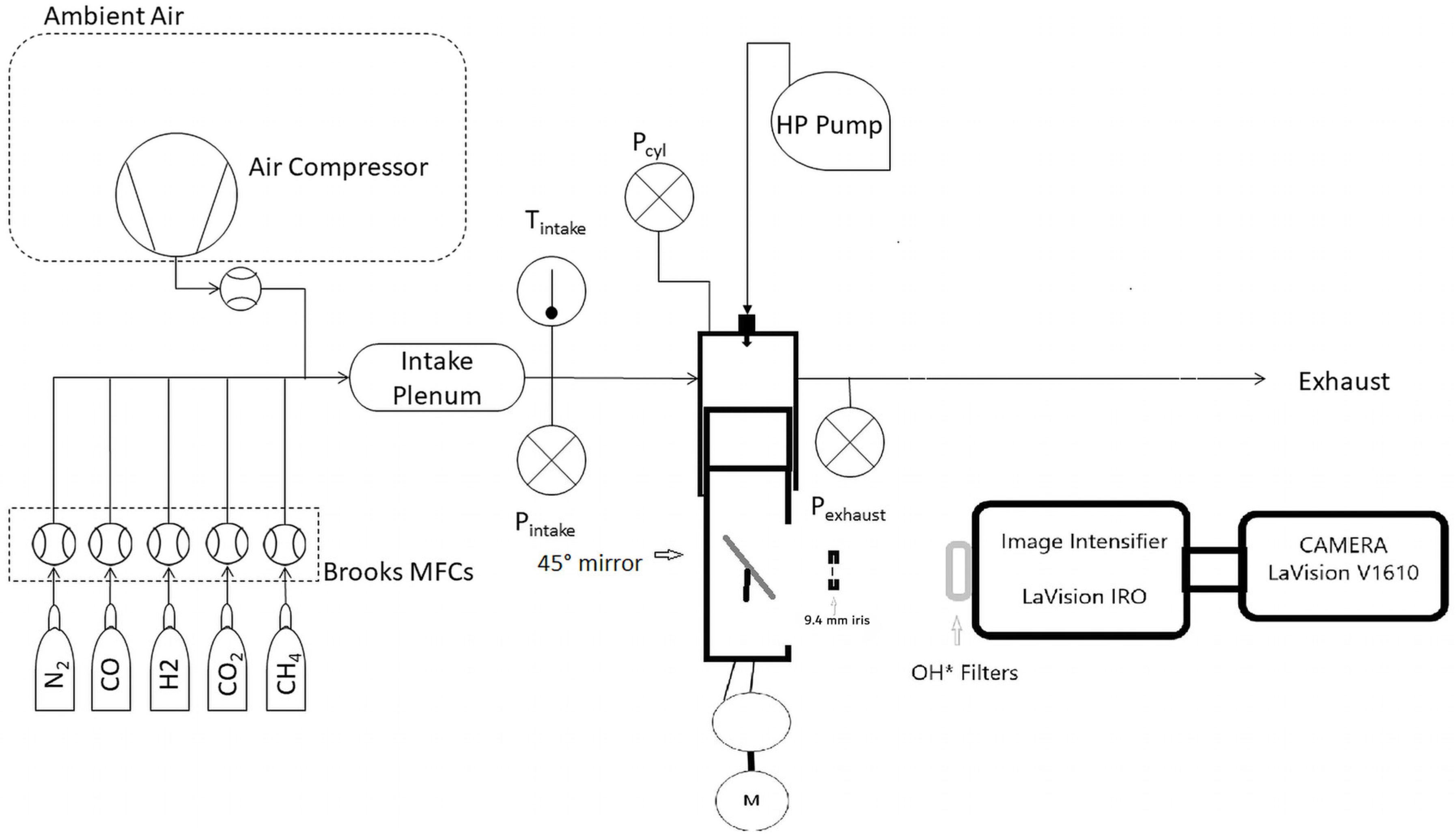
The crankshaft speed was set to 750 rpm, a common speed of European gensets, and to limit thermal and mechanical loading of the piston-mounted optical window, combustion was initiated only once every three engine cycles. A schematic overview of the full experimental arrangement is provided in Figure 1.
The intake temperature was maintained at 25 °C (298 K) and the intake pressure at 1 bar. Temperatures were recorded at the intake and the exhaust of the engine, as well as the intake and exhaust pressures. The in-cylinder pressure traces were recorded by an AVL GH15D sensor and coded every 0.1 CAD. The post-processing method was described in [17], but from the 120 recorded in-cylinder pressure cycles, only 40 are fired cycles and 80 are non-fired cycles. The apparent Heat-Release Ratio (HRR) is plotted, instead of the combustion (net) HRR, because the calculation of thermal losses is less straightforward in an optical engine and could induce interpretation errors. The apparent HRR was obtained from the standard single-zone pressure–volume formulation using Equation (1), where γ is the heat capacity of the gas in the cylinder.
H R R = γ γ 1 P d V d θ + 1 γ 1 V d P d θ
Air is first compressed and dried before passing through the Brooks mass-flow controllers. The complete flow-metering configuration is summarized in Table 2 and yields an overall uncertainty of ±2% on the intake–charge equivalence ratio. For the pilot fuel, decane (C10H22) is delivered using a Bosch CRI 2.2 common-rail injector operating at a reduced rail pressure of 200 bar, enabling stable and highly repeatable small injections. The injected mass at this reduced pressure was previously calibrated using an IAV type-K flow injector. The start of injection (SOI) was fixed at 15 CAD BTDC for all conditions, with an injection duration of 400 μs corresponding to the minimum pilot quantity required to ensure stable operation for the three literature syngas compositions [6]. Under these settings, the injected mass was approximately 0.32 mg, i.e., below 2% of the total fuel energy, corresponding to ϕ decane/air    0.02.

2.2. Optical Imaging Set-Up

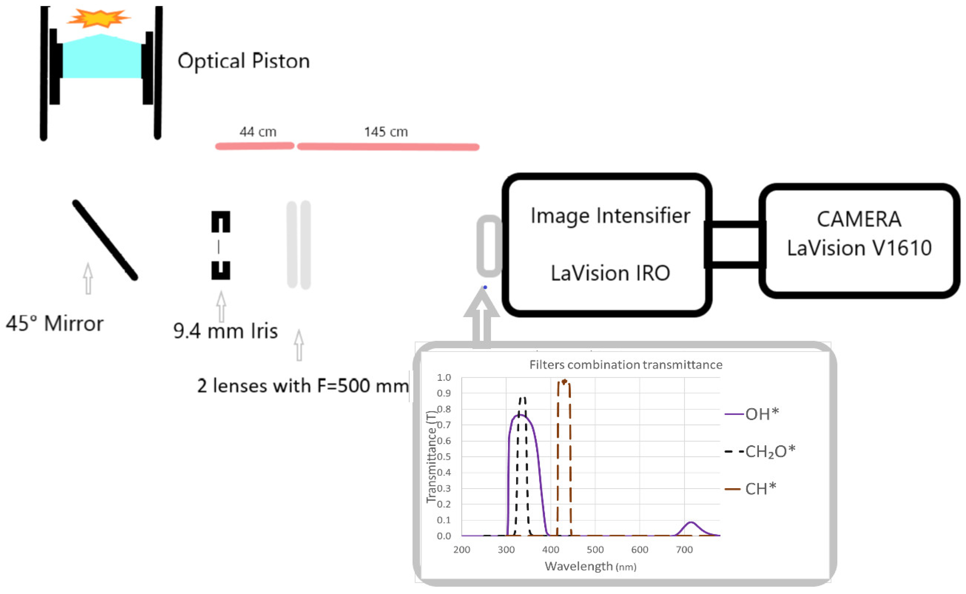
Chemiluminescence imaging was performed with a Phantom v1610 monochrome high-speed camera equipped with a Nikkor 105 mm objective and coupled to a high-speed image intensifier High-Speed IRO, from LaVision GmbH, Gottingen, Germany. As illustrated in Figure 2, the camera–intensifier assembly was positioned in line with a 45° mirror, and combustion luminosity was viewed through the extended piston and its fused-silica window, whose bowl geometry matches the original engine’s “Mexican hat” design. For OH* measurements, a FSQ-UG11 band-pass filter was combined with a 20CGA-305 long-pass filter (both provided by Micro-Controle Spectra-Physics, Beaune la Rolande, France) to favor transmission around 308 nm while suppressing out-of-band radiation. This OH* filter combination (330 ± 50 nm) does not block the contributions from other species, so in the IDT detection attention must be devoted to avoiding misinterpretations of the results. However, the small pilot injection and the substantial H2 fraction in the premixed charge allow us to assure that the main participant in the filtered signal is from the OH* chemiluminescence.
The resulting optical layout, including the spacing between iris, lenses, and imaging components, is provided in Figure 2. The intensifier settings were fixed at 61% gain with a 39.2 ms gate and a 5 ns delay, while the camera was operated at 16,000 fps with a 45 μs exposure time, yielding three frames per crank-angle degree (CAD). Each acquisition started at 10 CAD BTDC and recorded 150 images per cycle at 768 × 768 pixels2, corresponding to a magnification ratio of 11.5 pixels/mm. The high-speed image acquisitions were recorded for the 40 firing cycles.
The CH2O* and CH* chemiluminescence signals [37,38] were acquired through a Image Doubler (from LaVision GmbH, Gottingen, Germany). CH* emission was isolated using a Chroma Technology band-pass filter centered at 431 nm with a 28 nm bandwidth, whereas CH2O* (formaldehyde) chemiluminescence was captured using a stacked set of three bandpass filters (ZUL0325 LP, ZHS0385 SP, and ZUS0350 SP from Asahi Spectra USA, Inc., Torrance, CA, USA). It should be emphasized that the OH* filter combination does not fully reject CH2O* signal; however, because CH2O* chemiluminescence is typically orders of magnitude weaker than the OH* signal, its contribution is assumed negligible for the OH* measurements. For CH2O* and CH* imaging, the intensifier gain was raised to 69% while keeping the same gate and delay settings, and the objective was replaced with a custom lens providing adjustable focal length, resulting in 768 × 576 pixels2 images at 7 pixels/mm with the same exposure time. The combined-filter transmittance curves for each monitored radical are reported in Figure 2.

2.3. Imaging Post-Processing

Chemiluminescence data for OH*, CH*, and CH2O* were post-processed using an in-house MATLAB R2024a workflow:
  • First, a circular region-of-interest matching the piston-window diameter was applied to exclude parasitic light reflected by the piston crown and cylinder walls, so that only radiation transmitted through the quartz window was retained for analysis.
  • To reduce background noise, a background image was generated for each cycle by averaging three images acquired 3 crank-angle degrees (CADs) before the start of combustion. This background was subtracted from each individual image. The corrected images were then ensemble-averaged at each CAD over 40 cycles, and the corresponding mean pixel intensity was computed.
  • In addition, the ignition timing for each individual cycle was detected from a moving-median filter applied to a 10 × 10 pixel2 interrogation window: when the median intensity in this window exceeded twice the median value of the same window over the preceding four CADs and was also above the noise threshold (100 counts), the corresponding CAD was flagged as an ignition spot.
  • The ignition spot was then verified manually for each firing cycle to avoid misidentification. This was necessary for the CO2’s diluted composition variations, where the ignition CAD could be mistakenly spotted.

2.4. Methodology

To isolate compositional effects in the syngas/diesel dual-fuel configuration, the baseline H2/CO ratio of each reference syngas (Fluidbed, Updraft, and Downdraft) was preserved, while the N2 fraction was adjusted to compensate for the added CO2 and/or CH4. The resulting gas mixtures are listed in Table 3. The original syngas compositions of Bridgwater [6] are shaded in blue, green and red for Fluidbed, Updraft, and Downdraft respectively. This set of colors is kept in the figures presented in the following sections. Following the operating strategy established in a previous study [17] on a comparable metal engine, the premixed syngas/air equivalence ratio was fixed at 0.7 and the pilot quantity of the pilot fuel was reduced to the minimum level required for stable operation. Keeping the pilot injection as small as possible helps suppress soot incandescence contributions to the optical signal, which otherwise appear as localized bright spots in natural-luminosity imaging [27].

3. Results and Discussion

3.1. The Case of Decane Pilot Ignition by Itself

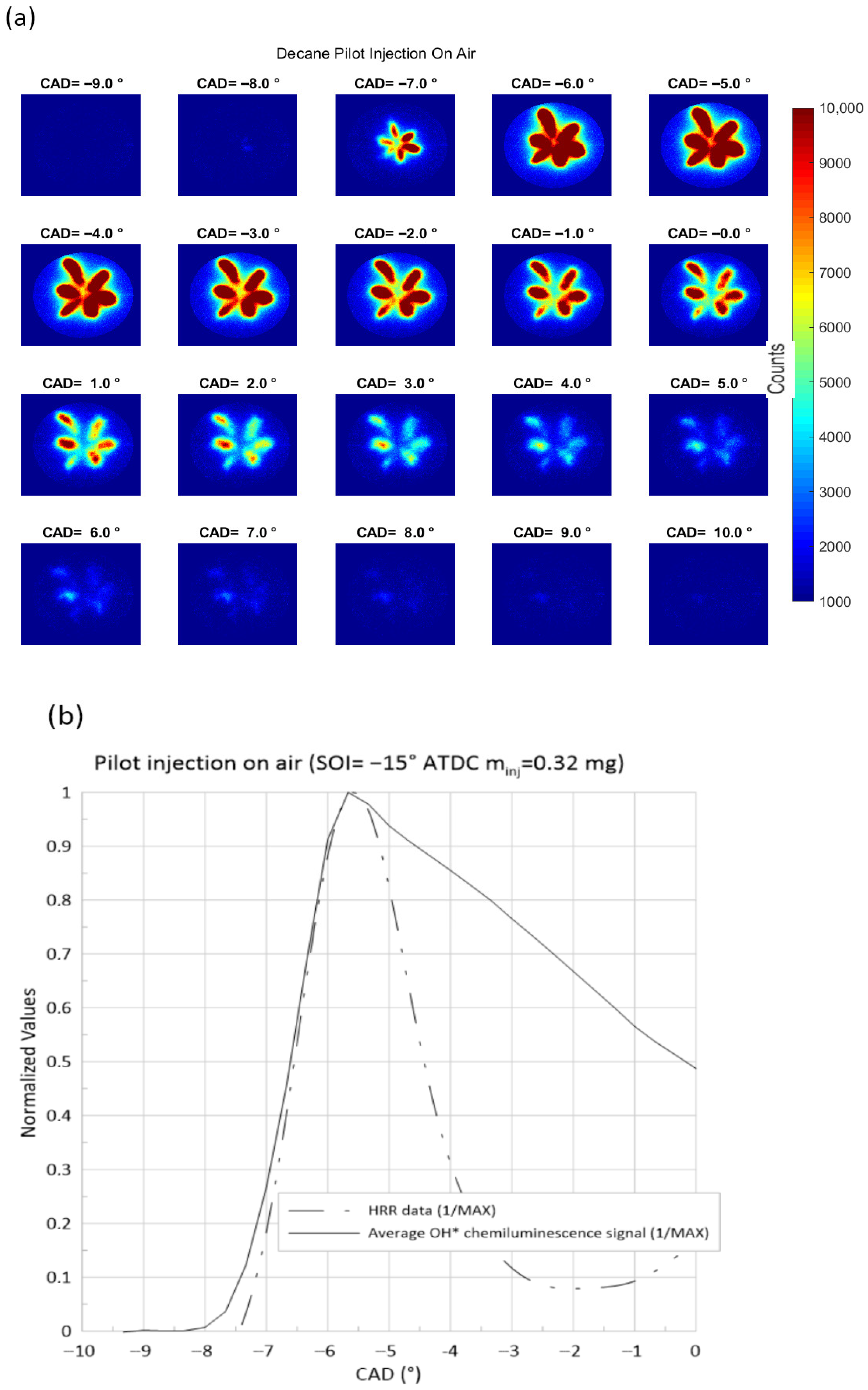
OH* images are first recorded with the engine operating on decane pilot injection only. As shown in Figure 3a, from around 8 CAD BTDC to 10 CAD ATDC, ignition develops along the six injector plumes, with noticeable differences among jets due to hole-to-hole irregularities. Because the injected decane mass is very small, the images reveal only six compact flame kernels rather than fully developed ones, without the bowl-filling flame as in conventional diesel operation. The maximum area of natural chemiluminescence strongly depends on the ignition location, which in this configuration follows the decane spray. The overall burn duration remains below 14 CAD.
Using these data, the spatially averaged OH* chemiluminescence signal is compared with the apparent HRR derived from the in-cylinder pressure (Figure 3b), and the two traces exhibit good qualitative agreement. However, the small pilot quantity also renders the pressure-based HRR estimate particularly noisy, resulting in a low signal-to-noise ratio. The ignition delay time (IDT), defined as the crank-angle interval between SOI and the OH* signal reaching 1% of its maximum, is approximately 7 CAD, which is consistent with the HRR-based estimate. As expected, OH* chemiluminescence persists after the HRR peak. The emission detected near 310 nm may arise either from OH* chemiluminescence or from the CO continuum [39] associated with CO-to-CO2 oxidation, and because these processes occur concurrently, the dominant contribution at 310 nm cannot be unambiguously identified.

3.2. Comparison of the Different Syngas Compositions

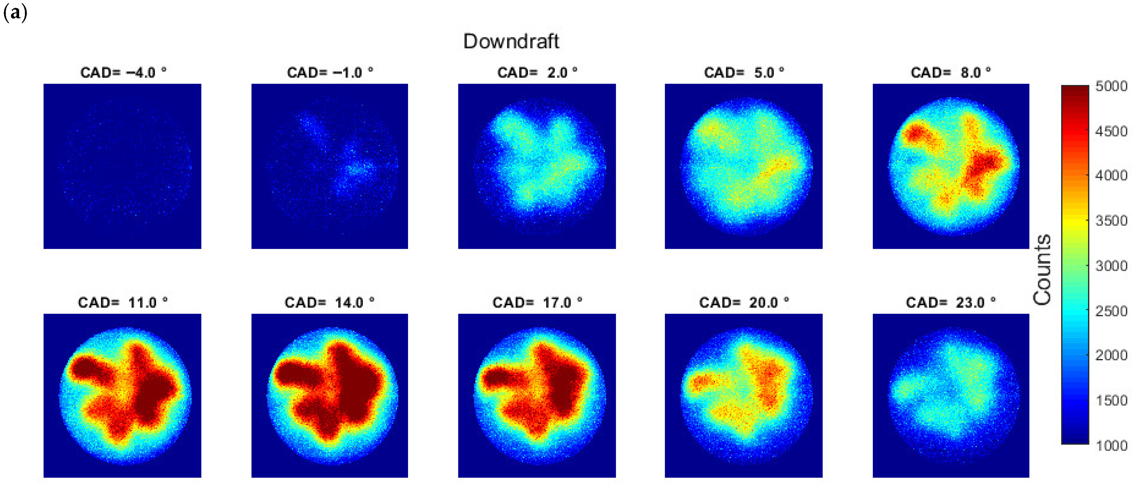
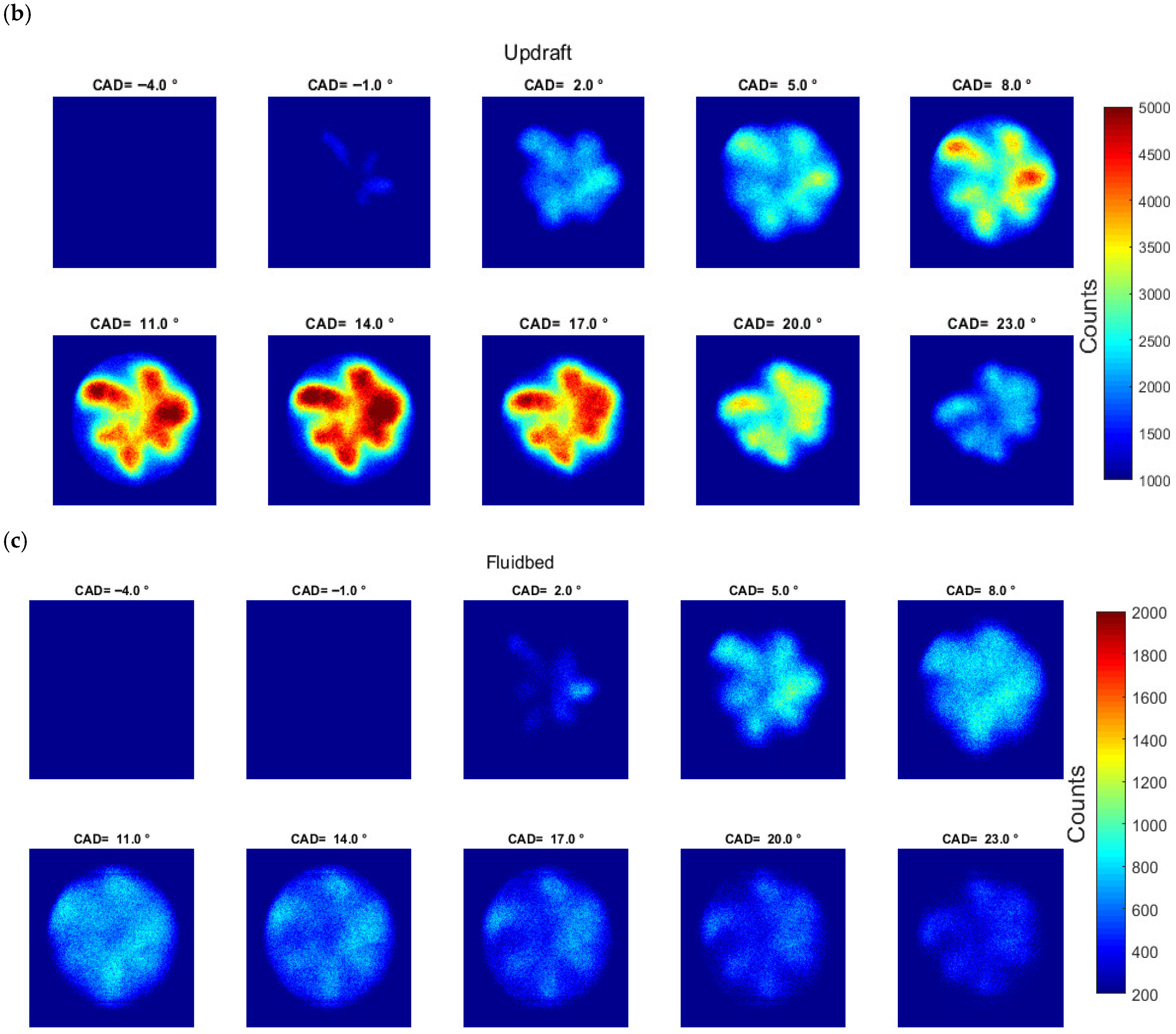
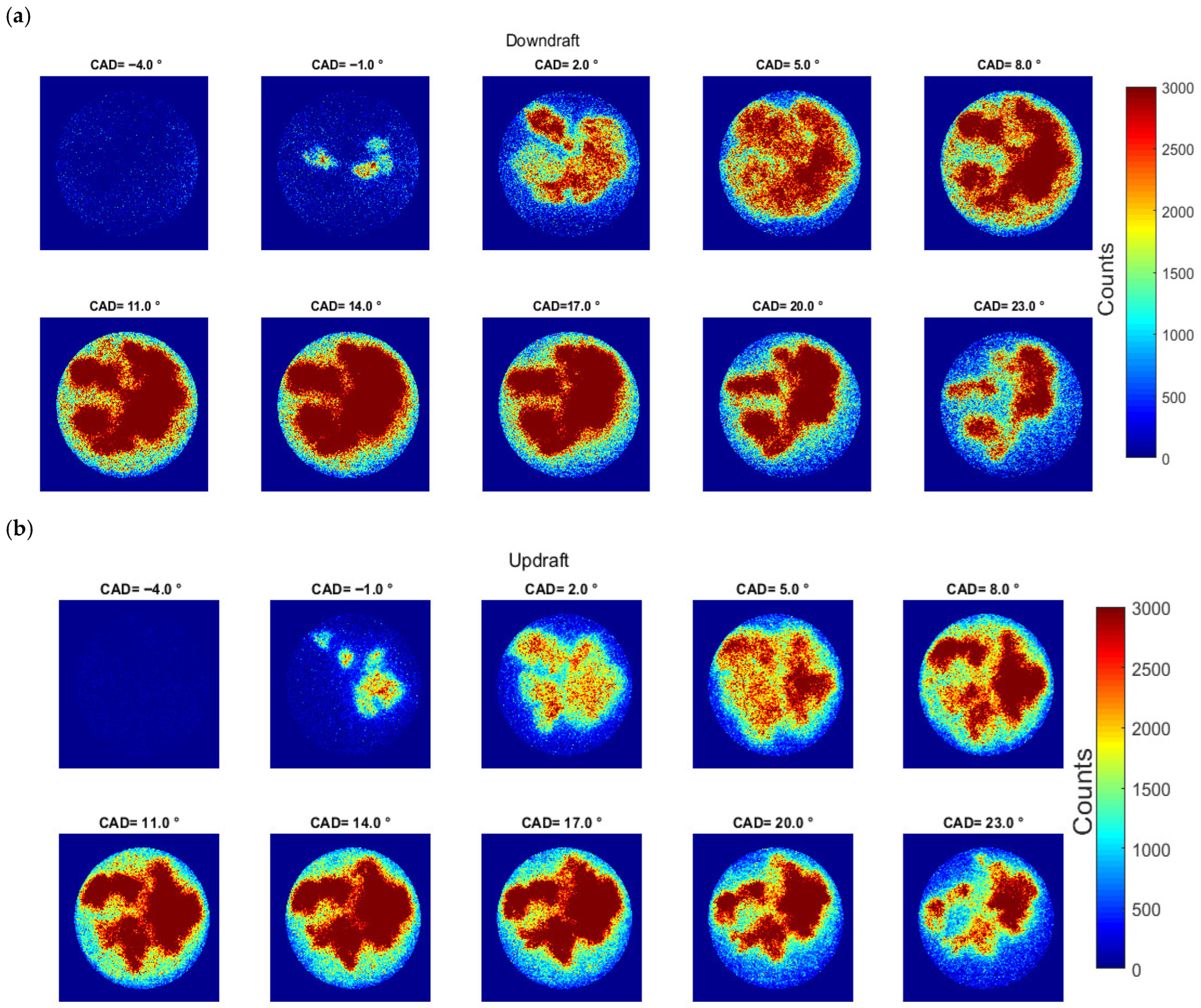
OH* chemiluminescence cycle-averaged images for the three syngas compositions are displayed in Figure 4. Downdraft and Updraft exhibit very similar combustion evolution and OH* intensity levels (Figure 4a,b): ignition still initiates along the decane spray, and even as the flame propagates further into the bowl volume, the characteristic multi-jet structure remains visible. Relative to operation with decane pilot injection only, the onset of OH* chemiluminescence shifts later by about 5 CAD for both Downdraft and Updraft, and by roughly 6 CAD for Fluidbed (Figure 4c). In addition, the Fluidbed case displays a lower OH* chemiluminescence level, which is consistent with two key compositional differences, namely the H2 fraction and the overall dilution provided by CO2 + N2.
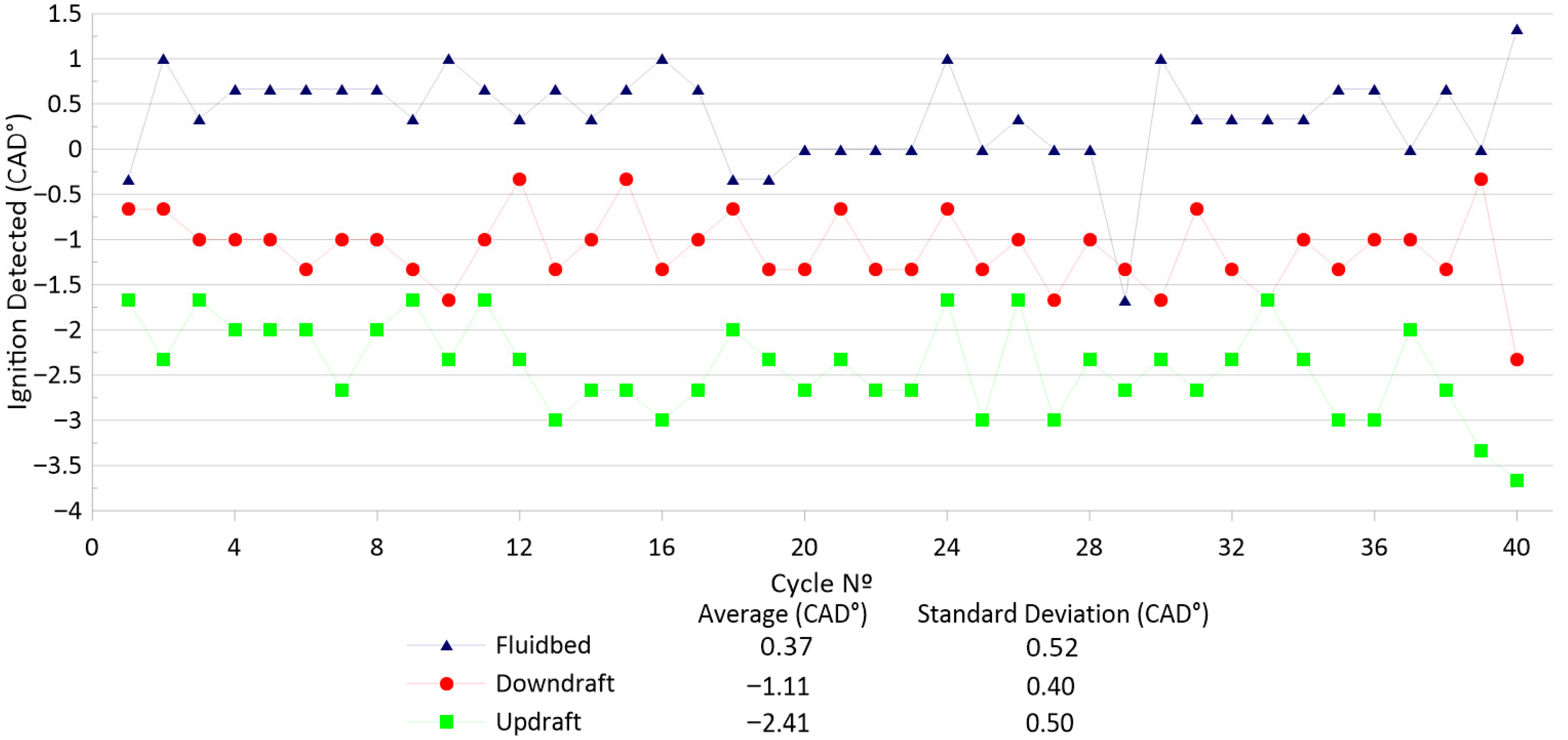
Cycle-to-cycle variations in IDT, based on the OH* onset, are presented in Figure 5 for each syngas composition, alongside its average and standard deviation in CAD. It is evident that the presence of CO2 is one key parameter for the ignition delay, as the Updraft composition, with the lowest amount of CO2 (9%), is the first to be ignited, followed by Downdraft and Fluidbed. The 20% CO2 share in the Fluidbed composition also influences the cycle-to-cycle variations with the largest value, whereas Downdraft and Updraft are much closer.
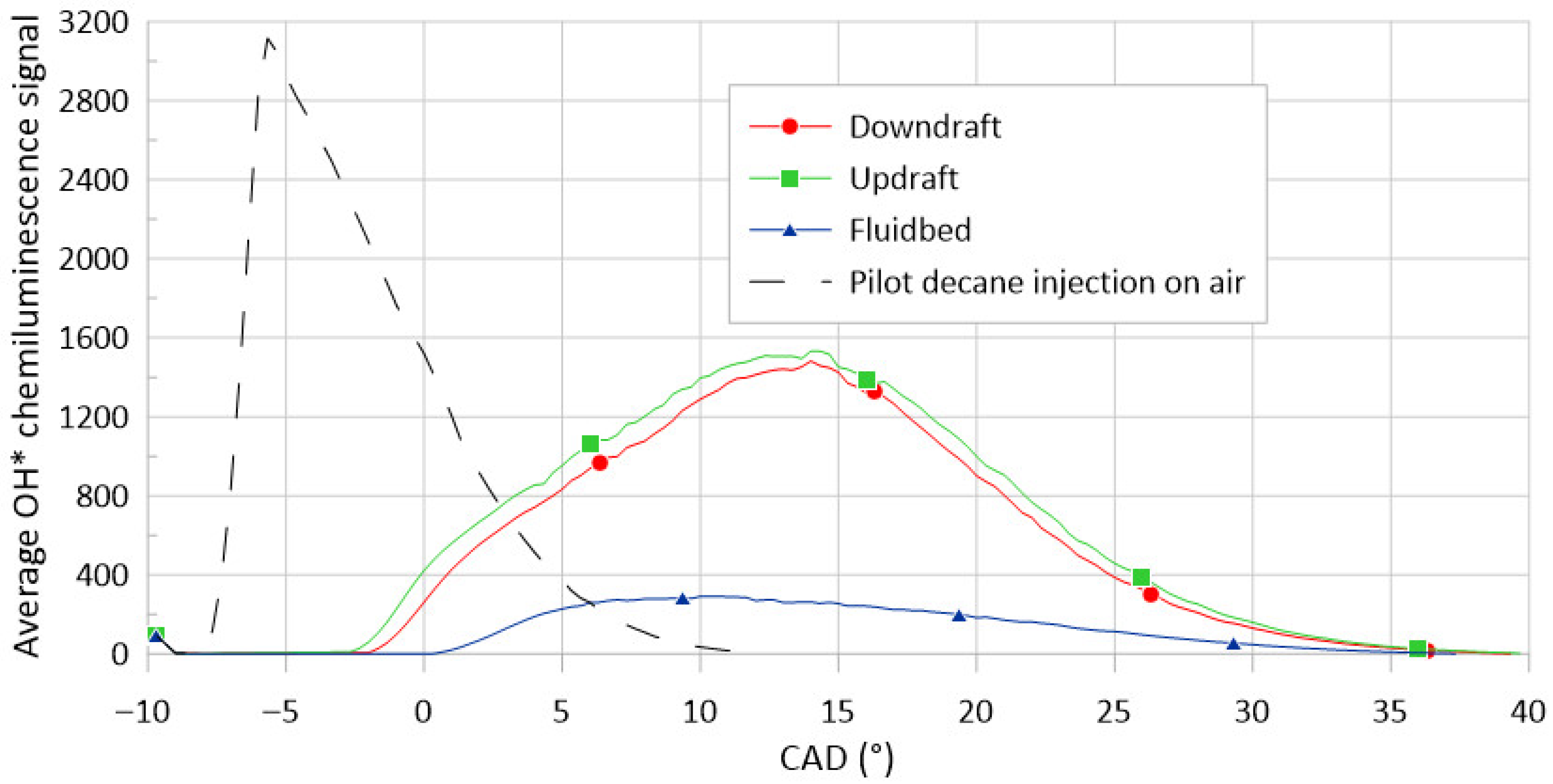
Figure 6 shows the evolution of the cycle averaged OH* chemiluminescence signal for the three syngas blends and for the decane pilot alone over the course of combustion. The presence of syngas increases the ignition delay time while reducing the overall OH* intensity. For the Fluidbed mixture, the OH* chemiluminescence level is roughly three times lower than the other two, primarily because of stronger dilution and its reduced H2 fraction. Interestingly, the OH* peaks earlier for Fluidbed than for the other two, which is counterintuitive given its lower laminar flame speed. The influence of the CO2 dilution will be discussed in the following sections.
Figure 7 provides instantaneous OH* chemiluminescence snapshots at several crank-angle positions within the same single engine cycle for each fuel composition, to emphasize the spatial features of the ignition process. As in the pilot ignition on air, without syngas in the charge, ignition does not occur simultaneously across the six decane sprays. Ignition generally initiates away from the jet tip, with the Fluidbed case constituting the main exception. Once OH* emission becomes sufficiently strong in localized regions at a given CAD, the signal progressively appears more spatially uniform throughout the chamber as the flame develops. Finally, these observations correspond to a single representative cycle, and since cycle-to-cycle variability is substantial, we cannot infer the IDT from Figure 7.
The spatially averaged OH* chemiluminescence (CL) intensity is compared with the ensemble-averaged apparent HRR in Figure 8. As expected, the Fluidbed mixture exhibits substantially weaker OH* signals, because of its higher CO2 concentration. In addition, the OH* intensity peak does not occur at the same crank angle as the apparent HRR peak, consistent with observations reported by Srna et al. [36] and Schlatter et al. [40] when they compared ignition delay times derived from conventional HRR analysis (or from Schlieren imaging) with those inferred from the onset of OH* chemiluminescence in NG/diesel dual-fuel experiments performed in rapid compression–expansion machines. For the Fluidbed case, the OH* trace is particularly affected because the signal remains weak under strong CO2 dilution (20% vol.), and its maximum appears earlier than the HRR peak. Similar behaviors were observed by Bihari et al. [41], whose OH* CL peaks were retarded with increasing EGR (dilution level) until the jump from 8% to 13.8%, where the luminosity value decreased but the peak temporal location (i.e., CAD) was, in fact, advanced.
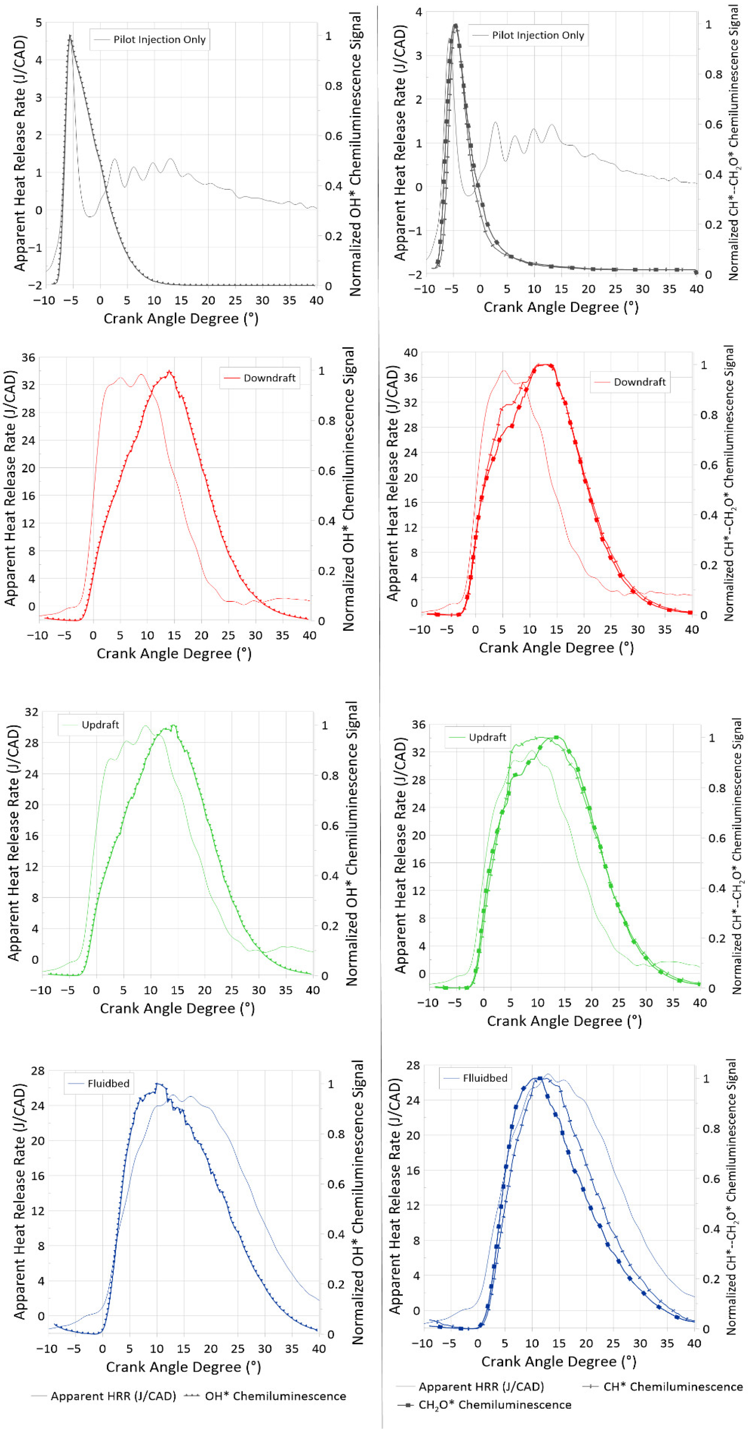
To assess whether other chemiluminescent radicals track the apparent HRR more closely in a syngas/diesel dual-fuel engine, the same comparison is performed for CH* and CH2O* signals, as shown in Figure 9. For all three syngas compositions, the cycle-averaged CH* and CH2O* intensities match the HRR profiles more closely than OH*, both in ignition timing and in the location of the peak, which is in agreement with the findings of Cheng et al. [37] for an NG/diesel dual-fuel engine. CH2O* chemiluminescence appears ahead of OH* and increases more rapidly. The lack of a clearly separate two-stage ignition, in either the HRR trace or the averaged chemiluminescence signals, is consistent with the very small pilot-fuel quantity, which shortens the induction period between the two stages [37]. The CH* signal emerges shortly after CH2O* but rises faster. For the Fluidbed mixture, the OH* and CH2O* peaks occur slightly before the HRR peak, whereas CH* remains better phased than the two other radicals. The differences in peak phasing of the compositions are due to the CO2 fraction of the Fluidbed composition, which quenches the radical emissions.

3.3. Effect of the CO2 and CH4 Content on the Syngas Ignition

Since syngas composition varies widely, in CH4 (a reactive component) and CO2 (a diluent) contents, it strongly influences ignition delay times (IDTs) and flame development in dual-fuel combustion. As an example, Rajasegar et al. [42] examined n-heptane ignition delays as a function of CH4 or H2 addition, combining experiments with kinetic simulations. They reported a marked inhibition of n-heptane autoignition chemistry in the presence of natural gas, manifested by longer ignition delays and a shift to first-stage ignition, which depends on the premixed equivalence ratio. This inhibition results from several coupled effects, including reduced oxygen availability due to premixing, changes in mixture heat capacity, and the role of CH4 as a radical sink.
Regarding CO2, changes in its concentration mainly modify the dilution level. Increasing CO2 also raises the mixture-specific heat by about 30%, which lowers the theoretical adiabatic flame temperature (Tad., in Table 3) and reduces the laminar flame speed. In addition to these thermal effects, CO2 also exerts important kinetic influences through third-body collisions and radical recombination pathways, which can slow chain-branching reactions and further suppress reactivity. The literature studies therefore indicate that CO2 dilution exerts a stronger influence than N2 dilution. In contrast, variations in CH4 content primarily alter the overall reactivity of the syngas. CH4 acts as an additional fuel component that can promote radical production and accelerate ignition, but it may also behave as a radical sink under some conditions by consuming OH* and other active radicals during its oxidation pathways. In the following subsections, the effect of the individual fractions of CO2 and CH4 on the syngas mixtures will be examined by following OH* chemiluminescence imaging and average signals.

3.3.1. The CO2 Concentration Effect

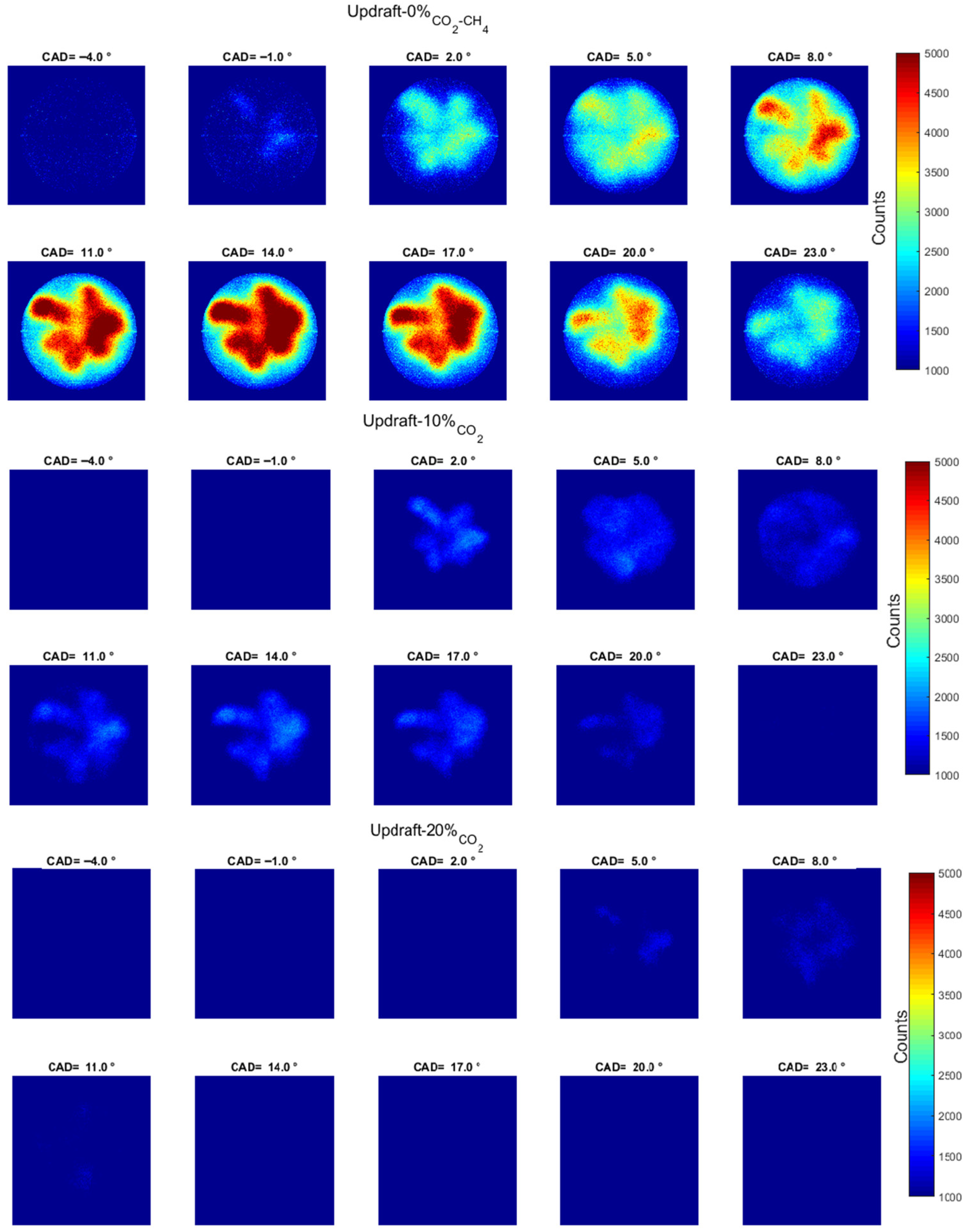
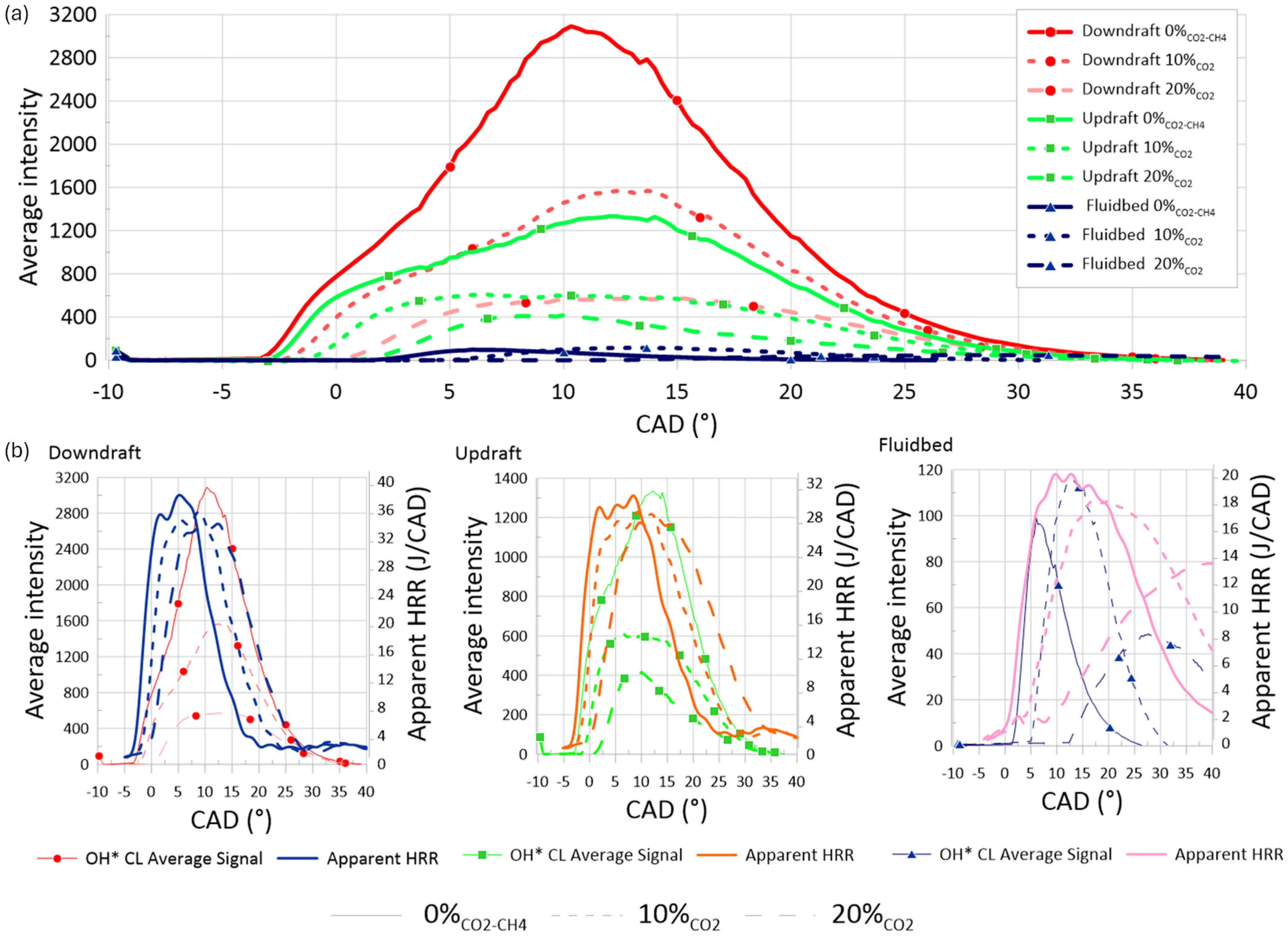
As an illustration of the CO2 effect, Figure 10 presents ensemble averaged OH* images for the Updraft composition only, since similar trends are observed for the other two. As the CO2 fraction in the total diluent mixture (CO2 + N2) increases, the combustion onset shifts noticeably later and the overall OH* intensity decreases substantially. At 20% CO2, the emission becomes very weak and is largely undetectable without rescaling the images. This is further illustrated by the average OH* chemiluminescence signals plotted in Figure 11, where the Downdraft composition, which normally yields the highest OH* intensity, is strongly affected by CO2 content. Replacing 10% of the fuel mixture of N2 with CO2 reduces the OH* CL signal to a level comparable to that of the Updraft case without CO2, albeit with a slightly longer ignition delay. The IDT difference between these two syngas compositions is therefore primarily attributable to the higher CO2 content of the Downdraft mixture.
Figure 11 presents the effect of CO2 on the raw average OH* chemiluminescence signal (a) and a comparison with the apparent HRR, grouped by base composition (b). It must be noted that the recorded images of the Fluidbed composition without CO2 or CH4 are noisy, so additional post-processing is required. Compositions with 10% CO2 yield a higher intensity, while the phasing of the OH* signal remains unchanged. The lower CO2 content of the Updraft composition accounts for the marginally longer IDT of the original Downdraft composition, as visible in Figure 8. Regarding the HRR on Figure 11b, we can see the presence of CO2 instead of N2 strongly delays and reduces (i.e., ‘flattens’) the apparent HRR, especially in the Fluidbed case where, as an example, the IDT is delayed by 4 CAD from 0 to 10% of CO2 and up to 8–9 CAD for 20% CO2.
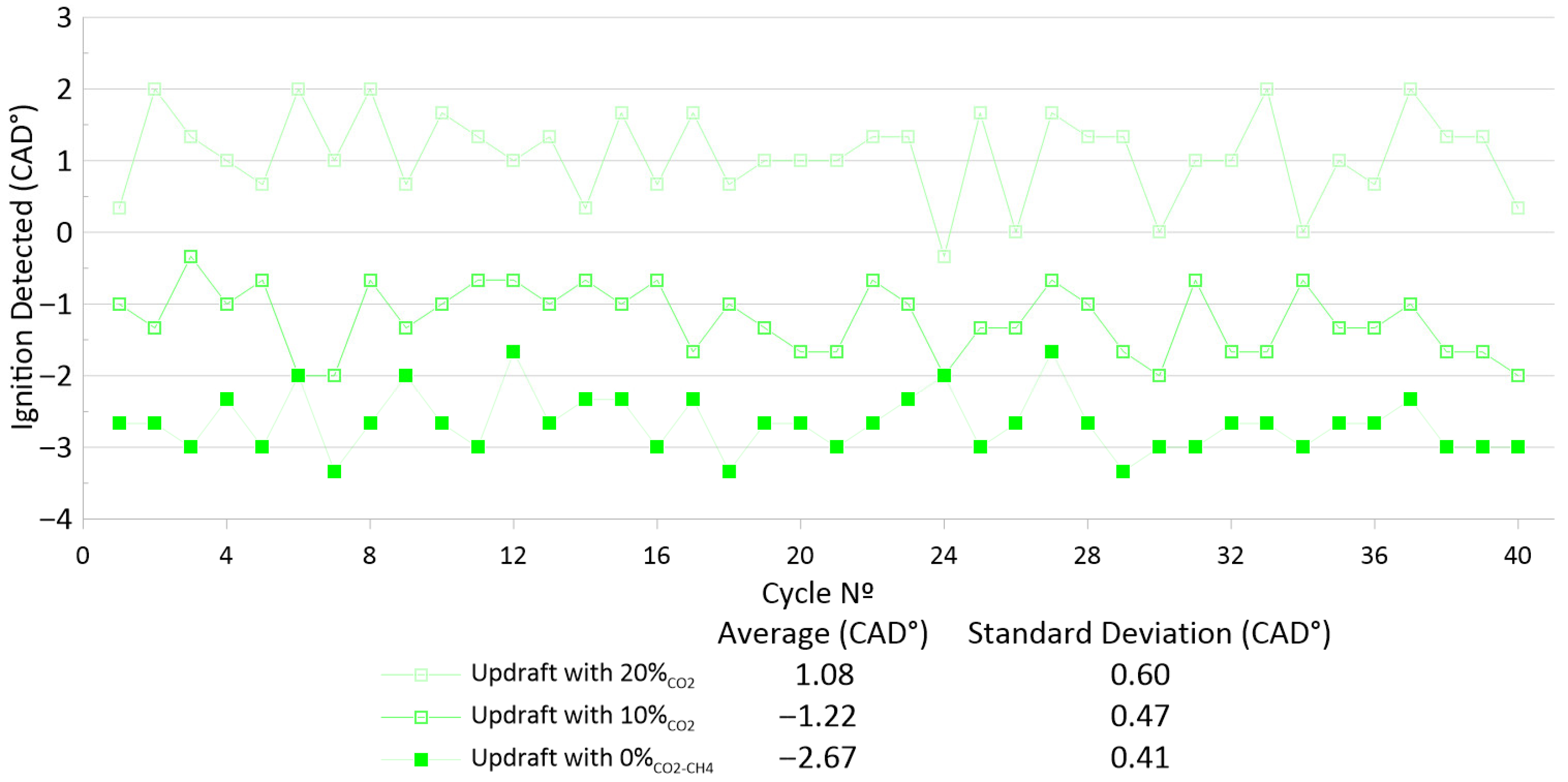
The same cycle-to-cycle variability analysis as in Figure 5 is performed, and the results are presented in Figure 12. Just as with the average ignition delay, CO2 dilution increases the cycle-to-cycle variability in the engine: the standard deviation of the ignition timing rises from 0.41 to 0.60 CAD when CO2 replaces 20% of the nitrogen content. This tendency is consistent with the findings of Gupta et al. [43], who demonstrated the same effect when analyzing the CO2 dilution ratio in biogas compositions.

3.3.2. The CH4 Concentration Effect

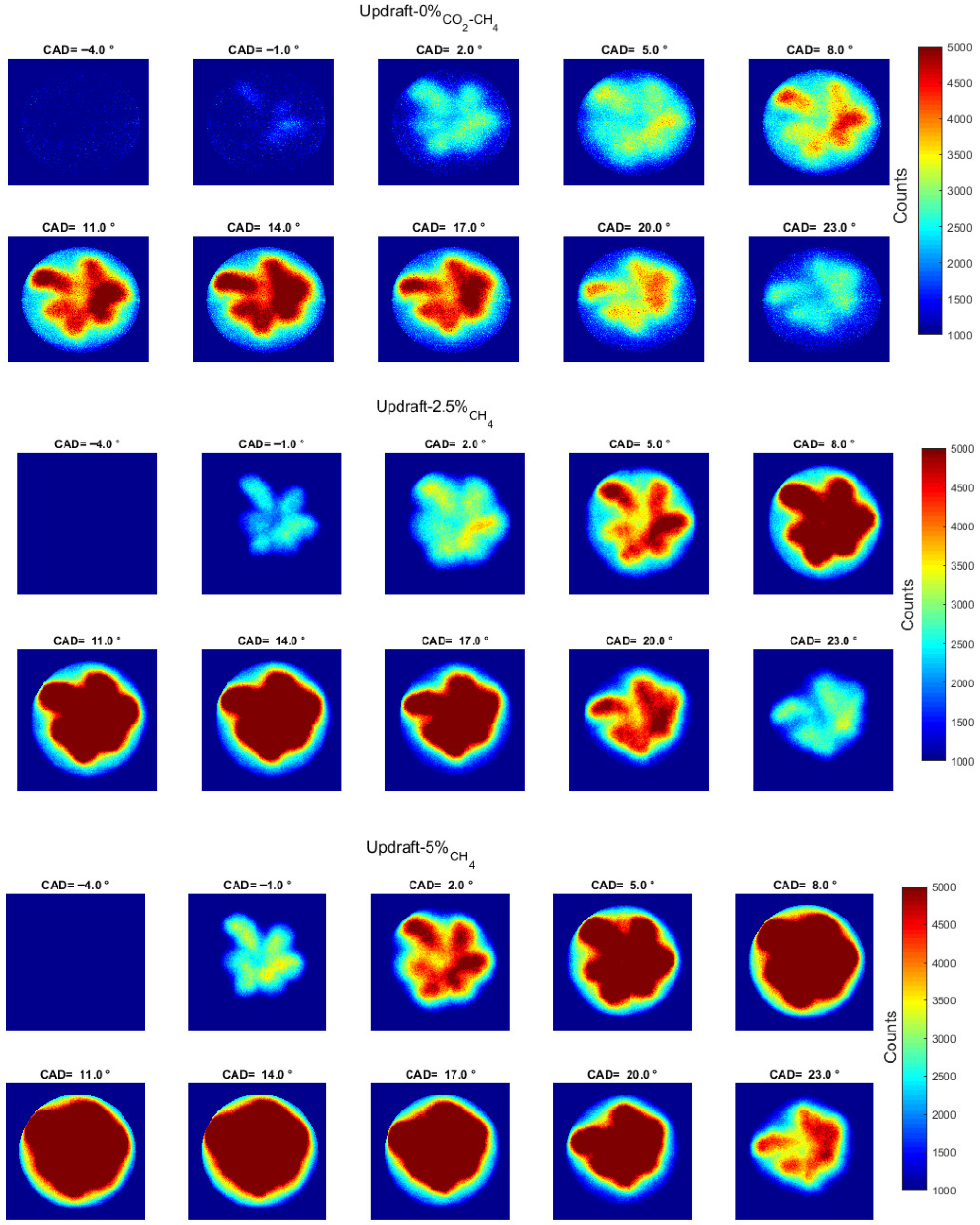
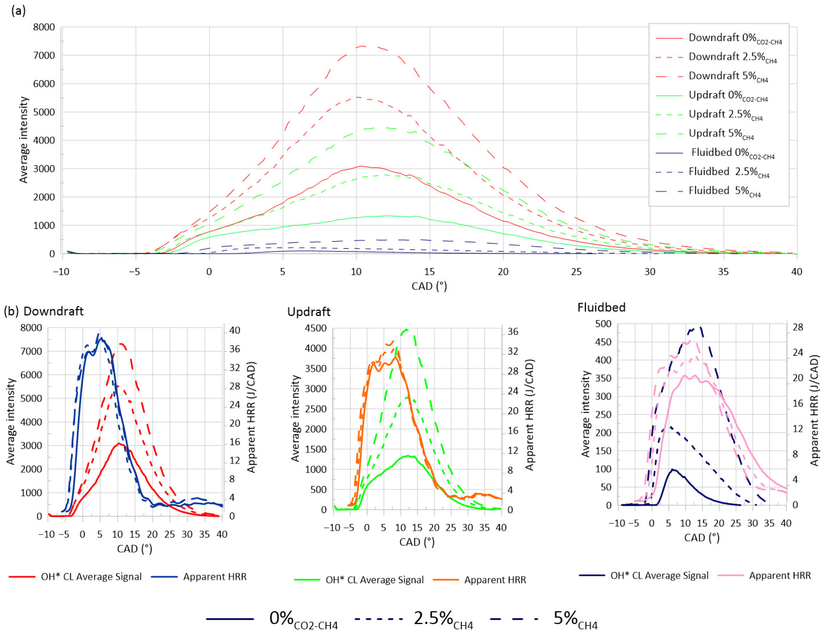
The effect of CH4 is also studied, but only at 2.5 and 5% vol. As shown in Figure 13, OH* is strongly enhanced by the presence of CH4 for Updraft, and similar trends were observed with the other two syngases. Figure 14, through the evolution of the average OH* chemiluminescence signal compared with the apparent HRR, shows how CH4 addition induces a better combustion phasing, most noticeably in the case of the Fluidbed composition.
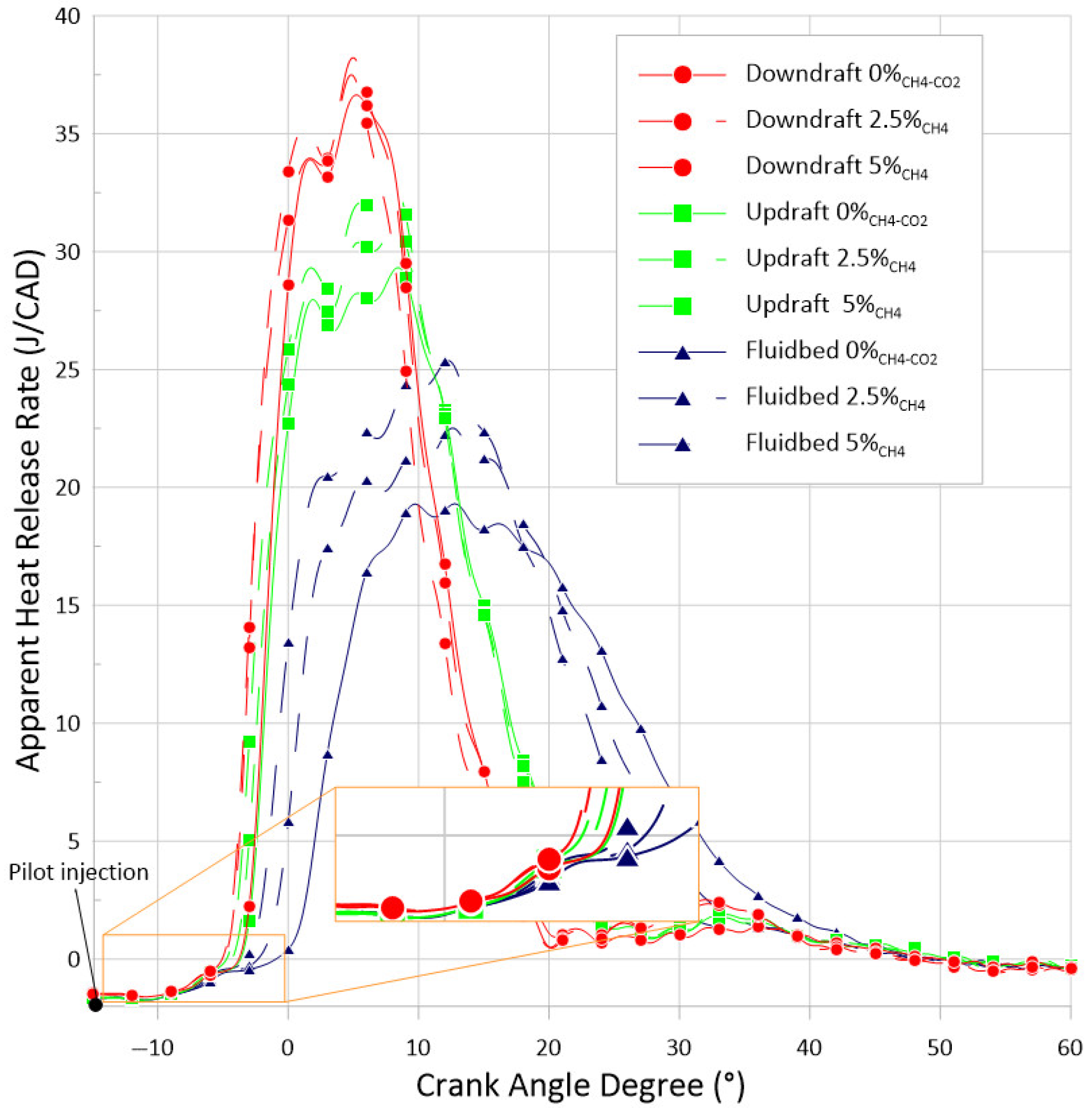
Figure 15 highlights that, as the CH4 concentration increases, combustion is slightly advanced, accompanied by a rise in the HRR peak. The ignition advance can be quantified using the CAD value at which the HRR reaches 1 J/CAD, referenced to the SOI: a 2.5% replacement of N2 with CH4 advances ignition by 0.4 CAD, while a 5% replacement advances it by 0.7 CAD.
The zoomed portion of the graph highlights the small first phase of the two-stage combustion, which results from the small pilot-fuel injection as discussed in [17]. Nevertheless, the HRR results from the optical engine make it easier to distinguish between the two combustion phases.
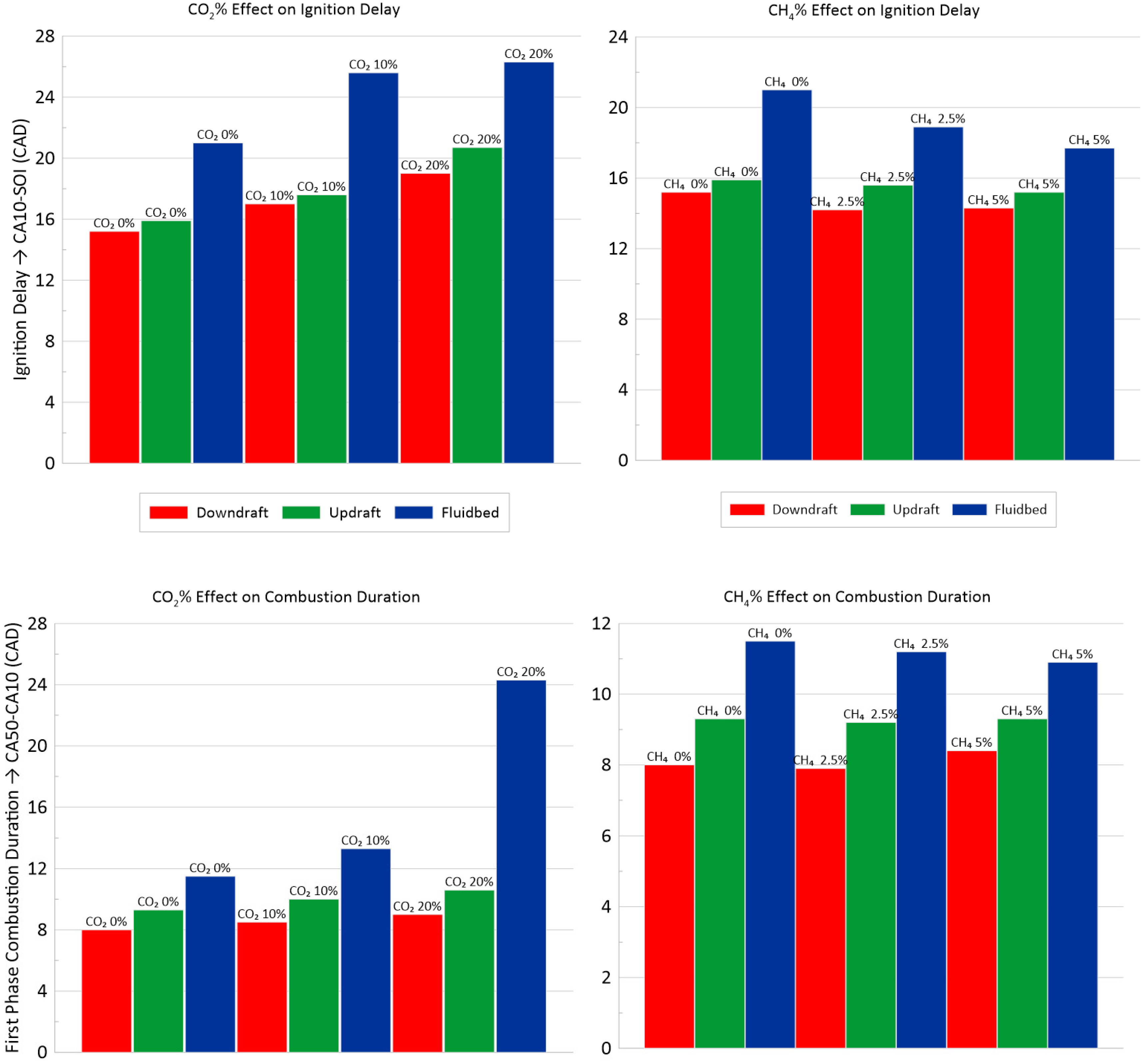
Figure 16 illustrates the influence of CO2 and CH4 concentration on the ignition delay, represented by the CA10–SOI crank-angle value, and on the first combustion phase (CA50–CA10). As expected, increasing CO2 content, which slows down the chemical kinetics, progressively delays ignition across all three syngas compositions. Conversely, CH4 addition slightly advances ignition, an effect that is especially notable for the original Fluidbed composition, where the reactive methane shares partially offset the inhibitory influence of CO2 and enhances the overall mixture reactivity.
The lower half of Figure 16 presents the duration of the first half of combustion (CA50–CA10) for the different syngas mixtures. The two additions behave differently for the Fluidbed-based composition compared to the other two: in the Fluidbed case, CO2 addition doubles the CA50–CA10 when 20% of the mixture is changed from N2 to CO2, a trend that is consistent with the predicted reduction in laminar flame speed (32.3 → 14.9 cm/s). These results confirm that while CO2 addition deteriorates combustion reactivity, moderate CH4 enrichment can mitigate ignition delays in dual-fuel syngas operation. For the Downdraft and Updraft compositions, however, the reduction in laminar flame speed—from 83 to 71.2 cm/s for Downdraft and from 61.5 to 58.2 cm/s for Updraft—does not translate into a longer combustion duration in the engine.

4. Conclusions

To improve the knowledge about the effect of pilot-fuel injection as a function of syngas composition, chemiluminescence of OH*, CH* and CH2O* images were compared to the heat-release rate in the case of the syngas/diesel dual-fuel combustion mode engine. Three syngas compositions, selected as representative of different gasification processes, are examined, and the effects of CO2 and CH4 content are investigated. The main conclusions are as follows:
  • Under the selected syngas/decane dual-fuel operating conditions, no soot incandescence is detected in the OH* and CH2O* chemiluminescence signals, which is attributed to the small, injected mass of decane. However, soot interference is noted in the CH* chemiluminescence images (i.e., at 431 nm), manifesting as a plateau in the corresponding average signal.
  • Updraft and Downdraft display comparable OH* behavior, with similar ignition delays and overall intensity levels. The Fluidbed blend behaves differently, showing an OH* intensity about three times lower and a longer ignition delay. Increasing CO2 dilution weakens the OH* maximum and, when a certain limit is reached, OH* chemiluminescence can peak earlier than the Heat-Release Ratio’s (HRR).
  • When the OH* average signal is compared with the apparent HRR, their peak timings do not coincide, indicating that OH* is not perfectly phased with the global heat-release evolution. The cycle-averaged CH* and CH2O* signals follow the HRR profile more closely, although they still do not fully resolve the very beginning of combustion development.
  • The impacts of CO2 dilution and CH4 enrichment are examined to rationalize the ignition delay trends measured in the engine. On the Fluidbed blend, the higher CH4 fraction counterbalances its larger CO2 share, leading to comparable ignition behavior despite the stronger dilution. In contrast, Updraft gas combines a higher CO content with a lower CO2 level, which can plausibly explain why its ignition delay remains close to that of the Downdraft mixture, in line with reports that variations in the H2/CO ratio have no major effect on ignition delay.
Future work could expand these findings by focusing on varying parameters that were kept fixed in this study, like the pilot-fuel injection parameters and the premixed charge syngas equivalence ratio, in an approach following the Design of Experiments (DoE) method. A dedicated sensitivity analysis of the ignition delay time (IDT) with respect to individual syngas components would be highly valuable. Such an analysis would quantify the relative contribution of each constituent to the overall ignition behavior. For instance, while the present study demonstrates that CO2 dilution exerts a stronger suppressive effect on ignition than N2 dilution, and that CH4 enrichment partially offsets this penalty, the precise sensitivity of IDTs to incremental changes in each component remains to be quantified under engine-relevant conditions. A response-surface or factorial DoE approach would enable such a decomposition while controlling for cross-coupling effects between composition variables. This would provide a more predictive framework for optimizing dual-fuel engine operation across the full range of syngas compositions produced in real biomass gasification systems.
These results, presented in this paper, constituted the final chapter of the first author’s PhD thesis manuscript [44].

Author Contributions

Conceptualization, R.R.d.C., P.B. and C.M.-R.; Methodology, R.R.d.C., P.B. and C.M.-R.; Validation, R.R.d.C., P.B. and C.M.-R.; Formal analysis, R.R.d.C., P.B. and C.M.-R.; Investigation, R.R.d.C.; Data curation, R.R.d.C.; Writing—original draft, R.R.d.C.; Writing—review and editing, R.R.d.C., P.B. and C.M.-R.; Supervision, C.M.-R.; Project administration, C.M.-R.; Funding acquisition, C.M.-R. All authors have read and agreed to the published version of the manuscript.

Funding

This work was supported by the LABEX CAPRYSSES (ANR-11-LABX-0006-01) of Université d’Orléans, within the program "Investissements d'Avenir" operated by the French National Research Agency (ANR) and the Région Centre-Val de Loire.

Data Availability Statement

The original contributions presented in this study are included in the article. Further inquiries can be directed to the corresponding author.

Conflicts of Interest

The authors declare no conflicts of interest.

Nomenclature

ϕ X/airEquivalence Ratio of fuel X in air
ϕ p r e m i x e d Premixed Equivalence Ratio of the charge
ATDCAfter top dead center
BTDCBefore top dead center
CAXXCrank angle where XX% of the heat was released
CADCrank angle degree
CH2O*Excited formaldehyde chemiluminescence
CH*Excited CH chemiluminescence
CLChemiluminescence
CNGCompressed natural gas
CO2Carbon dioxide
CRCompression ratio
CICompression ignition
EGRExhaust gas recirculation
GHGGreenhouse gas
HCCIHomogeneous charge compression ignition
HRRHeat-release rate
ICEInternal combustion engine
IDTIgnition delay time
IROHigh-speed image intensifier
LCALife cycle analysis
LHVLower heating value
LIF/PLIFLaser-induced fluorescence/planar laser-induced fluorescence
PinIntake Pressure
MSWMunicipal solid waste
NGNatural gas
OH*Excited OH radical chemiluminescence
O2Oxygen
RCMRapid compression machine
RPMRevolutions per minute
SISpark ignition
SOIStart of injection
Tad.Adiabatic flame temperature
TinIntake temperature
TDCTop dead center
THCTotal hydrocarbons

References

  1. Internacional Energy Agency. Net Zero Roadmap: Keep the 1.5 °C Goal A Global Pathway to in Reach; Internacional Energy Agency: Paris, France, 2023. [Google Scholar]
  2. Wu, H.; Hanna, M.A.; Jones, D.D. Life Cycle Assessment of Greenhouse Gas Emissions of Feedlot Manure Management Practices: Land Application versus Gasification. Biomass Bioenergy 2013, 54, 260–266. [Google Scholar] [CrossRef]
  3. Ardolino, F.; Arena, U. Biowaste-to-Biomethane: An LCA Study on Biogas and Syngas Roads. Waste Manag. 2019, 87, 441–453. [Google Scholar] [CrossRef]
  4. Dastjerdi, B.; Strezov, V.; Rajaeifar, M.A.; Kumar, R.; Behnia, M. A Systematic Review on Life Cycle Assessment of Different Waste to Energy Valorization Technologies. J. Clean. Prod. 2021, 290, 125747. [Google Scholar] [CrossRef]
  5. Schweitzer, D.; Gredinger, A.; Schmid, M.; Waizmann, G.; Beirow, M.; Spörl, R.; Scheffknecht, G. Steam Gasification of Wood Pellets, Sewage Sludge and Manure: Gasification Performance and Concentration of Impurities. Biomass Bioenergy 2018, 111, 308–319. [Google Scholar] [CrossRef]
  6. Bridgwater, A.V. The Technical and Economic Feasibility of Biomass Gasification for Power Generation. Fuel 1995, 74, 631–653. [Google Scholar] [CrossRef]
  7. Thomson, R.; Kwong, P.; Ahmad, E.; Nigam, K.D.P. Clean Syngas from Small Commercial Biomass Gasifiers; a Review of Gasifier Development, Recent Advances and Performance Evaluation. Int. J. Hydrogen Energy 2020, 45, 21087–21111. [Google Scholar] [CrossRef]
  8. Gasification Plant Databases|Netl.Doe.Gov. Available online: https://www.netl.doe.gov/research/coal/energy-systems/gasification/gasification-plant-databases (accessed on 27 May 2023).
  9. Rabello de Castro, R.; Brequigny, P.; Dufitumukiza, J.P.; Mounaïm-Rousselle, C. Laminar Flame Speed of Different Syngas Compositions for Varying Thermodynamic Conditions. Fuel 2021, 301, 121025. [Google Scholar] [CrossRef]
  10. Thi, L.D.; Zhang, Y.; Huang, Z. Shock Tube Study on Ignition Delay of Multi-Component Syngas Mixtures—Effect of Equivalence Ratio. Int. J. Hydrogen Energy 2014, 39, 6034–6043. [Google Scholar] [CrossRef]
  11. Paykani, A.; Chehrmonavari, H.; Tsolakis, A.; Alger, T.; Northrop, W.F.; Reitz, R.D. Synthesis Gas as a Fuel for Internal Combustion Engines in Transportation. Prog. Energy Combust. Sci. 2022, 90, 100995. [Google Scholar] [CrossRef]
  12. Sridhar, G.; Babu, R. Facts about Producer Gas Engine. In Paths to Sustainable Energy; IntechOpen: London, UK, 2010. [Google Scholar]
  13. Azimov, U.; Tomita, E.; Kawahara, N.; Harada, Y. Effect of Syngas Composition on Combustion and Exhaust Emission Characteristics in a Pilot-Ignited Dual-Fuel Engine Operated in PREMIER Combustion Mode. Int. J. Hydrogen Energy 2011, 36, 11985–11996. [Google Scholar] [CrossRef]
  14. Carlucci, A.P.; Ficarella, A.; Laforgia, D.; Strafella, L. Improvement of Dual-Fuel Biodiesel-Producer Gas Engine Performance Acting on Biodiesel Injection Parameters and Strategy. Fuel 2017, 209, 754–768. [Google Scholar] [CrossRef]
  15. Singh, P.; Kumar, R.; Sharma, S.; Kumar, S. Effect of Engine Parameters on the Performance of Dual-Fuel CI Engines with Producer Gas—A Review. Energy Fuels 2021, 35, 16377–16402. [Google Scholar] [CrossRef]
  16. Sharma, M.; Kaushal, R. Performance and Exhaust Emission Analysis of a Variable Compression Ratio (VCR) Dual Fuel CI Engine Fuelled with Producer Gas Generated from Pistachio Shells. Fuel 2021, 283, 118924. [Google Scholar] [CrossRef]
  17. Rabello de Castro, R.; Brequigny, P.; Mounaïm-Rousselle, C. A Multiparameter Investigation of Syngas/Diesel Dual-Fuel Engine Performance and Emissions with Various Syngas Compositions. Fuel 2022, 318, 123736. [Google Scholar] [CrossRef]
  18. Srna, A.; von Rotz, B.; Bolla, M.; Wright, Y.M.; Herrmann, K.; Boulouchos, K.; Bruneaux, G. Experimental Investigation of Pilot-Fuel Combustion in Dual-Fuel Engines, Part 2: Understanding the Underlying Mechanisms by Means of Optical Diagnostics. Fuel 2019, 255, 115766. [Google Scholar] [CrossRef]
  19. Zhao, H.; Ladommatos, N. Optical Diagnostics for Soot and Temperature Measurement in Diesel Engines. Prog. Energy Combust. Sci. 1998, 24, 221–255. [Google Scholar] [CrossRef]
  20. Gaydon, A.G. The Spectroscopy of Flames; Springer: Dordrecht, The Netherlands, 1974. [Google Scholar]
  21. Mancaruso, E.; Todino, M.; Vaglieco, B.M. Study on Dual Fuel Combustion in an Optical Research Engine by Infrared Diagnostics Varying Methane Quantity and Engine Speed. Appl. Therm. Eng. 2020, 178, 115623. [Google Scholar] [CrossRef]
  22. Augusta, R.; Foster, D.E.; Ghandhi, J.B.; Eng, J.; Najt, P.M. Chemiluminescence Measurements of Homogeneous Charge Compression Ignition (HCCI) Combustion. SAE Technical Paper, 3 April 2006; 2006-01-1520. [CrossRef]
  23. Srna, A.; Bruneaux, G.; von Rotz, B.; Bombach, R.; Herrmann, K.; Boulouchos, K. Optical Investigation of Sooting Propensity of N-Dodecane Pilot/Lean-Premixed Methane Dual-Fuel Combustion in a Rapid Compression-Expansion Machine. SAE Int. J. Engines 2018, 11, 1049–1068. [Google Scholar] [CrossRef]
  24. Huang, H.W.; Zhang, Y. Syngas Combustion Radiation Profiling through Spectrometry and DFCD Processing Techniques. Int. J. Hydrogen Energy 2012, 37, 5257–5267. [Google Scholar] [CrossRef]
  25. Srna, A.; von Rotz, B.; Herrmann, K.; Boulouchos, K.; Bruneaux, G. Experimental Investigation of Pilot-Fuel Combustion in Dual-Fuel Engines, Part 1: Thermodynamic Analysis of Combustion Phenomena. Fuel 2019, 255, 115642. [Google Scholar] [CrossRef]
  26. Dahms, R.N.; Paczko, G.A.; Skeen, S.A.; Pickett, L.M. Understanding the Ignition Mechanism of High-Pressure Spray Flames. Proc. Combust. Inst. 2017, 36, 2615–2623. [Google Scholar] [CrossRef]
  27. Ahmad, Z.; Aryal, J.; Ranta, O.; Kaario, O.; Vuorinen, V.; Larmi, M. An Optical Characterization of Dual-Fuel Combustion in a Heavy-Duty Diesel Engine. SAE Technical Paper, 3 April 2018; pp. 1–10, 2018-01-0252. [CrossRef]
  28. Ulishney, C.J.; Dumitrescu, C.E. Optical Investigation of Methane, Ethane, or Propane and Diesel at Low Load RCCI Conditions. Fuel 2023, 355, 129472. [Google Scholar] [CrossRef]
  29. Wüthrich, S.; Cartier, P.; Süess, P.; Schneider, B.; Obrecht, P.; Herrmann, K. Optical Investigation and Thermodynamic Analysis of Premixed Ammonia Dual-Fuel Combustion Initiated by Dodecane Pilot Fuel. Fuel Commun. 2022, 12, 100074. [Google Scholar] [CrossRef]
  30. Sun, W.; Zeng, W.; Guo, L.; Zhang, H.; Yan, Y.; Lin, S.; Zhu, G.; Jiang, M.; Yu, C.; Wu, F. An Optical Study of the Combustion and Flame Development of Ammonia-Diesel Dual-Fuel Engine Based on Flame Chemiluminescence. Fuel 2023, 349, 128507. [Google Scholar] [CrossRef]
  31. Solferini de Carvalho, F.; Peñaranda Mendoza, A.; Ribeiro dos Santos, L.; Henrique Rufino, C.; Malheiro de Oliveira, E.; Ferreira Silva, M.; Blanco Machin, E.; Travieso Pedroso, D.; Teixeira Lacava, P. Experimental Study of the Methane and Producer Gas Blends in an Optical Spark Ignition Engine: Combustion Characteristics, Thermodynamics and Emissions. Int. J. Engine Res. 2023, 24, 2708–2726. [Google Scholar] [CrossRef]
  32. Solferini de Carvalho, F.; Rufino, C.H.; Malheiro de Oliveira, E.; Mendoza, A.P.; Ribeiro dos Santos, L.; Machin, E.B.; Pedroso, D.T.; Lacava, P.T. Experimental Investigation of Hydrogen-Producer Gas Mixtures in an Optically Accessible SI Engine. Int. J. Hydrogen Energy 2024, 58, 500–513. [Google Scholar] [CrossRef]
  33. Shudo, T.; Nakajima, Y.; Tsuga, K. Combustion Characteristics of H2-CO-CO2 Mixture in an IC Engine. SAE Technical Paper, 5 March 2001; 2001-01-0252. [CrossRef]
  34. Shudo, T.; Nagano, T.; Robavashi, M. Combustion Characteristics of Waste-Pyrolysis Gases in an Internal Combustion Engine. Int. J. Automot. Technol. 2003, 4, 1–8. [Google Scholar]
  35. Martinez-Boggio, S.D.D.; Merola, S.S.S.; Teixeira Lacava, P.; Irimescu, A.; Curto-Risso, P.L. Effect of Fuel and Air Dilution on Syngas Combustion in an Optical SI Engine. Energies 2019, 12, 1566. [Google Scholar] [CrossRef]
  36. Srna, A.; Bombach, R.; Herrmann, K.; Bruneaux, G. Characterization of the Spectral Signature of Dual-Fuel Combustion Luminosity: Implications for Evaluation of Natural Luminosity Imaging. Appl. Phys. B Lasers Opt. 2019, 125, 1–16. [Google Scholar] [CrossRef]
  37. Cheng, Q.; Ahmad, Z.; Kaario, O.; Larmi, M. Simultaneous Visualization of Natural Luminosity and Chemiluminescence of Dual Fuel Combustion in an Optically Accessible Engine. SAE Technical Paper, 14 April 2020; 2020-01-0309. [CrossRef]
  38. Yu, X.; Zha, K.; Luo, X.; Taraza, D.; Jansons, M. Simulation and Experimental Measurement of CO2*, OH* and CH2O* Chemiluminescence from an Optical Diesel Engine Fueled with n-Heptane. SAE Technical Paper, 8 September 2013; 2013-24-0010. [CrossRef]
  39. Dubreuil, A.; Foucher, F.; Mounaïm-Rousselle, C. Analysis of Flame and OH* Natural Emissions of N-Heptane Combustion in a Homogeneous Charge Compression Ignition (HCCI) Engine: Effect of Burnt Gas Dilution. Energy Fuels 2009, 23, 1406–1411. [Google Scholar] [CrossRef]
  40. Schlatter, S.; Schneider, B.; Wright, Y.M.; Boulouchos, K. N-Heptane Micro Pilot Assisted Methane Combustion in a Rapid Compression Expansion Machine. Fuel 2016, 179, 339–352. [Google Scholar] [CrossRef]
  41. Bihari, B.; Gupta, S.B.; Biruduganti, M.; Sekar, R.R. Diagnostics for Combustion Metrics in Natural Gas Fuelled Reciprocating Engines. SAE Technical Paper, 19 January 2011; 2011-26-0007. [CrossRef]
  42. Rajasegar, R.; Srna, A.; Lee, T. Impact of Hydrogen on the Ignition and Combustion Behavior Diesel Sprays in a Dual Fuel, Diesel-Piloted, Premixed Hydrogen Engine. SAE Int. J. Adv. Curr. Prac. Mobil. 2024, 6, 1762–1776. [Google Scholar] [CrossRef]
  43. Gupta, S.K.; Mittal, M. Analysis of Cycle-To-Cycle Combustion Variations in a Spark-Ignition Engine Operating under Various Biogas Compositions. Energy Fuels 2019, 33, 12421–12430. [Google Scholar] [CrossRef]
  44. Rabello de Castro, R. Effect of the Fuel Composition of Syngas on the Combustion Process in Dual-Fuel Engine. Ph.D. Thesis, Université d’Orléans, Orléans, France, 2024. [Google Scholar]
Figure 1. Schematic view of the optical engine set-up.
Energies 19 02042 g001
Figure 2. Optical imaging set-up for OH* chemiluminescence.
Energies 19 02042 g002
Figure 3. OH* chemiluminescence images (a) and line-of-sight signal (b), averaged over 40 cycles for the pilot decane injection on air (without syngas)—N = 750 RPM, Pin = 1 bar, Tin = 25 °C (298 K).
Energies 19 02042 g003
Figure 4. OH* chemiluminescence 40 cycle-averaged images for the original syngas compositions in a dual-fuel engine ((a)—Downdraft, (b)—Updraft and (c)—Fluidbed)— ϕ p r e m i x e d = 0.7, N = 750 RPM, Pin = 1 bar, Tin = 25 °C (298 K).
Energies 19 02042 g004aEnergies 19 02042 g004b
Figure 5. Ignition detection for 40 combustion cycles for the three compositions— ϕ p r e m i x e d = 0.7, N = 750 RPM, Pin = 1 bar, Tin = 25 °C (298 K).
Energies 19 02042 g005
Figure 6. Average OH* chemiluminescence signal of the compositions.
Energies 19 02042 g006
Figure 7. Instantaneous OH* chemiluminescence along the same single combustion cycle for the 3 original compositions (ϕpremixed = 0.7, N = 750 RPM). (a) Downdraft (b) Updraft (c) Fluidbed.
Energies 19 02042 g007aEnergies 19 02042 g007b
Figure 8. Comparison between the apparent Heat-Release Ratio (HRR) and the OH* chemiluminescence signals for the 3 syngas compositions ( ϕ premixed = 0.7, N = 750 RPM).
Energies 19 02042 g008
Figure 9. Comparison of the average apparent HRR with the normalized average chemiluminescence signal of OH* (left) and CH*/CH2O* (right) ( ϕ premixed = 0.7, N = 750 RPM) for decane only and the three syngas compositions.
Energies 19 02042 g009
Figure 10. Effect of the CO2 share on OH* chemiluminescence averaged images over 40 firing cycles for Updraft-based compositions, ignited by the pilot injection ( ϕ s y n g a s / a i r = 0.7, N = 750 RPM).
Energies 19 02042 g010
Figure 11. (a) Effect of CO2 on the average OH* chemiluminescence signal; (b) comparison of the OH* average signal with the apparent heat-release rate (HRR), grouped by the original composition ( ϕ s y n g a s / a i r = 0.7, N = 750 RPM).
Energies 19 02042 g011
Figure 12. Effect of replacing N2 by CO2 on the ignition variability ( ϕ p r e m i x e d = 0.7, N = 750 RPM).
Energies 19 02042 g012
Figure 13. Effect of the CH4 share on the OH* chemiluminescence averaged images over 40 firing cycles for Updraft-based compositions ( ϕ s y n g a s / a i r = 0.7, N = 750 RPM).
Energies 19 02042 g013
Figure 14. (a) Effect of CH4 on the average OH* chemiluminescence signal; (b) comparison of the OH* average signal with the apparent heat-release rate (HRR), grouped by the original composition ( ϕ s y n g a s / a i r = 0.7, N = 750 RPM).
Energies 19 02042 g014
Figure 15. Effect of the CH4 addition on the apparent heat-release rate (HRR) of dual-fuel operation of the compositions ( ϕ s y n g a s / a i r = 0.7, N = 750 RPM).
Energies 19 02042 g015
Figure 16. Effect of CO2 (on the left) and CH4 (on the right) on the measured ignition delay times (IDTs) (on the top) and the duration of the first phase of combustion (on the bottom).
Energies 19 02042 g016
Table 1. Engine characteristics.
Displaced Volume:499 cm3
Bore:85 mm
Stroke:88 mm
Optical Window Diameter:50 mm
Rod Length:145 mm
Compression Ratio (CR):15.6:1 *
Swirl Ratio:2.0
Piston Bowl Type:“Mexican hat”
Firing TDC Position:0 CAD
Intake Valve Opening:351 CAD ATDC
Intake Valve Closure:157 CAD BTDC
Exhaust Valve Opening:140 CAD ATDC
Exhaust Valve Closure:366 CAD ATDC
Coolant Temperature:85 °C (358 K)
Oil Temperature:80 °C (353 K)
* Slightly lower CR than the standard engine.
Table 2. Mass-flow controllers.
Gas TypeControllerFull ScaleUncertainty
AIRBrooks 5853S500 NL/min±0.5%
N2Brooks 5851S100 NL/min±0.9%
COBrooks 5851S100 NL/min±0.9%
H2SLA585050 NL/min±1.0%
CO2SLA585037 NL/min±1.0%
CH4SLA58505 NL/min±1.0%
Table 3. Variations on the original syngas compositions. The original syngas compositions of Bridgwater [6] are shaded in blue, green and red for Fluidbed, Updraft, and Downdraft respectively. This set of colors is kept in the figures presented in the following sections.
VariationH2 (%vol)CO (%vol)CO2 (%vol)CH4 (%vol)N2 (%vol)Diluents-
CO2+N2
(%)
LHV (KJ/m3)Tad.
(K)
SU° (cm/s)
FB–0CO2-CH4914007777.02599186832.3
FB–10CO21006777.02599183424.3
FB–20CO22005777.02599180214.9
FB–2.5CH402.574.574.53448195533.0
FB–5CH4057272.04297201635.0
FB–REFERENCE2075070.04977200426.4
UD–0CO2-CH41124006565.04003209261.5
UD–10CO21005565.04003205951.1
UD–20CO22004565.04003202841.9
UD–2.5CH402.562.562.54852213159.5
UD–5CH4056060.05701216058.2
UD–REFERENCE935362.05022211251.1
DD–0CO2-CH41721006262.04257212083.0
DD–10CO21005262.04257208869.1
DD–20CO22004262.04257205757.9
DD–2.5CH402.559.559.55106215475.4
DD–5CH4055757.05955217871.2
DD–REFERENCE1314861.04597209562.7
Disclaimer/Publisher’s Note: The statements, opinions and data contained in all publications are solely those of the individual author(s) and contributor(s) and not of MDPI and/or the editor(s). MDPI and/or the editor(s) disclaim responsibility for any injury to people or property resulting from any ideas, methods, instructions or products referred to in the content.