Article

Friction-Aware Optimization of Manufacturable Balancing Cam Profiles for Passive Torque and Velocity Stabilization in Internal Combustion Engines


by
Daniel Silva Cardoso
1,2,
Paulo Oliveira Fael
1,2,
Hugo Lourenço
1,2 and
Pedro Dinis Gaspar
1,2,*
1
Department of Electromechanical Engineering, Faculty of Engineering, University of Beira Interior, 6201-001 Covilhã, Portugal
2
C-MAST—Center for Mechanical and Aerospace Science and Technologies, Calçada Fonte do Lameiro, 6201-001 Covilhã, Portugal
*
Author to whom correspondence should be addressed.
Energies 2026, 19(16), 3724; https://doi.org/10.3390/en19163724
Submission received: 12 July 2026 / Revised: 30 July 2026 / Accepted: 6 August 2026 / Published: 7 August 2026

Abstract

Torque and angular velocity fluctuations during idle and low-speed operation decrease drivetrain efficiency, increase vibration, and impose irregular loading on coupled systems such as hybrid powertrain generators and conventional transmissions. Building upon a previously validated balancing cam mechanism, this research presents a friction-aware redesign methodology that generates manufacturable cam profiles while preserving the torque characteristics necessary for effective compensation. Two target torque definitions are considered for cam synthesis: a smoothed profile derived from experimentally measured angular velocity and a cycle-resolved profile obtained from engine simulation. To account for friction effects, the selected target torque is reformulated to incorporate the parasitic torque introduced by the mechanism. Manufacturability constraints are then applied to ensure compatibility with the available cam-radius range and follower-stroke limit, while retaining regions of high compensation. The redesigned cam is subsequently implemented on a single-cylinder engine and evaluated through simulations and laboratory measurements. The assessment quantifies torque ripple and angular velocity fluctuation and evaluates the effect of incorporating estimated parasitic torque into cam-profile synthesis. Relative to the previously validated cam profile, the redesigned profile reduced angular-velocity standard deviation fluctuation by 50% and torque peak-to-peak by 44%. These improvements were achieved while maintaining manufacturable geometry and stable follower motion.

1. Introduction

1.1. Background

Internal combustion engines generate non-uniform torque due to the discrete nature of the combustion process and the cyclic operation of the slider–crank mechanism. This behavior is particularly evident during idle and low-speed operation, where the contribution of inertial smoothing is reduced, and the instantaneous torque variation has a stronger effect on crankshaft angular velocity. In single-cylinder engines, this problem is amplified because the entire operating cycle consists of only one power stroke, while intake, compression, and exhaust introduce negative or resistive torque [1,2,3,4,5].
Torque and angular velocity fluctuations affect engine regularity and increase vibration. They also impose cyclic mechanical loading on coupled systems. These effects appear not only in conventional transmissions, but also in hybrid powertrains, range extenders, and generator-based systems. Thus, irregular crankshaft motion may affect generator performance, noise, durability, and energy conversion stability [6,7,8]. Traditional solutions such as conventional flywheels, dual-mass flywheels, torsional dampers, or active torque control can reduce these fluctuations. However, they may increase system mass, complexity, packaging requirements, or energy dissipation [9,10].
Passive drivetrain devices include dual-mass flywheels, kinematically driven or variable-inertia flywheels, and torsional isolators, whereas active approaches apply counteracting torque through controlled actuators [11,12,13,14,15,16,17].
Passive mechanical approaches remain attractive when the objective is to improve rotational smoothness without adding electronic control, external energy input, or complex actuation. In this context, a balancing mechanism can be designed to store mechanical energy during high-torque regions of the engine cycle. In turn, it returns the stored energy during low-torque regions. This principle allows the compensation action to be synchronized [18,19].
Cam–spring mechanisms have also been used to compensate periodic torque in slider–crank systems and engine camshafts, demonstrating that a prescribed counter-torque can be generated directly from the mechanism geometry [20,21].

1.2. Previous Development of the Balancing Cam Mechanism

A previous study introduced a passive balancing cam mechanism intended to mitigate torque fluctuations in internal combustion engines during idle operation. That work established the system’s main operating principle: a cam profile designed from the target compensating torque, acting on a spring-loaded follower. The initial formulation decomposed engine torque into driving torque (produced by the combustion process), inertia torque (resulting from moving engine parts), and resistive torque (forces opposing movement). It also provided the mathematical basis for converting a required compensating torque into a cam profile [18].
The concept was later implemented and experimentally validated on a Honda® GX 120 single-cylinder engine. In that validation study, the mechanism was mounted outside the engine and powered by a transmission that rotated the balancing cam at half the crankshaft speed, meaning it completed one full cycle for every two crankshaft rotations, matching the 720° four-stroke cycle. The prototype included a spring-loaded roller follower and a specially shaped cam based on torque data collected from previous experiments. A variable reluctance sensor, which detects changes in magnetic fields to measure rotational speed, was used to monitor crankshaft angular velocity. The results showed that the mechanism reduced torque ripple and angular velocity fluctuations during idle operation, confirming the feasibility of using a passive balancing mechanism [19].
However, the validation study also revealed several limitations that motivate the present work. Specifically, the cam profile used in the prototype was generated from an experimentally obtained instantaneous torque curve that required smoothing before cam synthesis. This smoothing was necessary because the raw torque profile contained acquisition-induced irregularities and local high-frequency variations. These variations would have produced an impractical cam geometry, making the cam’s physical shape too complex or impossible to manufacture. While smoothing enabled a manufacturable cam, it also attenuated sharp torque features relevant to compensation. Furthermore, friction, follower inertia, and preload sensitivity were mainly analyzed after cam generation rather than as design inputs in the profile synthesis procedure.

1.3. Research Gap

Previous research demonstrated that a passive balancing cam mechanism can stabilize crankshaft behavior; however, it also revealed a central design compromise. The compensating torque profile must retain the primary characteristics of the engine torque demand, while the resulting cam profile must remain manufacturable and dynamically feasible. A profile that closely follows the required torque may result in excessive curvature, abrupt follower displacement, or high acceleration demands. In contrast, excessive smoothing may yield a feasible cam but diminish the compensation effect in the most dynamic regions of the engine cycle [19].
Beyond these limitations, the mechanism introduces parasitic effects that depend on factors such as spring preload, follower contact forces, bushing friction, and dynamic loading. Evaluating these effects only after cam design may result in a profile that fails to deliver the intended compensating torque in practice. Consequently, a more robust design strategy is necessary, incorporating friction and manufacturability constraints before generating the final cam profile.

1.4. Objectives and Contributions

The objective of this study is to develop and assess a friction-aware methodology for redesigning cam profiles for passive torque and angular-velocity stabilization in internal combustion engines. The work builds on a previously validated cam–spring mechanism but shifts the focus from concept validation to loss-aware profile synthesis and experimental performance assessment. The proposed framework may also be adapted to other cam-based mechanisms and profile configurations.
The first objective is to establish a suitable torque basis for cam synthesis by comparing two target profiles: a smoothed experimentally derived torque profile and a cycle-resolved simulated torque profile. This comparison determines which profile better preserves the torque features required for compensation while providing a suitable basis for profile generation.
The second objective is to reformulate the target compensating torque to account for parasitic effects introduced by the mechanism, including preload-dependent friction, follower contact friction, bushing and support friction, and dynamic loss effects. Accounting for these effects during synthesis is intended to produce a compensating torque that better approximates the effective torque required under operating conditions.
The third objective is to generate and assess a cam profile subject to explicit geometric and kinematic constraints, namely the admissible cam radius range and follower stroke limit. The redesigned profile is evaluated through simulation and experimental testing on a single-cylinder engine and compared with the previously validated cam. The simulation framework is also used to examine whether reduced angular-velocity fluctuation decreases angular acceleration, inertia torque, and the inertia-driven component of friction losses.

2. Materials and Methods

2.1. Reference Engine and Previously Validated Mechanism

The present study uses the same reference engine and experimental platform as those used in the previous validation stage of the balancing cam mechanism [19]. The reference engine is a Honda® GX120 single-cylinder, four-stroke, spark-ignition engine. This engine was selected for its simple architecture, mechanical adaptability, and pronounced cyclic torque irregularity, which make it suitable for assessing passive torque compensation strategies. The engine had previously been characterized through crank-angle-resolved simulations and laboratory measurements, providing the instantaneous torque and angular velocity profiles that served as the baseline for cam design and performance assessment [18,19].
The balancing mechanism considered in this work is a passive cam/spring mechanism that generates a counteracting torque synchronized with the engine cycle [18]. Its function is to store mechanical energy in a compression spring during regions of high engine torque and return that energy during regions of low or negative torque. In the validated prototype, the mechanism was mounted externally at the crankshaft output and driven through a 2:1 gear transmission, allowing the cam to complete one revolution over the 720° four-stroke cycle.
The previously validated mechanism consists of a cam mounted on the driven gear, a spring-loaded roller follower, and a support structure fixed to the engine [19]. The follower uses a 625-2RS bearing to maintain rolling contact with the cam profile and features a threaded adjustment system to control the spring preload. A nylon bushing is used at one of the support regions to reduce sliding friction between the follower and the structure. The support frame was manufactured from 3 mm steel plates and designed to accommodate various spring and cam configurations, enabling comparisons of alternative profiles and preload values [19].
The spring used in the validated mechanism was experimentally characterized before implementation. The measured stiffness was 24.2 kN/m, and the original cam was designed for a spring preload of 242 N [19]. The corresponding baseline cam parameters included an initial cam radius of 0.05 m, a roller radius of 0.008 m, and a crank-angle discretization of 10°. The previous cam profile was generated from an experimentally derived torque profile, which was smoothed with a 12-point moving average [19].
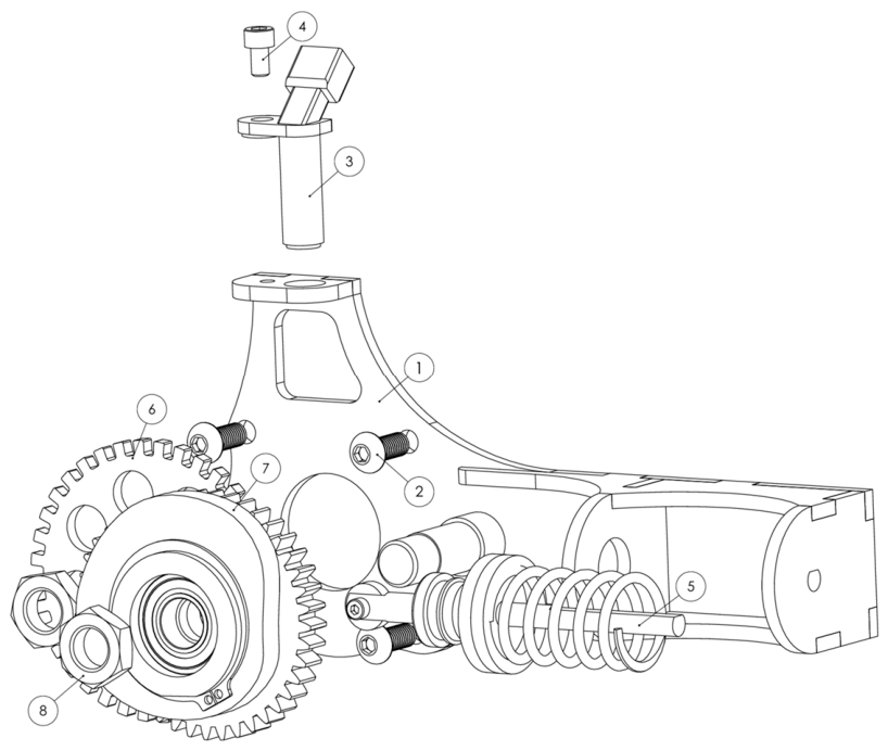
Previous experimental tests evaluated the mechanism under different operating configurations. First, the effect of the mechanism’s inertia was isolated by mounting the mechanism with the follower disengaged from the cam. This condition slightly reduced the angular velocity standard deviation, indicating that the added inertia had a small smoothing effect. Subsequent tests were performed with the mechanism engaged under three preload conditions: the design preload, a lower preload, and a higher preload. The design preload produced the best results because it provided sufficient compensating torque without the excessive contact forces, friction, and resistance observed at higher preload levels [19]. This mechanism, whose assembly is shown in the exploded view of Figure 1, provides the experimental baseline for the present study. However, the aim is not to revalidate the cam/spring concept, but to determine whether a friction-aware and manufacturability-constrained cam redesign can improve the relationship between the required compensating torque, the resulting cam geometry, and the effective torque delivered during operation.

2.2. Candidate Torque Profiles for Cam Synthesis

The balancing cam profile is generated from a target compensating torque that defines the energy exchange required during the engine cycle. Since this input determines the resulting cam geometry, follower motion, and effective compensating action, its selection is treated as the first step in the redesign procedure.

2.2.1. Experimentally Derived Smoothed Torque Profile

The experimentally derived profile was obtained from crankshaft angular velocity measurements at 1500 rpm over a complete 720° cycle. The angular velocity data were differentiated to calculate angular acceleration, and the corresponding instantaneous torque was reconstructed using the known equivalent rotational inertia of the engine and flywheel assembly [22,23].
Variable-reluctance sensors are widely used for instantaneous rotational-speed and torsional-vibration measurements, while crankshaft-speed fluctuations can also be used to reconstruct cycle-resolved torque profiles [24,25,26].
Before cam synthesis, the reconstructed torque profile was smoothed using the same 12-value moving average adopted in the previous prototype. This profile, therefore, represents the experimentally measured engine response while limiting the local oscillations that would otherwise lead to excessive cam curvature and abrupt follower motion. Its use in the present study provides continuity with the previously validated mechanism and establishes the experimental reference against which the simulated torque profile is compared.

2.2.2. Cycle-Resolved Simulated Torque Profile

The second candidate profile was obtained from the crank-angle-resolved engine simulation. The model calculates the instantaneous torque over the complete four-stroke cycle by combining the main driving, inertial, and resistive torque components, including cylinder pressure, reciprocating and rotating masses, valve-train effects, splash lubrication, and frictional interactions [27,28,29].
This profile provides a controlled representation of the engine cycle and avoids the local artefacts associated with experimental differentiation. For this reason, it is considered an alternative input for cam synthesis, particularly in regions where rapid torque transitions may compromise the direct use of reconstructed experimental data.
Since the simulated profile depends on the assumptions adopted in the engine model, it is evaluated against the experimentally derived smoothed profile rather than treated as a superior reference. The comparison focuses on the balance between compensation fidelity, cam manufacturability, and follower motion feasibility.

2.2.3. Comparison of Torque Profiles

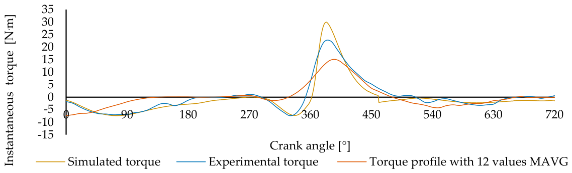
Figure 2 compares the torque profiles considered in the definition of the cam synthesis input over the complete 720° engine cycle. The figure includes the cycle-resolved simulated torque profile, the experimental torque profile, and the same experimental profile after applying a 12-value moving average.
The experimentally reconstructed profile matches the measured engine response, though it contains local oscillations associated with the angular velocity measurement and the numerical differentiation process. While these oscillations highlight the limitations of direct experimental torque reconstruction, the original profile is not used directly for cam synthesis, as this would produce abrupt cam radius variations and mechanically demanding follower motion.
The smoothed experimental profile reduces these local variations while preserving the main torque trend required for compensation. In contrast, the simulated profile provides a cycle-resolved representation of the engine torque demand, without acquisition-induced oscillations, but with characteristics that depend on the modelling assumptions. The comparison, therefore, supports selecting the input profile for cam synthesis by showing differences in amplitude, phase, and local torque transitions across the available torque representations.
To enable comparison, both simulated and experimental torque profiles were matched on a common 10° crank-angle grid by sampling the simulated data at the same positions as the experimental profiles, thus avoiding interpolation of experimental values.
For each candidate profile, we calculated the pointwise torque error relative to the original experimentally reconstructed torque as:
e i = T i T e x p
where T i represents either the sampled simulated torque profile or the smoothed experimental torque profile, and T e x p is the original experimentally reconstructed torque profile. The root-mean-square error was then calculated as:
R M S E = 1 n i = 1 n T i T e x p 2
To compare both profiles independently of the torque range, the error was normalized by the amplitude of the original experimentally reconstructed torque profile:
N R M S E = R M S E T e x p , m a x T e x p , m i n
where T e x p , m a x and T e x p , m i n are the maximum and minimum values of the original experimentally reconstructed torque profile, respectively. A lower NRMSE indicates closer agreement with the experimental reference.
The simulated profile presented an RMSE of 1.99 N·m and an NRMSE of 6.69% relative to the original experimentally reconstructed torque profile. In comparison, the 12-value moving-average profile presented an RMSE of 3.11 N·m and an NRMSE of 10.44%. Therefore, the simulated profile reduced the normalized error by approximately 36% relative to the smoothed experimental profile.
Based on this result, the simulated profile was selected as the basis for applying the additional compensation required to mitigate the frictional torque introduced by the mechanism. This profile provides a closer numerical representation of the original experimentally reconstructed torque while avoiding the local oscillations that would compromise cam manufacturability.

2.3. Friction-Aware Compensating Torque Profile Reformulation

The balancing cam mechanism is designed to generate a compensating torque that opposes the cyclic component of the engine torque. In an ideal loss-free system, the cam profile could be generated directly from the required compensating torque. However, the previously validated prototype showed that the torque produced by the cam/spring interaction is not fully transmitted to the crankshaft, because part of it is dissipated through follower contact friction, bushing/support friction, and dynamic effects associated with follower inertia. Therefore, in the present work, these effects are incorporated before cam profile generation, so that the redesigned profile is not based only on the engine torque demand but also on the parasitic torque introduced by the mechanism itself.
The required compensation torque is first obtained from the cyclic deviation of the instantaneous engine torque relative to its mean value. Considering the crank angle θ , the instantaneous engine torque is represented by T eng , and the mean engine torque over one complete cycle is represented by T ¯ eng . The fluctuating torque component to be compensated for is defined as:
T req = T eng T ¯ eng
The ideal compensating torque is then defined as the opposite of this cyclic component:
T comp = T req
where T c o m p represents the torque that the mechanism should effectively deliver to the engine to reduce torque ripple and angular velocity fluctuation. This formulation assumes that the mechanism behaves ideally, without internal losses. In the real mechanism, the effective torque delivered to the crankshaft is lower than the torque generated by the cam/spring system because of friction and inertial effects. Thus, the effective torque can be expressed as:
T eff = T cam T loss
where T c a m is the torque generated by the cam/spring interaction, T l o s s is the torque loss introduced by the mechanism, and T e f f is the torque effectively delivered to the engine. To make T e f f approach the required compensating torque, the target torque used for cam synthesis must include the expected loss contribution:
T cam , target = T comp + T loss
This sign convention assumes that T c o m p is the torque that must be effectively delivered to oppose the engine fluctuation. Therefore, the estimated loss torque is added to the target cam torque, so that after friction and dynamic losses, the remaining delivered torque is closer to the required compensation.
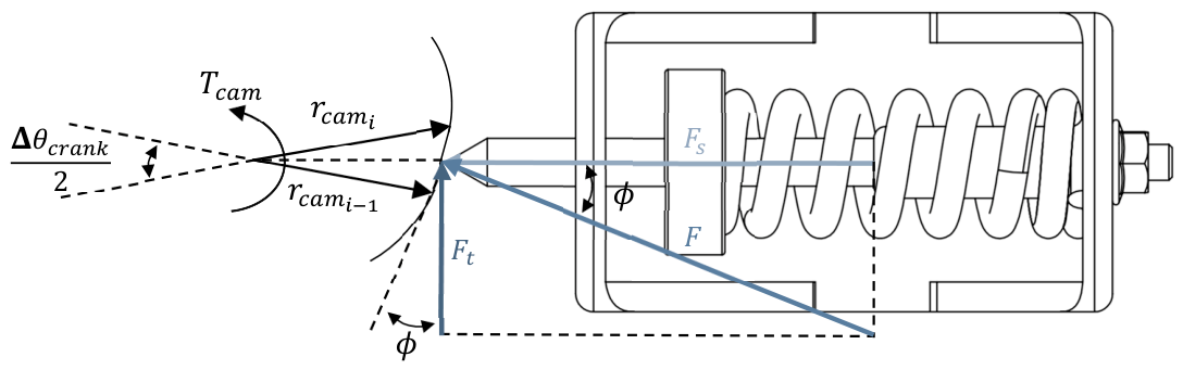
Figure 3 illustrates the dimensional and force relationships used to formulate the cam synthesis procedure. The diagram identifies the cam radius variation between consecutive crank-angle positions, the resulting cam torque, the spring force acting on the follower, and the tangential force component responsible for torque generation.
The main preload-dependent loss contribution is associated with the friction generated at the follower supports. The spring force acting on the follower is defined as:
F s = k [ r c a m r b a s e ] + P
where k is the spring stiffness, r c a m is the instantaneous cam radius, r b a s e is the base radius, and P is the spring preload. This expression shows that increasing preload increases the spring force even when the cam displacement is small. As a result, preload can improve torque generation in low-displacement regions, but it also increases support reactions and friction losses.
The tangential force transmitted between the cam and the follower is related to the spring force and to the local cam geometry:
F t = F s   t a n ϕ
where ϕ is the local angle that governs the conversion between spring force and tangential force.
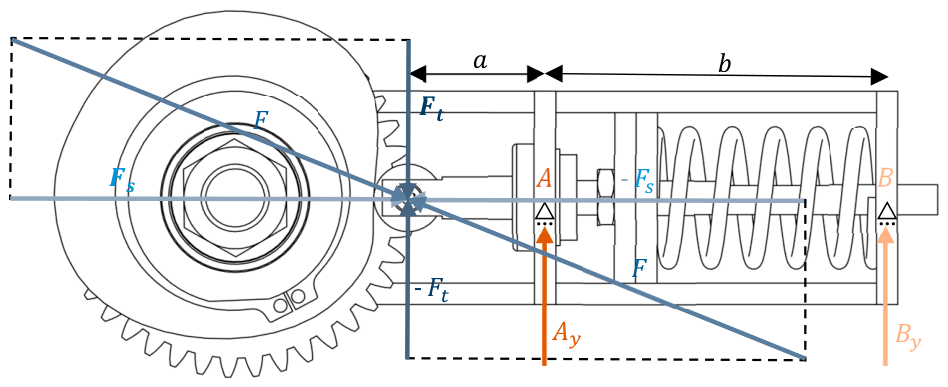
Figure 4 presents the mechanical model used to determine the support reactions generated by the tangential force F t . The follower is represented as a beam supported at two contact regions, A and B , separated by the distance b . The distance between support B and the roller center is defined as a , since it varies with the follower position and cam radius.
The vertical reactions at the supports are obtained from static equilibrium:
A y = F t   a + b b
B y = F t   a b
where A y and B y are signed support reactions defined according to the adopted y   a x i s convention. The negative value of B y indicates its direction and does not represent a negative normal load. Therefore, the Coulomb friction forces are calculated from the reaction magnitudes   A y and   B y , and act opposite to the instantaneous sliding direction of the follower:
F f , A = μ A   A y
F f , B = μ B     B y
where μ A and μ B are the friction coefficients at supports A and B , respectively. These friction forces oppose the follower motion and reduce the torque effectively transmitted by the mechanism. The corresponding support-friction torque-loss magnitude is expressed as:
T f , s u p = F f , A + F f , B   r e q
where r e q is the equivalent lever arm associated with the friction forces.
In addition to support friction, the follower assembly introduces an inertia-related contribution. As the cam rotates, the follower is accelerated and decelerated according to the imposed displacement profile. The follower inertia force is defined as:
F i n , f = m f a f
where m f is the effective moving mass of the follower assembly and a f is the follower linear acceleration. The corresponding torque contribution can be approximated as:
T i n , f = F i n , f   t a n ϕ   r c a m
This term becomes more relevant in regions where the cam profile imposes rapid follower motion. Therefore, abrupt radius changes and excessive curvature not only affect manufacturability; they also increase dynamic loading and may amplify the loss contribution of the mechanism.
The total loss torque considered in the friction-aware redesign is therefore expressed as:
T l o s s = T f , s u p + T i n , f
The main parameters used in the mechanical-loss model are summarized in Table 1. These parameters define the reference condition adopted for the friction-aware cam synthesis and provide the reference values for the subsequent sensitivity analysis.
Consequently, the corrected torque target used for cam synthesis becomes:
T c a m , t a r g e t = T c o m p + T f , s u p + T i n , f
In the previous validation stage, friction and inertia were mainly analysed after cam synthesis to explain the difference between the theoretical torque generated by the mechanism and the effective torque delivered during operation. In the present work, these effects are introduced before cam profile generation. The redesigned cam is therefore generated from a target torque that already accounts for the parasitic torque expected from the mechanism.
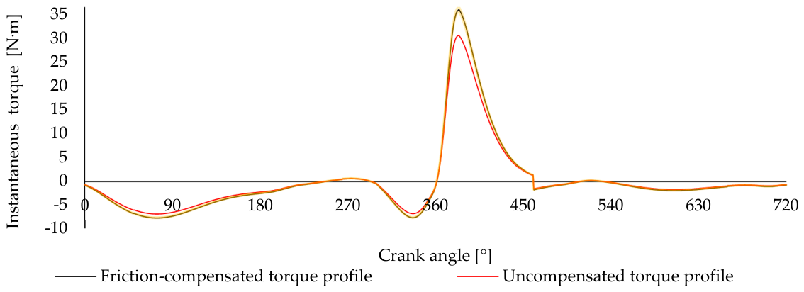
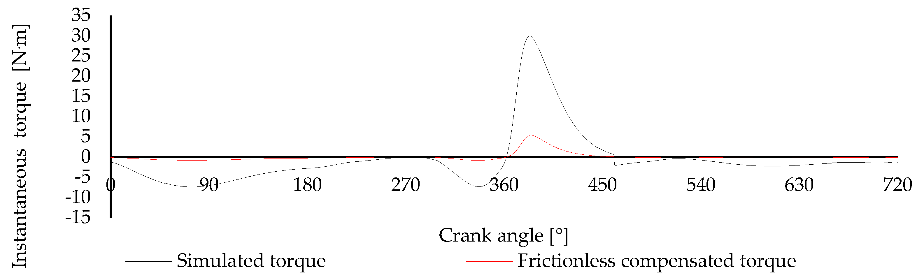
Figure 5 presents the simulated torque profile obtained using the proposed methodology, including the parasitic torque generated by the mechanism. To assess the sensitivity of the simulated torque profile to variations in the model inputs, a uniform ±10% variation was applied simultaneously to the nominal loss-model parameters while maintaining the nominal cam geometry. The yellow shaded band around the friction-compensated torque profile represents the resulting range. The maximum total width of the sensitivity band is 1.09 N·m, occurring at a crank angle of approximately 380°. The relatively narrow sensitivity band indicates that the predicted torque profile is not substantially affected by the combined ±10% variation in the selected model parameters.

2.4. Cam Profile Generation and Manufacturability Constraints

The cam profile is generated from the friction-aware target torque defined in Section 2.3. The purpose of this step is to convert the required compensating torque into a physical cam geometry capable of imposing the corresponding spring displacement over one complete engine cycle. Therefore, the cam profile must reproduce the compensation sequence associated with intake, compression, expansion, and exhaust phases.
The balancing mechanism transforms the radial displacement imposed by the cam into spring compression. The resulting spring force is then converted into a tangential force at the cam/follower contact, generating a torque on the camshaft.
The torque generated by the cam/spring interaction is then:
T c a m = F t   r c a m
Substituting the previous expressions gives:
T c a m = k ( r c a m r b a s e ) + P t a n ϕ   r c a m
For cam synthesis, the desired torque is the corrected target torque T c a m , t a r g e t , previously defined by including the required compensating torque and the estimated mechanical loss contribution. Therefore, the local geometric term can be obtained from:
t a n ϕ = T c a m , t a r g e t r c a m k ( r c a m r b a s e ) + P
The cam radius is then calculated iteratively as a function of crank angle. Considering two consecutive angular positions, the new cam radius is estimated from the previous radius and the local value of tan ϕ :
r c a m , i = r c a m , i 1 +   Δ θ c r a n k 2   r c a m , i 1 tan ϕ i
where r c a m , i is the cam radius at the current angular step, r c a m , i 1 is the radius at the previous step, and Δ θ c r a n k is the crank-angle increment.
After determining the radial profile, the cam geometry is represented in Cartesian coordinates to define the manufacturable profile. The polar-to-Cartesian conversion is given by:
x i = r c a m i c o s θ c r a n k i 2
y i = r c a m , i s i n θ c r a n k i 2
where x i and y i are the Cartesian coordinates of the theoretical cam profile at each angular position.
The cam profile was initially generated as a pitch curve for an ideal point follower. Since the physical mechanism uses a roller follower, this pitch curve was subsequently geometrically adapted to the prescribed roller radius. The roller radius was therefore not an optimization variable during the initial profile synthesis. The final roller-corrected cam coordinates are obtained from:
x r i = x i r r o l l e r c o s θ c r a n k i 2 ϕ i
y r i = y i r r o l l e r s i n θ c r a n k i 2 ϕ i
where r r o l l e r is the roller radius, and x r i and y r i define the final cam profile in contact with the roller follower.
Once the friction-aware target torque is converted into a radial cam profile and subsequently into roller-corrected coordinates, the resulting geometry represents the theoretical cam shape required to impose the desired spring force variation. However, this theoretical solution must be assessed against the physical limits of the existing mechanism, since a torque-matched profile may still lead to excessive radial growth, insufficient base radius, or follower motion incompatible with the available stroke. For this reason, the generated profile is treated as a preliminary solution and is subjected to geometric and displacement constraints before being retained for implementation.
These constraints are applied at this stage to verify whether the resulting geometry can be manufactured, assembled, and operated within the physical limits of the cam–follower–spring mechanism. The objective is not to remove all local torque variations, since some of these variations are relevant for compensation. Instead, the objective is to preserve the main compensating regions while excluding cam profiles that would require impractical dimensions or excessive follower motion.
The first constraint defines the admissible cam radius. The cam radius must remain within the minimum and maximum values imposed by the mechanism layout, structural requirements, and available packaging space:
r m i n r c a m r m a x
where r m i n   prevents undercutting, excessive local weakening, or contact conditions that would compromise the roller/cam interaction, while r m a x ensures that the cam remains compatible with the available follower displacement.
The second constraint limits the follower displacement. Since the mechanism uses a spring-loaded follower, the cam-induced displacement must remain within the available stroke of the support structure and spring assembly:
0 s s m a x
where s = r c a m r b a s e is the follower displacement and s m a x is the maximum admissible displacement. This constraint prevents excessive spring compression and avoids operating the spring or follower close to mechanical limits.
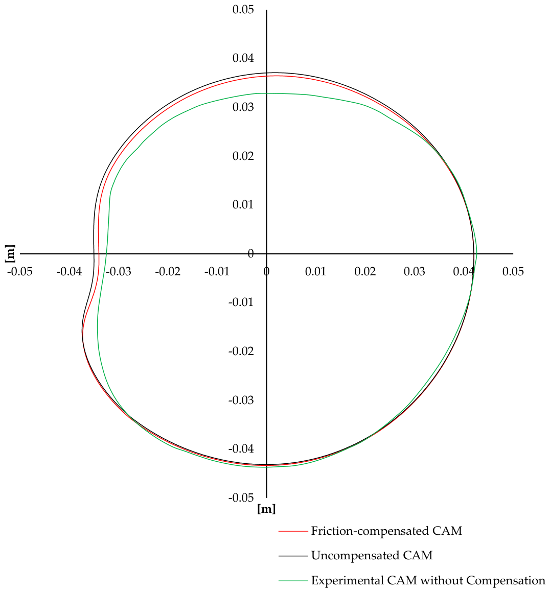
After applying these constraints, the resulting cam geometries can be compared to assess the effect of including the parasitic torque in the profile generation process. Figure 6 presents the comparison between the new cam profiles generated with and without parasitic torque compensation. For reference, the previously developed cam is also included, allowing the geometric changes associated with the transition from an experimentally derived torque profile to a simulated torque-based design to be observed.

2.5. Experimental Implementation and Simulation Methods

The redesigned cam profile was assessed using a combined simulation and experimental procedure, with the same reference engine and balancing mechanism architecture as in the previous validation work. The purpose of this stage was to compare the original engine behavior, the response obtained with the previously validated cam profile, and the response predicted and measured with the redesigned friction-aware cam profile. Since the experimental platform and acquisition procedure had already been validated, the present work focuses on reproducing the same methodology while changing only the cam profile and the corresponding friction-aware torque target.

2.5.1. Simulation Procedure

The simulation model was used to evaluate the torque and angular velocity response over one complete four-stroke cycle. The original engine torque was first simulated as the baseline condition. This profile includes the driving torque generated by cylinder pressure, the inertia torque associated with the moving components, and the resistive torque contributions from valve actuation, lubrication, and friction.
Two compensated configurations were then simulated. The first corresponds to the previously validated cam profile, generated from the smoothed experimentally derived torque profile. The second corresponds to the redesigned cam profile, generated from the selected target torque after friction-aware reformulation. For each configuration, the theoretical torque generated by the balancing cam mechanism was calculated and then corrected by the friction and follower inertia contributions. This allowed the ideal mechanism torque, the friction-aware torque contribution, the effective delivered torque, and the resulting compensated engine torque to be evaluated separately.
The resulting torque profile was obtained by combining the original engine torque with the effective compensating torque delivered by the mechanism. The angular velocity response was then calculated from the resulting torque and the equivalent rotational inertia of the engine system. The same processing was applied to the original engine, the engine with the previous cam profile, and the engine with the redesigned cam profile, allowing direct comparison of torque standard deviation, torque amplitude, angular velocity standard deviation, and angular velocity amplitude.

2.5.2. Experimental Implementation and Data Processing

After satisfying the imposed cam radius and follower stroke constraints, the final roller-corrected cam geometry was produced and installed on the driven gear of the balancing mechanism, replacing the previously validated cam. The remaining mechanism architecture was kept unchanged, ensuring that the comparison of cam profiles was based on the redesigned geometry rather than on changes to the experimental setup.
The cam was phased according to the crank-angle reference used for the 720° engine cycle. After assembly, the follower was brought into contact with the cam, and the spring preload was adjusted to the selected reference value using the threaded follower adjustment system.
Experimental tests were performed on the Honda® GX120 at approximately 1500 rpm after stable operating conditions were established. For each evaluated configuration, ten repeated measurements were acquired. Crankshaft angular velocity was measured using a variable-reluctance sensor and a 36-tooth trigger wheel, corresponding to a crank-angle resolution of 10°. The sensor signal was recorded using a Keysight EDUX1052A digital oscilloscope with a time window of 20 ms/div, a voltage scale of 2 V/div, and 10,000 acquisition points per measurement. Angular velocity was calculated from the time intervals between consecutive teeth. The rising- and falling-edge zero-crossing sequences were processed separately.
The ten resulting 720° angular-velocity profiles were aligned with the crank-angle reference and averaged to obtain a representative cycle for each configuration. Angular acceleration was calculated by numerical differentiation of successive angular-velocity values with respect to time. Instantaneous torque was then reconstructed using an equivalent rotational inertia of 0.01474 kg·m2. This value corresponds to the combined inertia of the engine 0.001254 kg·m2 and the flywheel 0.01349 kg·m2. The same acquisition and processing procedure was applied to all configurations. The 12-value moving average described in Section 2.2.1 was applied only to the experimentally derived torque profile used to synthesize the previous cam, and not to the experimental performance indicators reported in Section 3.2.
Numerical differentiation amplifies local deviations in the measured angular-velocity signal. This effect was reduced by considering both rising- and falling-edge zero-crossing sequences and by averaging ten repeated measurements. During the constant-speed validation of the measurement system, the measured angular-velocity signal exhibited a standard deviation of 0.22 rad/s and a peak-to-peak amplitude of 1.13 rad/s. These values provide an experimental indication of measurement-system dispersion but do not constitute a complete uncertainty budget for the reconstructed torque. Furthermore, because uncertainty in the equivalent rotational inertia produces a proportional scaling uncertainty in the absolute torque values. However, the same inertia value and processing procedure were applied to all configurations, preserving the consistency of the comparative performance assessment.
Performance assessment was based on the standard deviation and peak-to-peak amplitude of both torque and angular velocity.

3. Results

3.1. Simulated Performance of the Redesigned Cam

The redesigned cam profile was evaluated using the same crank-angle-resolved simulation framework used for the reference engine and the previously validated balancing cam. The analysis compares the original engine response with three compensated configurations: the previously validated cam, the redesigned cam generated from the simulated torque profile, and the friction-aware redesigned cam. The comparison focuses on the simulated engine torque and angular velocity response.
Figure 7 presents the original engine torque and the simulated resulting torque obtained with the previously validated cam profile.
The effect of the previous cam profile was quantified using the standard deviation and peak-to-peak amplitude of the torque signal over the complete cycle. The original engine torque presented a standard deviation of 6.77 N·m, while the compensated torque decreased to 2.75 N·m, corresponding to a reduction of approximately 60%. The peak-to-peak torque amplitude was also reduced from 37.32 N·m to 12.74 N·m, corresponding to a reduction of approximately 66%. These results verify the previously validated cam as the reference compensated condition for assessing the redesigned profiles.
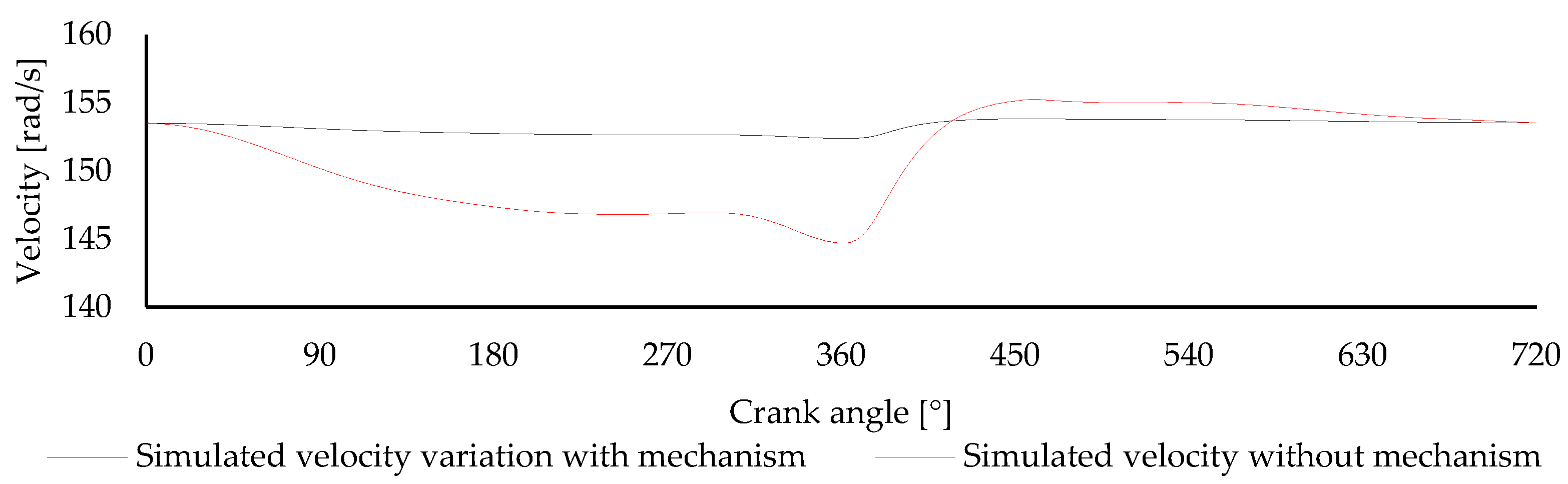
Figure 8 presents the simulated angular velocity response obtained with the previously validated cam profile, compared with the original engine condition. The compensated response shows a clear reduction in angular velocity fluctuation relative to the uncompensated engine, indicating that the torque attenuation observed in Figure 7 is reflected in crankshaft speed stabilization.
The simulated stock condition presented a standard deviation of 3.54 rad/s and a peak-to-peak amplitude of 10.56 rad/s. With the previous cam profile, the simulated angular velocity standard deviation decreased to 1.56 rad/s, while the peak-to-peak amplitude decreased to 5.54 rad/s. These values correspond to reductions of approximately 56% and 48%, respectively.
The redesigned cam generated from the simulated torque profile was then evaluated using the same simulation framework. Figure 9 compares the original simulated engine torque with the resulting compensated torque obtained after applying this redesigned profile. This configuration assesses the effect of using the cycle-resolved simulated torque as the synthesis input, before introducing the friction-aware correction.
The resulting torque curve shows improved torque regularity relative to the original engine condition. With the simulated-profile cam, the torque standard deviation decreased to 1.02 N·m, corresponding to a reduction of approximately 85%. The peak-to-peak amplitude decreased to 6.31 N·m, corresponding to a reduction of approximately 83%. These results indicate that the redesigned profile substantially reduces both overall torque dispersion and the maximum torque range relative to the original condition.
Figure 10 presents the simulated angular velocity response obtained with the redesigned cam generated from the simulated torque profile, compared with the stock engine condition. The compensated response remains closer to the mean angular velocity over the complete 720° cycle, particularly in the regions where the uncompensated engine presents the largest deviations.
As previously presented, the stock angular velocity exhibited a standard deviation of 3.54 rad/s and a peak-to-peak amplitude of 10.56 rad/s. With the simulated-profile cam, the standard deviation decreased to 0.48 rad/s, while the peak-to-peak amplitude decreased to 1.45 rad/s. These values correspond to reductions of approximately 86%. These results confirm that the simulated-profile cam substantially improves crankshaft speed regularity, even though the target torque profile does not yet account for the parasitic torque expected to be introduced by the mechanism.
The final simulated configuration corresponds to the redesigned friction-aware cam profile. In this case, the target torque was reformulated before cam synthesis by incorporating the estimated parasitic torque associated with the compensation mechanism.
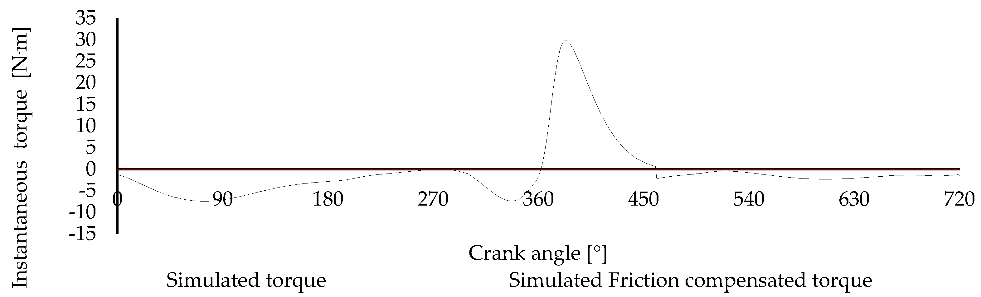
Figure 11 presents the original simulated engine torque and the resulting torque after compensation by the redesigned friction-aware cam mechanism. Because the estimated parasitic torque is incorporated before profile synthesis, the cam is designed to provide the torque required to compensate for both the engine torque fluctuation and the mechanical losses introduced by the mechanism.
Under the nominal model parameters, the friction-aware target cancelled the modelled cyclic torque residual. The resulting torque remained coincident with the zero-torque reference throughout the complete 720° crankshaft cycle, indicating the elimination of the simulated torque fluctuation. Consequently, no residual torque dispersion or peak-to-peak fluctuation was observed in the theoretical response.
This result represents the ideal performance of the proposed compensation approach within the numerical model. It confirms that incorporating the estimated mechanical losses before cam-profile synthesis allows the generated cam torque to compensate for the engine demand after follower friction, contact losses, and inertia effects are considered. The result should therefore be interpreted as the theoretical compensation limit of the redesigned mechanism, while deviations may arise during experimental implementation because of modelling uncertainty, manufacturing tolerances, compliance, and operating-condition variability.
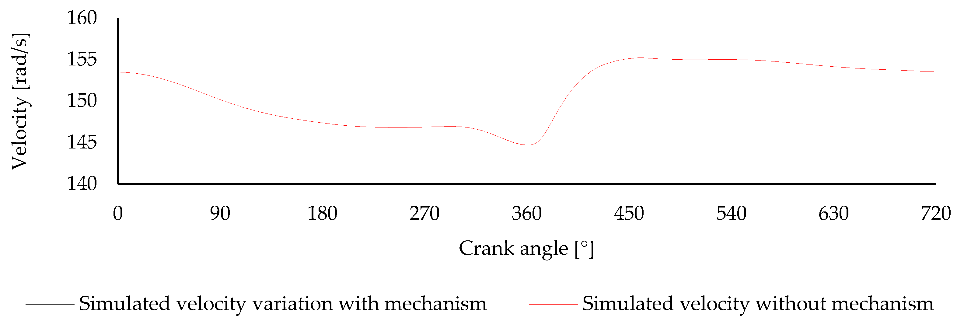
Figure 12 presents the simulated angular velocity response obtained with the redesigned friction-aware cam profile and compares it with the stock engine condition. This comparison evaluates the mechanism’s effect on crankshaft rotational regularity rather than focusing solely on reducing instantaneous torque fluctuations.
Under the adopted simulation assumptions, the redesigned friction-aware cam produces zero residual torque fluctuations and maintains a constant angular velocity throughout the entire engine cycle. The simulated crankshaft speed remains coincident with its mean value, with no cyclic dispersion or peak-to-peak variation. This response is consistent with the torque compensation shown in Figure 11, since eliminating the residual torque fluctuation prevents cyclic crankshaft acceleration and deceleration.
However, this result should not be interpreted as an independent validation of perfect compensation. Since the same nominal loss model is used both to construct the corrected target torque and to evaluate the resulting response, it represents a theoretical model-consistency or closure condition. Exact compensation is therefore obtained when the model assumptions and nominal parameters are internally consistent, defining the theoretical compensation limit of the proposed formulation.
The resulting constant angular velocity also implies the elimination of the corresponding angular acceleration variation within the numerical model. Consequently, the inertia torque associated with cyclic crankshaft acceleration is suppressed in the ideal simulated response. This may also reduce the inertia-dependent component of the mechanism losses, although losses related to spring preload, contact forces, support friction, and local deformation remain dependent on the mechanism’s physical characteristics.
Overall, the simulated results indicate that incorporating the estimated parasitic torque before cam-profile synthesis enables the redesigned mechanism to reach the theoretical compensation limit of the model.
Table 2 summarizes the simulated torque and angular-velocity indicators for the stock engine and the three compensated configurations. The results show a progressive reduction in cyclic fluctuations from the previous cam to the simulated-profile cam.

3.2. Experimental Results

The experimental assessment was carried out for three operating conditions: the stock engine, the previously validated cam, identified in the figures as the previous cam, and the redesigned cam, identified as the friction-aware redesigned cam. The comparison uses the same performance indicators adopted in the simulation analysis: standard deviation and peak-to-peak amplitude of the angular velocity and reconstructed instantaneous torque.
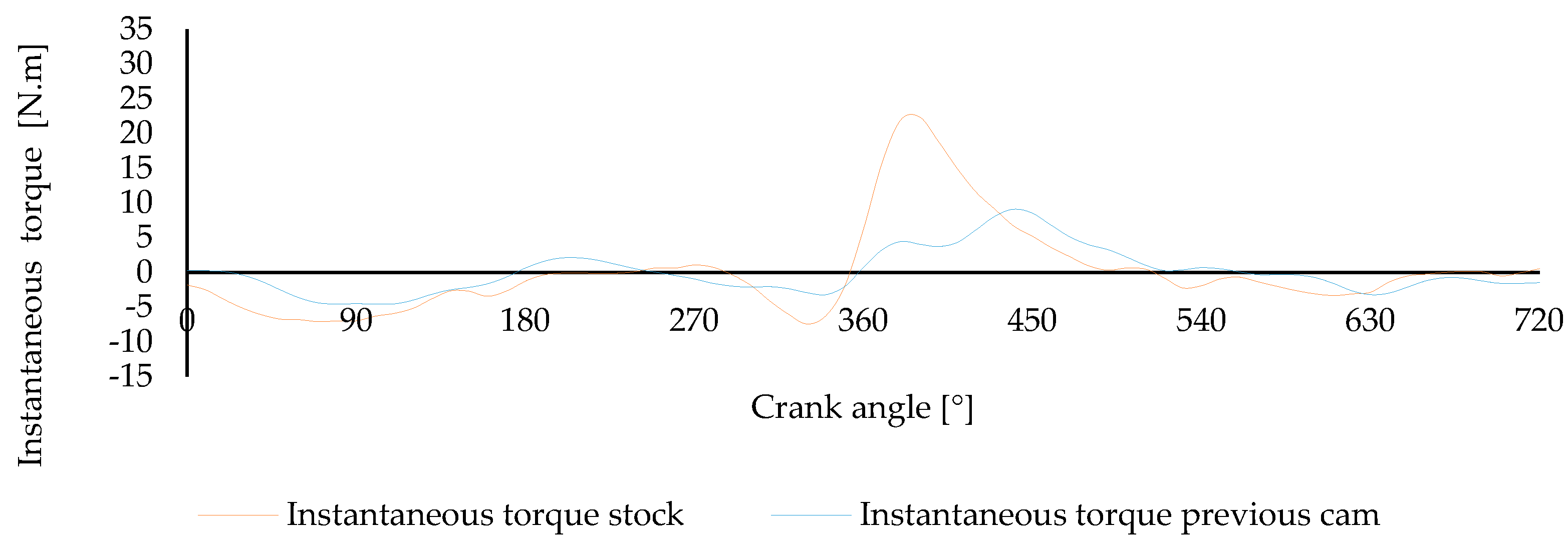
Figure 13 compares the experimentally reconstructed instantaneous torque of the stock engine with the torque response obtained using the validated previous cam. The stock condition shows the highest cyclic torque variation, with a pronounced positive torque region after combustion and negative torque contributions during the remaining cycle. The previous cam reduces the magnitude of these fluctuations, confirming the compensation effect of the passive cam–spring mechanism under laboratory conditions.
The reconstructed torque standard deviation decreased from 6.25 N·m in the stock condition to 3.12 N·m with the previous cam, corresponding to a reduction of 50%. The peak-to-peak torque amplitude decreased from 29.79 N·m to 13.66 N·m, corresponding to a reduction of 54%. These results confirm that the previously validated cam substantially attenuates the torque ripple of the stock engine.
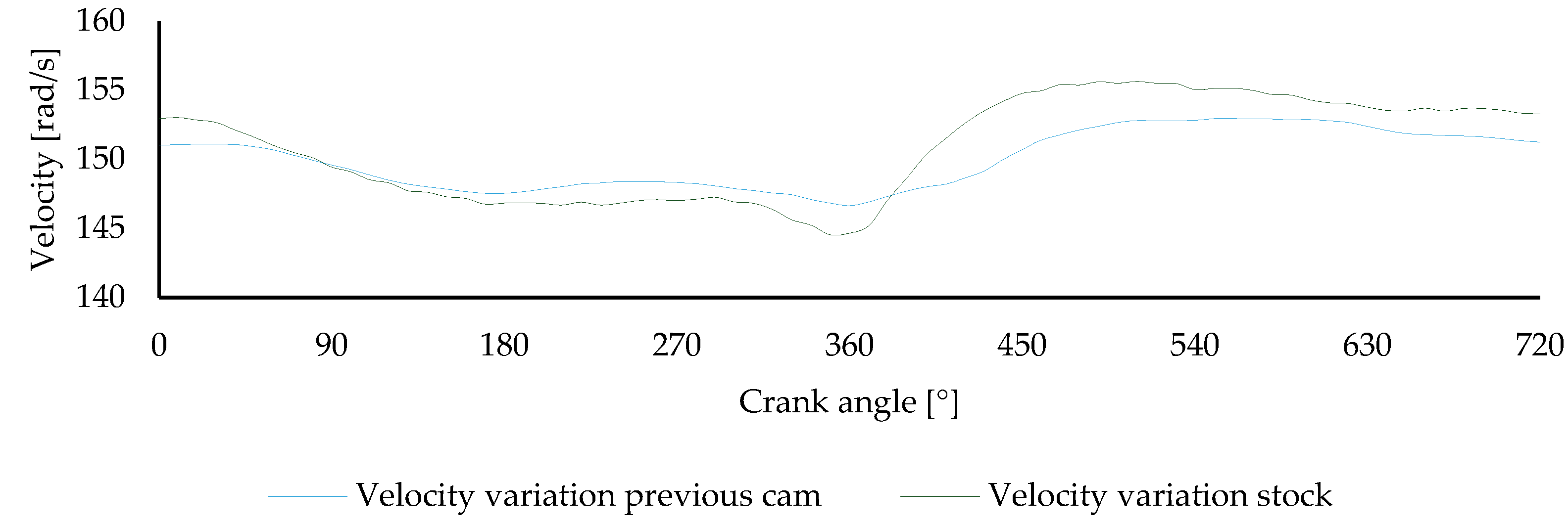
Figure 14 presents the corresponding angular velocity response for the stock engine and the previous cam. The stock condition shows the largest speed variation over the 720° cycle, especially around the compression and expansion regions. With the previous cam, the angular velocity profile becomes more uniform, indicating that the reduction in torque fluctuation is transferred to crankshaft speed stabilization.
The angular velocity standard deviation decreased from 3.58 rad/s in the stock condition to 2.07 rad/s with the previous cam, corresponding to a reduction of 43%. The peak-to-peak angular velocity amplitude decreased from 11.08 rad/s to 6.30 rad/s, corresponding to a reduction of 43%.
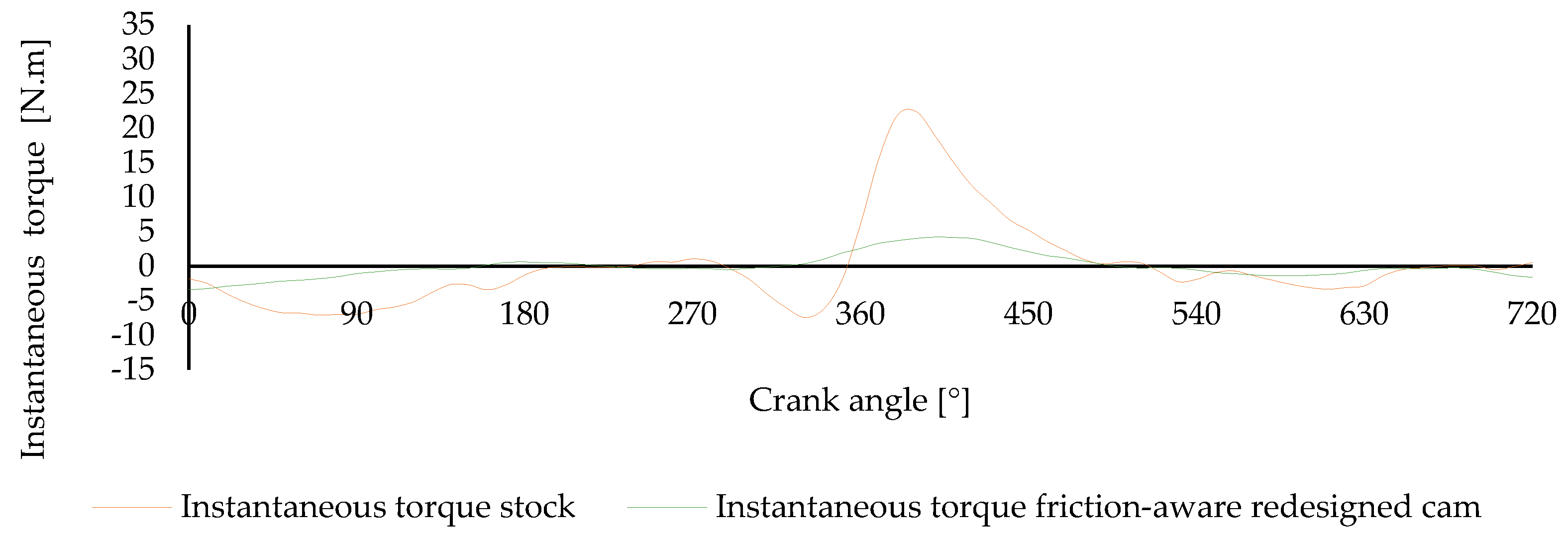
Figure 15 compares the stock torque response with the torque obtained using the friction-aware redesigned cam. This profile produces a lower residual torque fluctuation than the previous cam, with a more pronounced reduction in the high-torque region after combustion. The result indicates that the redesigned profile improves the effective compensation delivered by the mechanism.
With the friction-aware redesigned cam, the reconstructed torque standard deviation decreased from 6.25 N·m to 1.71 N·m, corresponding to a reduction of 73% relative to the stock condition. The peak-to-peak torque amplitude decreased from 29.79 N·m to 7.66 N·m, corresponding to a reduction of 74%.
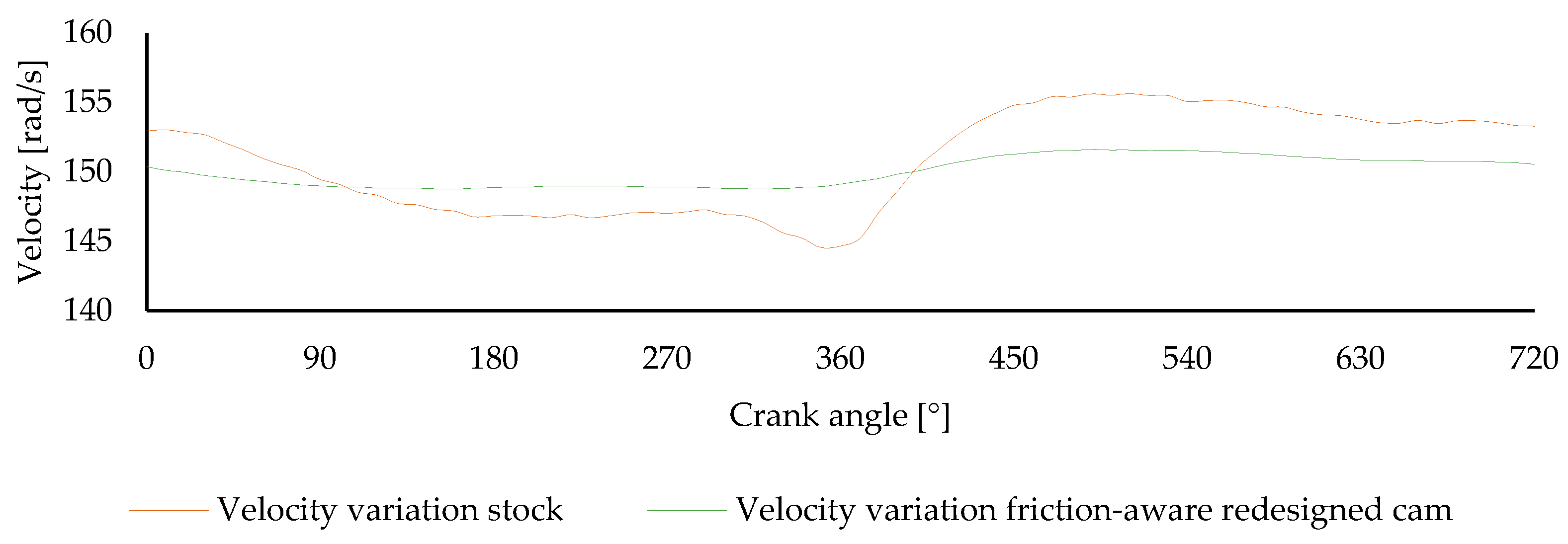
Figure 16 presents the angular velocity response obtained with the friction-aware redesigned cam, compared with the stock condition. The redesigned cam maintains the crankshaft speed closer to the average value over the complete cycle, reducing both the minimum velocity drop before combustion and the subsequent velocity increase during expansion.
The angular velocity standard deviation decreased from 3.58 rad/s in the stock condition to 1.05 rad/s with the friction-aware redesigned cam, corresponding to a reduction of 71%. The peak-to-peak angular velocity amplitude decreased from 11.08 rad/s to 2.86 rad/s, corresponding to a reduction of 74%.
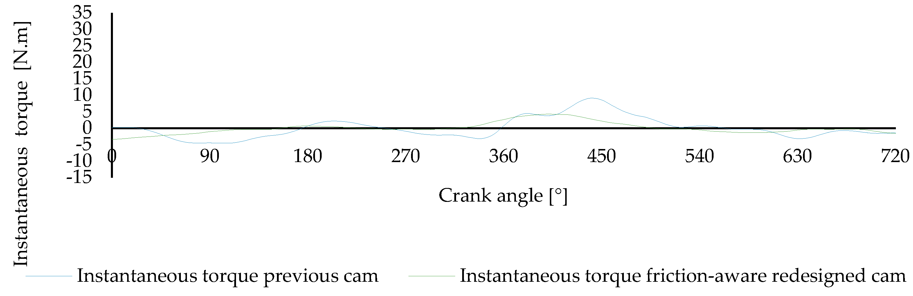
Figure 17 directly compares the reconstructed torque responses obtained with the previous cam and the friction-aware redesigned cam. This comparison isolates the effect of the redesigned profile, since both configurations were tested using the same engine and mechanism architecture. The friction-aware redesigned cam presents a lower residual torque fluctuation over most of the cycle, particularly after combustion, where the previous cam still shows a larger compensated torque peak.
Relative to the previous cam, the friction-aware redesigned cam reduced the torque standard deviation from 3.12 N·m to 1.71 N·m, corresponding to a further reduction of 45%. The peak-to-peak torque amplitude decreased from 13.66 N·m to 7.66 N·m, corresponding to a further reduction of 44%.
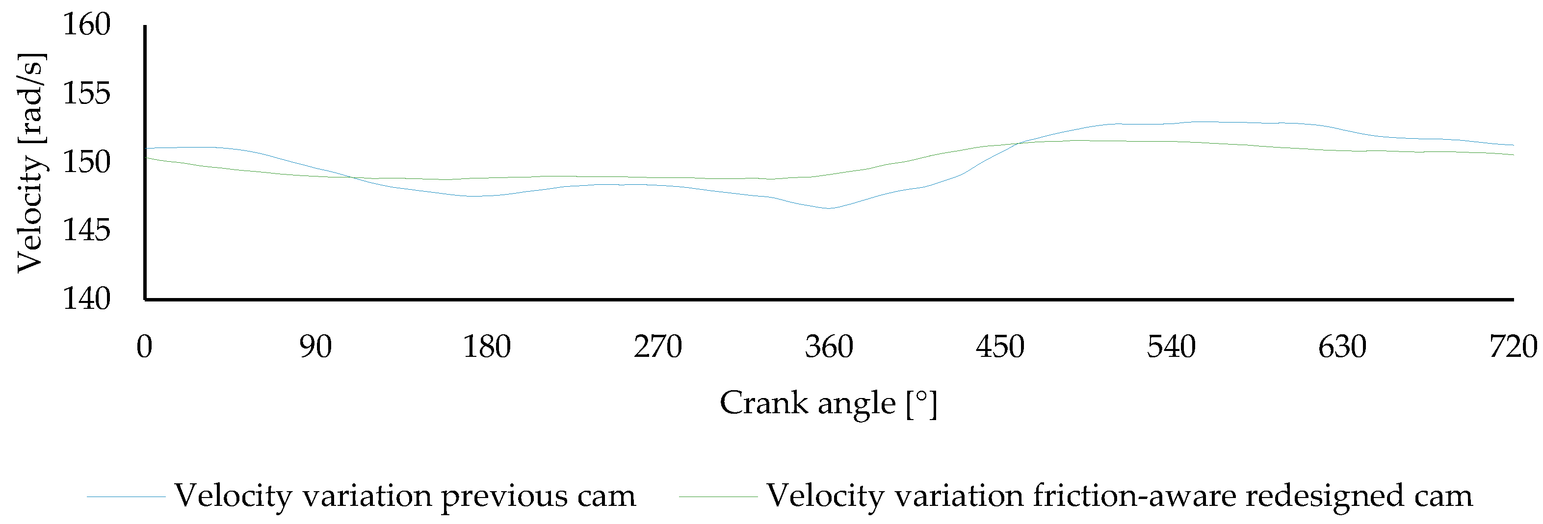
Figure 18 compares the angular velocity responses obtained with the previous cam and the friction-aware redesigned cam. The redesigned profile produces a smoother velocity curve, with lower deviation from the mean value throughout the engine cycle. This confirms that the reduction in reconstructed torque ripple also improves crankshaft rotational regularity.
Compared with the previous cam, the friction-aware redesigned cam reduced the angular velocity standard deviation from 2.07 rad/s to 1.05 rad/s, corresponding to a further reduction of 50%. The peak-to-peak angular velocity amplitude decreased from 6.30 rad/s to 2.86 rad/s, corresponding to a further reduction of 55%.
Table 3 summarizes the experimental torque and angular-velocity indicators for the stock engine, previous cam, and friction-aware redesigned cam.

4. Discussion

4.1. Effect of Torque Input Selection

The results show that the performance improvement obtained with the redesigned cam is associated with two complementary aspects: selecting a more representative torque input and accounting for expected mechanism losses before generating the cam profile. The simulated torque profile provided a more suitable basis for cam synthesis than the 12-value moving-average experimental profile. This is because it avoided local oscillations associated with experimental acquisition and numerical differentiation, while preserving the main torque features required for compensation. As a result, the cam generated from the simulated torque profile provided stronger compensation than the previously validated cam, without requiring excessive smoothing of the target torque.
This effect is clearly observed in the simulated results. The previously validated cam reduced the simulated torque standard deviation from 6.77 N·m to 2.75 N·m. The cam generated from the simulated torque profile was reduced further to 1.02 N·m. The peak-to-peak torque amplitude decreased from 37.32 N·m in the original simulated condition to 12.74 N·m with the previous cam and 6.31 N·m with the simulated-profile cam. These results indicate that using the cycle-resolved simulated torque profile improved compensation by retaining torque features attenuated in the smoothed experimental profile.
A similar trend is observed in the simulated angular velocity response. The original simulated angular velocity showed a standard deviation of 3.54 rad/s and a peak-to-peak amplitude of 10.56 rad/s. With the previous cam profile, the standard deviation dropped to 1.56 rad/s and the peak-to-peak amplitude to 5.54 rad/s. With the simulated-profile cam, the standard deviation decreased further to 0.48 rad/s, and the peak-to-peak amplitude to 1.45 rad/s. These reductions confirm that improved torque compensation directly led to greater crankshaft speed stabilization.
The friction-aware reformulation represents a further development of the design procedure. Instead of generating the cam from an ideal compensating torque and evaluating losses afterward, the target torque was corrected before synthesis by incorporating the estimated parasitic torque introduced by the mechanism. This includes support friction, contact-related effects, and follower inertia. Under the adopted simulation assumptions, this approach enabled the friction-aware cam to reach the theoretical compensation limit of the model, with the residual torque fluctuations and the corresponding cyclic angular velocity variations eliminated in the numerical response.
Therefore, the simulated results should be interpreted at two levels. First, the cam generated from the simulated torque profile demonstrates the benefit of selecting a more representative torque input for cam synthesis. Second, the friction-aware profile demonstrates the ideal compensation capability achievable when estimated mechanism losses are incorporated into the cam generation process. The experimental implementation is expected to approach, but not fully reach, this ideal limit because real mechanical systems are affected by additional uncertainties that cannot be fully represented in the model.

4.2. Agreement Between Simulated and Experimental Performance

The experimental results confirmed the same performance trend predicted by the simulation. The previously validated cam reduced torque ripple and angular velocity fluctuation relative to the stock engine, while the redesigned cam provided an additional reduction in both indicators. Experimentally, the instantaneous torque standard deviation decreased from 6.25 N·m in the stock condition to 1.71 N·m with the redesigned cam, corresponding to a 73% reduction. The torque peak-to-peak amplitude decreased from 29.79 N·m to 7.66 N·m, corresponding to a 74% reduction.
The improvement was also observed in the measured angular velocity response. The angular velocity standard deviation decreased from 3.58 rad/s in the stock condition to 1.05 rad/s with the redesigned cam, corresponding to a 71% reduction. The peak-to-peak angular velocity amplitude decreased from 11.08 rad/s to 2.86 rad/s, corresponding to a 74% reduction. These results show that the reduction in reconstructed torque ripple was transferred to improved crankshaft rotational regularity.
Compared with the previously validated cam, the redesigned profile also provided a clear experimental improvement. The torque standard deviation decreased from 3.12 N·m to 1.71 N·m, corresponding to a further reduction of 45%. The torque peak-to-peak amplitude decreased from 13.66 N·m to 7.66 N·m, corresponding to a further reduction of 44%. The angular velocity standard deviation decreased from 2.07 rad/s to 1.05 rad/s, corresponding to a further reduction of 50%, while the peak-to-peak angular velocity amplitude decreased from 6.30 rad/s to 2.86 rad/s, corresponding to a further reduction of 55%.
Although the experimental response followed the same trend as the simulation, the measured reductions were lower than the ideal friction-aware numerical prediction. This difference is expected for a passive mechanical system. The simulation includes the main friction and inertia terms considered during synthesis, but the real mechanism is also affected by local contact variability, preload adjustment uncertainty, assembly tolerances, structural compliance, and cycle-to-cycle combustion variability. These effects reduce the effective torque delivered by the mechanism, explaining why the experimental angular velocity standard deviation remained higher than the ideal simulated response.
The comparison between simulation and experiment, therefore, confirms the validity of the proposed design approach without implying that the numerical ideal can be fully reproduced experimentally.

4.3. Mechanical Implications and Limitations

The results indicate that the redesigned cam improves compensation not by eliminating mechanical losses, but by accounting for their expected contribution during profile generation. This reduces under-compensation in the regions where the mechanism is more affected by preload-dependent reactions and follower motion. As a result, the cam profile better links the required compensating torque, the expected parasitic effects, and the manufacturable geometry.
Nevertheless, the mechanism remains constrained by its passive nature. The spring preload is fixed during operation and cannot adapt to variations in engine speed, load, combustion variability, or thermal conditions. In addition, the cam profile must remain within the available cam-radius range and follower-stroke limit. These constraints prevent complete cancellation of torque fluctuation in the experimental prototype, even when the target torque is accurately defined in the numerical model.
The predicted optimal compensation for the friction-aware cam should therefore be interpreted as the theoretical limit of the model rather than as a directly achievable experimental condition. In practice, deviations from the ideal response are introduced by manufacturing tolerances, contact conditions, preload uncertainty, component compliance, friction variability, and cycle-to-cycle engine behavior. These effects are especially relevant in a mechanically coupled passive system, where the compensating torque generated depends directly on the physical interactions among the cam, roller follower, spring, and support structure.
The proposed methodology is not inherently restricted to the Honda® GX120. It can be adapted to other engines by incorporating their specific torque profiles, operating conditions, mechanical-loss parameters, and design constraints. However, the experimental validation presented here was conducted solely on a Honda® GX120 single-cylinder engine at about 1500 rpm. Idle was chosen for initial design and validation because it represents the most demanding condition considered in this study regarding cyclic torque and angular-velocity fluctuations. After validating and selecting the best-performing cam profile under idle, future work will broaden the experimental assessment to different engine speeds and loads. This extension will help determine if the redesigned cam maintains effective compensation across a wider operating range. If it does not, strategies such as adjustable spring preload, interchangeable cam profiles, or hybrid passive–active compensation may be considered. Further experimental validation will also be necessary to quantify the methodology’s performance for other engine architectures.

5. Conclusions

This study proposed and validated a methodology for redesigning balancing cam profiles for passive torque and angular velocity stabilization in combustion engines. The work builds on a previously validated cam–spring mechanism, but updates the design process by focusing on torque input selection, loss-aware profile generation, and manufacturability constraints.
The comparison between torque inputs showed that a cycle-resolved simulated torque profile is more suitable for cam synthesis than the 12-value moving-average experimental profile used in the previous design. The simulated profile reduced the NRMSE by approximately 36% compared with the smoothed experimental version, while avoiding local oscillations associated with experimental acquisition and numerical differentiation. This allowed the cam synthesis procedure to preserve relevant torque features without generating an impractical geometry.
The redesigned cam generated from the simulated torque profile produced a substantial improvement in the numerical response. In the simulation, the torque standard deviation decreased from 6.77 N·m in the original condition to 1.02 N·m, corresponding to a reduction of approximately 85%. The peak-to-peak torque amplitude decreased from 37.32 N·m to 6.31 N·m, corresponding to a reduction of approximately 83%. The angular velocity standard deviation decreased from 3.54 rad/s to 0.48 rad/s, while the peak-to-peak angular velocity amplitude decreased from 10.56 rad/s to 1.45 rad/s. These values correspond to reductions of approximately 87%. These results confirm the importance of selecting an appropriate torque input for cam synthesis.
The friction-aware reformulation further extended the design procedure by incorporating the estimated parasitic torque before cam profile generation. This included follower support friction, contact-related effects, and follower inertia. Under the adopted simulation assumptions, this approach represented the theoretical compensation limit of the model, eliminating the residual torque fluctuation and the corresponding cyclic angular velocity variation. This ideal result should not be interpreted as a directly achievable experimental condition, but rather as the numerical limit obtained when the estimated mechanism losses are fully compensated during cam synthesis.
The experimental validation confirmed the same performance trend. The redesigned cam reduced the experimentally reconstructed instantaneous torque standard deviation from 6.25 N·m to 1.71 N·m, corresponding to a 73% reduction relative to the stock engine. The torque peak-to-peak amplitude decreased from 29.79 N·m to 7.66 N·m, corresponding to a 74% reduction. The angular velocity standard deviation decreased from 3.58 rad/s to 1.05 rad/s, corresponding to a 71% reduction, while the peak-to-peak angular velocity amplitude decreased from 11.08 rad/s to 2.86 rad/s, corresponding to a 74% reduction.
Compared with the previously validated cam, the redesigned profile also provided a clear experimental improvement. The reconstructed torque standard deviation decreased by 45%, while the torque peak-to-peak amplitude decreased by 44%. The angular velocity standard deviation decreased by 50%, and the peak-to-peak angular velocity amplitude decreased by 55%. These results confirm that the redesigned cam improved the effective compensation delivered by the passive balancing mechanism under laboratory operating conditions.
Overall, the proposed methodology improves the link between the required compensating torque, the expected mechanical losses, and the manufacturable cam geometry. Although the passive mechanism remains limited by fixed preload, contact conditions, and geometric constraints, the results demonstrate that loss-aware cam synthesis can improve torque ripple attenuation and crankshaft speed stabilization without requiring active control.
Future work should extend this procedure to variable preload configurations, broader speed and load ranges, and alternative engine architectures. Further studies should also assess its applicability to multi-cylinder engines and hybrid powertrain configurations, where passive torque stabilization may complement conventional flywheels, damping devices, or active control strategies.

6. Patents

This and subsequent works resulted in a patent application submitted to the Portuguese Institute of Industrial Property (INPI) under application number 119346, with the title “Método Implementado por Computador para a Conceção de um Atuador de Equilíbrio para um Motor, Atuador de Equilíbrio, Programa de Computador e Meio de Leitura Associados.”

Author Contributions

Conceptualization, D.S.C. and P.O.F.; methodology, D.S.C. and P.O.F.; validation, P.O.F. and P.D.G.; formal analysis, P.O.F. and P.D.G.; investigation, D.S.C. and P.O.F.; data curation, P.O.F.; writing—original draft preparation, D.S.C. and H.L.; writing—review and editing, D.S.C., P.O.F., H.L. and P.D.G.; supervision, P.O.F. and P.D.G. All authors have read and agreed to the published version of the manuscript.

Funding

This research was funded in part by the Fundação para a Ciência e Tecnologia (FCT) and C-MAST (Centre for Mechanical and Aerospace Science and Technologies) for their support in the form of funding, under the project UIDB/00151/2020 (https://doi.org/10.54499/UIDB/00151/2020, accessed on 2 April 2025).

Data Availability Statement

The original contributions presented in the study are included in the article. Further inquiries can be directed to the corresponding author.

Conflicts of Interest

The authors declare no conflicts of interest.

References

  1. Solmaz, H.; Karabulut, H. A mathematical model to investigate the effects of misfire and cyclic variations on crankshaft speed fluctuations in internal combustion engines. J. Mech. Sci. Technol. 2015, 29, 1493–1500. [Google Scholar] [CrossRef]
  2. Babagiray, M.; Solmaz, H.; İpci, D.; Aksoy, F. Modeling and validation of crankshaft speed fluctuations of a single-cylinder four-stroke diesel engine. Proc. Inst. Mech. Eng. Part D. J. Automob. Eng. 2022, 236, 553–568. [Google Scholar] [CrossRef]
  3. Silva Cardoso, D.; Oliveira Fael, P.; Espírito-Santo, A. Instantaneous angular velocity and torque on Otto single-cylinder engine: A theoretical and experimental analysis. Energy Rep. 2020, 6, 43–48. [Google Scholar] [CrossRef]
  4. Filipi, Z.S.; Assanis, D.N. A Nonlinear, Transient, Single-Cylinder Diesel Engine Simulation for Predictions of Instantaneous Engine Speed and Torque. J. Eng. Gas. Turbines Power 2001, 123, 951–959. [Google Scholar] [CrossRef]
  5. Antonopoulos, A.K.; Hountalas, D.T. Effect of instantaneous rotational speed on the analysis of measured diesel engine cylinder pressure data. Energy Convers. Manag. 2012, 60, 87–95. [Google Scholar] [CrossRef]
  6. Cardoso, D.; Nunes, D.; Faria, J.; Fael, P.; Gaspar, P.D. Intelligent Micro-Cogeneration Systems for Residential Grids: A Sustainable Solution for Efficient Energy Management. Energies 2023, 16, 5215. [Google Scholar] [CrossRef]
  7. Mittal, V.; Shah, R.; Przyborowski, A. Analyzing the Usage of Wankel Engine Technology in Future Automotive Powertrains. SAE Int. J. Sustain. Transp. Energy Environ. Policy 2024, 5, 115–127. [Google Scholar] [CrossRef]
  8. Schaper, U.; Sawodny, O.; Mahl, T.; Blessing, U. Modeling and torque estimation of an automotive dual mass flywheel. In Proceedings of the American Control Conference, St. Louis, MO, USA, 10–12 June 2009; pp. 1207–1212. [Google Scholar] [CrossRef]
  9. Munde, K.H.; Mehtre, V.K.; Ware, D.S.; Kamble, D.P. Review on Performance of Dual Mass Flywheel over Conventional Flywheel. Math. Stat. Eng. Appl. 2022, 71, 496–505. [Google Scholar] [CrossRef]
  10. A Review Paper on Vibration Analysis of DI Engine. Available online: https://www.ijsr.net/getabstract.php?paperid=SUB151324 (accessed on 12 June 2026).
  11. Ayana, E.; Plahn, P.; Wejrzanowski, K.; Mohan, N. Active torque cancellation for transmitted vibration reduction of low cylinder count engines. IEEE Trans. Veh. Technol. 2011, 60, 2971–2977. [Google Scholar] [CrossRef]
  12. Anjum, R.; Yar, A.; Ahmed, Q.; Bhatti, A. Model Based Unified Framework for Detection and Mitigation of Cyclic Torque Imbalance in a Gasoline Engine. J. Eng. Gas. Turbines Power 2021, 143, 071013. [Google Scholar] [CrossRef]
  13. Zhang, X.; Liu, H.; Zhan, Z.; Wu, Y.; Zhang, W.; Taha, M.; Yan, P. Modelling and active damping of engine torque ripple in a power-split hybrid electric vehicle. Control Eng. Pract. 2020, 104, 104634. [Google Scholar] [CrossRef]
  14. Galvagno, E.; Velardocchia, M.; Vigliani, A.; Tota, A. Experimental Analysis and Model Validation of a Dual Mass Flywheel for Passenger Cars. In Proceedings of the SAE 2015 World Congress & Exhibition, Detroit, MI, USA, 21 April 2015. [Google Scholar] [CrossRef]
  15. Pfabe, M.; Woernle, C. Reducing torsional vibrations by means of a kinematically driven flywheel—Theory and experiment. Mech. Mach. Theory 2016, 102, 217–228. [Google Scholar] [CrossRef]
  16. Zhang, Y.; Zhang, X.; Qian, T.; Hu, R. Modeling and simulation of a passive variable inertia flywheel for diesel generator. Energy Rep. 2020, 6, 58–68. [Google Scholar] [CrossRef]
  17. Kim, G.-W.; Shin, S.-C. Research on the torque transmissibility of the passive torsional vibration isolator in an automotive clutch damper. Proc. Inst. Mech. Eng. Part D. J. Automob. Eng. 2015, 229, 1840–1847. [Google Scholar] [CrossRef]
  18. Cardoso, D.S.; Fael, P.O.; Gaspar, P.D.; Espírito-Santo, A. An Innovative Mechanical Approach to Mitigating Torque Fluctuations in IC Engines during Idle Operation. Designs 2024, 8, 47. [Google Scholar] [CrossRef]
  19. Cardoso, D.S.; Fael, P.O.; Gaspar, P.D.; Espírito-Santo, A. Balancing Cam Mechanism for Instantaneous Torque and Velocity Stabilization in Internal Combustion Engines: Simulation and Experimental Validation. Energies 2025, 18, 3256. [Google Scholar] [CrossRef]
  20. Arakelian, V.; Briot, S. Simultaneous inertia force/moment balancing and torque compensation of slider-crank mechanisms. Mech. Res. Commun. 2010, 37, 265–269. [Google Scholar] [CrossRef]
  21. Lin, D.Y.; Hou, B.J.; Lan, C.C. A balancing cam mechanism for minimizing the torque fluctuation of engine camshafts. Mech. Mach. Theory 2017, 108, 160–175. [Google Scholar] [CrossRef]
  22. Porumb, I.; Marian, R.; Doğançay, K.; Chahl, J.S. Robust Instant Angle Speed Measurement for Internal Combustion Engines—A Novel Sensing Suite and Methodology. Sensors 2022, 22, 754. [Google Scholar] [CrossRef] [PubMed]
  23. Zhixiong, L.; Zhiwei, G.; Chongqing, H.; Aihua, L. On-line indicated torque estimation for internal combustion engines using discrete observer. Comput. Electr. Eng. 2017, 60, 100–115. [Google Scholar] [CrossRef]
  24. Addabbo, T.; Di Marco, M.; Fort, A.; Landi, E.; Mugnaini, M.; Vignoli, V.; Ferretti, G. Instantaneous rotation speed measurement system based on variable reluctance sensors for torsional vibration monitoring. IEEE Trans. Instrum. Meas. 2019, 68, 2363–2373. [Google Scholar] [CrossRef]
  25. Ali, S.A.; Saraswati, S. Cycle-by-cycle estimation of cylinder pressure and indicated torque waveform using crankshaft speed fluctuations. Trans. Inst. Meas. Control 2015, 37, 813–825. [Google Scholar] [CrossRef]
  26. Tong, Q.; Xie, H.; Song, K.; Zou, D. A control-oriented engine torque online estimation approach for gasoline engines based on in-cycle crankshaft speed dynamics. Energies 2019, 12, 4683. [Google Scholar] [CrossRef]
  27. Blair, G.P. Design and Simulation of Four-Stroke Engines; SAE International: Warrendale, PA, USA, 1999; p. 815. [Google Scholar]
  28. Uicker, J.J. Theory of Machines and Mechanisms; Oxford University Press: London, UK, 1980. [Google Scholar]
  29. Budynas, R.G.; Nisbett, J.K.; Edward, J.; Shigley, J.E. Shigley’s Mechanical Engineering Design; McGraw-Hill: Columbus, OH, USA, 2011. [Google Scholar]
Figure 1. Exploded view of the balancing mechanism assembly: (1) support structure; (2) M8 fastening bolts; (3) variable reluctance sensor; (4) fastening bolt; (5) follower assembly; (6) 20-tooth gear with trigger wheel; (7) 40-tooth gear with cam; (8) M16 locking nuts.
Energies 19 03724 g001
Figure 2. Comparison of torque profiles for the Honda® GX120 engine at 1500 rpm over a complete 720° cycle: cycle-resolved simulated torque, experimentally obtained torque, and experimentally obtained smoothed torque profile using a 12-value moving average.
Energies 19 03724 g002
Figure 3. Diagram of the balancing cam mechanism used to derive the geometric and force relationships required for cam profile synthesis [19].
Energies 19 03724 g003
Figure 4. Mechanical model used to analyse support reactions and friction caused by the tangential force F t [19].
Energies 19 03724 g004
Figure 5. Comparison between the uncompensated and friction-compensated torque profiles over one complete engine cycle. The yellow bounds represent the torque range obtained by applying a simultaneous ±10% variation to the nominal loss-model parameters.
Energies 19 03724 g005
Figure 6. Comparison of cam profiles generated from the friction-compensated and uncompensated simulated torque profiles, with the previously developed cam included as a reference.
Energies 19 03724 g006
Figure 7. Simulated resulting torque obtained with the previously validated balancing cam mechanism, compared with the original torque profile of the Honda® GX120 engine.
Energies 19 03724 g007
Figure 8. Simulated angular velocity response of the Honda® GX120 engine for the original engine condition and the previous cam profile.
Energies 19 03724 g008
Figure 9. Torque delivered by the redesigned balancing cam mechanism, generated from the simulated torque profile and resulting compensated torque compared with the original simulated torque profile of the Honda® GX120 engine.
Energies 19 03724 g009
Figure 10. Simulated angular velocity response of the Honda® GX120 engine with the redesigned cam generated from the simulated torque profile, compared with the stock engine condition.
Energies 19 03724 g010
Figure 11. Simulated torque response obtained with the redesigned friction-aware cam mechanism, compared with the original simulated torque profile of the Honda® GX120 engine.
Energies 19 03724 g011
Figure 12. Simulated angular velocity response of the Honda® GX120 engine with the friction-aware redesigned cam profile, compared with the stock engine condition.
Energies 19 03724 g012
Figure 13. Experimentally reconstructed instantaneous torque response of the Honda® GX120 engine at 1500 rpm for the stock condition and the previous cam.
Energies 19 03724 g013
Figure 14. Experimental angular velocity response of the Honda® GX120 engine at 1500 rpm for the stock condition and the previous cam.
Energies 19 03724 g014
Figure 15. Experimentally reconstructed instantaneous torque response of the Honda® GX120 engine at 1500 rpm for the stock condition and the friction-aware redesigned cam.
Energies 19 03724 g015
Figure 16. Experimental angular velocity response of the Honda® GX120 engine at 1500 rpm for the stock condition and the friction-aware redesigned cam.
Energies 19 03724 g016
Figure 17. Experimentally reconstructed instantaneous torque response of the Honda® GX120 engine at 1500 rpm for the validated previous cam and the friction-aware redesigned cam.
Energies 19 03724 g017
Figure 18. Experimental angular velocity response of the Honda® GX120 engine at 1500 rpm for the validated previous cam and the friction-aware redesigned cam.
Energies 19 03724 g018
Table 1. Main parameters used in the mechanical-loss model.
ParameterValue
Friction coefficient at support A ( μ A )0.03
Friction coefficient at support B ( μ B ) 0.20
Effective moving follower mass ( m f )0.175 kg
Spring preload ( P ) 242 N
Spring stiffness ( k )24.2 kN/m
Table 2. Summary of the simulated performance indicators for the evaluated engine and cam configurations.
ConfigurationTorque Standard DeviationTorque Peak-to-Peak Amplitude Angular Velocity Standard DeviationAngular Velocity Peak-to-Peak Amplitude
Stock engine6.77 N·m37.32 N·m3.54 rad/s10.56 rad/s
Previous cam2.75 N·m12.74 N·m1.56 rad/s5.54 rad/s
Simulated-profile cam1.02 N·m6.31 N·m0.48 rad/s1.45 rad/s
Friction-aware redesigned cam0 * N·m0 * N·m0 * rad/s0 * rad/s
* The zero values represent the theoretical model-closure condition under the nominal simulation assumptions and do not constitute independent experimental validation.
Table 3. Summary of the experimental performance indicators for the evaluated engine and cam configurations.
ConfigurationTorque Standard DeviationTorque Peak-to-Peak Amplitude Angular Velocity Standard DeviationAngular Velocity Peak-to-Peak Amplitude
Stock engine6.25 N·m29.79 N·m3.58 rad/s11.08 rad/s
Previous cam3.12 N·m13.66 N·m2.07 rad/s6.30 rad/s
Friction-aware redesigned cam1.71 N·m7.66 N·m1.05 rad/s2.86 rad/s
Disclaimer/Publisher’s Note: The statements, opinions and data contained in all publications are solely those of the individual author(s) and contributor(s) and not of MDPI and/or the editor(s). MDPI and/or the editor(s) disclaim responsibility for any injury to people or property resulting from any ideas, methods, instructions or products referred to in the content.