1. Introduction
In the early years of spark plug production, materials such as nickel were used for electrodes. In the following years, copper cores were added to improve electrical and thermal conductivity [
1]. The durability of these early spark plugs was surprisingly low. In subsequent years, spark plug development involved, among other things, replacing natural materials used as electrical insulators with sintered aluminum oxide (Al
2O
3) [
2]. Simultaneously, experiments were conducted on the number and shape of electrodes to improve the durability of such plugs [
3,
4]. Current spark plug materials include nickel–chromium steel for the body and electrodes. Modern spark plug electrodes are equipped with an additional tip, additional elements made of high melting point materials such as iridium or platinum, which come into direct contact with the spark discharge [
5].
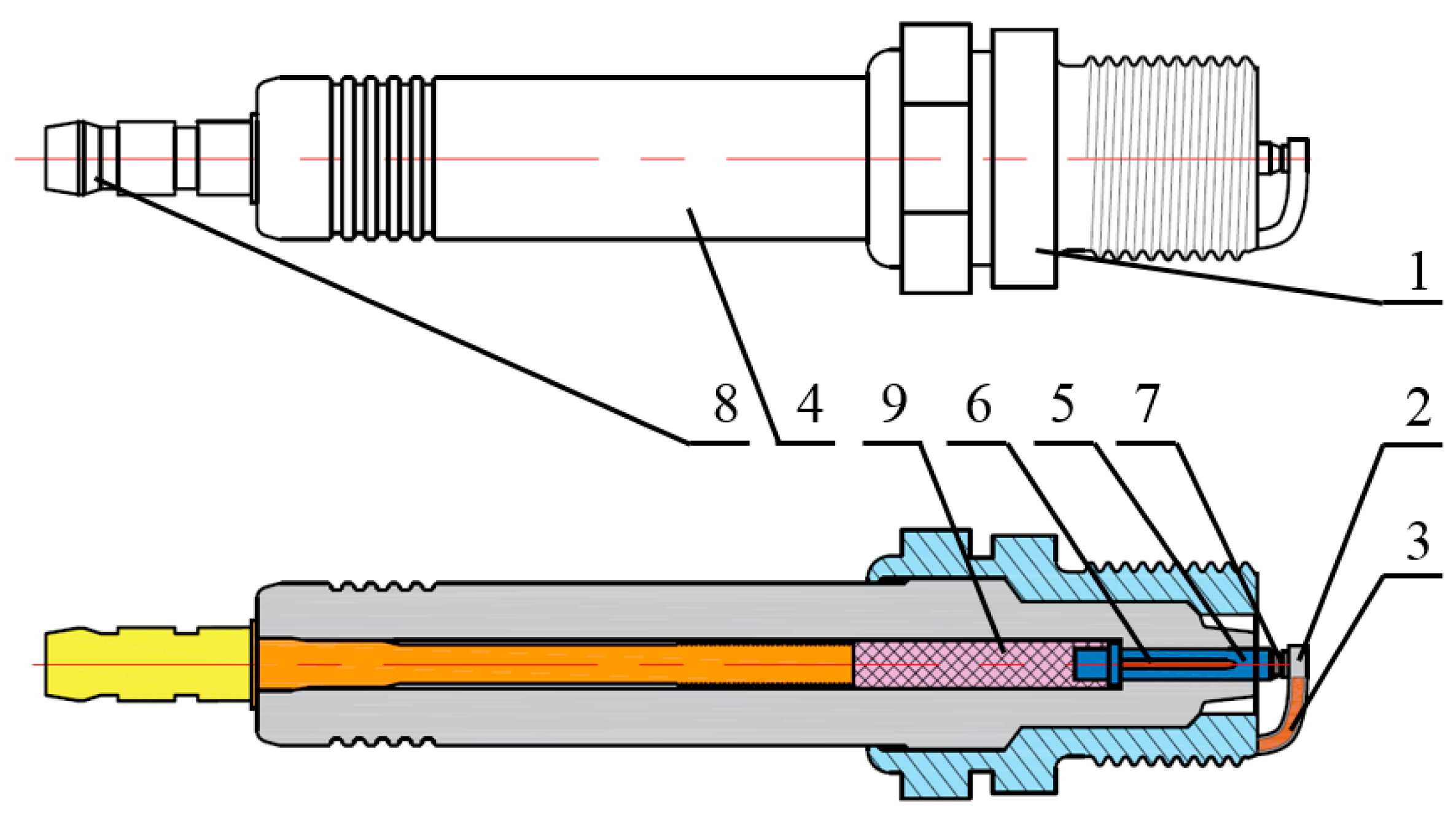
The basic components of a modern spark plug, shown in
Figure 1, include a spark plug body made of nickel–chromium steel (1). It is manufactured through plastic forming, which gives it its shape. A ground electrode (2) is attached to the body. Often, the ground electrode is made of two materials: a copper core (3) and a protective nickel–chromium steel jacket [
6]. The ground electrode is attached to the body by electrofusion welding [
5]. The body is attached to an electrical insulator (4), which is made of fine aluminum oxide powder. The powder is formed by pressing and then sintered and fired to give it its final shape and strength. Inside the electrical insulator is a center electrode (5), most often made of a copper core (6) encased in a nickel–chromium steel jacket. A small special insert made of durable material resistant to high temperatures and the current flowing during a spark discharge (7) can be attached to both the ground and center electrodes [
5,
6]. Electrical power is supplied from the high-voltage coil to the electrical connector (8). To reduce interference with other electronic devices, a suppression resistor (9) made of a graphite and glass mixture is used in the spark plugs [
7]. All these elements combine to form a spark plug, which then undergoes dimensional inspection, electrode gap adjustment, and high-voltage testing [
6].
The spark plug design shown is for illustration purposes only. Please note that spark plugs may have different designs, for example, multiple ground electrodes, different sizes, lengths, thread diameters, and electrode materials [
2,
4,
6,
8]. Currently, modern materials used for spark plug electrodes are characterized by the parameters presented in
Table 1. They are compared to the traditional spark plug material, nickel.
The use of modern materials for spark plug electrodes improved service life, but in the initial phases of research and production, it generated a number of problems [
11,
12]. One of these was the degradation of the Ni-Pt junction analyzed in [
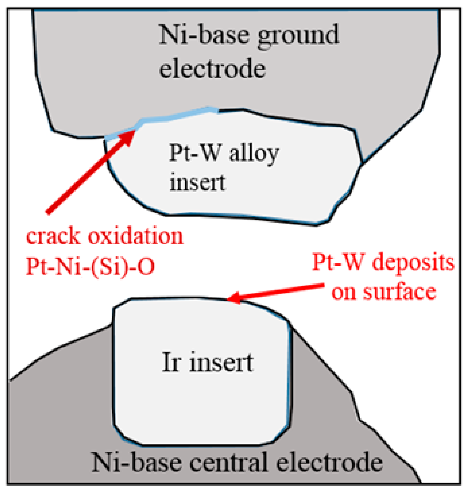
13]. Lin, H.T. and all observed, based on their experience with spark plugs in a natural gas-powered engine, that rapid degradation of this engine component occurs. SEM analysis of the electrode materials revealed a number of problems that significantly shorten the spark plug’s service life despite the use of modern electrode materials. The main difficulty they described was the degradation of the Pt-W and Ni junction. The SEM micrographs revealed a gap between the Pt-W alloy insert and the base Ni. Oxidation and cracking were observed along the length of the junction, ranging from 30% to 75% of the length (
Figure 2). The formation of Pt-Ni oxides and intense intergranular cracks were observed [
12,
13]. This phenomenon may be due to interdiffusion between the alloys during the production phase of these components. The second spark plug electrode was also made of the base material nickel, but the tip was made of iridium. In this case, the junction degradation was less severe. These defects may be the result of thermomechanical stresses occurring in the component during engine operation, as these materials have different thermal expansion rates [
5]. A crack at the interface between these two materials increases electrical resistance, requiring a higher voltage to breakdown and initiate an electrical spark [
13].
Another problem that modern spark plug manufacturers have had to solve is the improper connection between the core and jacket of the spark plug’s side electrode (alternatively called the ground electrode), which is attached to the body. The spark plug’s ground electrode features a copper core [
1]. Copper is not resistant to the factors that affect spark plugs, hence the need for a protective coating made of nickel–chromium steel [
2]. The copper core improves electrical parameters and better conducts heat to the plug housing [
2]. The ground electrode can be made of two materials and shaped through cold plastic forming, which creates the desired electrode shape [
6]. In the next production stage, the part is annealed at a high temperature of up to 1040 °C [
1]. The entire process is carried out in a gaseous environment containing hydrogen and nitrogen. After cooling in liquid nitrogen, the electrode is attached to the plug housing by resistance brazing [
6]. The final step is to shape the electrode into a “J” shape [
6]. During inspection, cracks were discovered on the outer surface of the ground electrode in a few products [
1]. After conducting tests and research, it was determined that eliminating this method would require moving the copper core beyond the resistance braze welding area, where it attaches to the spark plug housing. An alternative was to thoroughly clean the surfaces of both materials of oil, however this was too time-consuming and costly [
1].
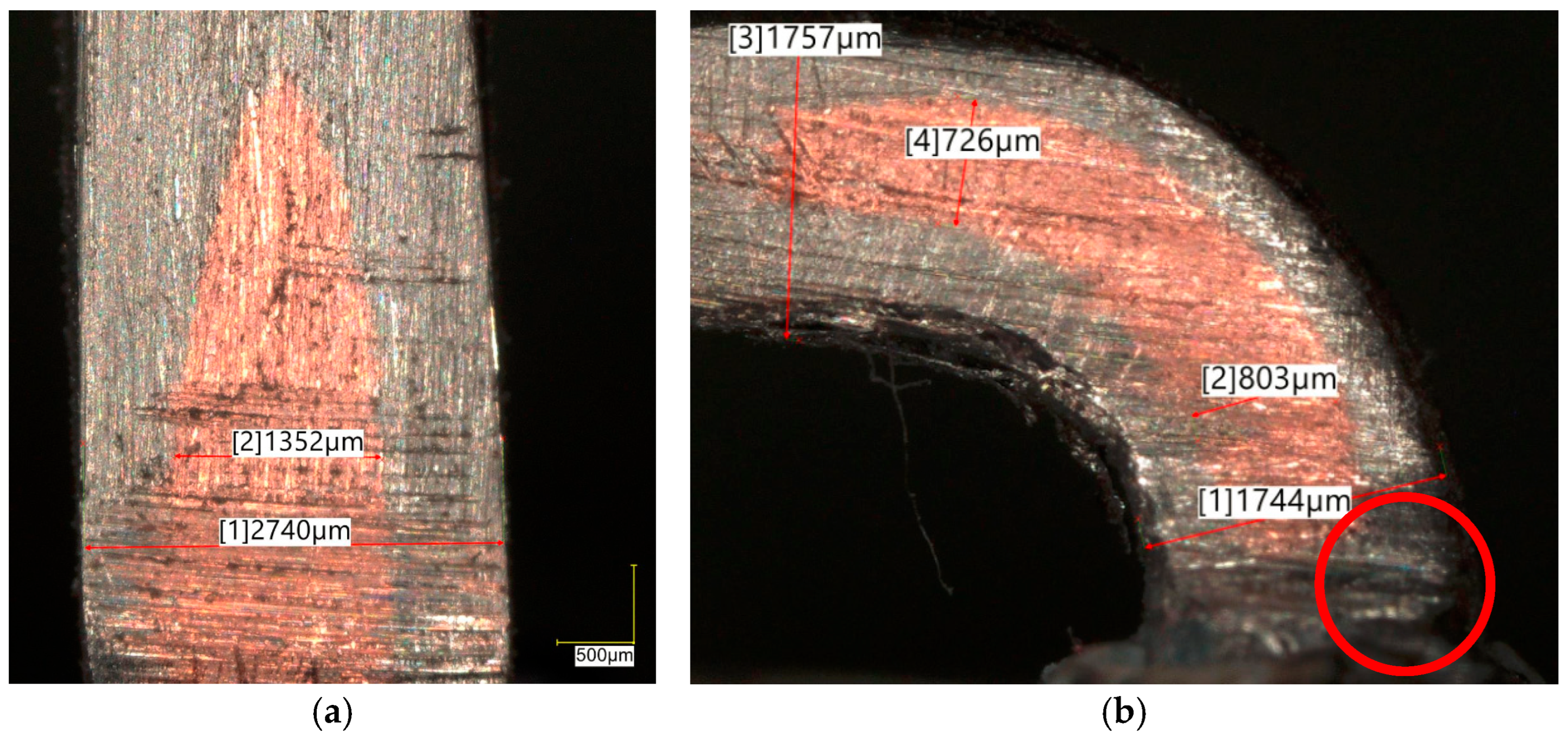
Figure 3 shows a cross-section of the central and ground electrodes with a visible copper core.
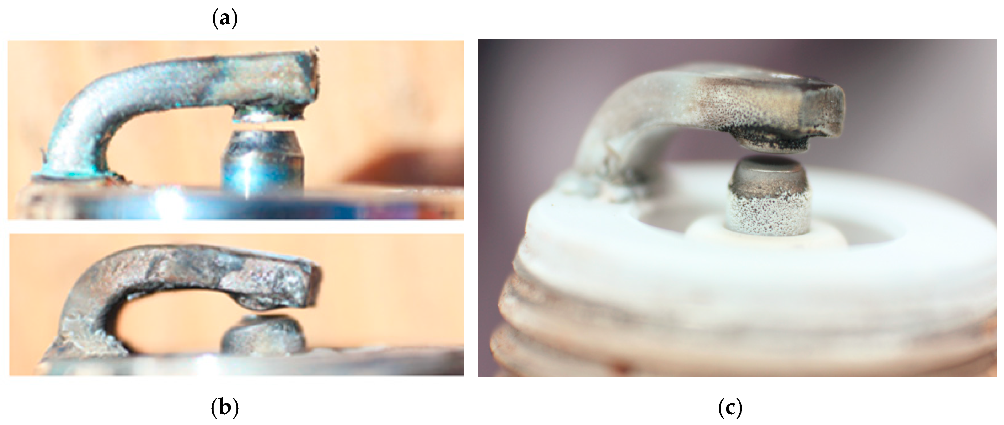
A spark plug is exposed to many harmful factors. Part of its surface is in direct contact with the combustion chamber, where it faces high temperatures during combustion, followed by cyclical cooling from the incoming fuel-air mixture, generating significant thermal stress [
11,
14]. The spark plug must also withstand the high pressure within the combustion chamber [
12]. The electrical insulator is required to resist voltages of up to 40,000 V [
11]. This electrical energy is converted into a spark between the electrodes, creating a plasma channel with temperatures reaching several thousand degrees Celsius. These conditions directly affect the spark plug electrodes [
15,
16]. Furthermore, the engine generates vibrations, for instance, from vehicle movement over uneven terrain [
4]. Another significant factor is the presence of aggressive combustion products, which accelerate the degradation of spark plug components [
4], as shown in
Figure 4.
During millions of engine cycles, repeated spark discharges occur between the spark plug electrodes. Each discharge consists of three distinct phases: the breakdown phase, where high voltage establishes a plasma channel; the spark phase; and the arc-glow phase. Throughout the latter two phases, electron emission from the electrode surfaces acts as a primary mechanism of spark plug degradation [
7,
17].
The literature identifies four mechanisms of spark plug electrode degradation. Among these, the particle ejection model describes erosion induced by a low-current electric arc. This arc locally heats the electrode material above its melting point, forming a molten pool. Ion bombardment then ejects the liquid toward the pool’s periphery. Upon the sudden cessation of the arc, surface tension drives the molten material back toward the center. If the resulting force is sufficiently high, a small volume of material is ejected from the electrode surface, where it is subsequently carried away by the ambient fluid flow [
18,
19]. An alternative model attributes material loss to evaporation at the cathode spot, where temperatures reach the boiling point. This concept excludes secondary chemical reactions, such as oxidation. Experimental data validate this mechanism, showing that electrode wear decreases as the boiling point of the electrode material increases [
20]. Another mechanism described is electrode degradation, which results from bombarding the material with ions that transfer their kinetic energy to atoms on the material’s surface. Under certain conditions, atoms can be ejected from the surface if the energy exceeds the binding energy [
19,
21]. One more mechanism suggests that spark plug electrode erosion involves the removal of oxides from the material, not the metal itself. Oxidation formation is necessary for significant electrode erosion. Rager Jochen et al. [
21] presented that a high melting point and resistance to oxidation of the material improve the durability of spark plug electrodes.
In the literature, besides models describing electrode degradation phenomena, there are few publications on spark plug operation in gas piston engines under real-world conditions. Existing studies on this topic focus primarily on comparing spark plug operating conditions depending on the fuel used and comparing the materials used for the spark plugs [
13,
16,
20]. Information regarding spark plug degradation remains scarce. For instance, in [
20], the description is limited to the electrode gap as a function of operating time, noting that as the distance increases, the voltage required to generate an electric arc also rises. The presented data cover various electrode materials (the center electrode was an Ir-Rh alloy and the ground electrode was a Pt-Ir-Ni alloy). Depending on the model, these can operate for between 1112 and 1400 h. Since the engine was fueled with natural gas, this information serves as a useful reference point, but for obvious reasons, it cannot be used for a direct comparison of results.
Based on available literature, a summary of selected factors affecting spark plugs was developed and is presented in
Table 2. Factors primarily responsible for spark plug degradation were identified. For comparison, these were evaluated against the conditions in an engine fueled with traditional gasoline.
Spark plug degradation is influenced by many factors, including the fuel used, excess air in the engine cylinder, and operating conditions. Did landfill gas cause faster spark plug degradation? How long can a spark plug operating in an combustion engine fueled by landfill gas? How does spark plug degradation occur? These questions motivated the research presented later in this article. A review of the available literature reveals a lack of comprehensive analysis regarding the degradation of modern spark plugs in engines fueled by landfill gas. This research gap is critical for both operators (in terms of engine life-cycle costs and replacement intervals) and service providers (concerning the frequency of adjustment and maintenance). These factors justify the present investigation into spark plug durability.
2. Materials and Methods
The experimental research was conducted at the Częstochowskie Przedsiębiorstwo Komunalne Sp. z o.o. waste management facility in the Silesian Voivodeship, Poland. In April 2025, a new CHP unit, featuring a spark-ignition reciprocating engine fueled by LFG, was commissioned to provide electricity and heat for the plant. Following a period of system fine-tuning, the initial test series was performed in the third quarter of 2025. The study focuses on spark plug degradation and its subsequent impact on CHP unit performance. The following sections provide a brief technical description of the system configuration before discussing the experimental results.
The CHP unit is supplied by a landfill gas collection station. The LFG treatment process begins with dehydration, where the gas temperature is reduced to remove moisture. The resulting condensate is then routed to a collection chamber. Subsequently, the gas is pumped through activated carbon vessels to adsorb contaminants and undesirable compounds, such as hydrogen sulfide and volatile organic silicon compounds (siloxanes). Following purification, the fuel is delivered to the CHP unit. The specific gas composition measured during the experimental period is detailed in
Table 3.
The CHP unit used for testing features a MAN E3268 (Nürnberg, Germany), an 8-cylinder Otto-cycle engine. The cylinders are arranged in a V configuration, with 4 cylinders arranged in each bank. The angle between the cylinder axes is 90°. The engine is specifically engineered for operation on LFG. LFG requirements include a methane content of at least 45%. The minimum calorific value must be 6 kWh/m
3 and a methane number of 140. Detailed unit specifications are presented in
Table 4. During the tests, original MAN 51.25923-0062 spark plugs (Nürnberg, Germany) were used. These spark plugs featured iridium electrodes on both the center and ground tips.
The CHP unit is housed in an insulated steel container, which provides environmental protection and acoustic attenuation. The engine draws combustion air directly from the container interior, which is maintained at positive pressure. Fresh air is supplied via an intake port equipped with a filter and a dedicated ventilation fan. During testing, the container ambient temperature ranged from 20 to 30 °C. The air–fuel mixture temperature in the intake manifold, downstream of the turbocharger and intercooler, was maintained at 50 ± 5 °C. System monitoring and control of both the engine and the LFG extraction process are integrated through a SCADA system and an HMI panel.
Engine operation is managed by an ECU, which, among other critical tasks, performs misfire detection [
25]. Misfires are identified based on instantaneous fluctuations in engine speed. A sensor monitors the flywheel teeth to record the intervals between successive pulses. An increased interval—indicating a drop in crankshaft velocity—signifies incomplete or absent combustion. The ECU aggregates these events within a 200-cycle measurement window. If the misfire count exceeds a predefined threshold, the system triggers an error and initiates an emergency engine shutdown [
25].
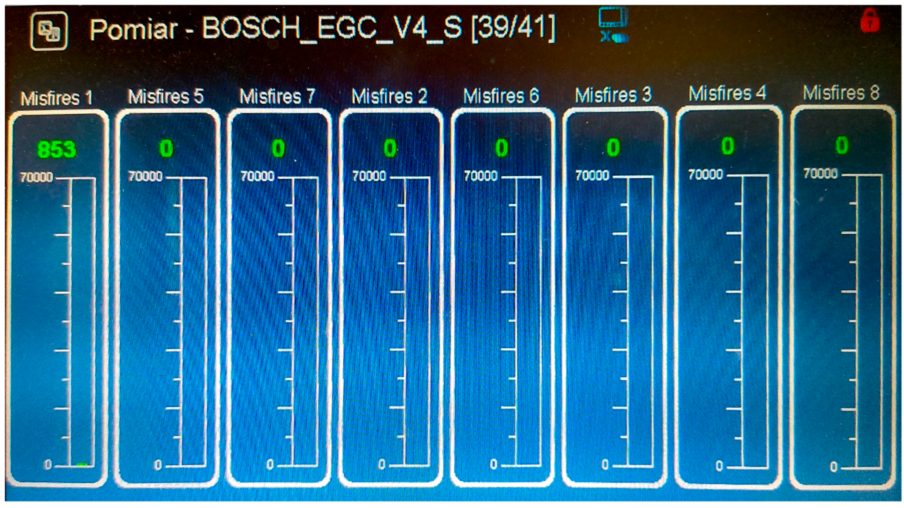
Figure 5 illustrates the misfire monitoring interface, where green values indicate the cumulative misfire count per cylinder since the last engine startup.
An alternative method for detecting misfires is ionization current analysis. This method involves applying a DC voltage to the spark plug and accurately measuring the current flowing between the spark plug electrodes after fuel combustion has completed. This current depends on factors such as combustion products, mixture composition, and impurities accumulated on the spark plug, and can provide information on whether combustion has proceeded correctly [
26]. The spark in the engine cylinder is generated once every two crankshaft revolutions, and the spark plug is idle for the remaining time [
17]. Therefore, the decision was made to utilize this additional engine component. This solution requires an additional electronic system that interfaces with the high-voltage system and is quite complex [
26]. Therefore, in an operational engine, the manufacturer chose crankshaft speed measurement as a source of information on the number of misfires.
The test engine was managed by a Bosch EGC4.0 ECU (Stuttgart-Feuerbach, Germany), specifically designed for gas-fueled engines in automotive and power generation applications. The ignition system, also by Bosch, utilizes a Coil-on-Plug configuration. Each cylinder is equipped with an individual Bosch 0281005862 ignition coil (Baden-Württemberg, Germany) mounted directly above the spark plug, thereby eliminating the need for high-voltage leads. This direct-mount design reduces secondary-side energy losses and electromagnetic interference.
3. The Results
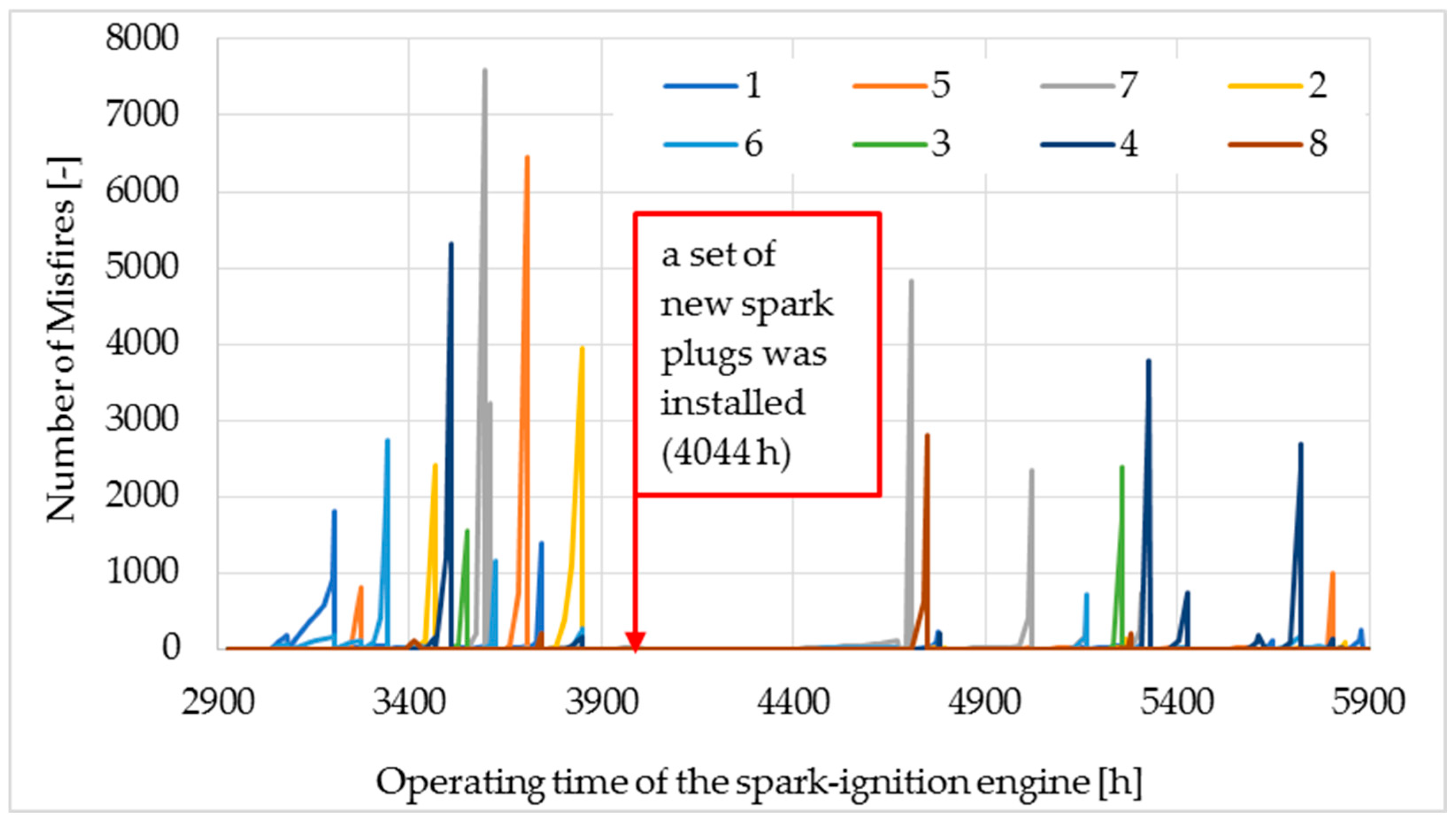
Based on the recorded number of misfires, important information about the condition of the spark plugs and engine operation can be obtained. The analysis covered 3000 h of operation of the CHP unit, presented in
Figure 6 (the CHP unit’s runtime corresponds to the operating time of the spark-ignition engine). The graph shows the number of misfires for each cylinder. This entire period can be divided into three intervals. The first covers the period from 2900 h to 4044 h, when the engine was operating with the most worn spark plugs. The second period covered the engine operation with a new set of spark plugs (4044 ÷ 4797 h). The third period (4797 ÷ 5900 h) saw the engine operating with spark plugs after the first adjustment (with moderately worn spark plugs).
When the engine is stopped due to the need to change the engine oil (every 500 h), the electrode gap of all spark plugs is also typically adjusted. This procedure was omitted after the new spark plugs were installed (4044 to 4797 h).
The ECU monitors misfire events by analyzing engine speed fluctuations derived from the flywheel sensor. For each cylinder, misfires are recorded cumulatively from the point of spark plug installation until its removal. If a spark plug triggers an emergency shutdown, it is replaced with a unit featuring a 0.2 mm electrode gap, cleaned surfaces, and a new sealing washer. Since the ECU misfire counters reset upon each engine restart, the total misfire count for each spark plug was determined by aggregating data across all recorded CHP operational runtimes. The calculated total misfires are presented in this paper.
What can be clearly observed is that during the first period of engine operation with severely degraded spark plugs, the number of misfires was high and frequent. This resulted in a large number of emergency stops. What is also noticeable is that engine shutdowns occurred at various maximum misfire values. In the second period, engine operation was exemplary in terms of additional maintenance work related to the ignition system. There were no emergency stops due to poor spark plug condition for 664 h. After this period, five emergency stops occurred due to significant deterioration of the spark plug electrodes. The final period required maintenance intervention due to several emergency stops. Although the spark plug electrodes were in good condition, emergency stops due to misfires still occurred.
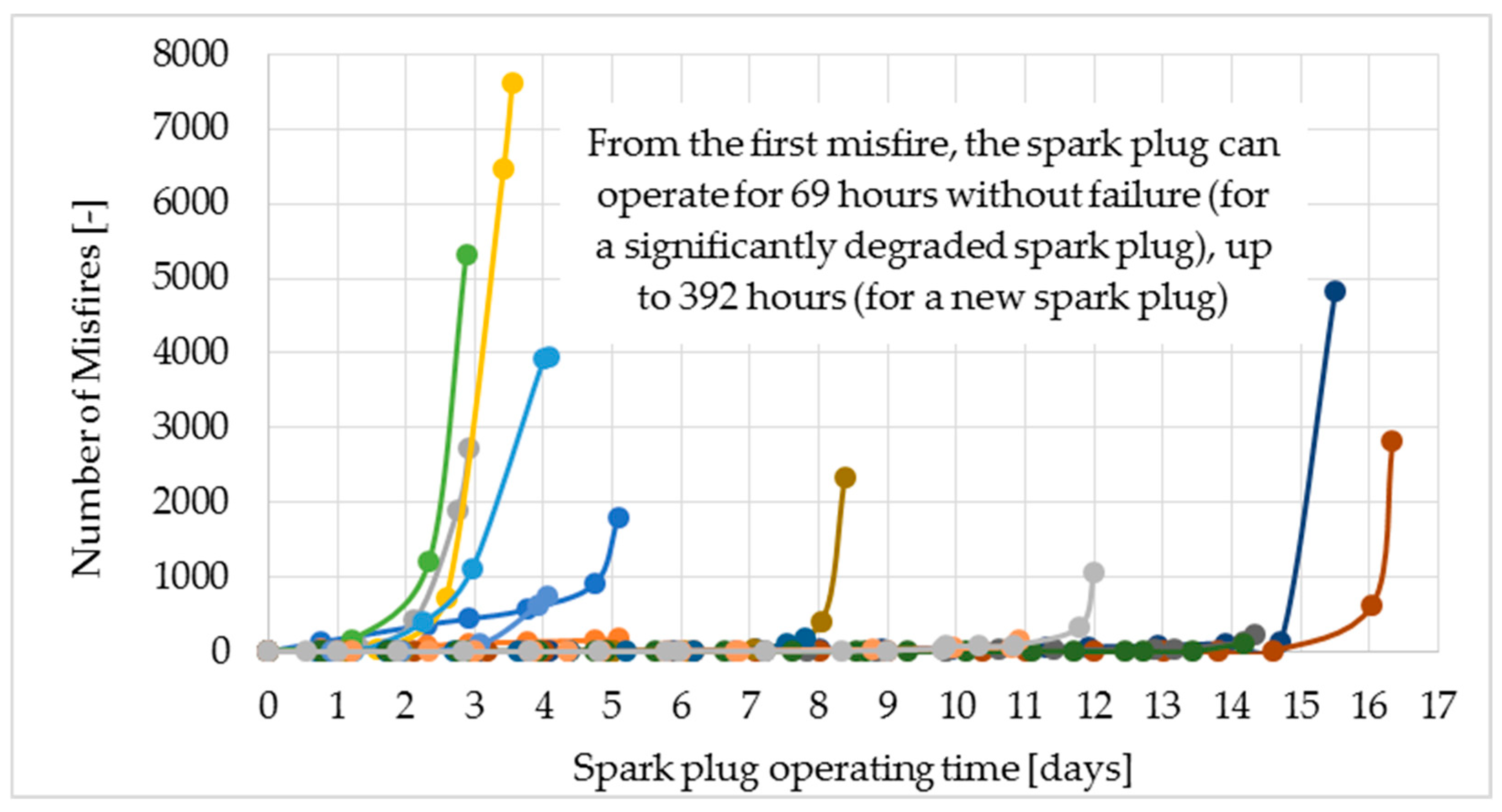
Arranging all the misfire count plots as a function of time to a single common point, the first recorded misfire, we obtain the graph shown in
Figure 7. The graph shows a large number of misfire counts on the left side of the graph, where the number of misfires increases to high values. These counts represent worn spark plugs. This is crucial information for maintenance, as from the moment the first misfires appear, the engine will likely stop within approximately 72 h. This is crucial because, as the weekend approaches, the unit is unattended, so the spark plugs must be in good condition to avoid an emergency engine shutdown. In such a case, the spark plugs should usually be replaced or adjusted on the last working day of the week, ensuring trouble-free engine operation for the following days. This problem does not occur when the engine is equipped with new spark plugs, as the engine can run for up to 15 days from the first recorded misfire.
Emergency engine shutdowns due to misfires were recorded across a broad range of cumulative values, specifically from 200 to 7623 misfires. If the misfire frequency within a single measurement cycle remains below the ECU threshold, the engine continues to operate, allowing misfires to accumulate over extended periods to a maximum recorded value of 7623. Conversely, if a high concentration of misfires occurs within a single cycle, the ECU triggers an immediate shutdown, displaying a misfires error and identifying the affected cylinder. This rapid-failure scenario was observed at cumulative totals as low as 200. It should be noted that the misfire counter resets upon each engine startup.
During the operation of the CHP unit, an analysis of spark plug electrode degradation was conducted. The analysis was performed on eight spark plugs installed in the engine at the same time. Original new spark plugs designed for the engine were used. The electrode gap was set to 0.2 mm, according to the technical documentation. A photo of the new spark plug is shown in
Figure 8. The spark plugs operated in the engine without any intervention from the operator for 664 ÷ 753 h. The difference in spark plug operating time results from the fact that the spark plugs operated in the engine until they caused an emergency engine shutdown due to numerous misfires. The average operating time of the spark plugs was 727 h. It should be noted that the technical data regarding engine operation states that the spark plugs should be adjusted every 1000 operating hours and replaced every 2000 operating hours. To better illustrate how many 727 h of work is, you can easily convert it to the distance traveled by a vehicle traveling, for example, at an average speed of 50 km per hour. Multiplying these two numbers yields 36,350 km, which is a significant distance. However, this service life is several times shorter than that of iridium spark plugs used in automotive engines [
2]. Additionally, it has a shorter service life than the spark plugs used in natural gas engines [
20].
Spark plug degradation was evaluated using a Keyence VHX digital microscope (Osaka, Japan). This high-precision system enabled comprehensive dimensional measurements of both the ground and center electrodes before and after engine operation. The resulting data were used to calculate the volumetric loss of electrode material. Following the microscopic analysis, the spark plugs were prepared for reinstallation to undergo further testing.
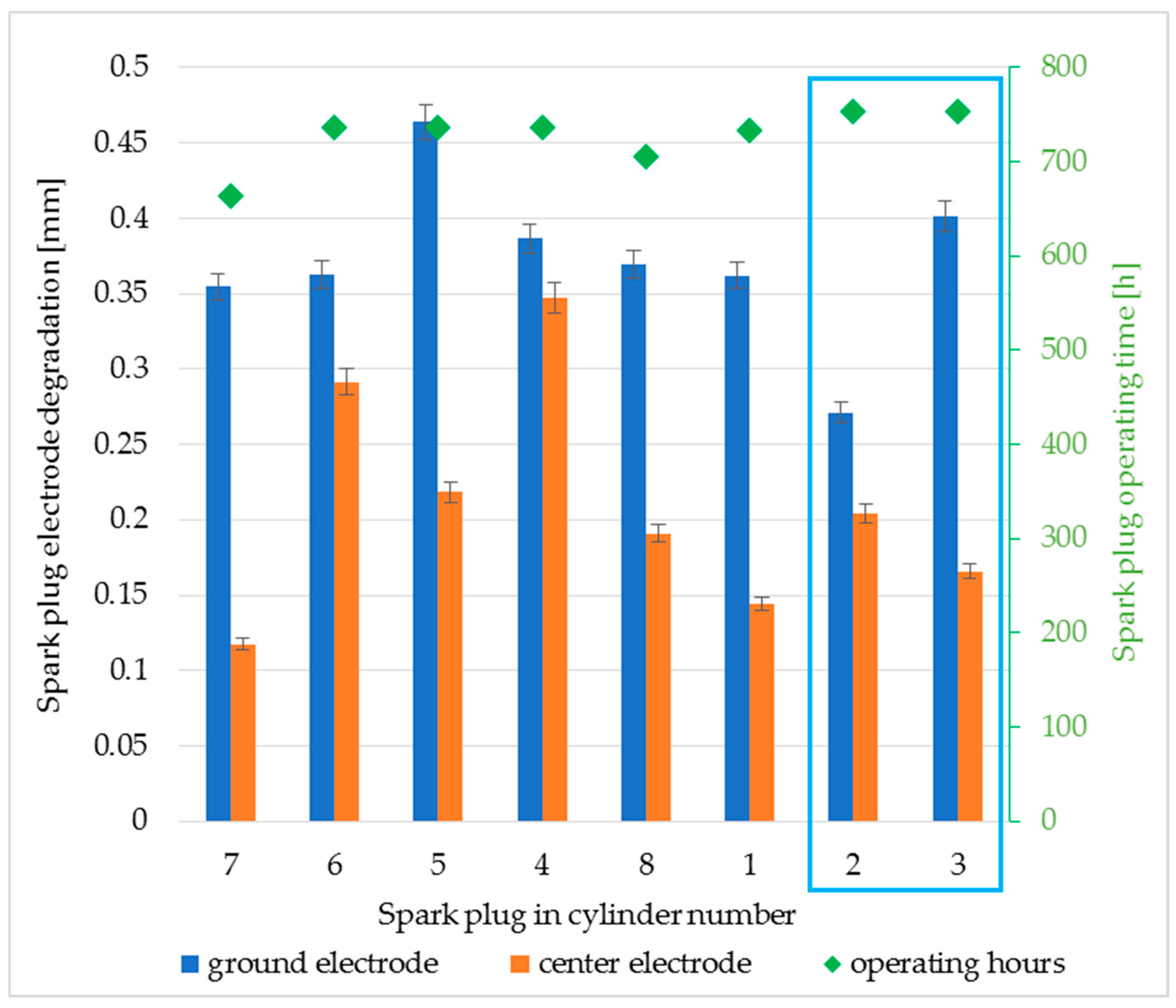
Spark plug degradation was quantified by measuring the material loss from both the center and ground electrodes. For each spark plug, greater degradation was observed for the ground electrode compared to the center electrode (
Figure 9). Ground electrode wear ranged from 0.27 mm to 0.46 mm, while center electrode wear ranged from 0.12 mm to 0.35 mm. Calculating the average values for eight spark plugs yielded a degradation of 0.37 mm for the ground electrode and 0.21 mm for the center electrode. Increased wear of the ground electrode spark plug on cylinder number five may be because the electric arc was directed towards the ground electrode, which caused its temperature to increase and, consequently, increased wear [
21,
23,
27]. The spark plugs installed in cylinders 2 and 3 operated the longest. Only these spark plugs did not cause an emergency engine shutdown, while the other six did (that is why they are marked with a blue frame in the drawing). Spark plug adjustments and an assessment of their technical condition were performed during a scheduled engine service.
Following the maintenance schedule, all spark plugs underwent adjustment by an authorized service center at 4797 total operating hours. The service included resetting the electrode gaps to 0.2 mm, removing surface deposits, inspecting the threads, and installing new sealing washers. After a further 214 h of operation, the first emergency engine shutdown was triggered by a misfire in cylinder no. 7. The frequency of subsequent shutdowns increased significantly compared to the initial period.
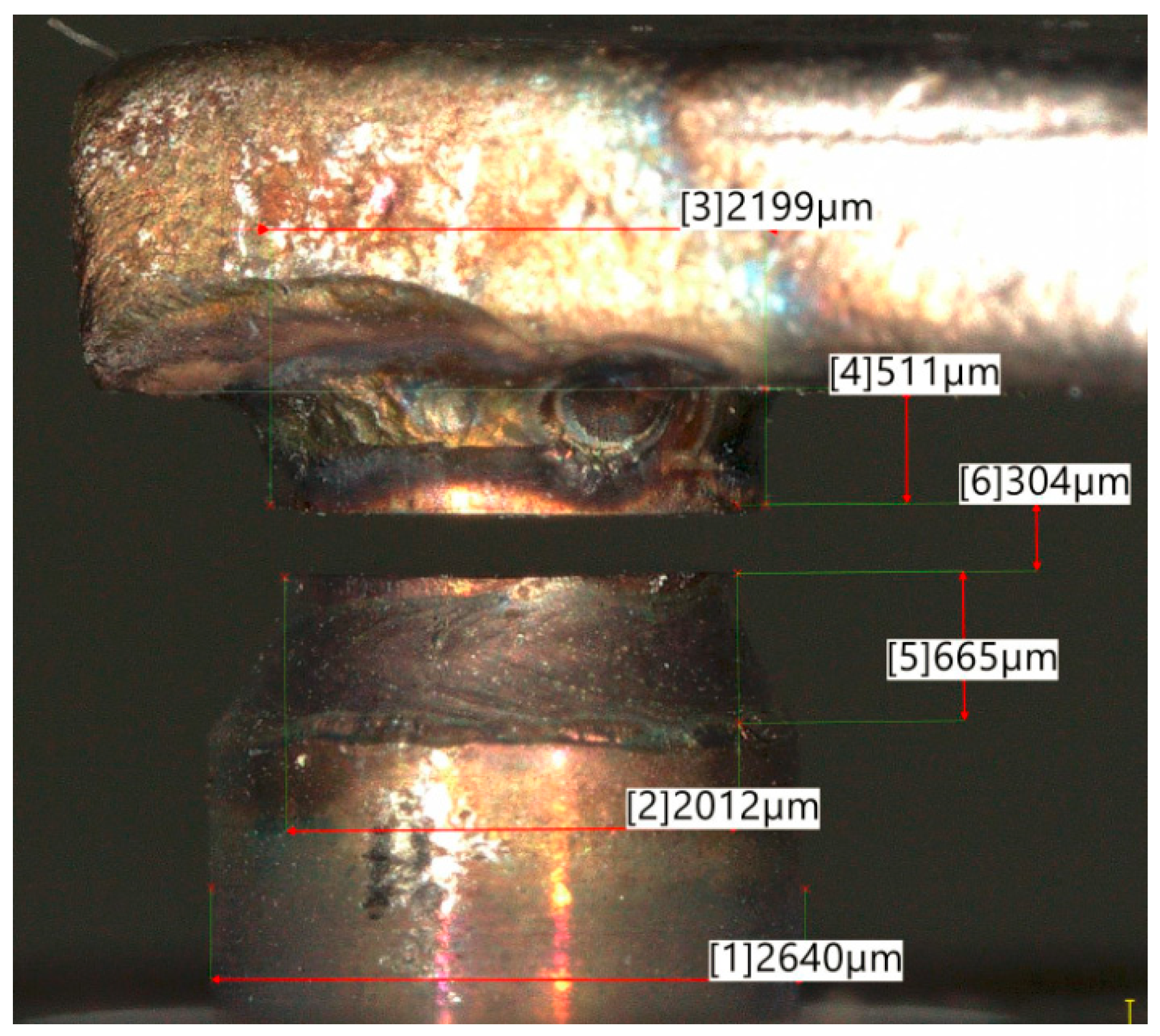
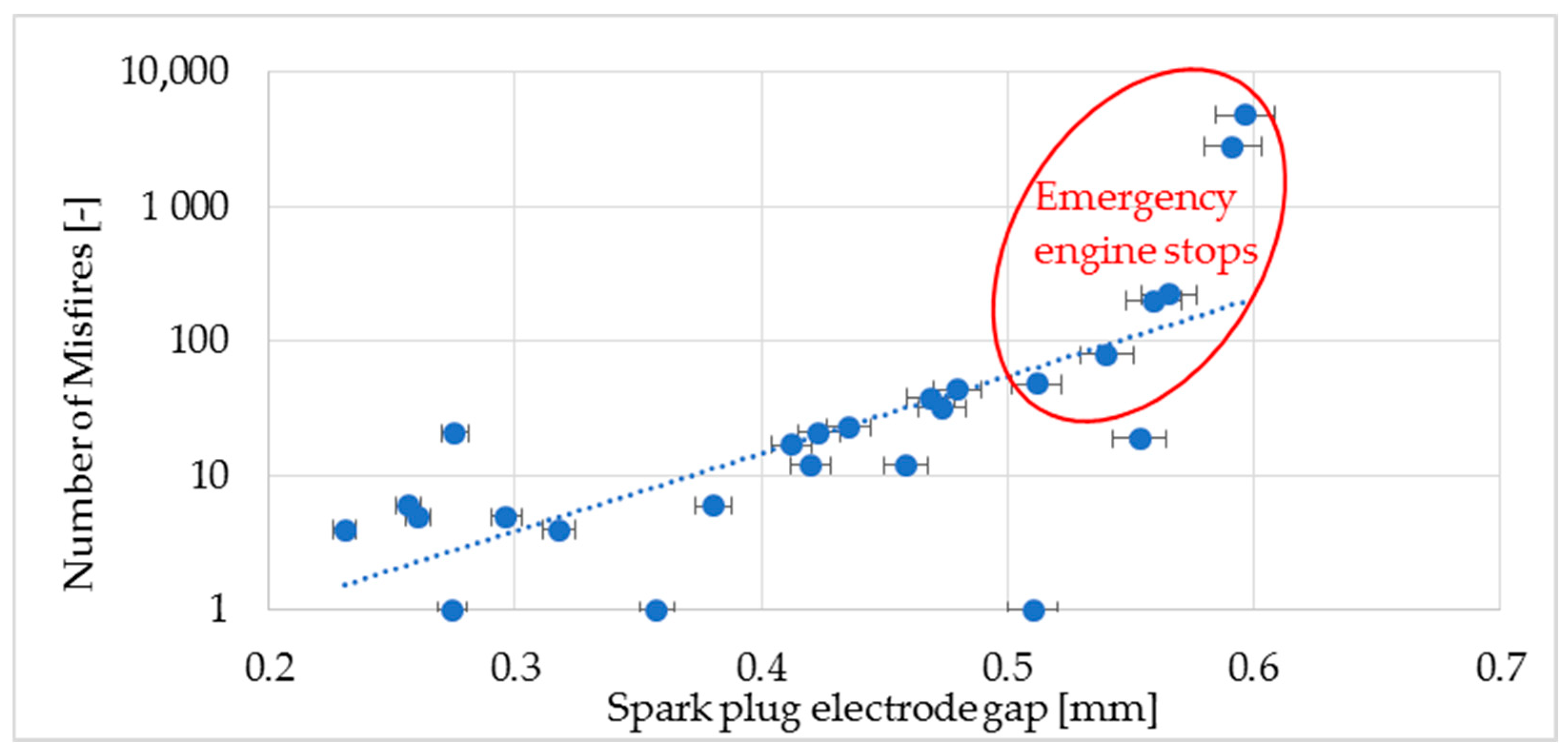
The main consequence of electrode degradation is an increase in the gap between the electrodes, which leads to improper ignition of the mixture in the engine’s combustion chamber. Based on the collected data, a correlation can be observed between the number of misfires and the gap between the spark plug electrodes, as shown in
Figure 10. The initial gap value is 0.2 mm, but even a small increase in the gap causes isolated misfires. As the gap between the electrodes increases, an increase in the number of recorded misfires can be observed. For a gap of 0.5 mm or greater, engine shutdowns due to an excessive number of misfires have been recorded during engine operation. Individual misfires are harmless; the engine controller records them, but they do not affect subsequent engine operation. The largest recorded gap between the spark plug electrodes was 0.6 mm. For comparison, in gasoline-powered automotive engines, the recommended gap is 0.6 mm [
2]. In the case of a CHP unit, such a gap will certainly cause an emergency engine shutdown. An emergency engine shutdown caused by misfires is closely related not so much to the total number of misfires as to their rate of increase. The permissible number of misfires in the time window of the measurement cycle can be up to several percent, and this is the limit value beyond which a failure is signaled [
25]. This value results from the fact that unburned fuel enters the exhaust system, where it can increase the temperature of the catalytic converter, potentially causing permanent damage. The second reason for measuring misfires is the requirement to meet stringent regulations regarding exhaust emissions [
25]. If the engine is operating incorrectly, toxic exhaust emissions increase. Regulations require the engine to be stopped. The decision to shut down the engine is made by the controller based on the number of misfires.
Misfires are monitored individually for each ignition system in real-time. In the tested engine, this parameter enables the assessment of spark plug condition and combustion stability without requiring operational intervention or engine shutdown. Although exhaust gas temperature is another indicator of combustion quality, the collective measurement across all cylinders makes it impossible to identify a faulty specific ignition system. The monitoring system is based on two key metrics: the cumulative misfire count and the misfire rate. While the ECU only displays the instantaneous counter value on the HMI panel, a predictive maintenance approach was implemented by correlating these readings with total engine operating hours. This correlation provides high accuracy in predicting potential emergency shutdowns.
In the final hour preceding the emergency shutdown, the misfire rate accelerated to a peak of 400 events per hour. Given that the engine operates at 45,000 cycles per hour, this maximum rate corresponds to a misfire frequency of approximately 0.9%. This rapid escalation serves as a critical indicator of imminent spark plug failure.
By monitoring the number of recorded misfires for each spark plug and correlating it with its operating hours, it is possible to make informed decisions regarding maintenance (adjustment or replacement) before an emergency shutdown occurs. This approach aims to prevent unplanned engine downtime and ensures that maintenance activities are performed while personnel are available on-site (technical staff are not present during afternoon and night shifts). If the misfire count exceeds 100 and has increased by more than 10 in the last hour, service action is recommended. These procedures were implemented following the conclusion of the research to optimize operational reliability.
The spark plug electrode gap has a key impact on the occurrence of misfires. The measured electrode gap, shown in
Figure 10, is the minimum distance between the center and ground electrodes. The electrodes wear unevenly, and the gap between the surface is tapered. The increased electrode gap during spark plug operation necessitates a higher breakdown voltage to initiate the electric arc [
20]. The implemented ignition coil effectively generated the required discharge to ignite the air–fuel mixture, achieving clearances of up to 0.6 mm.
Misfires may also originate from malfunctions in the ignition system or the engine speed sensor, which controls critical parameters such as ignition timing. To isolate the cause of the observed misfires and exclude potential ignition system failure, a new set of spark plugs was installed upon completion of the test series. Following this installation, the engine operated continuously for several days without an emergency shutdown, and the misfire count for all cylinders remained at zero. These results confirm that the previously recorded misfires were attributable solely to spark plug degradation rather than ignition device system faults.
The volume of degraded material is calculated using volumetric relations based on the measured reduction in height and the known diameters of the electrodes. Further analysis determines the specific wear per spark. Since the ground electrode has both a larger diameter (2.2 mm vs. 2.0 mm) and a higher erosion rate than the center electrode, significant differences in specific wear are observed between the two. Specific spark plug wear is the average degradation of a new spark plug from installation until its first removal. To calculate this value, divide the plug’s volumetric degradation by the total number of spark discharges recorded during its operation.
The engine in the CHP unit operates at an engine speed of 1500 rpm. Due to the fact that it is a four-stroke engine, the number of sparks that cause spark plug degradation is half as large, at 750 sparks per minute. For each spark plug, the number of ignition sparks and operating cycles is calculated individually. The average number of sparks from the analyzed sample is approximately 32.7 million sparks. Specific wear of the center electrode ranges from 11.8 µm
3/spark to 31.60 µm
3/spark. The average value for the set of eight spark plugs is 19.28 µm
3/spark. Specific wear of the ground electrode ranges from 32.08 µm
3/spark to 56.10 µm
3/spark. The average value for the set of eight spark plugs is 45.60 µm
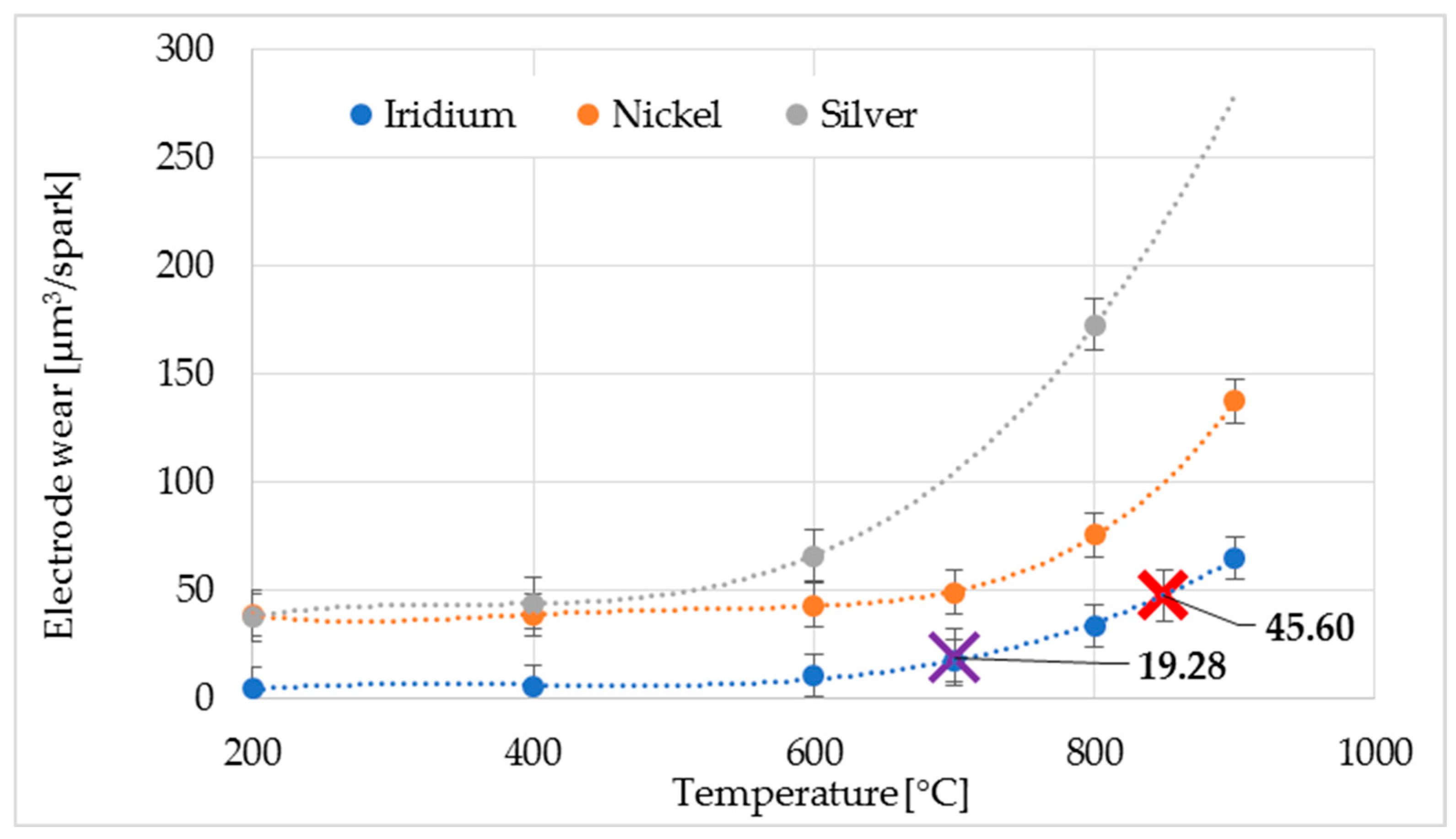
3/spark. Using a spark plug with iridium inserts allowed the engine to operate for the specified time. Using traditional spark plugs with nickel electrodes would have resulted in faster electrode degradation, and maintenance-free operation would have been halved [
21]. The specific wear for the center and ground electrodes is shown in
Figure 11. The authors [
21] conducted research presenting the relationship between the effect of temperature on spark plug electrode wear, which was used in this analysis.
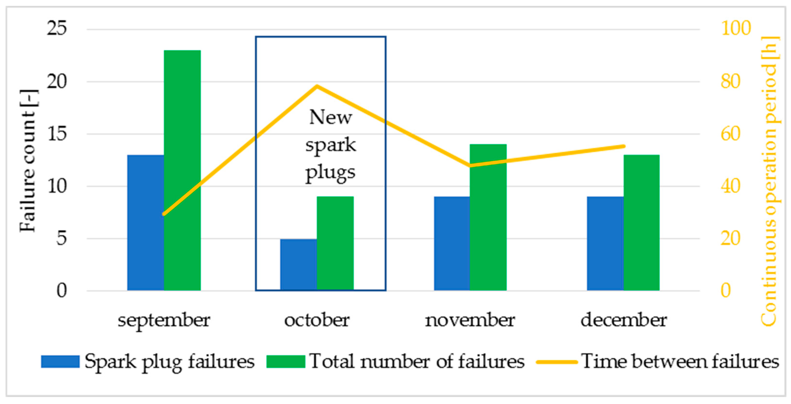
A very high availability parameter characterized the CHP unit’s operation. During the analyzed period, the engine operated 93 ÷ 97% of the time. The maintenance staff demonstrated a professional approach in this regard, resulting in such high rates combined with a high number of emergency shutdowns. In the initial period, when the system operated with severely degraded spark plugs, 23 emergency shutdowns were recorded, 13 of which were caused by improper operation of the ignition system and specifically the spark plugs. The number of misfires increased on subsequent cylinders, always resulting in an emergency shutdown of the engine. Breaking down the analyzed period by month,
Figure 12 shows that after replacing the spark plugs with a new set, the number of failures caused by the ignition system decreased from 13 to 5 compared to the first month. Furthermore, the unit’s continuous operation period increased. In the first month, the engine stopped on average every 29.61 h, and in subsequent months, this indicator peaked at 78.33 h for the new set of spark plugs. With further operation, the average time between stops was 48.07 h and 55.53 h. In the following months, the downtime was 40 h, 39 h, 47 h, and 22 h, respectively. In this case, there is no dependence or correlation with the condition of the ignition system, because it is influenced by many factors, including service work on the engine, service work on the fuel treatment system, work on the gas pipeline, and work on the power grid.
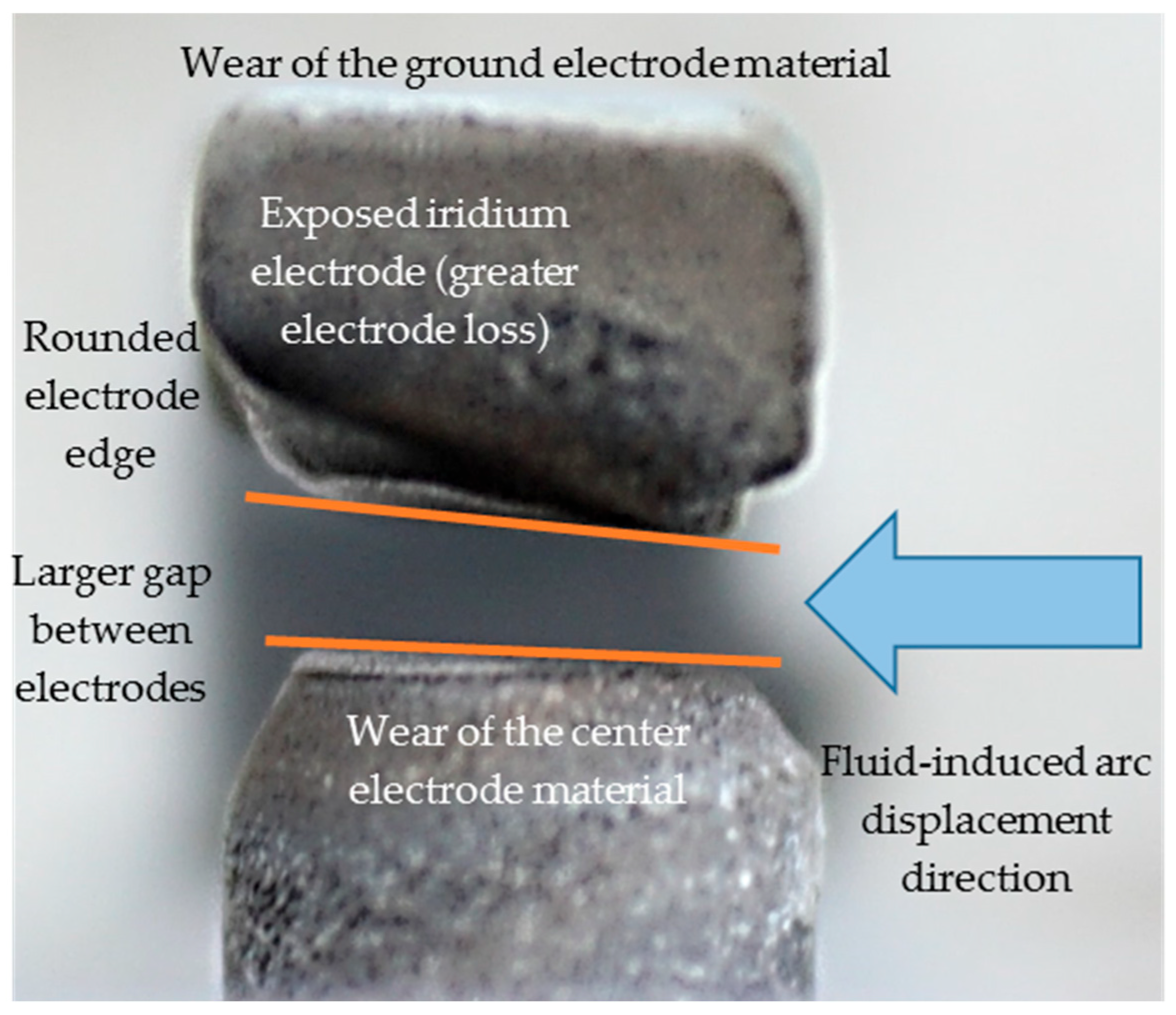
Spark plug degradation varied depending on the cylinder, but the following common features were observed: Spark plug electrode degradation is uneven. Each spark plug shows fragments of more severely degraded surfaces. Electrode degradation was characterized by rounded edges of the electrode and loss of electrode face surfaces (
Figure 13). The location of increased spark plug electrode degradation may be strongly related to the direction of fluid flow around the spark plug, which causes the electric arc to move toward the electrode edges [
15]. This phenomenon was repeatable, as electrode degradation was observed in a single location. The second phenomenon resulting from the spark plug being exposed to a fuel-air mixture is the elongation of the electric arc [
18]. The effects of this phenomenon can be recorded and observed on the voltage graph on the secondary winding of the ignition system, which manifests itself as sudden voltage spikes during the arc ignition phase [
17,
18].
Spark plug performance and misfire frequency in gas engines are significantly influenced by auxiliary ignition components, including spark plug caps, ignition coils, high-voltage leads, the electrical system, and ECU [
17]. To isolate the spark plug condition as the primary variable, the impact of these components was standardized across all test groups as follows: all spark plugs were powered by OEM ignition coils sharing identical part numbers, performance characteristics, and identical operating hours. High-voltage wire interference was eliminated by utilizing a coil-on-plug configuration. Furthermore, the ECU’s integrated diagnostics monitored for anomalies in current, charging time, and voltage [
25]; however, no system failures were recorded during the test.
Post-test verification, involving the installation of new spark plugs, resulted in several days of stable operation with no increase in misfires. These results confirm that, in the analyzed case, the condition of the spark plug is the decisive factor in misfire occurrence, while the ignition system remained fully functional throughout the experiment.
It should be noted that the degradation or failure of ignition coils and high-voltage leads can significantly increase misfire frequency. Deterioration of high-voltage leads primarily involves insulation breakdown and a subsequent decrease in insulation resistance. This results in a voltage drop at the spark plug electrodes, leading to frequent misfires or, in extreme cases, sudden engine stall. Similar effects occur when ignition coil windings suffer from insulation damage [
17].
Diagnostic procedures in such instances typically involve component swapping (cross-testing) between cylinders. By transferring a suspected component to a functional cylinder and observing if the fault follows the part, the defective unit can be accurately identified. Furthermore, gas engine ignition systems vary in design and specification. Differences in peak voltage and spark energy can significantly impact spark plug performance and service life [
17,
20].
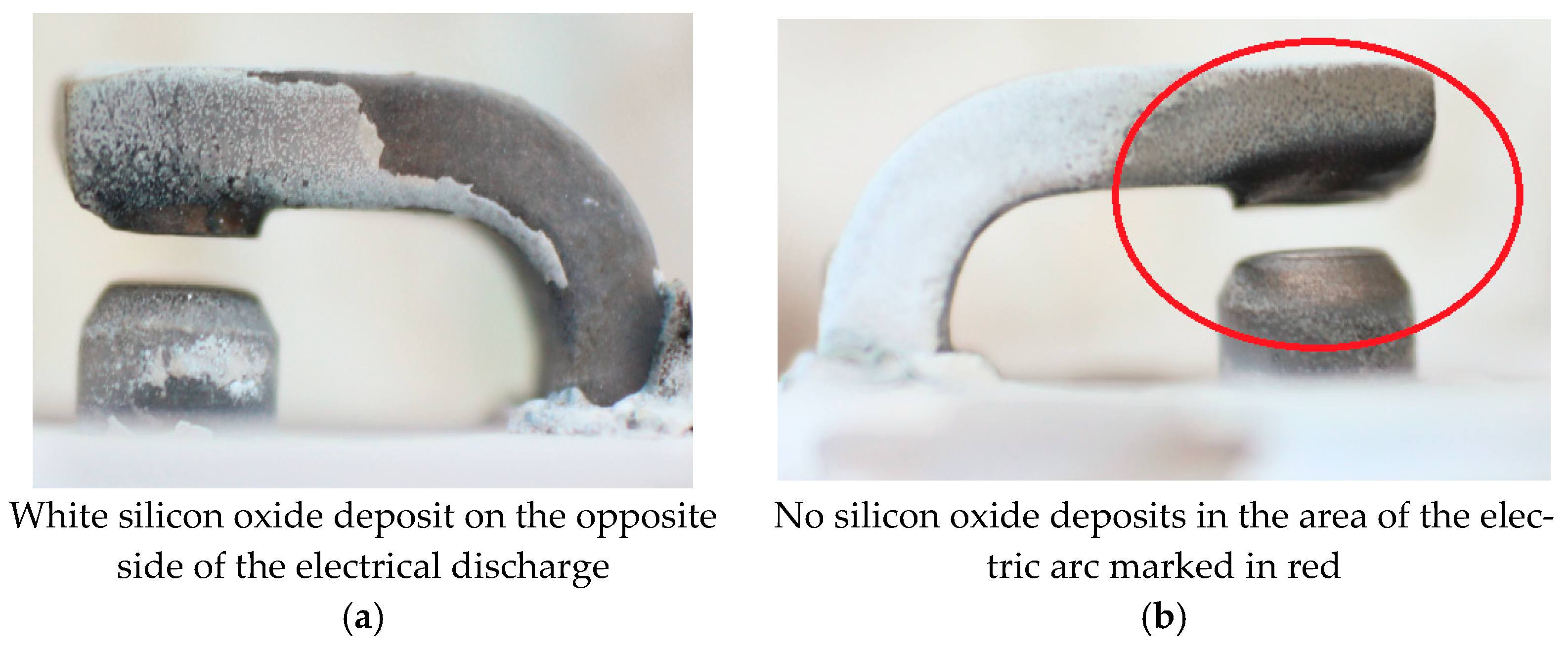
A solid white coating, shown in
Figure 14, could be observed on the spark plug surfaces. This coating is silicon oxide deposit. Volatile silicon compounds enter the engine along with the fuel. These compounds oxidize to SiO
2 compounds at high temperatures during fuel combustion, which then deposit on cool engine surfaces, including the spark plug [
28].
A white coating on the spark plug is the first symptom indicating the need to replace the activated carbon in desulfurizers, which can also trap volatile silicon compounds [
28]. A white deposit was observed during the final testing phase, appearing after 5000 h of operation. The white coating is harmless to ignition system components. The compounds are removed near the electric arc and on the electrodes, where temperatures are high. White deposits, however, are very dangerous for the engine because they can cause seizure of the piston and engine cylinder [
28].
During inspection of the spark plug electrodes, small craters were observed on the edge of the center electrode. These may be the result of degradation resulting from intense electrical discharges between the electrodes. During sparking, a plasma channel is created, characterized by very high temperatures, which may be responsible for the occurrence of phenomena such as those shown in
Figure 15 [
7].
The appearance of more visible craters on the center electrode is caused by the direction of current flow. During a spark discharge between the spark plug electrodes, the current has a constant direction [
29]. A higher potential is applied to the center electrode, and it is to this surface that electrons, concentrated in a point, move [
11]. The locally intense energy transfer causes an increase in the electrode material temperature, resulting in intense local degradation of the electrode material. Because the electric arc moves in one direction, the arc persists longest at the electrode edges, where increased material loss occurs [
22].
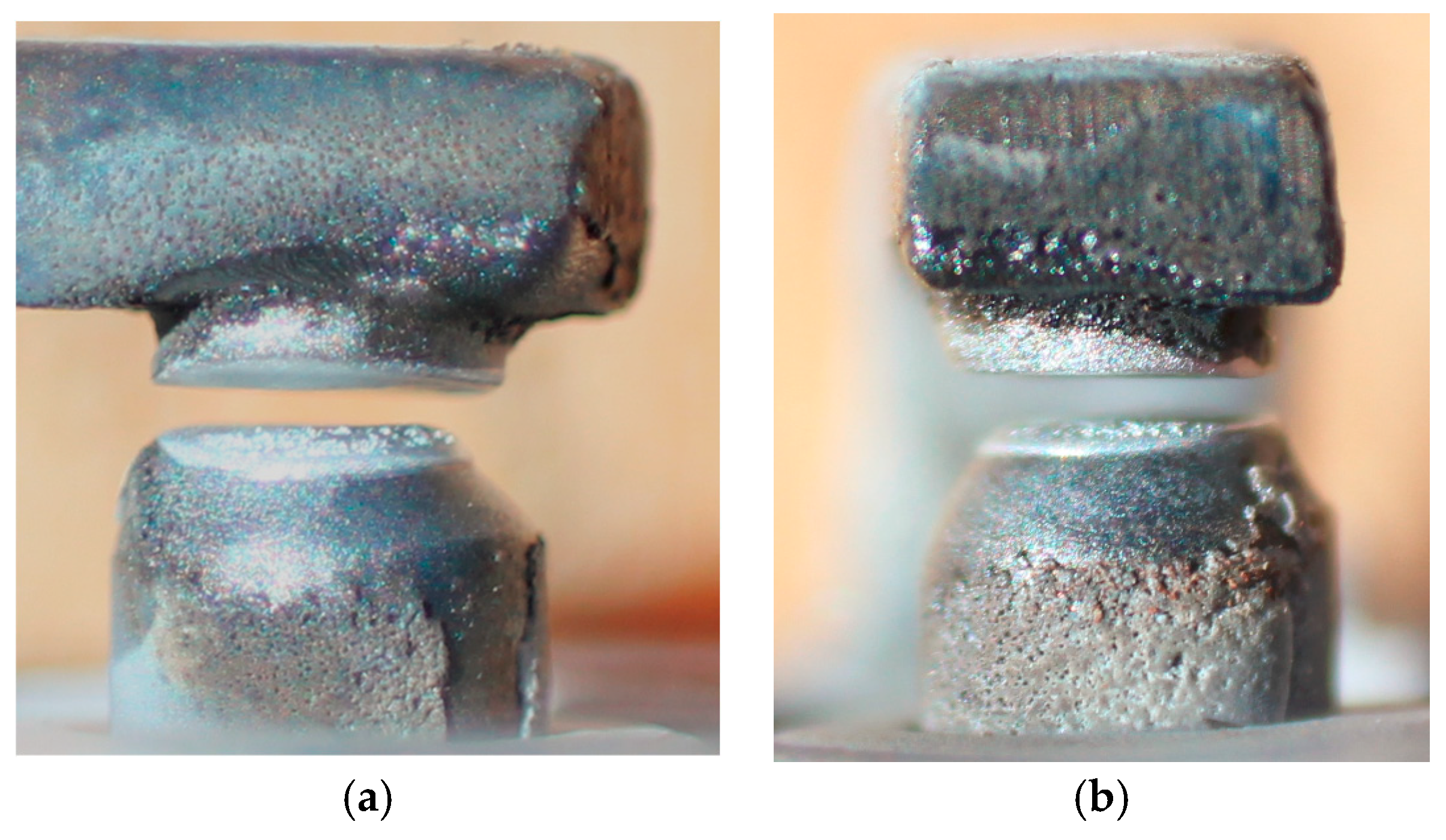
The faster degradation of the ground electrode is confirmed by
Figure 16, which shows the absence of an iridium plate in the ground electrode, while an iridium element is visible in the center electrode. Considering only the visible portion of the iridium plate and the wear calculated based on the conducted tests, it can be estimated that the spark plug could operate for approximately 1680 h, but due to the lack of an iridium insert in the ground electrode, further operation is impossible. Using such a spark plug requires frequent shutdowns of the CHP unit and adjustment of the spark plug electrode gap, which is uneconomical and cumbersome. Each unit of downtime causes losses for the company. Therefore, it is important to change the spark plug design to ensure longer service life.
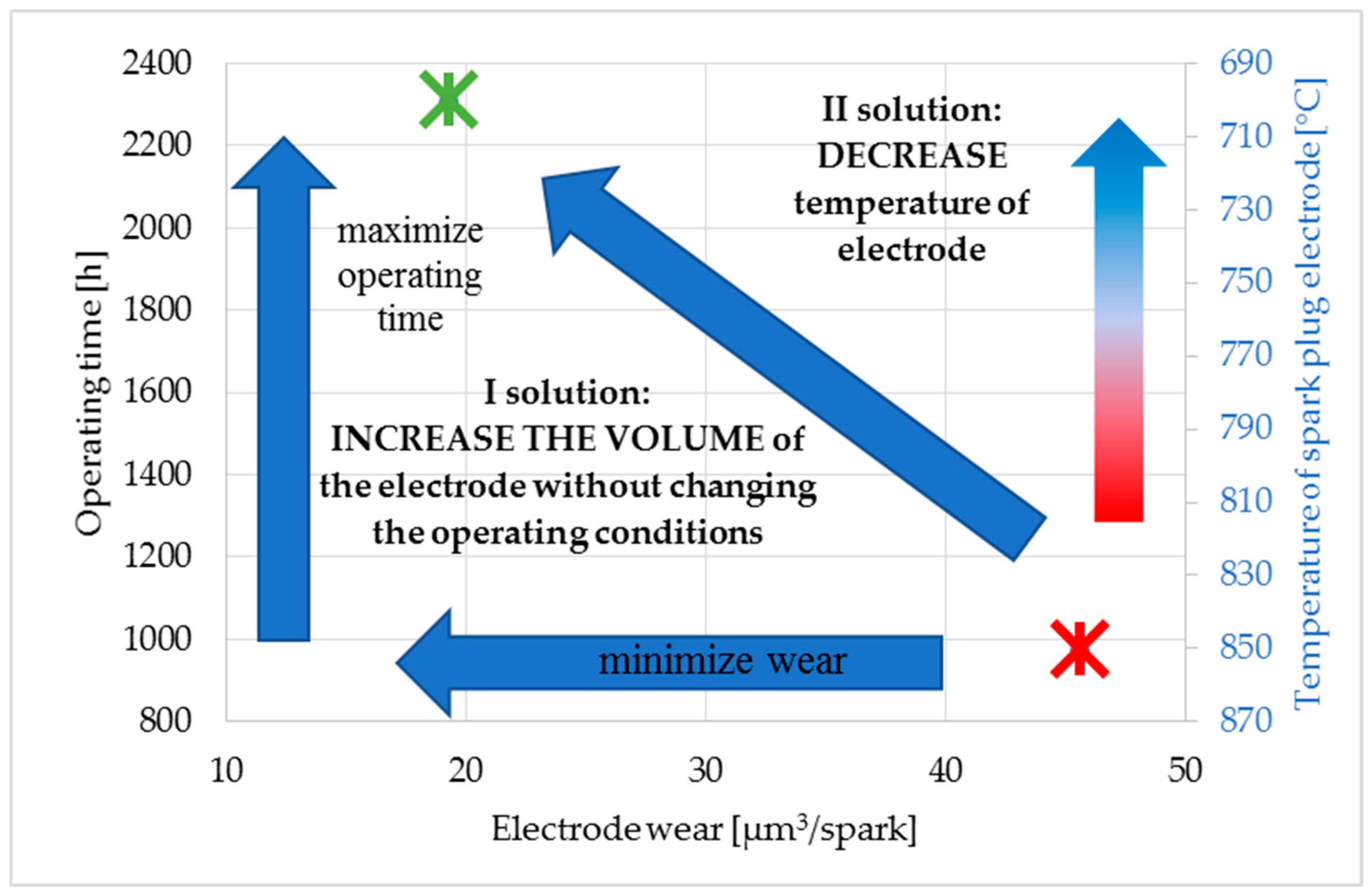
To extend spark plug life, special attention should be paid to the ground electrode, as it determines the suitability of the spark plug. To extend the life of the spark plug, take the following steps, as shown in
Figure 17. The first method involves increasing the volume of the ground electrode material. The second way to improve spark plug life is to reduce electrode wear. To reduce wear of this component, the first step is to lower its operating temperature [
27]. Proposed design improvements for reducing electrode operating temperature and mitigating wear are discussed below.
The first method for increasing service life is relatively straightforward to implement, as it only requires enlarging the electrode, for example lengthening the ground electrode. In contrast, the second solution is more complex, necessitating further experimental research and theoretical analysis. Mitigating thermal effects on the ground electrode by modifying its shape and dimensions significantly impacts flame propagation. Consequently, simulations and experimental studies are essential to determine how these design changes influence flame front development and fuel combustion [
8,
27,
30]. These issues will be the focus of subsequent analyses, with the results to be presented in future publications.
A third method for extending spark plug life is to change the electrode tip material [
31]. The use of iridium significantly extended spark plug life compared to traditional nickel spark plugs. For LFG fueled engines, spark plug life is short, which may be an additional motivation for further investigation into potential alternative materials for spark plug electrode tips. Research is currently underway into the use of other electrode materials, such as ceramic sintered electrodes and iridium additives, to extend service life [
31]. This solution to improving spark plug durability could be interesting given the limited amounts of iridium available and its widespread use in various sectors of modern industry. Further experimental research and simulations are necessary to determine the optimal solution. The proposed designs and the presented operational test results may inspire further development in spark plug engineering to extend service life.