Article

Comparative Study on Continuous and Discrete Design Optimization for the Fairlead Chain Stopper of Large-Scale Floating Offshore Wind Turbines

1
Department of Naval Architecture & Ocean Engineering, Mokpo National University, Muan-gun 58554, Jeonnam, Republic of Korea
2
School of Mechanical & Ocean Engineering, Mokpo National University, Muan-gun 58554, Jeonnam, Republic of Korea
*
Author to whom correspondence should be addressed.
Energies 2026, 19(8), 1893; https://doi.org/10.3390/en19081893
Submission received: 1 February 2026 / Revised: 14 March 2026 / Accepted: 10 April 2026 / Published: 14 April 2026
(This article belongs to the Special Issue Latest Challenges in Wind Turbine Maintenance, Operation, and Safety)

Abstract

This study presents a comparative investigation of continuous and discrete design optimization for the fairlead chain stopper of large-scale 10 MW floating offshore wind turbines. The fairlead chain stopper plays a key role in ensuring mooring integrity, rapid port evacuation, and efficient maintenance under extreme weather conditions driven by global warming. The objective is to minimize structural weight while maintaining safety in accordance with the international classification rules of Det Norske Veritas. Three representative design load scenarios covering mooring and towing conditions are defined, and finite element analysis confirmed that the baseline design satisfies allowable stress limits. In the optimization stage, the thicknesses of nine principal components are selected as design variables. Continuous and discrete formulations are solved using particle swarm optimization, a non-dominated sorting genetic algorithm, and an evolutionary algorithm, and their convergence behavior and computational efficiency are compared. The results show that discrete optimization, which reflects actual manufacturing plate thicknesses, achieves nearly the same weight reduction as the continuous approach while offering superior practical applicability. Among the three techniques, the evolutionary algorithm provided the best convergence characteristics and attained up to 3.73 percent weight reduction. The proposed comparative methodology offers a useful guideline for rational weight-efficient design of core mooring equipment on large floating offshore wind power platforms.

1. Introduction

As the destructive power of typhoons intensifies due to climate change caused by global warming, technological measures to prevent the structural damage or system collapse of floating offshore wind power platforms are urgently needed. In particular, large-scale floating offshore wind turbines exceeding 10 MW must maintain their position and ensure operational stability even in harsh marine environments. The detachable fairlead chain stopper (FCS) is a device designed to facilitate rapid evacuation and efficient maintenance in extreme situations. Since FCS must reliably support extreme mooring loads transmitted to the platform through direct connection to the mooring chain above the sea surface, it is primarily manufactured from expensive, high-strength steel with high yield strength properties. While safety is a top priority for these devices, considering manufacturing costs and installation efficiency, achieving an optimal design that minimizes weight while strictly maintaining structural integrity is crucial for product competitiveness.
Optimal design research on detachable moorings and marine equipment for floating offshore wind turbines is limited. Lubovci and Kacar [1] used finite element analysis and optimization techniques to examine the initial design and structural safety of an autonomous catamaran designed for surface debris cleanup. They proposed an integrated optimal design framework that maximizes structural stability and operational efficiency. Gnezdilov and Shubin [2] performed topology optimization on classical designs to enhance the structural efficiency of a non-rotating offshore crane. They developed an optimal design model for a dual-pontoon configuration that maximizes pontoon performance compared to the conventional single-hull design and proposed practical design guidelines to reinforce the design. Kaveh et al. [3] proposed an enhanced collision body optimization (ECBO) algorithm for the structural optimization of an offshore jacket platform, establishing an optimal design technique that minimizes platform weight while maintaining structural integrity under harsh marine environmental conditions such as wave and wind loads. Monteiro et al. [4] developed an optimization process utilizing a metaheuristic algorithm within an integrated design methodology to improve the efficiency of deep-sea mooring system design. They considered the nonlinear characteristics of hull behavior and mooring line loads to derive the optimal layout and specifications that minimize the total weight or cost of the system while satisfying technical requirements. Jung et al. [5] established a methodology combining a deep neural network (DNN) and the NSGA-II algorithm to optimize mooring systems considering multidirectional environmental conditions. Through this, they reduced the mooring line tension and hull offset while dramatically shortening the computation time, thereby proving the necessity of considering multidirectional load conditions. Li et al. [6] applied a machine learning-based optimization technique to ensure the safety of a floating offshore wind turbine under a mooring line failure scenario, and presented an optimal design that can maintain structural integrity even in emergency situations by enhancing the redundancy and resilience of the mooring system. Wu et al. [7] optimized the design of a novel pulley-weight mooring system using a neural network and particle swarm optimization (PSO) algorithm, demonstrating that the system can maximize mooring performance and effectively control the dynamic response of the system under complex environmental loading conditions. Cheong and Song [8] combined a global search algorithm and a surrogate model to perform a discrete optimal design of a removable mooring system for a floating offshore wind turbine. They examined the structural safety of major components such as fairlead chain stoppers and derived optimal design variables through particle swarm optimization (PSO). Kang and Lee [9] studied the optimization of mooring system design variables using a sampling technique, and presented an optimal design process for a marine mooring system by performing a sensitivity analysis on major design factors such as mooring line tension based on a design of experiments (DOE) and reliability assessment. Ye et al. [10] performed multi-objective optimal design of a mooring system using a surrogate model, and applied techniques such as the response surface method to maximize design efficiency even under complex nonlinear load conditions. They constructed an optimization model that can simultaneously improve the performance of the mooring system and reduce costs.
In addition, research on intelligent systems, such as adaptive control and model predictive control (MPC), for load reduction has recently been actively conducted in the field of offshore wind power. Kostecka et al. [11] intensively reviewed application cases of hybrid MPC integrating reinforcement learning-based adaptive control and wave prediction data for load reduction in floating offshore wind turbines (FOWTs), and emphasized the effectiveness of intelligent control in significantly reducing fatigue loads and platform oscillations through pitch control that adapts in real-time to nonlinear marine environments. Xie et al. [12] proposed an intelligent state estimation framework combining W-DMD and the Adaptive Stubborn Kalman Filter (ASTKF) as an essential foundation for executing active load reduction and preemptive control such as MPC under complex marine loads. This model enables the implementation of an optimal control system by providing accurate state feedback in real-time even amidst environmental uncertainty. Mu et al. [13] proposed an intelligent composite control strategy to isolate wave loads and disturbances applied to the gangway of an offshore wind maintenance vessel (SOV). Based on the need for advanced control techniques, such as MPC, capable of significantly reducing peak errors by processing system constraints, they combined dynamic feedforward and feedback to actively reduce (compensate for) nonlinear motion loads and maximize the safety of personnel movement. However, for such a system to operate effectively, the initial optimal design of the key structural members that form the foundation of the system must be performed beforehand. In order for such advanced intelligent control and adaptive load reduction technologies to achieve tangible results, key structural members forming the physical basis of the system must secure reliability and optimal weight characteristics capable of accommodating dynamic variability from the early design stage. Therefore, this study provides an important methodological foundation in that it establishes a core structural baseline for the operation of such a complex control framework.
This study compared and analyzed the optimization characteristics of an FCS for a large-scale floating offshore wind turbine of 10 MW or greater using various global optimization techniques. This analysis compared the optimization characteristics of theoretical continuous design variables with discrete design variables that reflect actual manufacturing environments. First, a strength evaluation was performed on the initial design of the FCS, reflecting DNV regulations. The optimization problem was defined as minimizing weight while satisfying constraints for each analysis condition that satisfy the material allowable stress (90% of the yield stress). The optimal design theories applied were PSO, NSGA-2, and EA. The results of continuous and discrete design variable optimization for each optimal design method were compared to analyze the convergence of optimization results and optimization costs according to design variable type. Optimal design methods were also compared to select the most practical and reasonable optimal design method for the FCS.
The distinctiveness of this study lies in the quantitative determination of the search performance of global optimization algorithms with different mathematical mechanisms in a discrete design variable environment, which represents the discontinuity of the actual manufacturing process, rather than simply changing structural specifications. This is a key process for narrowing the gap between theoretical and practical manufacturing optimal solutions, and by analyzing the convergence speed and efficiency of each algorithm under complex constraints, it provides academic guidelines for selecting the optimal methodology for the future design of large offshore structures.
The remainder of this paper is organized as follows. Section 2 presents a strength evaluation of the initial FCS design, and Section 3 discusses the theoretical background of the applied optimization methods and compares the results of the optimal designs. The conclusion summarizes the research findings.

2. Structural Strength Assessment of FCS Initial Design

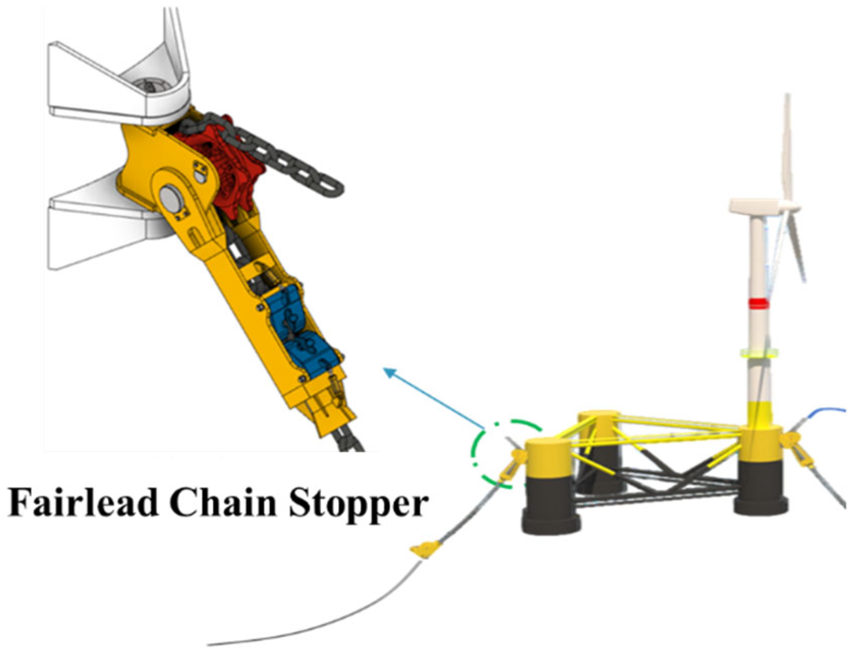
The FCS studied in this study is a detachable mooring mechanism designed to streamline the offshore transport and mooring installation of floating offshore wind power systems. This device is designed to facilitate rapid connection and disconnection between the floating platform and mooring lines, offering the functional advantage of rapid platform transport, particularly during emergency sheltering or large-scale maintenance operations under extreme weather conditions such as typhoons. The actual platform mounting of the device is schematically illustrated in Figure 1, and its detailed mechanical configuration is illustrated in Figure 2. As shown in Figure 1, the system to which the FCS is applied is a large-scale 10 MW floating offshore wind turbine with a semi-submersible platform (SFOWT) substructure supported by three columns. The device is directly connected to the mooring chains exposed above the sea surface, supporting the load. It is designed to maintain sufficient structural integrity even under the harshest design conditions for mooring systems, the minimum breaking load (MBL).
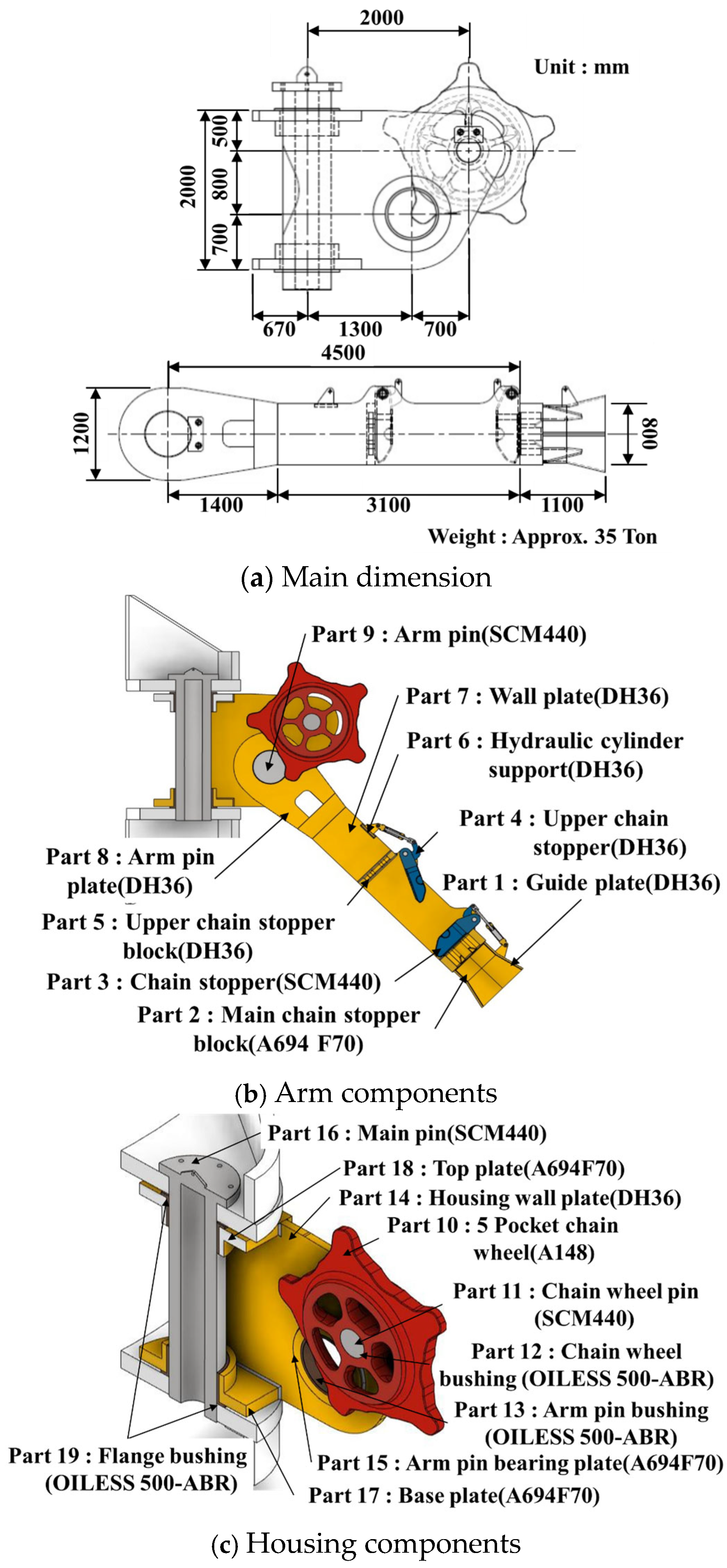
As shown in Figure 2, the FCS is largely composed of two mechanical systems: the Arm system and the Housing system. First, the 5-pocket chain wheel precisely guides the chain’s inflow path during mooring line removal and installation. The Arm section not only functions as a passageway for the chain’s progression, but also acts as a load-dispersing mechanism by evenly distributing the ultimate load transmitted from the Chain Stopper throughout the structure. In particular, the Chain Stopper and Upper Chain Stopper are key support members that directly bear the load generated throughout the mooring line operation, coupling, and disconnection processes. The Housing functions as a support, firmly securing the entire device to the floating platform’s substructure to ensure structural integrity. Furthermore, the hydraulic device controlling the dynamic behavior of the Upper Chain Stopper is supported by a hydraulic cylinder support. All of these key components are designed to utilize pin connections to ensure smooth rotation even under load.
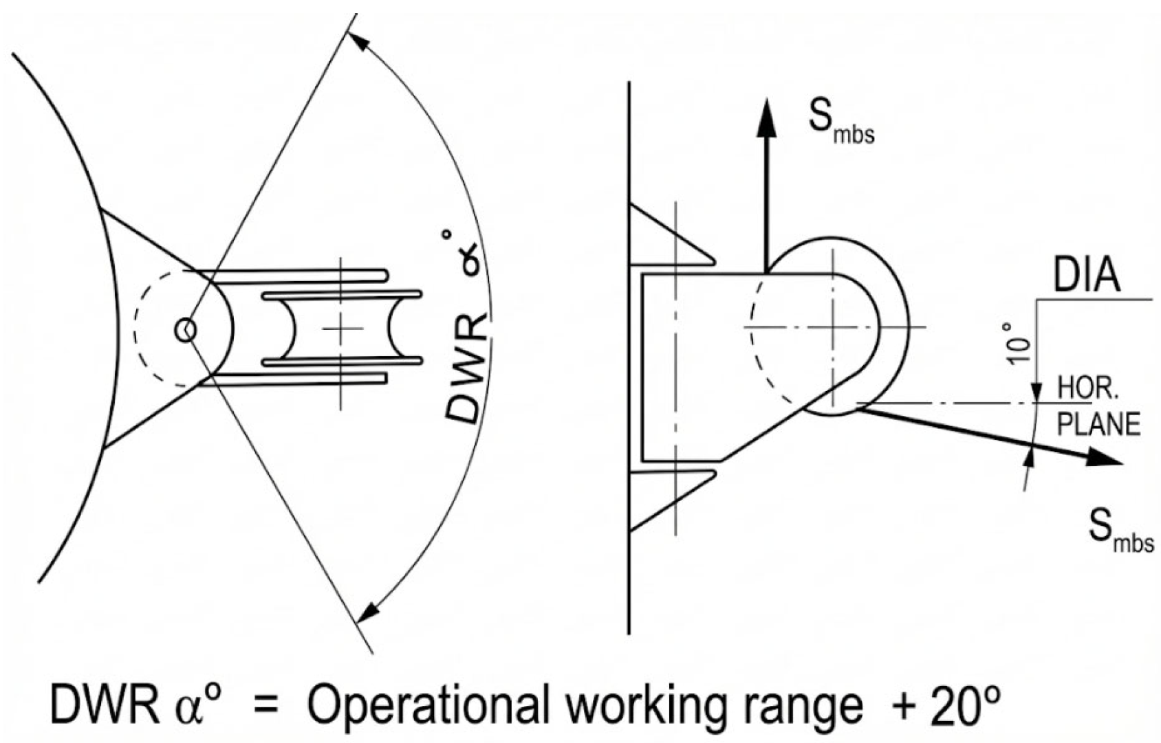
In this study, to strictly verify the structural integrity of the FCS, design load scenarios were established based on international classification codes such as DNV-OS-E301 [14], DNV-ST-0119 [15], and DNV-OS-C101 [16]. Since the removable device is directly mounted on the SFOWT substructure, the design working range (DWR) and design inlet angle (DIA) based on sea level must be determined within the allowable ranges presented in the DNV codes. The specific setting ranges of the DWR and DIA applied to this evaluation model and the kinematic relationships for the load application directions are schematically illustrated in Figure 3. In particular, for the DIA, in addition to the minimum angle of 10° required by the classification society, the condition of 29°, where the maximum mooring tension occurs in the extreme sea state (EWM, ESS) derived through integrated load analysis [17], was examined in parallel to increase structural reliability.
The design load that the chain stopper must withstand during the mooring operation phase was calculated based on the mooring line’s MBL, based on the DNV classification guidelines. For the 147 mm studless chain used in the 10 MW floating offshore wind turbine system studied in this study, the maximum tensile force was set at 21,179 kN, the MBL value. Meanwhile, during towing, when the platform is moved to the installation site, the traction force generated from the hull is transferred to the FCS structure, a detachable device. At this time, the load applied to the upper stopper and chain wheel was calculated to be 3434 kN, reflecting the results of the integrated load analysis.
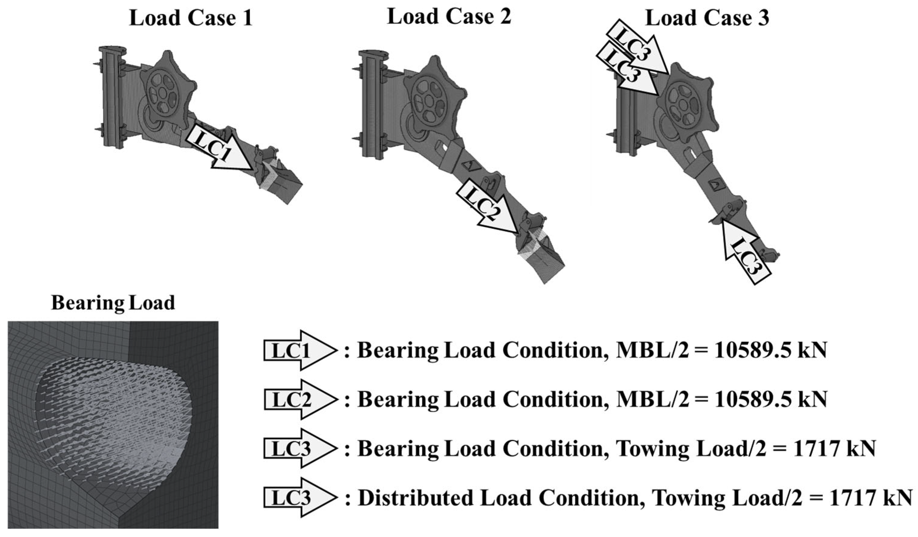
These detailed load conditions are comprehensively summarized in Table 1, and based on this, numerical analysis was performed by dividing them into the LC1 and LC2 scenarios to verify structural safety during mooring and the LC3 scenario to evaluate mechanical soundness during towing.
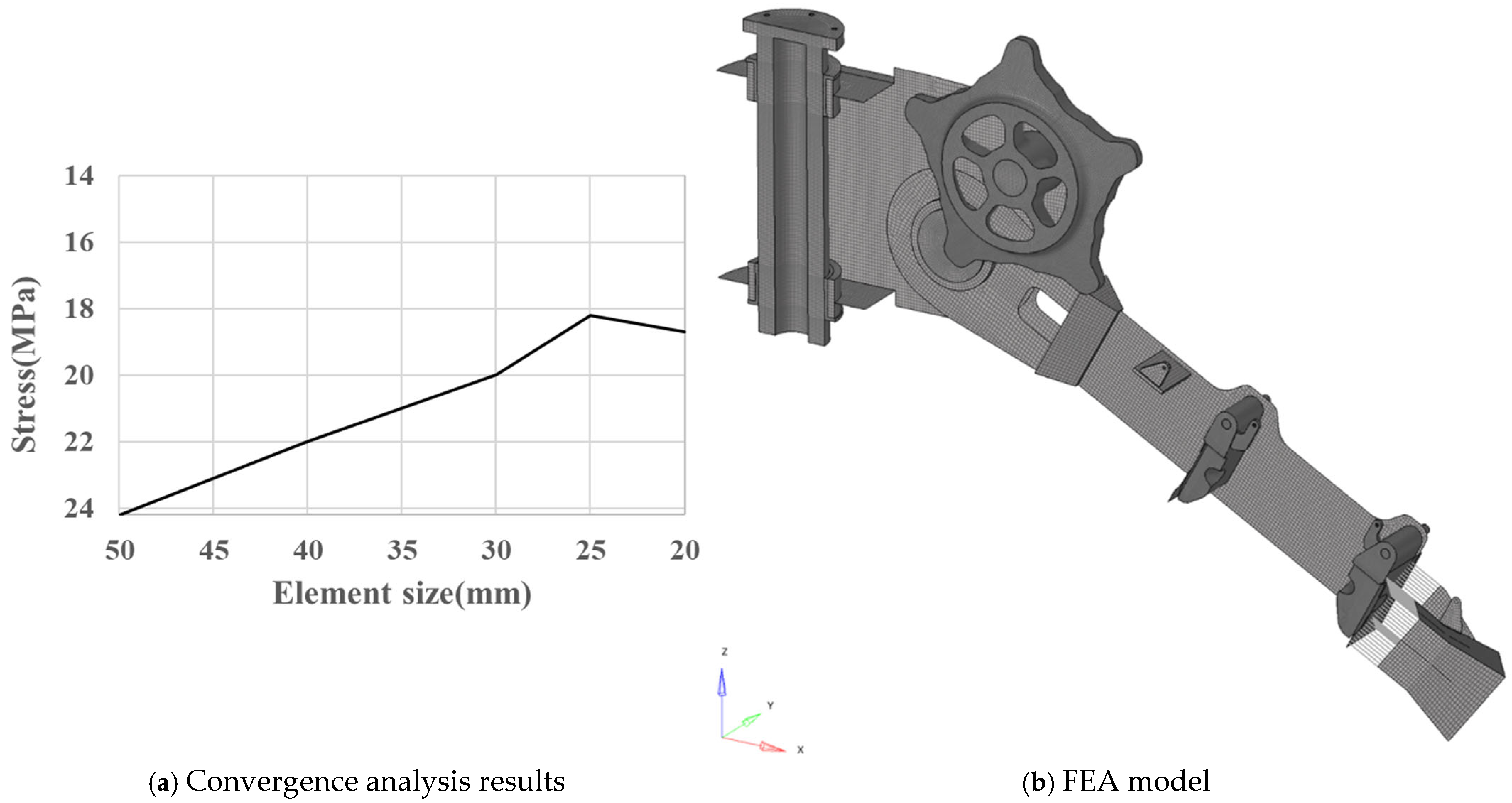
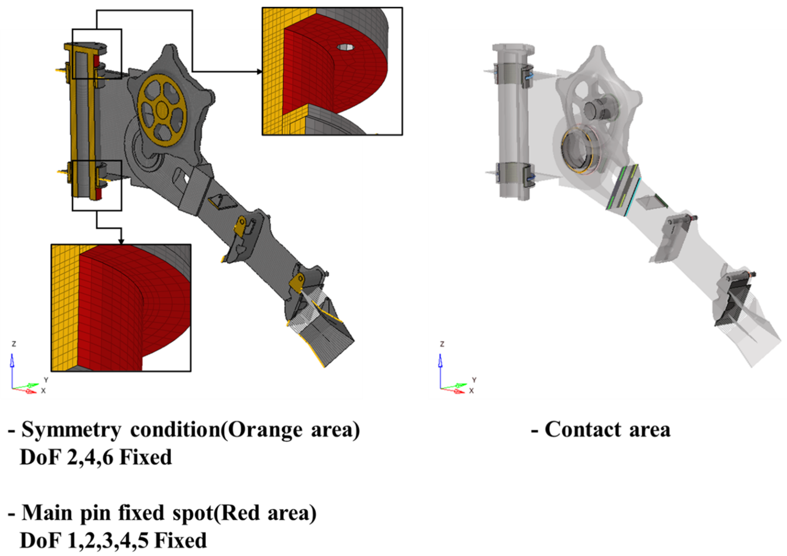
The pre- and post-processing of the finite element modeling and numerical analysis results of this study were performed using Altair’s HyperWorks software—Ver. 2021 [18]. As schematically illustrated in Figure 4, the mesh size was set to 25 mm based on the element size convergence analysis results during mesh generation, and the numerical analysis model constructed through this was precisely composed of a total of 498,879 elements and 384,260 nodes. To simultaneously secure numerical efficiency of the structural analysis and the accuracy of the results, modeling was performed by appropriately mixing shell and solid elements according to the geometric characteristics of the members. In particular, contact conditions were applied to the interfaces where individual components come into contact to precisely reproduce the actual kinematic physics phenomena, thereby enhancing the reliability of the numerical analysis model.
Table 2 details the mechanical properties of each FCS component selected to ensure operational safety in harsh marine environments. The stopper and connecting pin, key support members subject to extreme loads, are made of SCM440, a high-strength alloy steel. The drive bushing and chain wheel, where friction and load simultaneously occur, are made of OILESS500-ABR and A148 steel, respectively, to ensure durability. Furthermore, key structural components, which form the core of the load transfer path, are made of DH36 and A694F70, high-yield steels for ship and marine structures, respectively, to enhance the structural integrity of the detachable device. While these high-performance materials exhibit superior mechanical reliability compared to general structural steels through precise heat treatment, they also come at a relatively high cost. Therefore, weight optimization research is necessary to enhance the economic competitiveness of the system.
The details of the motion degrees of freedom and constraints established in the finite element model are schematically illustrated in Figure 5. The constraints of this model were defined based on the fixed point of the main pin, a key component directly connected to the SFOWT platform. To accurately simulate the device’s actual kinematic behavior, only the rotational degree of freedom along the gravity direction (Z-axis) was permitted, while all other translational and rotational degrees of freedom were constrained. Furthermore, physical contact conditions were applied to implement the interaction between the main pin and the flange bushing, minimizing discontinuities in the load transfer path. In particular, for the boundary region where mixed shell and solid elements are combined due to the geometric complexity of the components, a technique was applied to define the contact surface by replacing the surface of the solid element with a shell element. This approach numerically stabilizes the contact region between the heterogeneous elements, contributing to increased analysis accuracy. Finally, by uniformly applying symmetry boundary conditions to the entire detachable mooring device model, the time and cost required for numerical computation were drastically reduced.
The FCS consists of several parts connected to the arm and housing. Contact conditions were applied to the angle-adjustable pin connection and the contact area between the chain stopper and stopper block. A friction coefficient was applied to the pin connection, and the friction coefficients by application area are summarized in Table 3.
The load conditions established in the numerical analysis model of this study are based on the values calculated in Table 1, and the specific load locations and methods are detailed and visualized in Figure 6. To enhance the accuracy of the structural analysis, the load application method was differentiated according to the operating conditions. First, in the mooring conditions (LC1, LC2), the load was converted to a bearing load form and applied, reflecting the contact characteristics of the curved surface where the mooring chain and chain stopper meet. This method aims to numerically and reliably implement the pressure distribution transmitted to the stopper due to the physical behavior of the chain. Conversely, in the towing condition (LC3), which involves the movement and installation of the platform, the analysis was performed by applying a distributed load to the load-bearing surface area of the upper stopper and chain wheel, which the hull traction force directly affects. This load scenario configuration is a key step in ensuring structural reliability by effectively reproducing the kinematic load transfer mechanism experienced by the FCS, a detachable mooring device, in the harsh marine environment within the finite element model.
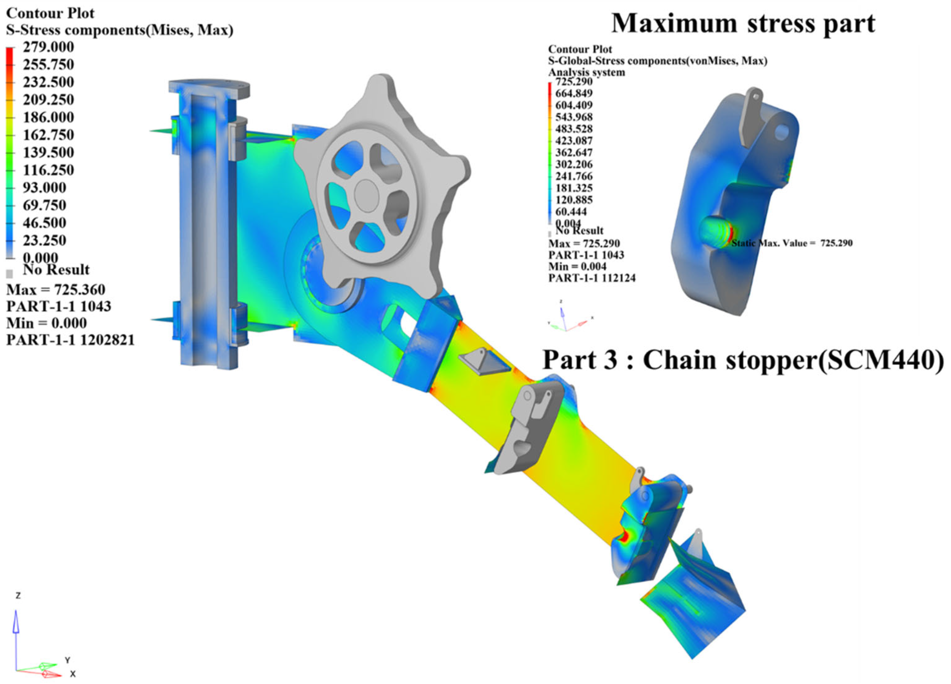
The finite element analysis of the FCS was performed precisely using Abaqus Implicit, a general-purpose numerical analysis software [19]. The von Mises equivalent stress was adopted as a key indicator to examine the structural integrity of the device, and the allowable stress, which serves as the criterion for safety judgment, was defined as 90% of the yield strength for each material according to the guidelines of the international classification code DNV-OS-E301 [14]. The design allowable limits for each material, calculated by applying these strict standards, were set as 436.5 MPa for A694F70, 279 MPa for DH36, 750.6 MPa for SCM440, 526.5 MPa for A148, and 555.3 MPa for OILESS500-ABR, respectively, and were used as a criterion for evaluation. The analysis results for each load scenario, as specified in Table 4, show that the maximum stress values generated under all design load conditions were stably distributed and below the allowable stress limits of the corresponding component materials. These evaluation results demonstrate that this detachable mooring device maintains sufficient structural integrity even under harsh marine operating conditions. In particular, the highest stress levels were observed in the LC2 scenario, where the maximum mooring tension was applied across all analysis conditions. This was primarily observed in the main support members, which were made of high-strength steel, SCM440.
The overall stress behavior of the FCS under the LC2 condition, where maximum mooring tension is applied, is visualized and detailed in Figure 7. A detailed analysis of the numerical analysis results revealed a prominent stress concentration near the chain stopper, a key member primarily supporting the external mooring load. Furthermore, a relatively high level of stress was observed densely distributed around the arm pin bearing plate and arm wall plate, key supports along the primary load transfer path within the structure, compared to adjacent areas. This stress distribution trend suggests that these members play a key role in load transfer and distribution, maintaining the structural integrity of the mooring system.

3. Structural Design Optimization for Weight Minimization

Design optimization problems for complex marine structures, such as mooring systems for floating offshore wind turbines, present limitations in applying traditional mathematical optimization techniques due to the nonlinearity and discontinuity of design variables. Therefore, the field of marine engineering has recently been actively attempting to solve complex design problems by introducing metaheuristic-based global optimization techniques. Previous studies have demonstrated that Benítez-Suárez et al. [20] applied the Phase-Solved Optimization (PSO) algorithm to perform design optimization to determine the optimal member layout and specifications of a jacket structure for a wind turbine. Lai et al. [21] applied the NSGA-II approach to derive a multi-objective optimized shape for a semi-submersible floating platform, considering tradeoffs among cost, stability, and strength. Furthermore, Liu et al. [22] proposed a computational performance improvement method that introduced a hybrid algorithm based on an evolutionary algorithm to enhance the computational efficiency of jacket structure optimization. These research cases suggest that global optimization algorithms can avoid local optima and efficiently explore the design space in marine structure design problems.
In particular, the structural optimization problem of the FCS, the subject of this study, uses steel thickness as a design variable, which is defined as a discrete design variable with only discontinuous values reflecting actual manufacturing processes and specifications. This discrete search space cannot utilize gradient information and exhibits step-like, discontinuous response characteristics, making it difficult to derive a global optimum using gradient-based deterministic search methods. Therefore, the application of an algorithm capable of effectively finding a global optimum within a discrete space through probabilistic search is essential.
In this study, we selected and applied three global optimization techniques: Particle Swarm Optimization (PSO), Nondominated Sorting Genetic Algorithm II (NSGA-II), and Evolutionary Algorithm (EA) to minimize the weight of FCSs. These techniques share the advantage of simultaneously operating multiple populations to explore the design space, reducing the risk of localized solutions and providing superior global search capabilities. Specifically, PSO demonstrates rapid convergence even in discrete variable problems through information sharing between particles, while NSGA-II utilizes elite preservation strategies and congestion distance calculations to secure solution diversity. Furthermore, EA, based on natural selection and genetic principles, demonstrates flexible search performance in nonlinear structural optimization problems with constraints. This study aims to compare and apply these three algorithms to derive the optimal optimization methodology for the FCS structural design problem.

3.1. Theoretical Background

The Particle Swarm Optimization (PSO) algorithm is a metaheuristic optimization technique that models the social behavior of swarming organisms, such as flocks of birds or schools of fish that migrate in search of food. This algorithm simulates the process in which particles move as if flying within a design space, maintaining their own speed and directionality. Each particle possesses kinematic characteristics that determine its next movement point in real-time by referencing both its own individual optimal position and the global optimal position reached by the entire swarm. Since PSO considers multiple candidate solutions simultaneously from the early stage of the search and repeatedly updates the velocity and position, it exhibits highly efficient performance in searching for the global optimum and discrete optimum [23]. When the algorithm is activated, the initial coordinates and velocity vectors of particles are randomly generated within the design range, such as the thickness dimension set as an optimization variable. At each iteration (k + 1), the velocity vector of each particle is precisely updated based on the position and velocity information from the previous step (k) and the evaluation value of the objective function, as shown below, and converges to the optimal point.
v k + 1 i = ω v k i + c 1 r 1 ( p k i x k i ) + c 2 r 2 ( p k g x k i )
Specifically, the main parameters applied in Equation (1) are as follows: r 1 and r 2 are randomly generated numbers between 0 and 1, and ω, c 1 , and c 2 represent the Inertia factor, Self-confidence factor, and Swarm-confidence factor, which control the convergence speed and direction of the system, respectively. Here, p k i represents the individual optimal position that the i th particle has reached so far, forming the Cognitive contribution of the algorithm, and p k g represents the best global optimal position among the points explored by the entire swarm up to step k, forming the Social contribution. Based on Equation (1), the velocity vector of the i th particle at step k + 1 is precisely updated by combining the velocity information of the previous step, the particle’s own past experience, and the best information of the entire swarm. Based on the new velocity vector thus derived, the position of the i th particle moves to a new coordinate within the design space, as shown in Equation (2).
x k + 1 i = x k i + v k + 1 i · t
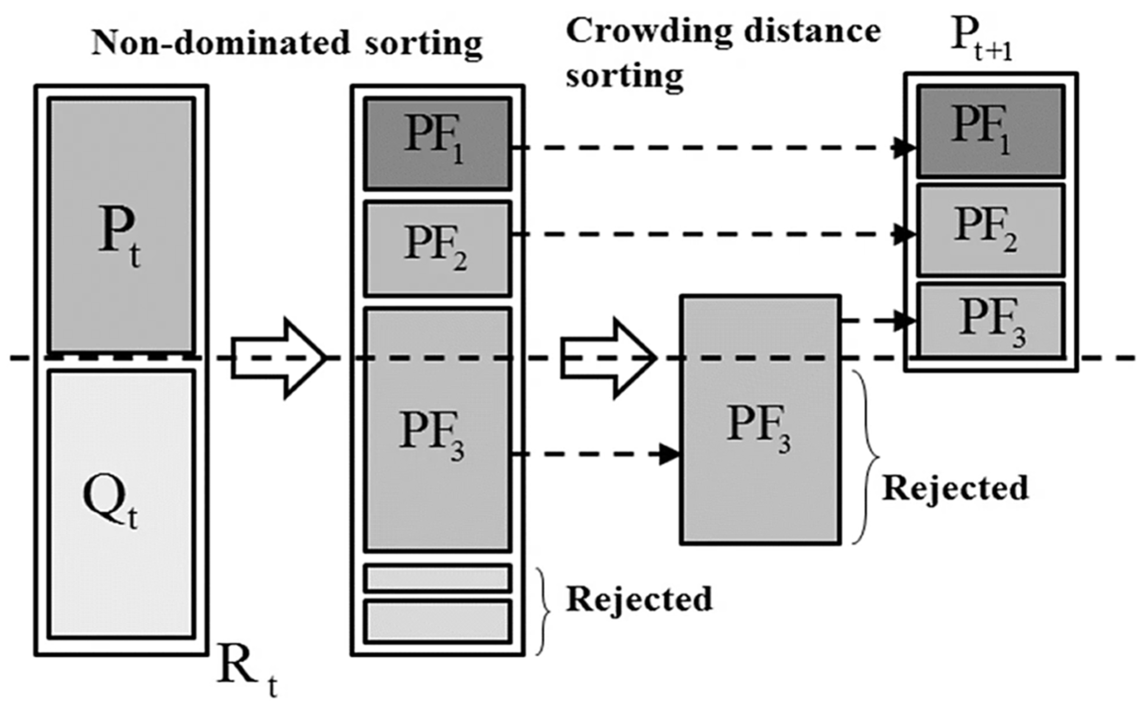
The Nondominated Sorting Genetic Algorithm-II (NSGA-II) is a fast, elite-conserving, multi-objective genetic algorithm (MOEA) [24]. This algorithm simulates the evolutionary process of organisms to simultaneously optimize multiple conflicting objective functions, and is highly efficient in finding the entire Pareto-optimal solution set in a single run. NSGA-II reduces the high computational complexity of existing algorithms to O ( M N ) 2 and innovatively resolves the absence of elitism and the difficulty of setting sharing parameters. When the algorithm is run, an initial parent population P O is randomly generated within the design range, and a rank is assigned to each individual according to the optimal level through non-dominated sorting. Thereafter, at each iteration step (t), an offspring population Q t is generated through selection, crossover, and mutation operators, and the next-generation individuals are precisely selected within the entire population that integrates parents and offspring based on the crowded-comparison operator below.
i < j n       i f       i r a n k < j r a n k o r   ( i r a n k = j r a n k a n d   i d i s t a n c e > j d i s t a n c e )
Looking specifically at the key properties applied in Equation (3), ‘rank’ and ‘distance’ are indicators that control the optimal performance of each individual and the diversity of solutions. ‘Rank’ is the non-dominated rank, and the lower the value, the better the solution that is closer to the Pareto front. This determines the convergence of the algorithm. ‘Distance’ is the crowding distance that indicates the density around the individual within the same rank. The larger the value, the more sparse the solution is located in the surrounding area with fewer other solutions, thereby securing the spread of the solution set. Based on Equation (3), when comparing two individuals, the individual with the lower rank is given priority, but if the ranks are the same, the individual with the further crowding distance (in the less dense area) is selected, thereby updating the population. The next-generation parent population P t + 1 produced in this way becomes the basis for generating new offspring, as in Equation (4).
Q t + 1 = m a k e   n e w   p o p ( P t + 1 )
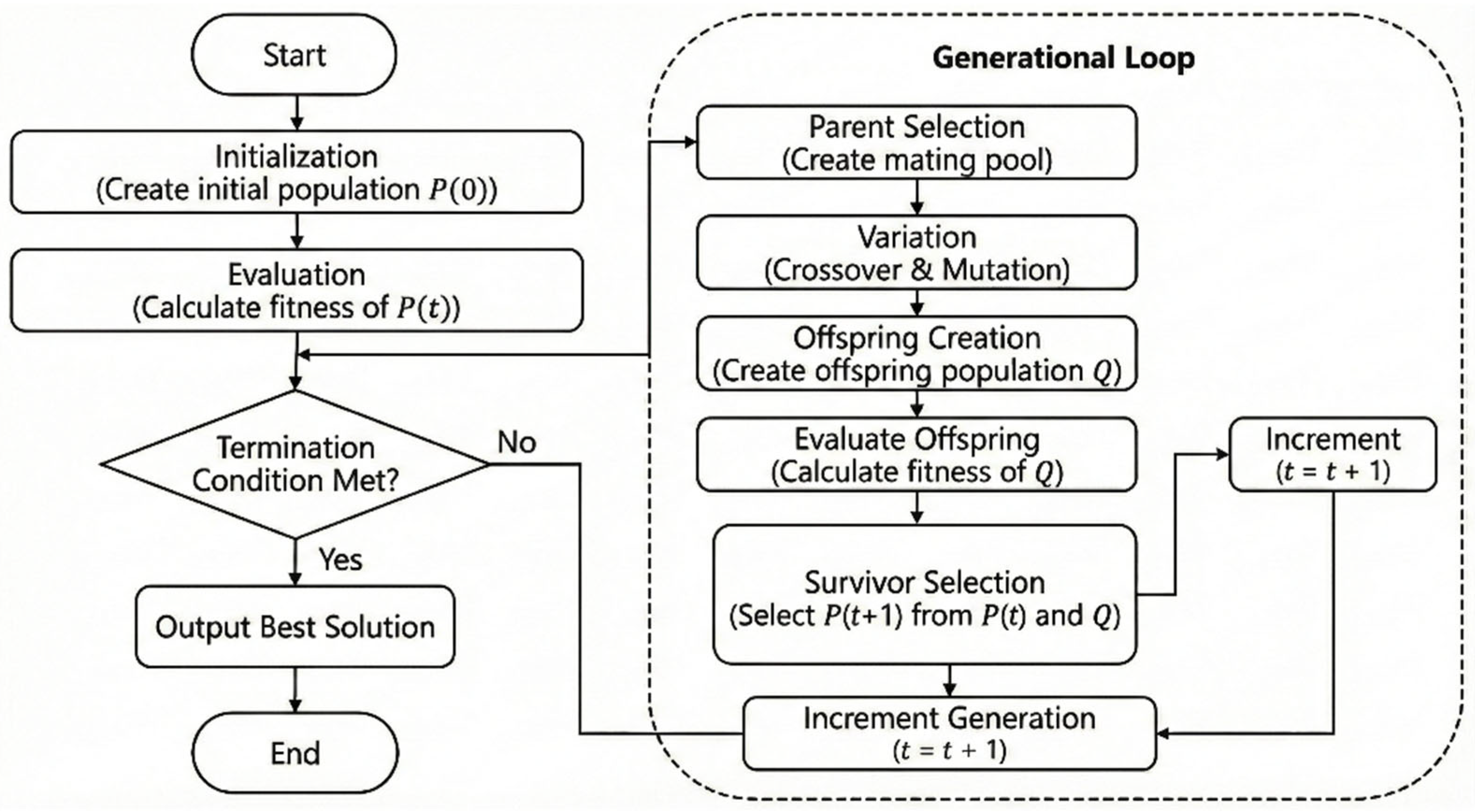
Through this process, NSGA-II simultaneously achieves the dual goals of rapid convergence to the Pareto front and uniform distribution of solutions, demonstrating outstanding optimization performance even in complex engineering problems with constraints. The NSGA-II process is illustrated in Figure 8.
Evolutionary Algorithms (EAs) are probabilistic optimization techniques based on natural selection and genetic law [25]. Unlike traditional gradient-based methods, which start from a single solution, EAs simultaneously operate on a population of multiple solutions, distributing candidate solutions across the entire search space and reducing the risk of being trapped in a local optimum. Because of these population-based search characteristics, EAs are widely applied to real-world engineering problems where design variables exhibit nonlinearity, discontinuity, and multiple local solutions as a global search procedure that does not require differential information.
EA repeatedly applies key operators such as selection, crossover, and mutation from an initialized population every generation (t) to create the next-generation population P t + 1 . The selection operator ensures that solutions with relatively superior fitness are chosen as parents more frequently, thereby transmitting the beneficial information discovered so far to the next generation. Crossover and mutation then reorganize and perturb the information in the parent solutions, exploring new areas and maintaining a balance between exploration and exploitation.
In particular, in real parameter GAs that handle continuous design variables, the Simulated Binary Crossover (SBX) and Polynomial Mutation operators are mainly used. Both operators use a distribution index as a parameter to control the search radius, determining whether offspring solutions are generated near the parent solution or spread out over a wider range. A small distribution index favors a wide search, which is advantageous for global search in the early stages. A larger value enhances detailed search near the parent solution, which is effective for fine-tuning during the convergence stage.
When constraints exist, the Constraint Violation (CV) of each solution is calculated as the sum of the normalized violations, as in Equation (5).
C V x = j = 1 J g ¯ j ( x ) + k = 1 K h ¯ k ( x )
Here, α means α if α < 0 and 0 otherwise, and g j ( x ) and h k ( x ) represent inequality and equality constraints, respectively. The CV value defined in this way quantitatively indicates how much a solution violates the constraints and is used for comparison according to the principle of constraint domination. That is, when comparing two different solutions, the feasible solution with a CV of 0 is preferentially selected, and if both solutions violate the constraints, the solution with the smaller CV value is considered the superior solution. As a result, even if the objective function value is somewhat unfavorable, the solution that better satisfies the constraints always takes priority, and the search process is naturally guided to the permissive solution region. The progress of the EA described above is shown in Figure 9.
PSO, NSGA-II, and EA, which were compared and analyzed in this study, are metaheuristic algorithms that are widely used not only for simple structural optimization but also for parameter tuning of control systems and the search of adaptive event-triggered design spaces. Since these algorithms adopt a probabilistic search method that does not require differential information, they can provide high flexibility and methodological consistency in iterative design environments where the objective function is nonlinear and discontinuous, such as ‘control-structure integrated optimization’ or ‘adaptive design scenarios’.
Furthermore, since each optimization technique has a different mathematical search mechanism, it is expected to exhibit different convergence directions in discrete design variable problems like the one in this study. Specifically, PSO, based on continuous vector operations; NSGA-II, which emphasizes the diversity of multiple objective solutions; and EA, which is advantageous for searching discontinuous spaces through stochastic genetic operations, are expected to differ in terms of convergence speed and efficiency during the weight minimization process, which is a single objective function. Therefore, this study aimed to select the most suitable and practical methodology for optimal FCS design reflecting actual manufacturing environments by comparing and analyzing the mathematical characteristics of these algorithms.

3.2. Optimization Results and Discussion

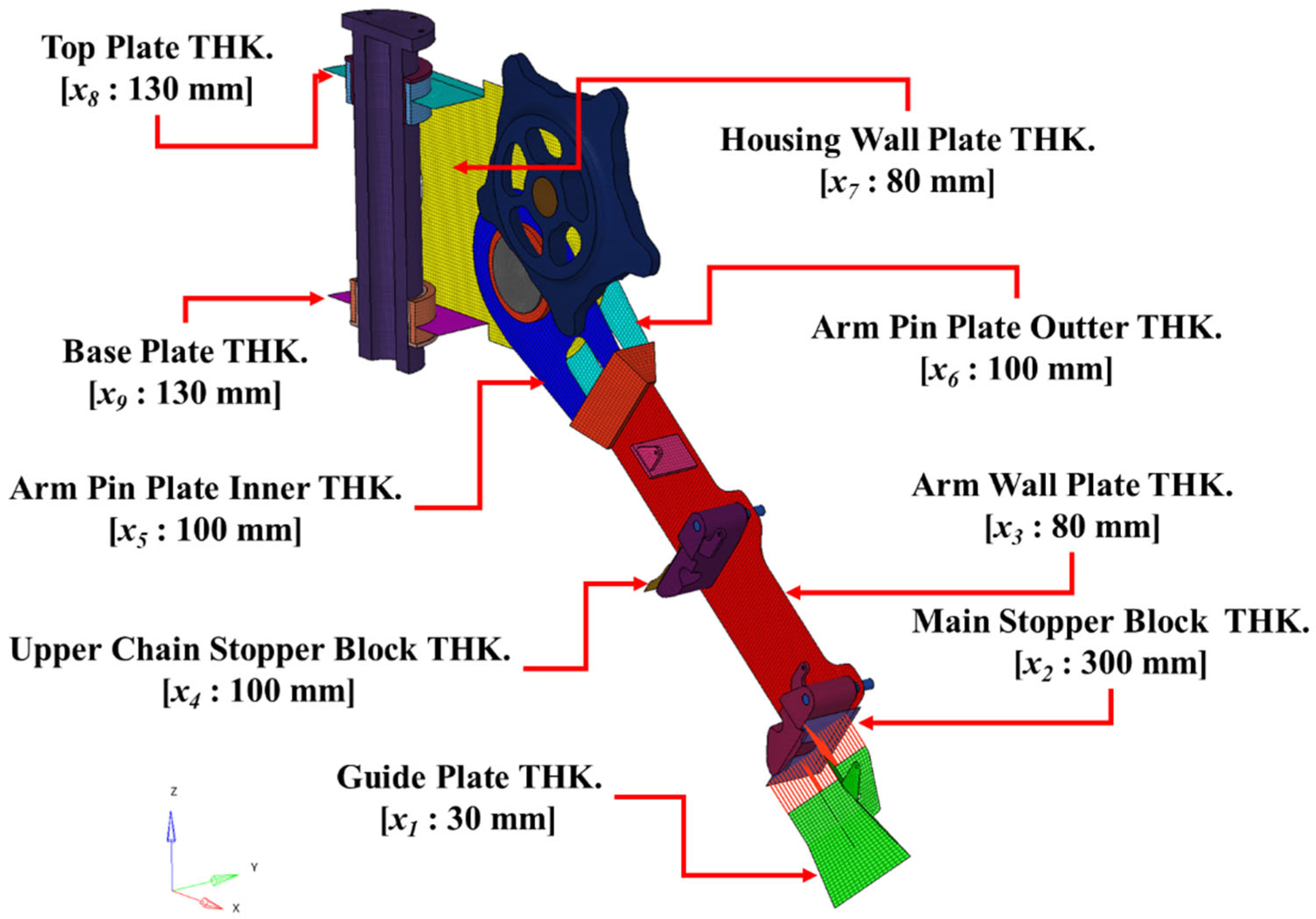
The design factors and initial design thickness for optimal design of FCS are visualized in Figure 10.
The formalization of optimization for FCS structural design is defined as in Equation (6).
                  M i n i m i z e   W = W x 1 , x 2 , x 3 , x 4 , x 5 , x 6 , x 7 , x 8 , x 9   s . t .     g 1 x 1 , x 2 , x 3 , x 4 , x 5 , x 6 , x 7 , x 8 , x 9 = L C 1   D H 36   S t r e s s 279   MPa                   g 2 x 1 , x 2 , x 3 , x 4 , x 5 , x 6 , x 7 , x 8 , x 9 = L C 1   A 694 F 70   S t r e s s 436.5   MPa                   g 3 x 1 , x 2 , x 3 , x 4 , x 5 , x 6 , x 7 , x 8 , x 9 = L C 2   D H 36   S t r e s s 279   MPa                   g 4 x 1 , x 2 , x 3 , x 4 , x 5 , x 6 , x 7 , x 8 , x 9 = L C 2   A 694 F 70   S t r e s s 436.5   MPa                   g 5 x 1 , x 2 , x 3 , x 4 , x 5 , x 6 , x 7 , x 8 , x 9 = L C 3   D H 36   S t r e s s 279   MPa                   g 6 x 1 , x 2 , x 3 , x 4 , x 5 , x 6 , x 7 , x 8 , x 9 = L C 3   A 694 F 70   S t r e s s 436.5   MPa                             24 x 1 36   mm                             240 x 2 360   [ mm ]                             64 x 3 96   [ mm ]                             80 x 4 120   [ mm ]                             80 x 5 120   [ mm ]                             80 x 6 120   [ mm ]                             64 x 7 96   [ mm ]                             104 x 8 156   [ mm ]
In Equation (6), the upper limits of the constraints for each LC were set to 279 MPa and 436.5 MPa, which are the allowable stresses of the main design factor materials DH36 and A694F70, respectively, in accordance with the condition that the allowable stress is 90% of the material yield stress in accordance with DNV-OS-E301 [14]. The approach of using the safety margin for the allowable stress or material yield strength specified by the classification society as a structural strength constraint has been adopted in several studies [26,27,28].
The parameters applied for each optimization are shown in Table 5, Table 6 and Table 7.
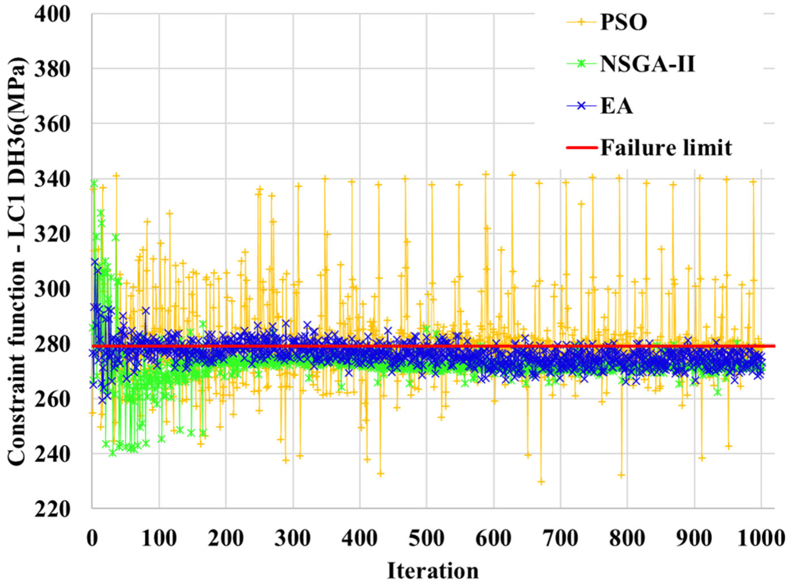
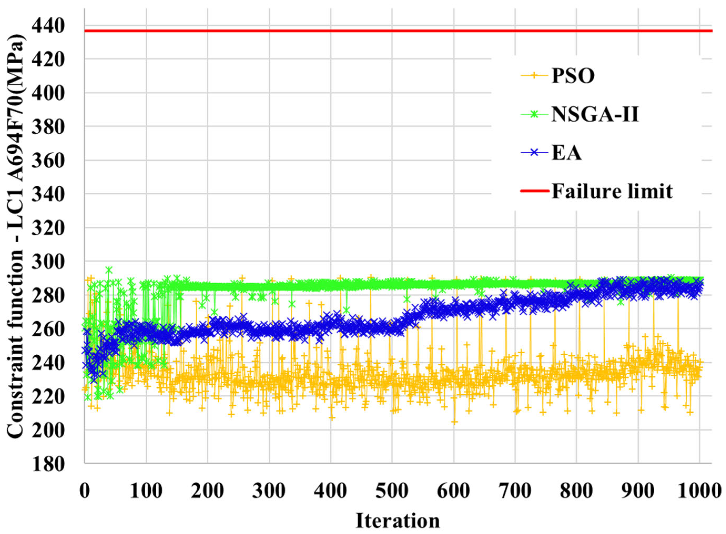
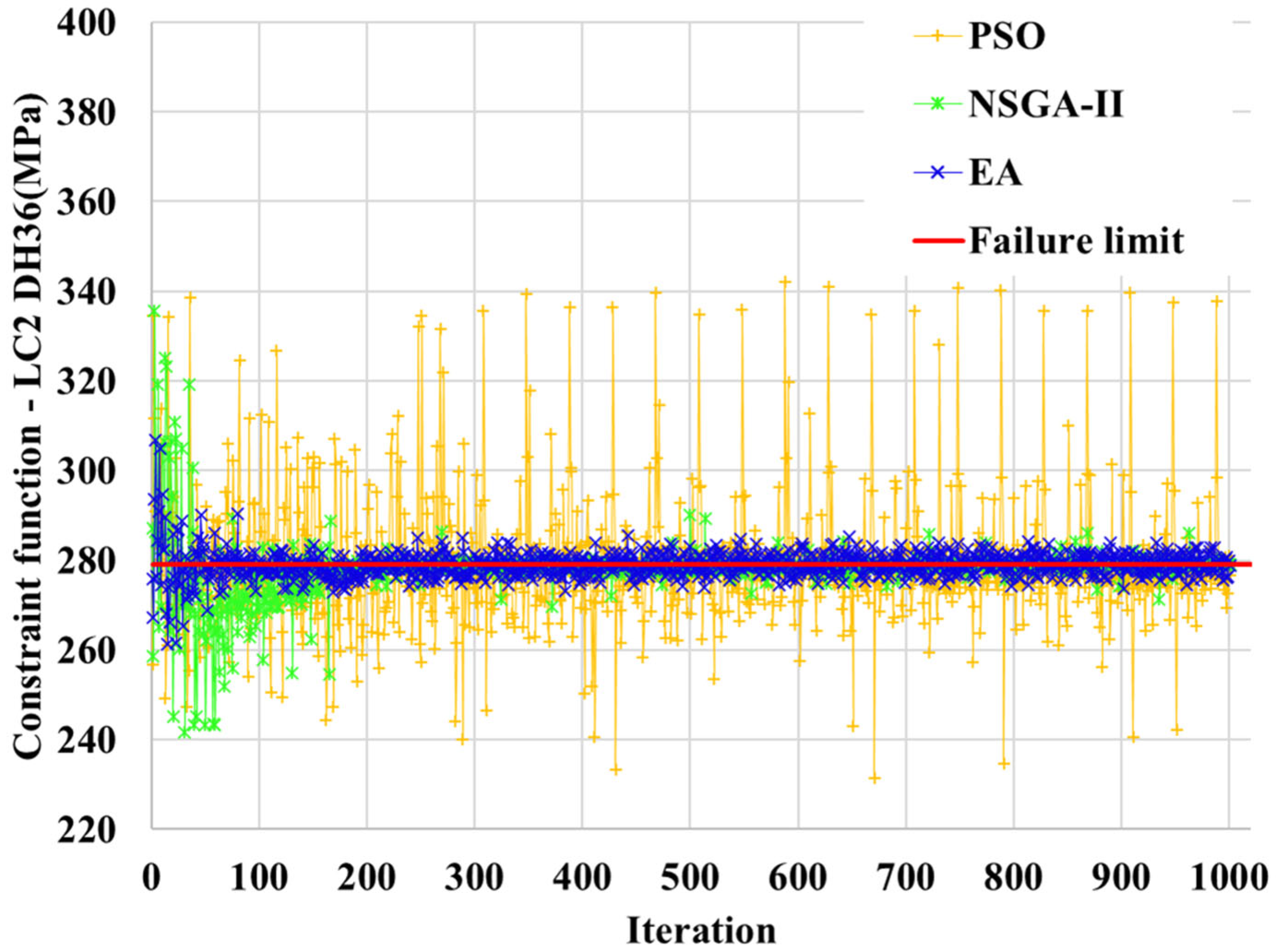
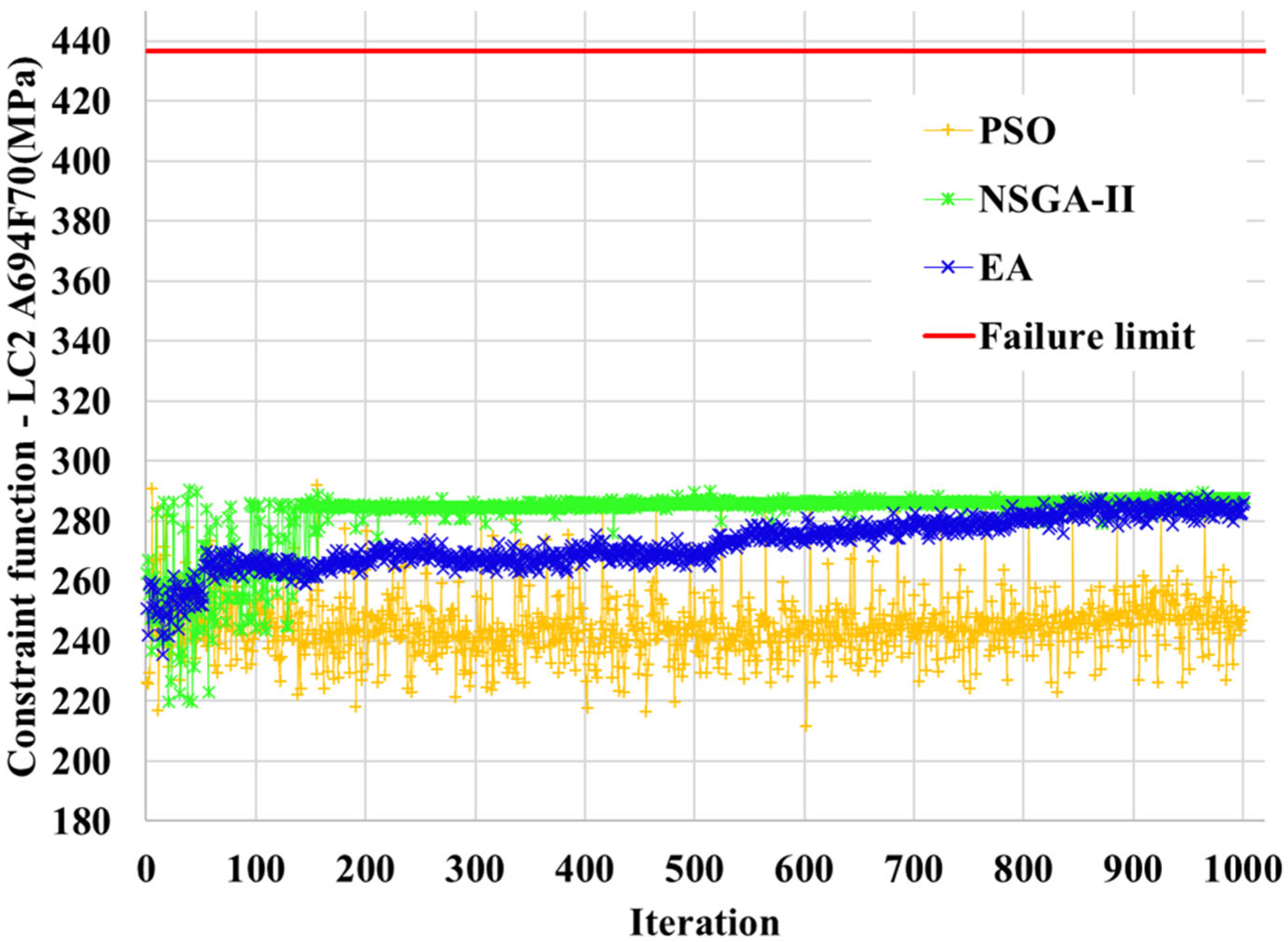
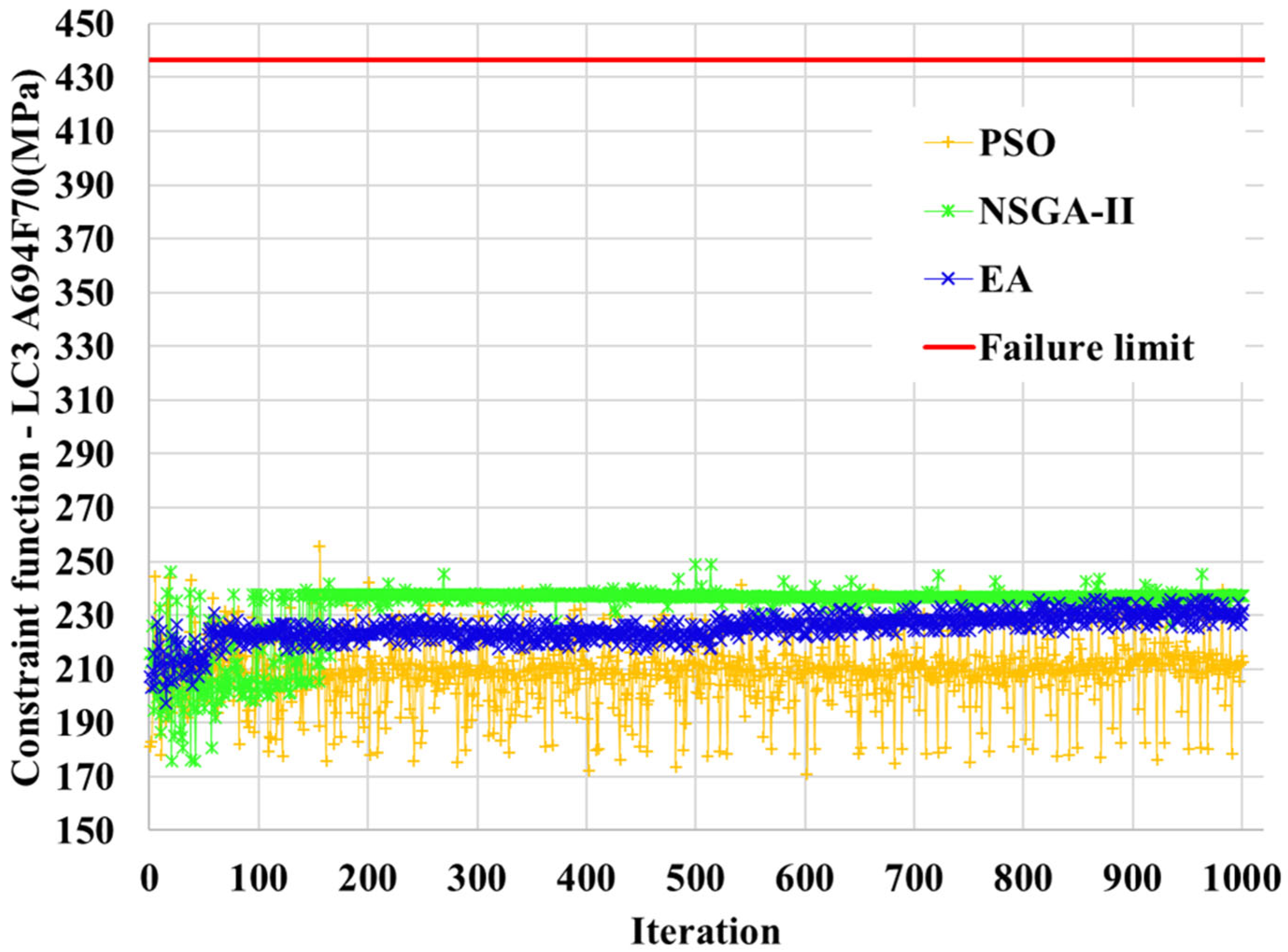
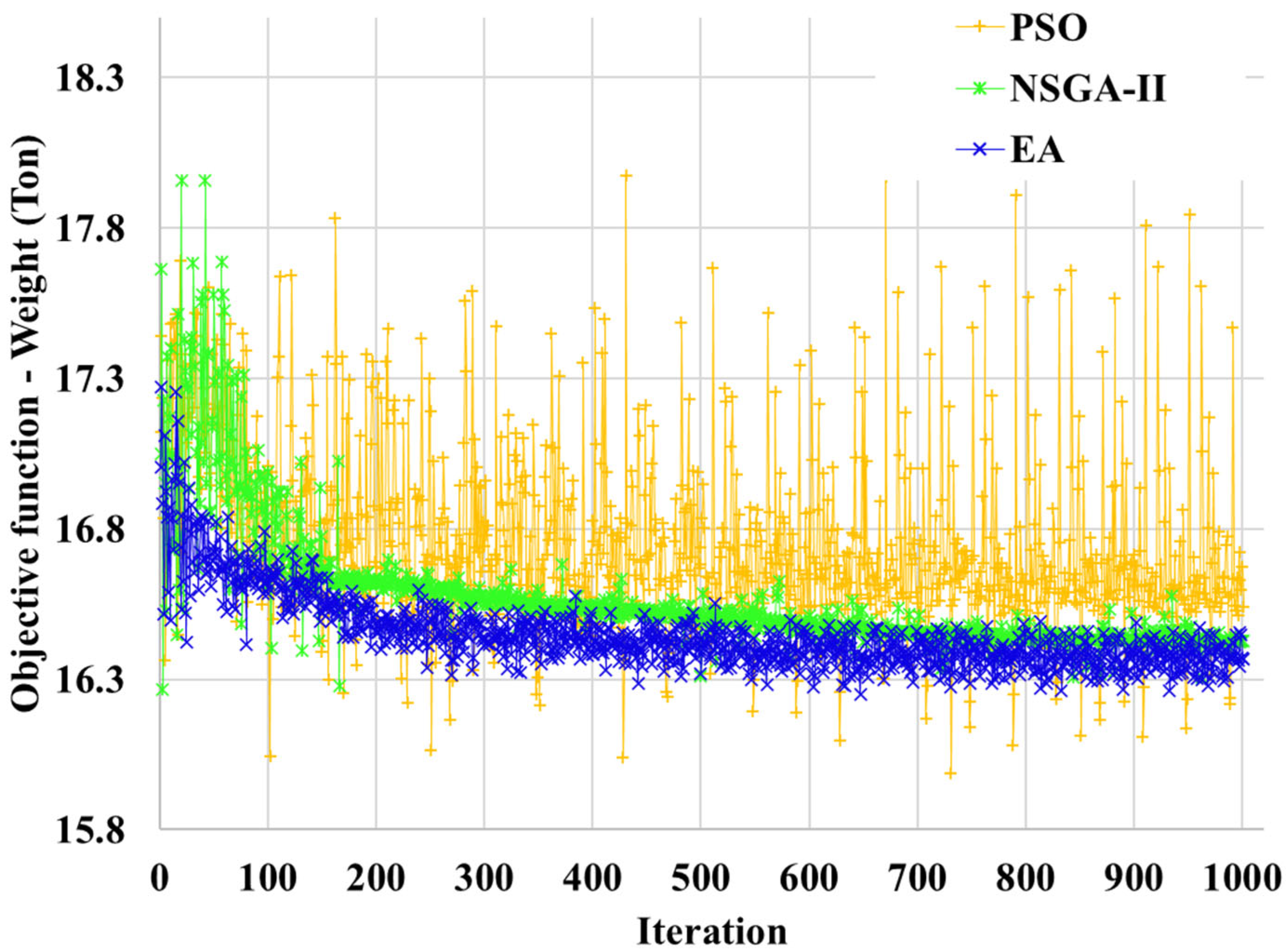
The results of FCS optimization using each optimization theory are summarized in Table 8, Table 9 and Table 10, including optimal design variables, constraint response values, and objective functions. When applying discrete and continuous design variables for each optimization theory, the difference in weight reduction rate of the objective function by design variable type was confirmed to be up to 0.73% when PSO was applied. When continuous design variables were applied, the DH36 response function of the optimal design point was found to be closer to the constraints, and the weight (the objective function) was reduced slightly, but the effect was minimal. When comparing the three optimization results applying PSO, NSGA-II, and EA, EA showed the highest weight reduction rate of 3.73%. Furthermore, EA showed better objective function achievement when using discrete design variables than when using continuous design variables. These results demonstrate that optimal design utilizing discrete design variables and EA is the most effective for FCS optimization. EA’s superior performance was interpreted as a result of the problem’s search space and constraint characteristics being better aligned with EA’s select-crossover-mutation operational structure. While PSO is prone to premature convergence in design spaces where clusters rapidly aggregate into specific regions and multiple local optima exist, EA simultaneously performs global search and local refinement through generational crossover and mutation, thereby maintaining a more balanced diversity and convergence performance in the solution population. Furthermore, NSGA-II is a multi-objective algorithm that focuses on securing the distribution and diversity of the Pareto front. Therefore, in situations like this one where maximizing a single objective function is practically crucial, it is difficult to apply as strong a convergence pressure as EA. Therefore, EA effectively evolves engineeringly feasible solutions through problem-specific constraint handling and fitness definition, and is believed to produce optimal design solutions with higher performance than PSO and NSGA-II. The convergence of the response function constraints of LC2 DH36 using the optimal design methods using discrete design variables is shown graphically in Figure 11, Figure 12, Figure 13, Figure 14, Figure 15 and Figure 16, and the convergence of the objective function is shown graphically in Figure 17.
As a result of analyzing the constraint convergence tendency of the response value for each optimization technique by applying discrete design variables, the allowable stress of DH36 in each LC all converged to around 279 MPa, and among them, the response value of LC2 was found to be closest to the constraint condition. On the other hand, in none of the cases did the allowable stress constraint of 436.5 MPa of A694F70 in each LC come close, and generally tended to converge at around 240 to 290 MPa. It is believed that this is mainly due to the fact that the thickness of the design variable to which the A694F70 material was applied was not sufficiently reduced in order to preferentially satisfy the allowable stress of DH36 within the constraint condition. In particular, in the case of the PSO technique, the constraint proximity of the A694F70 response value in LC1 and LC2 was found to be the lowest compared to the other two optimization techniques.
After comprehensively reviewing the convergence graph, it was determined that the most dominant response value in the optimal design of the FCS was DH36, and it was confirmed that the response value for A694F70 did not show relatively large changes throughout the optimization process.

4. Conclusions

This study conducted an optimal design study for the FCS (floating control system), a key component supporting the operational efficiency and safety of large-scale floating offshore wind power systems (10 MW or greater). This study aimed to minimize weight while maintaining structural safety. The main conclusions derived from the analysis are as follows.
First, the strength evaluation was performed by establishing design load scenarios for mooring and towing conditions in accordance with the DNV guidelines, an international classification code. As a result, it was confirmed that the initial design stably satisfies the allowable stress criteria for high-strength steel (DH36, A694F70, etc.) in all analysis conditions (LC1, LC2, LC3) and secures sufficient structural safety.
Second, the weight difference between the discrete design variables reflecting actual manufacturing specifications and the theoretical continuous variable optimization results was found to be very minimal, at a maximum of 0.73%. This suggests that in the actual marine equipment manufacturing environment, where standard steel plate specifications must be adhered to, discrete optimization is a reasonable approach that can ensure the immediate field applicability of the design while maintaining theoretical optimal performance.
Third, EA achieved the highest weight reduction rate of 3.73% in problems involving complex constraints and discontinuous design spaces. This result quantitatively confirms that EA, which uses stochastic genetic operators, is mathematically superior in terms of the convergence speed and efficiency of a single objective function compared to PSO, which performs inter-particle vector operations, or NSGA-II, which emphasizes the diversity of multiple objective solutions.
Fourth, the optimization framework proposed in this study is not limited to a specific piece of equipment, such as FCS. The discrete optimization process combining high-fidelity FEA and metaheuristic algorithms can be universally extended and applied to weight reduction designs for various large offshore steel structures such as winches, fairleads, and platform brackets that utilize standard steel plates.
In conclusion, this study performed optimal design by assuming static and deterministic load conditions based on international classification society regulations and fixed allowable stress constraints. However, considering the high variability and dynamic characteristics of actual marine environments, it is expected that the robustness of the system can be further enhanced by expanding the approach to adaptive load mitigation or real-time optimal design that incorporates dynamic characteristics. In particular, this methodology is considered to play a crucial role as core foundational data for robust design incorporating adaptive constraint handling, which adjusts safety margins in real-time according to operating conditions, as well as for lifecycle-oriented structural tuning technology that maximizes maintenance efficiency by feeding back real-time structural status monitoring data.

Author Contributions

Conceptualization, C.-Y.S.; methodology, C.-Y.S.; software, M.-S.C.; validation, M.-S.C. and C.-Y.S.; formal analysis, M.-S.C.; investigation, M.-S.C.; resources, C.-Y.S.; data curation, C.-Y.S.; writing—original draft preparation, M.-S.C.; writing—review and editing, C.-Y.S.; visualization, M.-S.C.; supervision, C.-Y.S.; project administration, C.-Y.S.; funding acquisition, C.-Y.S. All authors have read and agreed to the published version of the manuscript.

Funding

This work was supported by the Korea Institute of Energy Technology Evaluation and Planning (KETEP) and the Ministry of Trade, Industry and Energy (MOTIE) of the Republic of Korea (No. 20213000000030), and the Korea Institute of Marine Science and Technology Promotion (KIMST), and the Ministry of Oceans and Fisheries, Korea (No. 1525013494/PMS5390, Development of basic technologies to evaluate electric-powered system for in eco-friendly ship and demonstrate ship—applicability of carbon-free fuel).

Institutional Review Board Statement

Not applicable.

Informed Consent Statement

Not applicable.

Data Availability Statement

The data presented in this study are available in this article.

Conflicts of Interest

The authors declare no conflicts of interest.

References

  1. Lubovci, R.; Kacar, İ. Design and optimization of an autonomous catamaran for water surface cleaning. Mar. Struct. 2026, 107, 103995. [Google Scholar] [CrossRef]
  2. Gnezdilov, S.G.; Shubin, A.N. Structural optimization of non-rotating floating cranes: Analysis of classical designs and development of a dual-pontoon configuration. Mar. Struct. 2025, 104, 103897. [Google Scholar] [CrossRef]
  3. Kaveh, A.; Hosseini, S.M.; Zaerreza, A. Optimal design of offshore jacket platform using enhanced colliding bodies optimization algorithm. Mar. Struct. 2023, 91, 103441. [Google Scholar]
  4. Monteiro, B.F.; Baioco, J.S.; Albrecht, C.H.; de Lima, B.S.L.P.; Jacob, B.P. Optimization of mooring systems in the context of an integrated design methodology. Mar. Struct. 2021, 75, 102874. [Google Scholar] [CrossRef]
  5. Jung, S.; Jung, J.H.; Koo, B.; Seo, J. Optimization of a mooring system applying a deep neural network under multi-directional environmental conditions. Ocean Eng. 2025, 342, 122992. [Google Scholar] [CrossRef]
  6. Li, Z.; Zhou, K.; Tian, Y.; Zhao, C.; Chang, L.; Zhang, P.; Song, B.; Zheng, S.; Liu, T. Optimization of floating wind turbine mooring system under mooring failure condition based on machine learning. Ocean Eng. 2025, 340, 122334. [Google Scholar] [CrossRef]
  7. Wu, Y.; Chen, H.; Qiu, L.; Huang, X. Optimization of a new pulley–weight mooring system based on neural network and particle swarm optimization. Ocean Eng. 2025, 334, 121589. [Google Scholar] [CrossRef]
  8. Cheong, M.S.; Song, C.Y. Discrete Design Optimization of Detachable Mooring System for Floating Offshore Wind Turbine Based on Global Exploration Algorithm and Surrogate Models. J. Ocean Eng. Technol. 2025, 39, 123–135. [Google Scholar] [CrossRef]
  9. Kang, S.W.; Lee, S.J. Study on Optimization of Design Parameters for Offshore Mooring System using Sampling Method. J. Ocean Eng. Technol. 2018, 32, 223–229. [Google Scholar] [CrossRef]
  10. Ye, X.; Zheng, P.; Qiao, D.; Zhao, X.; Zhou, Y.; Wang, L. Multi-Objective Optimization Design of a Mooring System Based on the Surrogate Model. J. Mar. Sci. Eng. 2024, 12, 1853. [Google Scholar] [CrossRef]
  11. Kostecka, E.; Miller, T.; Durlik, I.; Nerć, A. Artificial Intelligence in Floating Offshore Wind Turbines: A Critical Review of Applications in Design, Monitoring, Control, and Digital Twins. Energies 2025, 18, 5937. [Google Scholar] [CrossRef]
  12. Xie, H.; Wan, L.; Shi, F.; Xin, J.; Zhou, H.; He, B.; Jin, C.; Michailides, C. A Joint Method on Dynamic States Estimation for Digital Twin of Floating Offshore Wind Turbines. J. Mar. Sci. Eng. 2025, 13, 1981. [Google Scholar] [CrossRef]
  13. Mu, H.; Zhou, T.; Li, B.; Liu, K. Simulation and Experimental Study of Vessel-Borne Active Motion Compensated Gangway for Offshore Wind Operation and Maintenance. J. Mar. Sci. Eng. 2026, 14, 187. [Google Scholar] [CrossRef]
  14. DNV-OS-E301; Position Mooring. Det Norske Veritas: Bærum, Norway, 2021.
  15. DNV-ST-0119; Floating Wind Turbine Structures. Det Norske Veritas: Bærum, Norway, 2021.
  16. DNV-OS-C101; Structural Design of Offshore Units. Det Norske Veritas: Bærum, Norway, 2024.
  17. Institute for Advanced Engineering. Integrated Load Analysis Report; DMS-IA-GEN-DOC-REP-0005; Institute for Advanced Engineering: Yongin, Republic of Korea, 2023. [Google Scholar]
  18. Altair Engineering Inc. HyperWorks User Guide; Altair Engineering: Troy, MI, USA, 2021. [Google Scholar]
  19. Simulia Dassault Systems. Abaqus User Manual; Dassault Systèmes: Richardson, TX, USA, 2020. [Google Scholar]
  20. Benítez-Suárez, B.; Quevedo-Reina, R.; Álamo, G.M.; Padrón, L.A. PSO-based design and optimization of jacket substructures for offshore wind turbines. Mar. Struct. 2025, 101, 103759. [Google Scholar] [CrossRef]
  21. Lai, S.; Liu, H.; Gu, Y.; Li, R.; Fang, L.; Lin, Y.; Drabo, S.; Feng, X. Multi-objective optimization of a semi-submersible floating wind Platform: Integrating cost, stability, and strength. Ocean Eng. 2025, 341, 122428. [Google Scholar] [CrossRef]
  22. Liu, D.P.; Lin, T.Y.; Huang, H.H. Improving the Computational Efficiency for Optimization of Offshore Wind Turbine Jacket Substructure by Hybrid Algorithms. J. Mar. Sci. Eng. 2020, 8, 548. [Google Scholar] [CrossRef]
  23. Kennedy, J.; Eberhart, R.C.; Shi, Y. Swarm Intelligence; Morgan Kaufmann: San Francisco, CA, USA, 2001. [Google Scholar]
  24. Deb, K.; Pratap, A.; Agarwal, S.; Meyarivan, T. A fast and elitist multiobjective genetic algorithm: NSGA-II. IEEE Trans. Evol. Comput. 2002, 6, 182–197. [Google Scholar] [CrossRef]
  25. Deb, K. Multi-Objective Optimization Using Evolutionary Algorithms; John Wiley & Sons: Chichester, UK, 2001. [Google Scholar]
  26. Song, C.Y.; Lee, J.; Choung, J. Reliability-based design optimization of an FPSO riser support using moving least squares response surface meta-models. Ocean Eng. 2011, 38, 304–318. [Google Scholar] [CrossRef]
  27. Lee, D.J.; Song, C.Y.; Lee, K. Surrogate model based approximate optimization of passive type deck support frame for offshore plant float-over installation. J. Ocean Eng. Technol. 2021, 35, 131–140. [Google Scholar] [CrossRef]
  28. Song, C.Y. Probabilistic design optimization of shipboard radar mast by adopting RBFN meta-model and various reliability methods. Int. J. Nav. Archit. Ocean Eng. 2025, 17, 100667. [Google Scholar] [CrossRef]
Figure 1. FCS concept.
Energies 19 01893 g001
Figure 2. Overall design configuration of the FCS.
Energies 19 01893 g002
Figure 3. Load application angles [14].
Energies 19 01893 g003
Figure 4. FEA model of the FCS.
Energies 19 01893 g004
Figure 5. Boundary conditions.
Energies 19 01893 g005
Figure 6. Load condition of FEA.
Energies 19 01893 g006
Figure 7. LC2 stress contour results (unit: MPa).
Energies 19 01893 g007
Figure 8. NSGA-II procedure [24].
Energies 19 01893 g008
Figure 9. Evolutionary Algorithm procedure.
Energies 19 01893 g009
Figure 10. Design factor for optimization.
Energies 19 01893 g010
Figure 11. Convergence results of LC1 DH36 constraint.
Energies 19 01893 g011
Figure 12. Convergence results of LC1 A694F70 constraint.
Energies 19 01893 g012
Figure 13. Convergence results of LC2 DH36 constraint.
Energies 19 01893 g013
Figure 14. Convergence results of LC2 A694F70 constraint.
Energies 19 01893 g014
Figure 15. Convergence results of LC3 DH36 constraint.
Energies 19 01893 g015
Figure 16. Convergence results of LC3 A694F70 constraint.
Energies 19 01893 g016
Figure 17. Convergence results of objective function.
Energies 19 01893 g017
Table 1. Design load conditions.
# of Load CaseDWRDIAForceOperation
Condition
LC 110°21,179 kNMooring
LC 229°21,179 kNMooring
LC 346°3434 kNTowing
Table 2. Material property of FCS.
Material NameDensity
[Ton/mm3]
Elastic Modulus
[MPa]
Poisson’s
Ratio
Yield Stress
[MPa]
A694F70 (A694)7.85 × 10−9209,0000.3485
DH36 (DH)7.85 × 10−9209,0000.3310
SCM440 (SCM)7.85 × 10−9209,0000.3834
A1487.85 × 10−9209,0000.3585
OILESS500-ABR (ABR)7.4 × 10−9126,0000.3617
Table 3. Friction coefficient of contact area.
CONTACT AREAContact TypeFriction Coefficient
Main pinFlange bushingSurface-to-surface contact0.3
Flange bushingTop plateSurface-to-surface contact0.3
Flange bushingBase plateSurface-to-surface contact0.3
Arm pinArm pin bushingSurface-to-surface contact0.3
Arm pin bushingArm pin bearing plateSurface-to-surface contact0.3
Chain wheel pinChain wheel bushingSurface-to-surface contact0.3
Chain wheel bushing5 pocket chain wheelSurface-to-surface contact0.3
Other contact areaTie contact-
Table 4. Structure analysis results of FCS.
# of Load CaseMax. Von Mises Stress (MPa)Structure
Safety
A694DH36SCMA148ABR
LC1242.5
(Part 18)
277.6
(Part 7)
724.7
(Part 3)
0.8
(Part 10)
141.1
(Part 15)
OK
LC2240.8
(Part 18)
277.8
(Part 7)
725.4
(Part 3)
1.1
(Part 10)
141.5
(Part 15)
OK
LC3205.3
(Part 18)
269.9
(Part 5)
230.7
(Part 9)
137.8
(Part 10)
70.9
(Part 15)
OK
Table 5. Parameter for PSO.
ParameterValueParameterValue
Maximum iterations100Global increment0.9
Number of particles10Particle increment0.9
Inertia0.85Maximum velocity0.1
Table 6. Parameter for NSGA-II.
ParameterValueParameterValue
Population size20Crossover distribution index10.0
Number of generations50Mutation distribution index20.0
Crossover probability0.9--
Table 7. Parameter for EA.
ParameterValueParameterValue
Maximum evaluations1000Penalty multiplier1000
Minimum discrete step0.02Penalty exponent2
Table 8. Comparison of design optimum (unit: mm).
Design FactorPSONSGA-IIEA
DiscreteContinuousDiscreteContinuousDiscreteContinuous
x13026.9013024.3642626.640
x2302326.916320296.777324314.400
x38383.7668985.5248484.480
x491105.2379595.7699899.200
x58080.08080.1238080.0
x68080.08081.5678080.0
x77572.2507277.3647473.600
x8129116.829104105.919106113.360
x9135113.320105104.731104104.0
Table 9. Comparison of constraint function (unit: MPa).
ResponsePSONSGA-IIEA
DiscreteContinuousDiscreteContinuousDiscreteContinuous
g1278.654278.400271.656273.284273.291273.262
g2240.222264.056288.868291.569287.755272.894
g3276.672278.750278.994278.782278.836278.992
g4249.459272.954287.562286.627286.229276.501
g5274.594273.573270.585267.919271.185272.036
g6212.515228.447237.379225.990231.776228.086
Table 10. Comparison of objective function (unit: Ton).
ObjectivePSONSGA-IIEA
DiscreteContinuousDiscreteContinuousDiscreteContinuous
Weight16.54116.41716.42716.42616.36716.376
Disclaimer/Publisher’s Note: The statements, opinions and data contained in all publications are solely those of the individual author(s) and contributor(s) and not of MDPI and/or the editor(s). MDPI and/or the editor(s) disclaim responsibility for any injury to people or property resulting from any ideas, methods, instructions or products referred to in the content.