1. Introduction
With the advancement of the “dual carbon” strategy, traditional fossil fuel consumption has imposed higher demands on energy transition and environmental protection. Electrification is accelerating in industrial and transportation sectors, with new energy vehicles emerging as a key strategic industry. As a core component, the efficiency, cost, and low-speed torque performance of drive motors directly impact the competitiveness of the entire vehicle. Compared to other motor types, the switch reluctance motor (SRM) offers distinct advantages. Its rotor consists solely of laminated silicon steel sheets, eliminating the need for windings or permanent magnets. This design results in a simpler structure, lower cost, and higher reliability. Additionally, the SRM delivers a high torque-to-current ratio, operates across a wide speed range, and features excellent fault tolerance and ease of maintenance. Consequently, it demonstrates strong competitiveness in new energy vehicles, flywheel energy storage, aerospace, and other fields [
1,
2]. Particularly in the context of electric vehicles, recent research has actively explored torque vector control strategies to enhance vehicle stability and energy efficiency, such as the energy-oriented torque vector control framework proposed in [
3].
Significant research efforts have been devoted to addressing the challenge of high torque pulsation in switched reluctance motor (SRM) drive systems. Existing solutions can be broadly categorized into three main approaches: the first involves optimizing the structural design of the SRM itself [
4,
5]; the second focuses on rapidly constructing accurate nonlinear mathematical models for the motor [
6,
7,
8]; and the third centers on improving the control strategies applied to the drive system.
Presently, torque control methodologies for motors are broadly categorized as either direct or indirect approaches. Within these categories, both the model predictive control (MPC) algorithm and the direct torque control (DTC) strategy have shown significant effectiveness in mitigating torque ripple. However, each method faces specific limitations: MPC typically involves substantial computational demands and difficulty in parameter tuning, whereas DTC may struggle with negative torque generation and relatively lower operational efficiency. Consequently, substantial research has been conducted to overcome these drawbacks. For instance, reference [
9] provides a comparative analysis between direct instantaneous torque control (DITC) and direct torque and flux control (DTFC), highlighting that DTFC offers benefits such as reduced vibration and noise, along with simpler implementation for sensorless operations, while DITC demonstrates superior torque regulation and higher efficiency. Meanwhile, study [
10] implements an online adaptive phase excitation predictive technique utilizing PWM to enable the high-dynamic four-quadrant control of SRMs. Another hybrid solution in the literature [
11] integrates DTC with model predictive flux control (MPFC), yielding improved performance in minimizing high torque pulsation. For instance, ref. [
12] applied neural network-based optimization to performance-based logistics systems, demonstrating the potential of intelligent algorithms in complex system optimization, which provides a useful reference for parameter optimization and state estimation in motor drive control. Through simulation and experiments, ref. [
13] demonstrates that, while DTC provides a superior flux control, MPDTC (combined with TSF) offers better dynamic performance and torque ripple suppression.
In summary, the existing research has achieved certain results in improving dynamic performance and reducing torque ripple. However, common issues include high algorithm complexity, insufficient real-time capability, limited robustness, and significant discrepancies between experimental and simulation results. These shortcomings become increasingly apparent in practical applications, particularly in highly nonlinear systems such as SBRMs. Existing research indicates that SRM control methods are evolving from traditional SMC toward intelligent control and self-disturbance-tolerant control, and further toward the integration of model predictive control (MPC) and direct torque control (DTC). MPC possesses predictive and optimization capabilities, while DTC offers direct and rapid advantages. The combined model predictive direct torque control (MPDTC) strategy enhances dynamic performance by directly tracking torque and flux errors through predictive modeling. However, traditional MPDTC still exhibits limitations in error suppression. To address this, this paper introduces hysteresis control into MPDTC to further reduce torque ripple and improve stability. This approach constrains electromagnetic torque within the hysteresis loop through bandwidth selection, potentially maintaining identical switching vectors across multiple cycles. This achieves switching frequencies below the control frequency and improves steady-state speed performance. The method is validated via MATLAB/Simulink modeling to enhance the overall SRM control performance and promote its application in new energy vehicles and high-performance domains.
2. Mathematical Model of Switched Reluctance Motor
Based on the fundamentals of electromechanical energy conversion, a switched reluctance motor (SRM) can be modeled as a dual-port network, featuring electrical and mechanical terminal pairs interconnected by a coupled magnetic field. Key parameters of the mechanical domain encompass electromagnetic torque (Te), load torque (TL), and the viscous friction coefficient (D), as well as the combined inertia of the rotor and load (J). Correspondingly, the electrical domain for each phase winding k is characterized by its applied voltage (Uk), resistance (Rk), current (ik), and back electromotive force (ek). The magnetic flux linkage (ψk) of the k-th winding, which is dependent on the rotor’s angular position (θ), represents the key quantity within the coupled field. The relationship among these variables is defined by the law of electromagnetic induction:
The governing equation for the
k-th phase winding’s voltage balance is derived directly from fundamental circuit theory.
The magnetic flux linkage in a phase winding is a function of both the phase current and the rotor displacement angle. This relationship can be represented as the product of the winding’s inductance and the current, namely
The phase inductance’s dependence on current arises from magnetic circuit saturation, while its variation with rotor position is a fundamental characteristic of SRMs and a prerequisite for torque generation. Substituting Equation (3) into (2) yields
The physical meaning of each component on the equation’s right-hand side can be interpreted as follows: the initial term corresponds to the resistive voltage drop within the k-phase circuit. The subsequent term represents the electromotive force induced by variations in magnetic flux linkage due to changing current, which is termed the transformer EMF. The final term indicates the electromotive force induced by flux linkage alterations resulting from rotor movement, known as the motional EMF; this component is directly involved in electromechanical energy conversion.
Following mechanical principles, the rotational motion of the SRM’s rotor under the influence of both electromagnetic and load torques can be described by the subsequent equation:
Within switched reluctance drive systems, torque regulation constitutes the fundamental objective of speed control strategies. This emphasis is rooted in electromechanical energy conversion theory, where the SRM’s coupled magnetic field gives rise to two crucial interaction terms: an induced electromotive force at the electrical port and a corresponding electromagnetic torque at the mechanical port. These terms are critical for comprehending the motor’s operational behavior. Furthermore, as per the generalized motor theory, precise electromagnetic torque computation is essential not only for assessing dynamic performance but also for the integrated design optimization of the motor, its power converter, and the associated controller [
14].
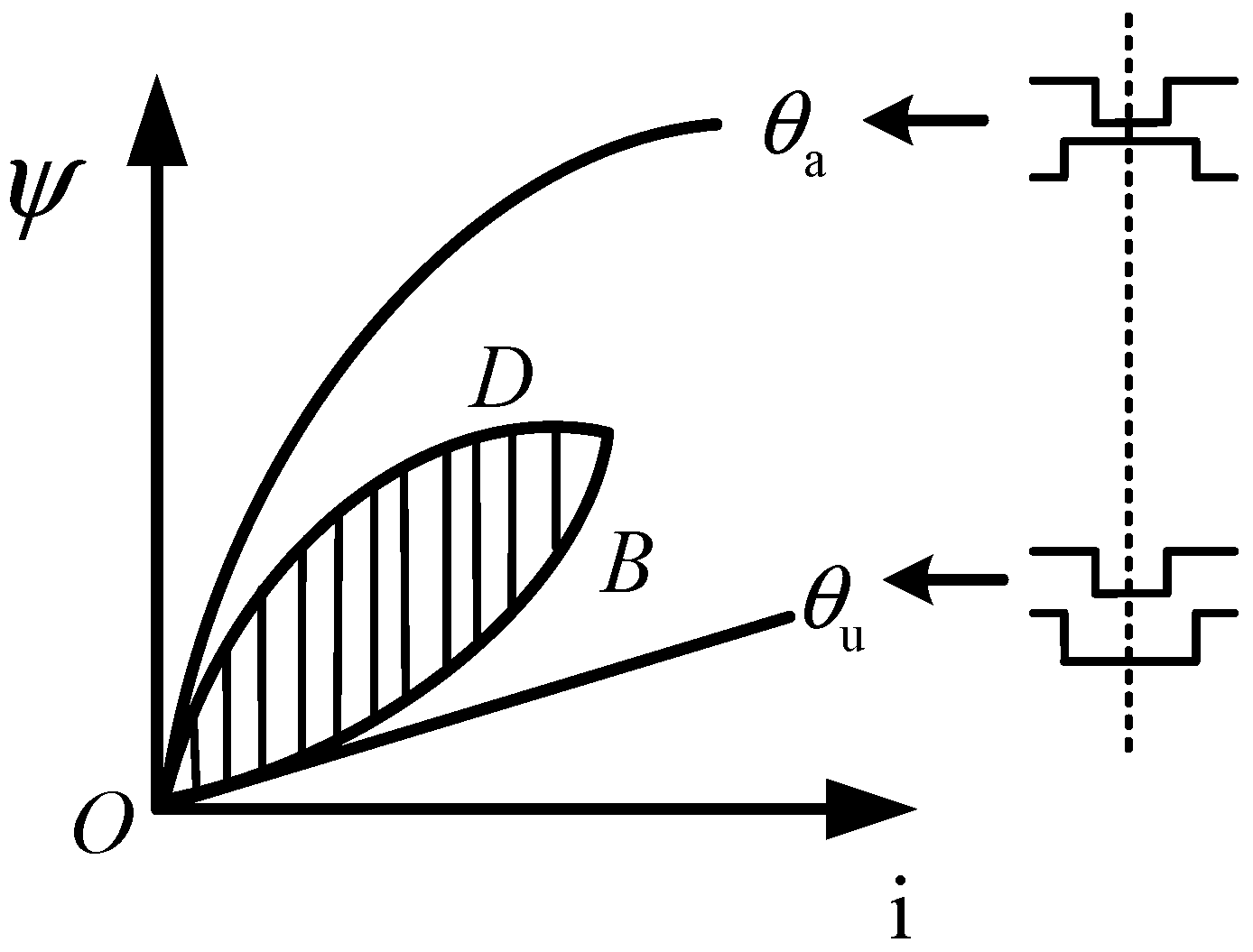
As shown in
Figure 1, since the mutual inductance effect between phase windings is neglected, the electromagnetic torque analysis of SRM can be simplified to a single-phase independent study. The mathematical expression representing the mechanical energy produced by one phase winding over a complete operating cycle is as follows. The instantaneous electromagnetic torque value at any rotor position is derived based on the principle of virtual displacement, and the specific expression is
The average output torque of m-phase SRM can be obtained through an integral operation:
Here, m signifies the phase number; Nr indicates the number of teeth on the rotor.
3. Model Predictive Control of Switched Reluctance Motors
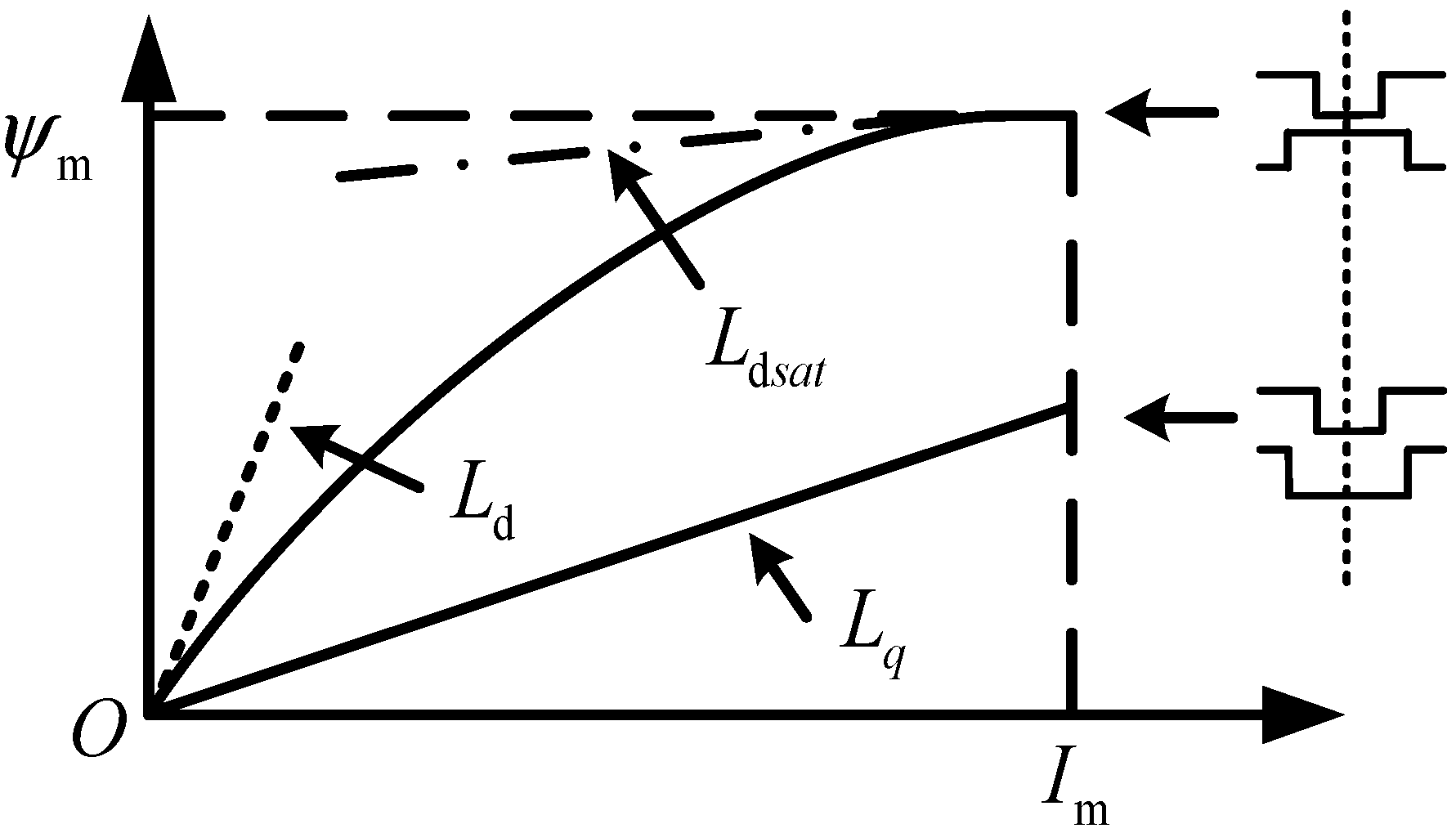
Owing to its extended magnetic path winding configuration, the mutual inductance among different phases in an SRM can be considered negligible.
Figure 2 illustrates the relationship between the magnetic flux linkage and the current for a single phase under this condition.
The phase inductance is at its minimum. The slope of this linear characteristic is defined as the unsaturated inductance
Lq. In the aligned position, consider magnetic saturation. Take the linear inductance before saturation
Ld and saturation inductance
Ldsat as function parameters. Therefore, the following equation describes the flux–current relationship for both the aligned and unaligned positions:
In formulas and , are the magnetic chain and phase currents of the corresponding windings, respectively.
The angle correction expression is
The expression for the magnetization characteristics of the switched reluctance motor is given below:
As defined in Equation (10), the electromagnetic torque is derived from the partial derivative of the magnetic co-energy with respect to the rotor angle, leading to the following expression:
Euler’s method is employed to discretize the switched reluctance motor’s mathematical model across a single sampling interval:
According to Equation (12), it is possible to predict the motor state equation obtained from sampling at moment k and to see the input voltage corresponding to the switching vector selected at moment k + 1, utilizing the predicted current and rotor position for that same time step.
To establish the prediction model, the forward Euler method is employed to discretize the state equations of the motor. The choice of Euler discretization is primarily motivated by two considerations: first, although the electromagnetic dynamics of switched reluctance motors are relatively fast, within the selected control period (Ts; = XX μs), the Euler method approximates the state evolution with sufficient accuracy while maintaining low computational complexity, facilitating real-time implementation; second, the discretized prediction model yields a concise explicit form that facilitates the derivation of the recursive relationships between torque and flux predictions, providing a unified formulation for subsequent multi-step rolling optimization. Based on this discretization, the prediction horizon is defined as N steps. Its relationship with the “long-time-domain” concept introduced in this paper is as follows: conventional predictive torque control typically adopts a single-step or short prediction horizon (N ≤ 3), whereas the proposed approach integrates hysteresis rules with predictive control, enabling the controller to evaluate the cumulative trend of torque errors over N = 5–8 steps. By extending the prediction horizon, the evaluation function can anticipate the evolution of torque deviations under different switching actions, thereby adjusting switching signals proactively under the constraints of the hysteresis bounds. This avoids the myopic behavior commonly associated with short-horizon methods, which often leads to unnecessary switching actions. Within the model, the state prediction terms (flux linkage and current) are used to recursively compute the electromagnetic torque at future time steps. The torque prediction term directly participates in the evaluation function, while the output of the hysteresis comparator serves as the basis for dynamic weight adjustment, allowing the optimization objective to adaptively shift between torque tracking and switching loss reduction under different error intervals. The coordinated interaction of these components constitutes the complete long-time-domain predictive control logic, ensuring that the controller suppresses torque ripple while maintaining system efficiency.
4. Construct MPDTC Speed Controller Design Using Hysteresis Loop Rule
4.1. Power Converters and Sectorization
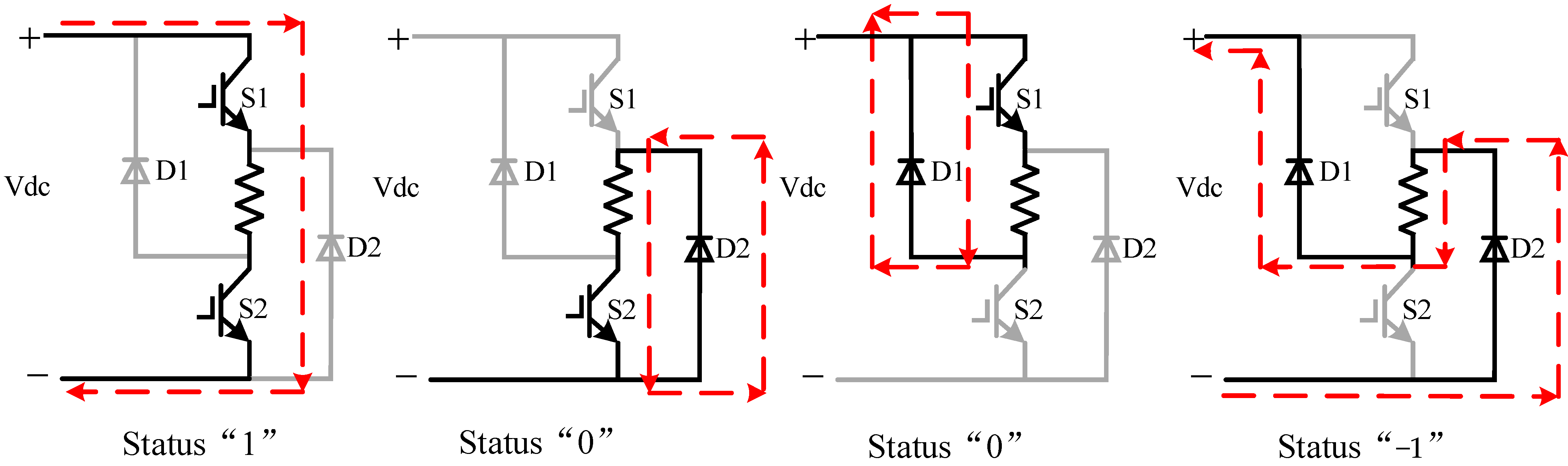
The power converter adopts a three-phase asymmetric half-bridge driving circuit topology, as shown in
Figure 3, where each phase bridge arm consists of two IGBTs and two consecutive diodes. We define the upper and lower bridge arms conduct simultaneously as state “1”: at this point, the motor is in the forward excitation state. The motor operates in a freewheeling state when the upper switch is off and the lower switch is on, a condition denoted as state “0”. Conversely, a reverse demagnetization mode occurs when both the upper and lower switches are turned off simultaneously, which is defined as state “−1”. The switching combinations of the three bridge arms can be represented by a state vector.
As analyzed in the previous section, factors such as magnetic circuit saturation and the eddy current effect lead to the generation of torque pulsations in switched reluctance motors. In addition to this, the selection and division of sectors is also extremely critical for model predictive torque control, and appropriate sector division will reduce the torque pulsation as well as the computational amount of model predictive control. However, when the sector selection is inappropriate, such as the moment of entering a separate phase conduction zone from the phase change zone, the previous phase will provide a negative torque if it is still in the conduction state or the phase current fails to be reduced to less than 0.5 A to 1 A. Given that the total torque in a switched reluctance motor results from the summation of three-phase torques, improper sector definition augments torque ripple and adversely affects control precision. To mitigate this issue, a fuzzy logic-based adjustable sector strategy is introduced. This method dynamically modifies the sector width using current measurements at designated positions, thereby diminishing pulsations caused by negative torque and enhancing overall performance [
15].
This version reorganizes the logic flow to first present the problem of computational complexity, then introduce the sector solution, and finally explain the torque control mechanism, using formal academic phrasing.
Figure 3 indicates that the power converter for each phase possesses three distinct switching states, leading to a total of 27 (3
3) possible switching vector combinations for a three-phase SRM system. Performing predictions for all 27 vectors within one sampling interval would impose a significant computational burden.
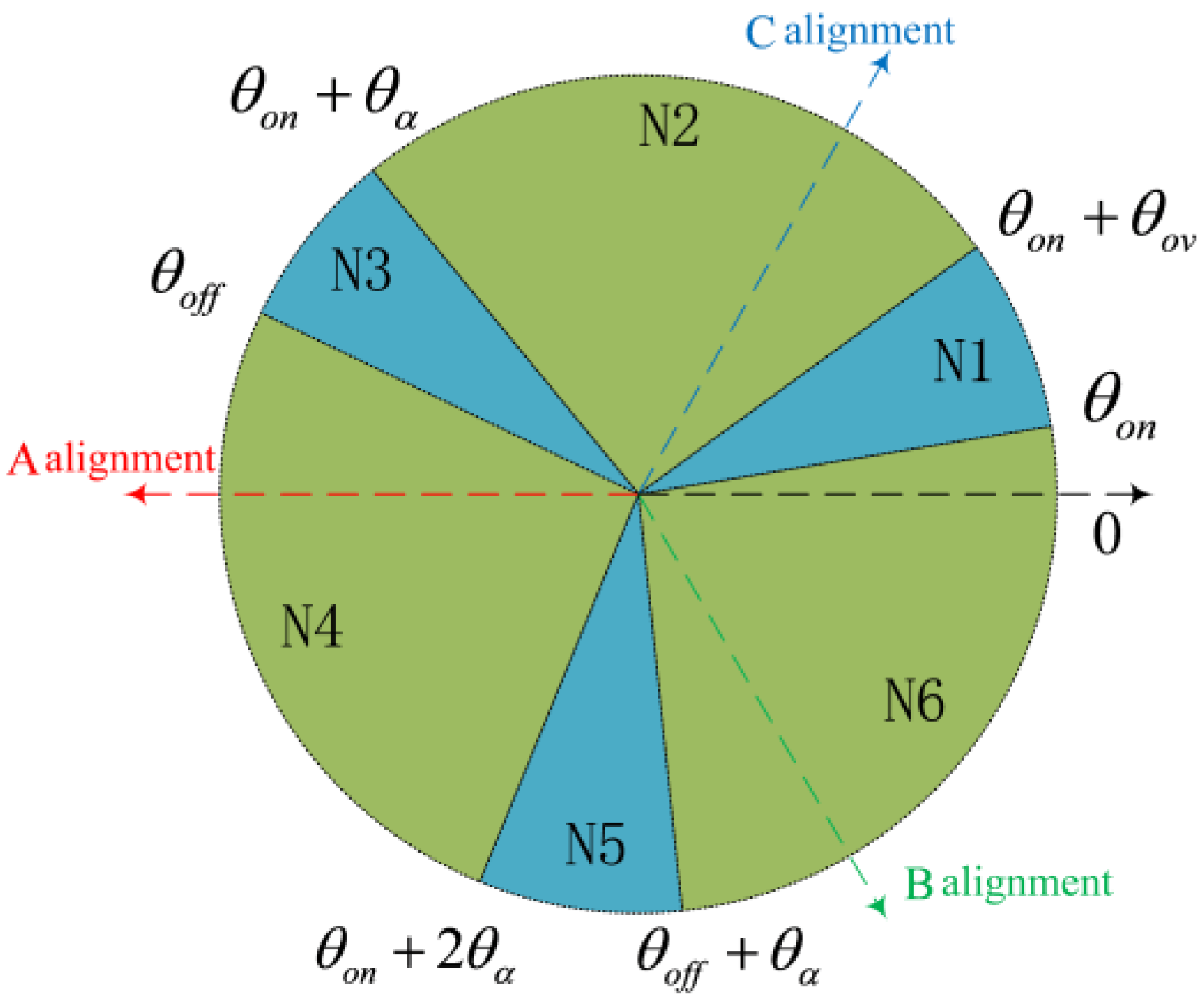
To address this, a six-sector division scheme is implemented, segmenting one electrical cycle of the rotor into six distinct regions. The reference position (0°) is defined when the stator aligns with the center of the rotor notch for phase A, as detailed in
Table 1. Within this framework, torque reduction is achieved via a “soft-chopping” technique, transitioning the bridge arm state from “−1” to “0”. Employing a “hard-chopping” approach by directly selecting state “−1” causes a rapid decay of current in the previously conducting phase. This leads to a sharp drop in torque contribution from that phase before the subsequent phase becomes active, creating a torque deficit. The resultant total torque insufficiency causes noticeable oscillations and pulsations.
Consequently, to minimize computational load, a unique subset of switching vectors is pre-selected for application within each specific sector, significantly reducing the number of candidates evaluated per cycle (see
Table 1).
Traditional model predictive direct torque control (MPDTC) schemes primarily aim to minimize errors in torque and flux linkage tracking when selecting voltage vectors. However, this approach frequently results in elevated switching frequencies and associated power losses. To achieve a better balance between torque ripple suppression and switching loss reduction, the hysteresis band principle commonly found in direct torque control is incorporated into the predictive control framework. As illustrated in
Figure 4, this integration facilitates more a flexible adjustment of the controller’s tracking performance versus switching frequency trade-off, thereby enhancing the system’s adaptability for various operational requirements.
4.2. Introduction of Hysteresis Loop Rules in MPDTC
Following the incorporation of hysteresis regulation, the bandwidth is defined as ±5% of a given torque reference. At sampling instant k, the phase current and rotor position are sampled and fed into the specified equation to compute the instantaneous torque Te(k). This same model is then utilized to predict the state at the next interval, k + 1, providing estimates for the rotor position, phase current, and consequently the torque Te(k + 1).
The Switch Action Vector Set can be determined from the position of the rotor at the
k + 1 moment, with different switching action vectors corresponding to different torque predictions. Take the torque
Te(
k) at moment k and the torque
Te(
k + 1) at moment
k + 1 as a straight line at two points, and, based on the slopes, use linear extrapolation to calculate the length that extends over the range of alternatives when it intersects with the upper limit and the lower limit, as shown in
Figure 5. Optimization Mechanisms Introducing Hysteresis Loop Rules.
The torque extension length within the hysteresis bandwidth is calculated as follows:
is the distance at which the line intersects the upper threshold of the hysteresis band, and is the distance at which the straight line intersects the lower threshold of the hysteresis band.
At this point, the evaluation function can be expressed as
The smaller the calculation result of Equation (15), the better the long-term tracking effect of the given torque, avoiding the traditional tracking control for the given torque tracking repeatedly between the forward excitation and reverse demagnetization state. Therefore, when the torque pulsation suppression effect is better, the switching rate of the power semiconductor is intrinsically lowered, and the switching loss is also smaller. Therefore, the selection of candidate vectors for switching action is performed based on the minimization criterion of the calculated value of the evaluation function.
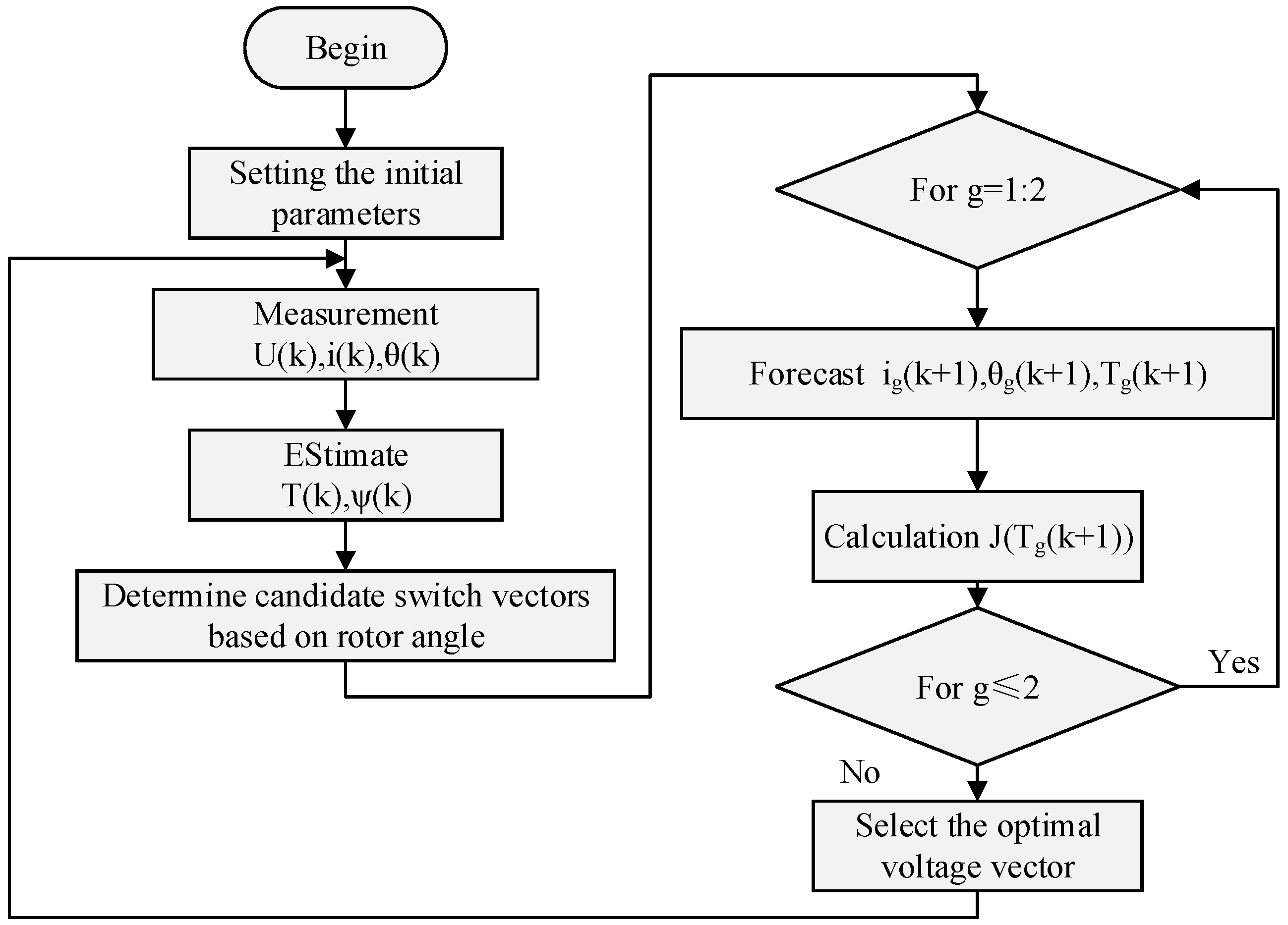
To clearly illustrate the proposed control logic,
Figure 5 presents the algorithmic flowchart. The core mechanism can be summarized as follows. First, based on the current flux linkage, torque, and switching state, the prediction model is used to recursively compute the torque evolution over N future control steps. Second, the hysteresis comparator outputs a status flag according to the current torque error, which dynamically adjusts the weights of the torque tracking term and the switching loss term in the evaluation function. Finally, by minimizing the extension length-based evaluation function (Equation (15)), the optimal switching sequence that maintains the torque error within the hysteresis band for an extended duration is selected. This mechanism embeds the hysteresis rules into the long-time-domain optimization framework, achieving a coordinated optimization of torque ripple suppression and switching loss reduction.
The proposed evaluation function based on torque extension length (Equations (13)–(15)) minimizes the reciprocal of the extension length. The rationale is that maximizing the extension length encourages the torque error to remain within the hysteresis bounds for longer durations, thereby reducing frequent boundary crossings. Minimizing the reciprocal inherently penalizes short extension lengths, which correspond to premature exits from the hysteresis band. In this way, the controller naturally balances torque ripple suppression and switching frequency reduction: longer extension lengths indicate sustained torque tracking with fewer switching actions, while short extension lengths incur a large penalty, implicitly discouraging unnecessary switching. This formulation thus enables the controller to achieve coordinated optimization over an extended time horizon.
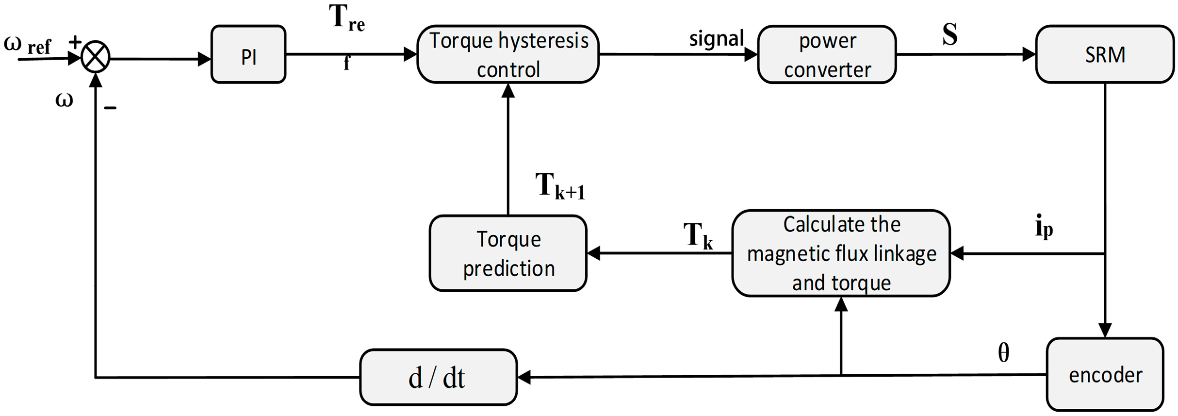
Figure 5 illustrates the complete control system block diagram. The scheme employs a cascaded control structure with speed and torque loops. The speed controller’s input is the velocity error, and its output generates the torque setpoint for the inner loop. Based on the predicted torque, the appropriate switching signal for the next cycle is chosen and designated for the converter.
The control flowchart is shown in
Figure 6:
5. Simulation Analysis
5.1. Simulation Parameters
A simulation model of a 6/4-pole switched reluctance motor was developed within the MATLAB/Simulink environment to assess the performance of the proposed model predictive control strategy incorporating hysteresis regulation. The key motor and simulation parameters are provided in
Table 2 and
Table 3, respectively.
This paper compares the traditional SRM control strategy, Chopper Current Control (CCC), with the more advanced direct instantaneous torque control (DITC). The simulation control parameters for the three algorithms are shown in the table below (
Table 3).
5.2. Simulation Results and Analysis at High Rotational Speeds
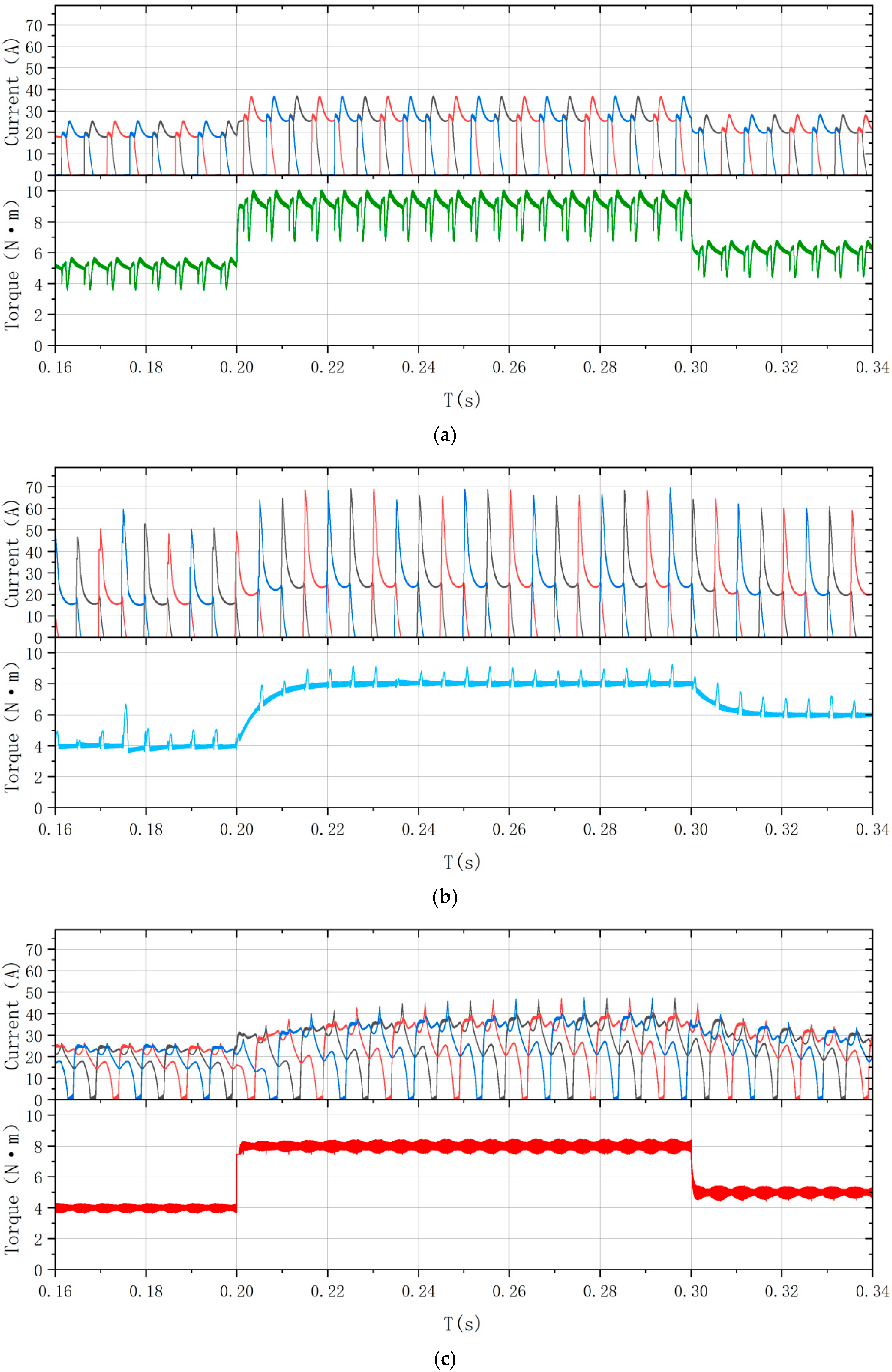
Figure 7 presents the simulated torque and current waveforms under CCC, DITC, and the proposed method, under a constant speed of 1000 rpm and a load torque that transitions sequentially from 4 N·m to 8 N·m, and finally to 6 N·m.
The standard deviation of the torque and torque pulsation factor enables the quantitative evaluation of torque simulation results [
16]:
where
n is the sample size (statistics),
Te represents the electromagnetic torque value at the sampling instant, and
Tav represents the mean value of the electromagnetic torque across a set of n sampling instants.
Tmax, Tmin, and Tav are the maximum, minimum, and average values of torque pulsations, respectively.
The standard deviations of the torque and torque pulsation coefficient for a load torque of 6 N⋅m are shown in
Table 4 and
Table 5.
The data in
Table 4 and
Table 5 show that the standard deviation of the torque of the algorithm is reduced by 0.676 compared to CCC and 0.587 compared to DITC. The torque pulsation coefficient is reduced by 0.138 compared to CCC and 0.115 compared to DITC, which indicates that the algorithm has a better suppression of torque pulsation compared to the conventional algorithm and has a better suppression of torque pulsation and better torque steady state performance at high rotational speeds.
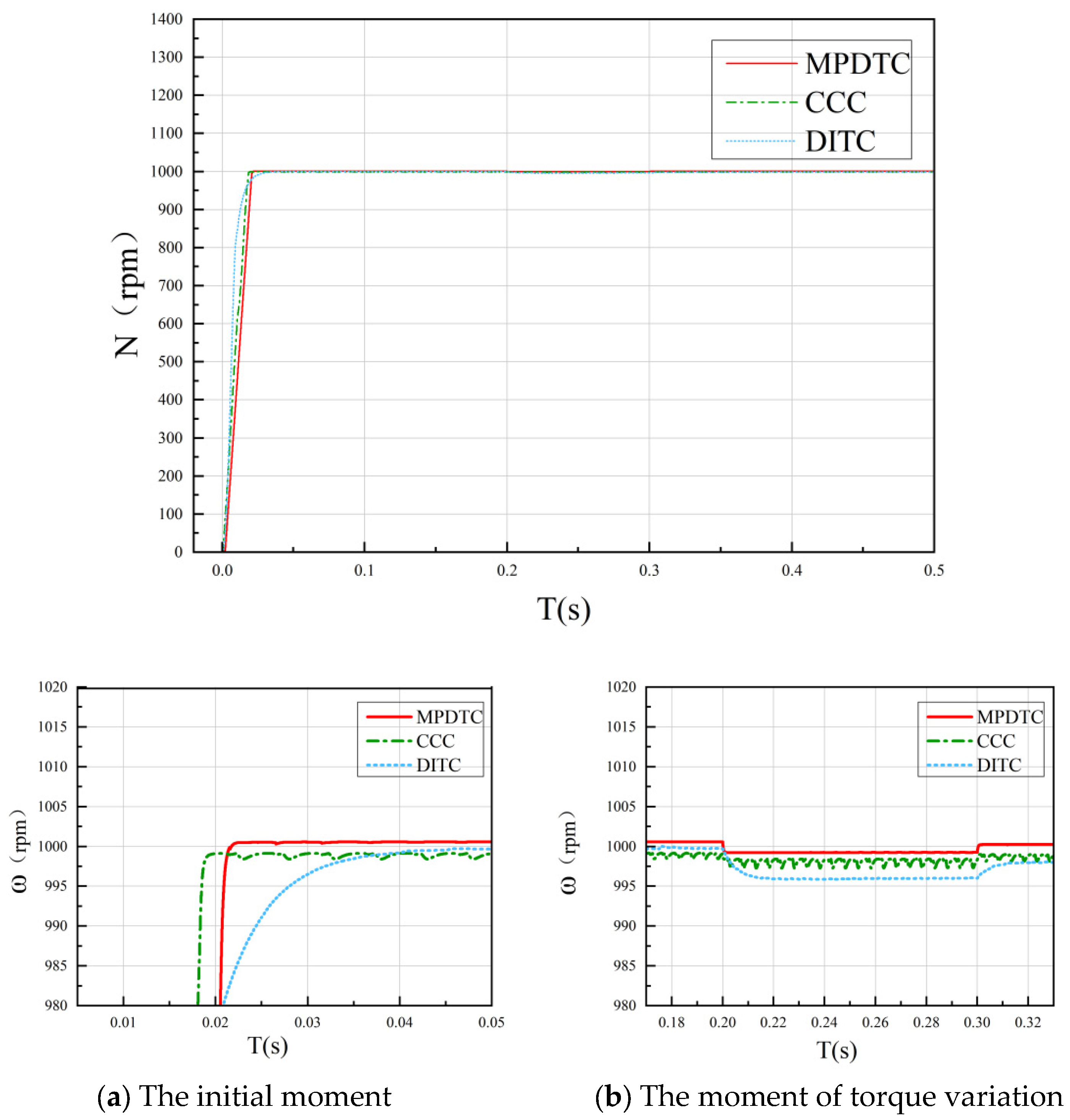
The simulated performance at a fixed speed of 1000 rpm is compared in
Figure 8. Regarding response rapidity, the CCC method demonstrates quicker velocity tracking than both DITC and the proposed approach. Nonetheless, the new algorithm achieves superior precision in steady-state velocity regulation and exhibits minimized fluctuation during abrupt load torque variations, indicating enhanced dynamic stability.
5.3. Simulation Results and Analysis at Low Rotational Speeds
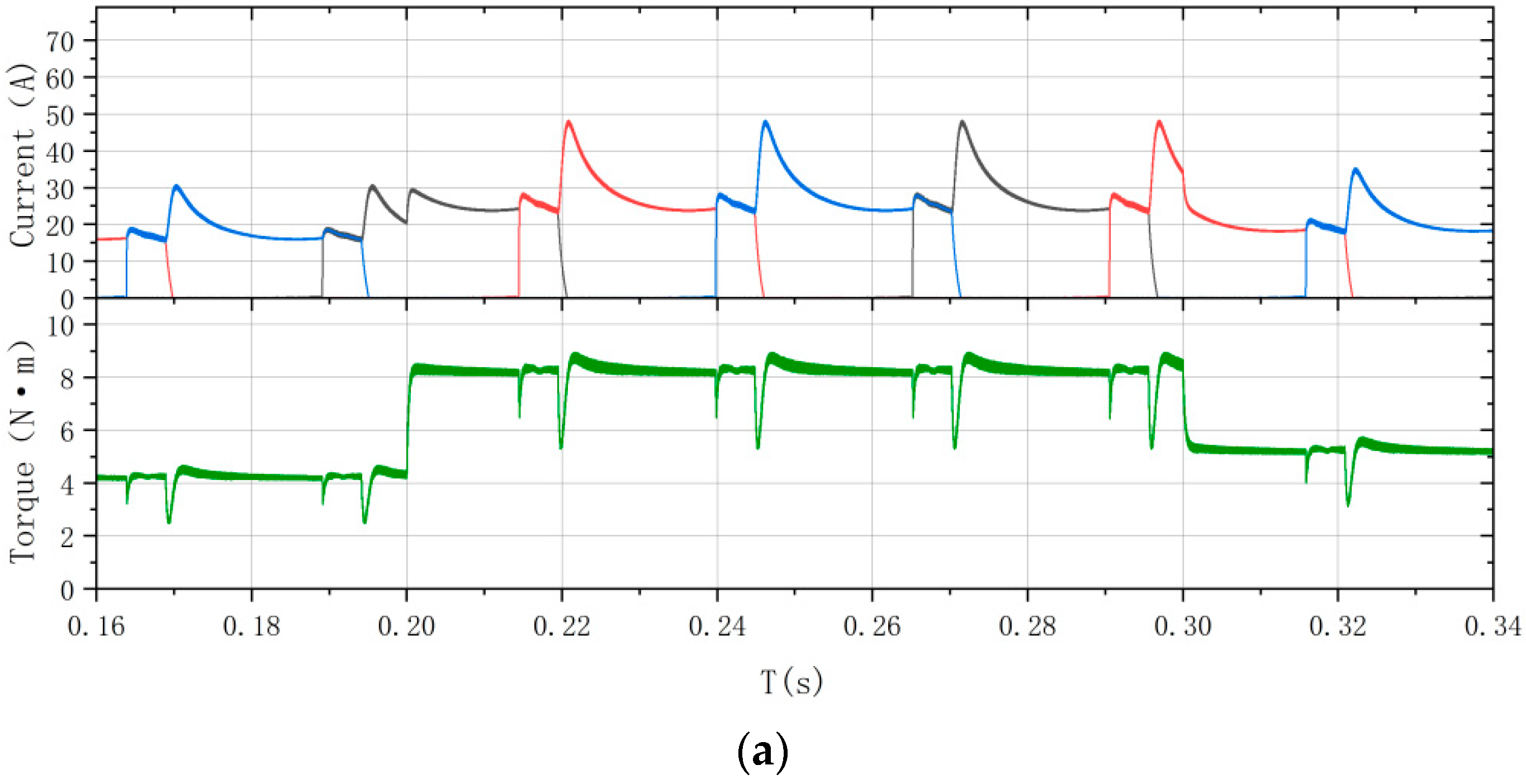
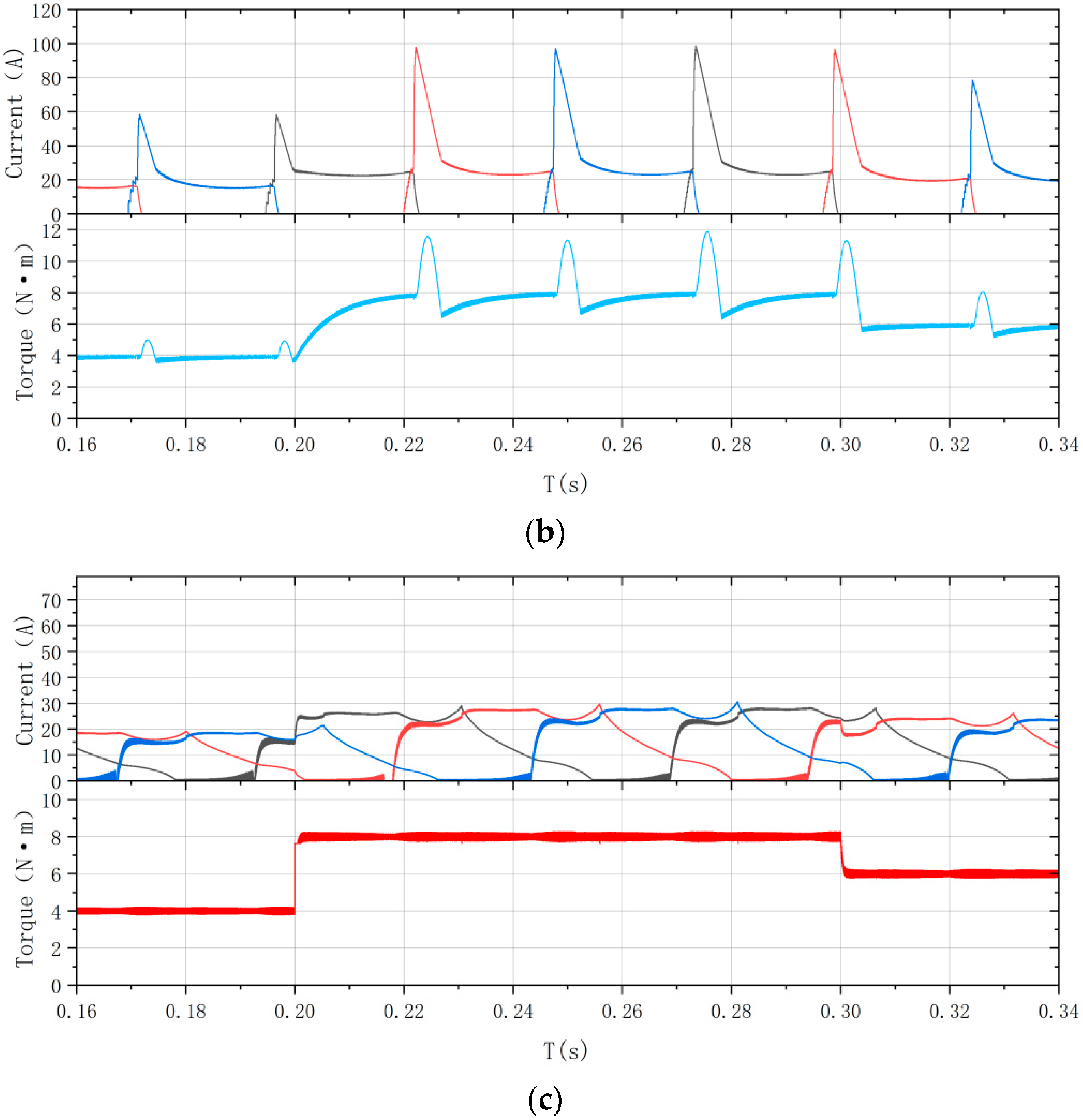
Figure 9 compares the simulated torque and current waveforms for the CCC, DITC, and proposed methods under a low speed of 200 rpm and a load torque that undergoes step changes from 4 N·m to 8 N·m, and finally to 6 N·m.
The standard deviation of the torque and the torque pulsation coefficient for a load torque of 6 N⋅m are shown in
Table 6 and
Table 7.
The data presented in
Table 6 and
Table 7 indicate that the proposed algorithm achieves reductions in torque standard deviation of 0.545 and 0.0373 relative to CCC and DITC, respectively. The corresponding decreases in the torque pulsation coefficient are 0.69 and 1.091, confirming its superior torque steady-state performance and enhanced pulsation suppression capability at low speeds.
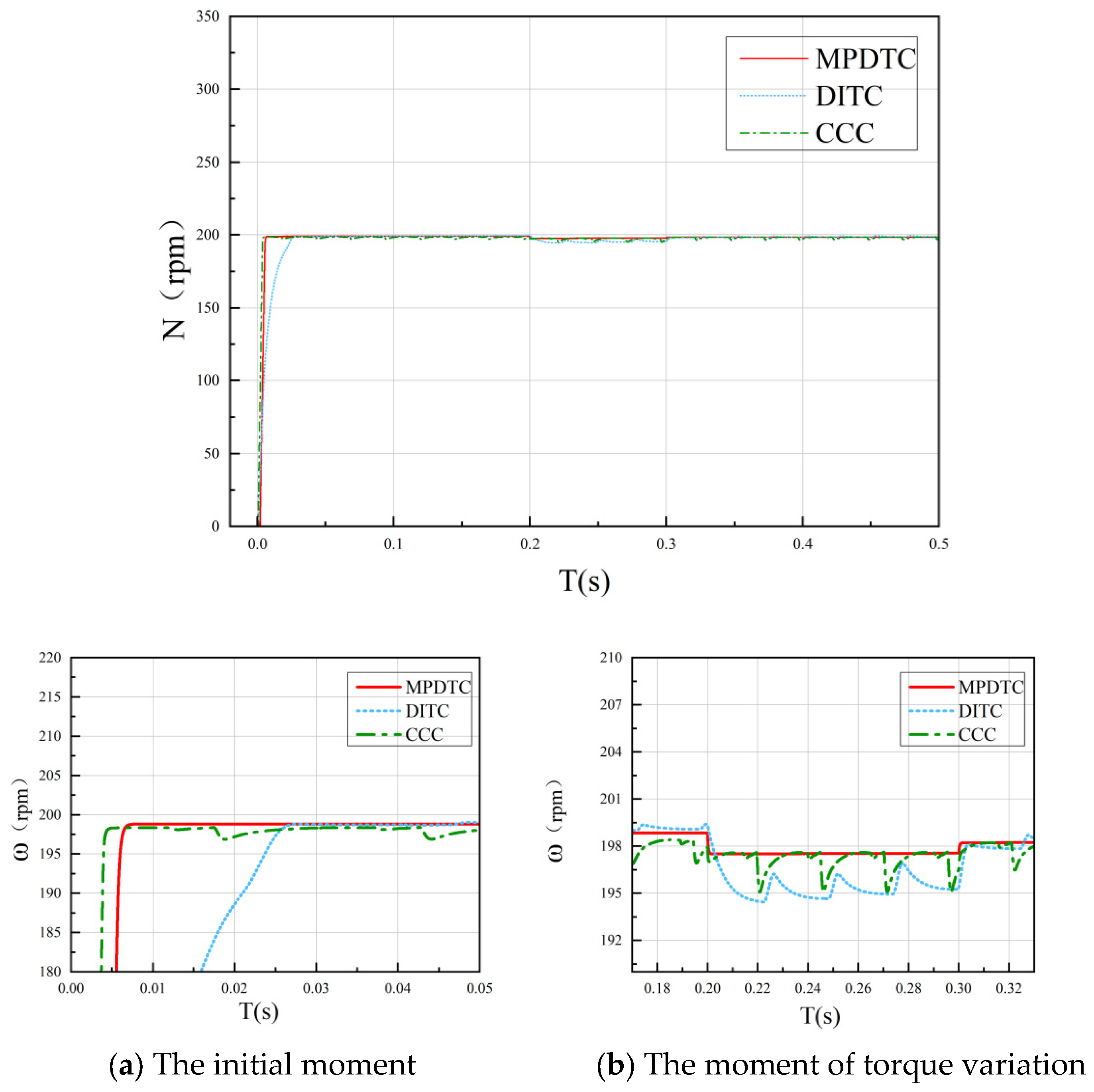
Figure 10 displays the speed response at 200 rpm. CCC and the proposed method exhibit comparable response rapidity, both surpassing DITC. A key advantage of the proposed strategy is the absence of overshoot in the speed trajectory, ensuring stability without compromising responsiveness. Although a marginally larger speed error occurs during low-speed torque transients, the overall difference is negligible. Consequently, the proposed algorithm demonstrates distinct advantages in terms of speed dynamic performance.
6. Conclusions
To enhance the robustness and disturbance rejection capability of switched reluctance motor systems, an improved model predictive direct torque control strategy is developed in this work. The following conclusions are supported by theoretical analysis, simulation results, and experimental tests.
- (1)
At high speeds, the proposed algorithm demonstrates a higher accuracy in speed error compared to conventional methods, exhibits smaller speed fluctuations during load torque transients, and shows a superior dynamic stability. Simultaneously, the torque ripple coefficient and torque standard deviation are significantly reduced, resulting in enhanced steady-state performance. At low speeds, the proposed algorithm and CCC exhibit comparable response speeds, both markedly outperforming DITC. However, the proposed algorithm eliminates overshoot in the speed curve, ensuring rapid response while maintaining superior stability. It effectively suppresses torque ripple and torque standard deviation, demonstrating more pronounced dynamic performance advantages under low-speed conditions.
- (2)
Compared to traditional CCC and DITC algorithms, the proposed algorithm exhibits lower torque ripple across varying speeds and loads, delivering robust performance under diverse operating conditions. From the perspective of the control mechanism, the performance improvements of the proposed method over CCC and DITC can be attributed to the following design features. First, by extending the prediction horizon over multiple steps, the controller anticipates the cumulative trend of torque errors and proactively adjusts switching actions before the torque approaches the hysteresis boundaries, thereby suppressing additional ripple caused by frequent boundary crossings. Second, the dynamic weighting evaluation function enables the optimization objective to adaptively shift between torque tracking and switching loss reduction, avoiding the switching frequency fluctuations commonly associated with fixed hysteresis bands in CCC. Third, the extension length-based penalty mechanism encourages the controller to prioritize switching sequences that maintain the torque within the hysteresis band for longer durations, thereby reducing switching losses without compromising torque quality. These mechanisms collectively explain why the proposed method achieves superior performance over CCC and DITC in terms of both torque ripple suppression and switching frequency reduction under both 1000 r/min and 200 r/min operating conditions.
Author Contributions
M.J., C.L. (Chuanwei Li), X.L. and C.L. (Cheng Liu) contributed to this work as follows: M.J. was responsible for conceptualization, investigation, and visualization; C.L. (Chuanwei Li) contributed to conceptualization, methodology, investigation, and project administration; X.L. (corresponding author) performed validation, wrote the original draft, and contributed to review and editing, as well as supervision; and C.L. (Cheng Liu) contributed to methodology, resources, data curation, and formal analysis. All authors have read and agreed to the published version of the manuscript.
Funding
This study was supported by the National Natural Science Foundation of China under the Top Project: Mechanism of Interfacial Action and Optimized Regulation of Nucleophilic Reagent-Flavanic Acid Chitosan Synergistic Enhancement of Copper-Molybdenum Separation (52174251).
Data Availability Statement
The data are included in this manuscript.
Conflicts of Interest
Authors Meiguang Jiang and Xiangwen Lv were employed by the company Kunming Metallurgical Research Institute Co., Ltd. and the company Mining and Metallurgy Technology Group Co., Ltd. The remaining authors declare that the research was conducted in the absence of any commercial or financial relationships that could be construed as a potential conflict of interest.
References
- Saleh, A.L.; Al-Amyal, F.; Számel, L. Control techniques of switched reluctance motors in electric vehicle applications: A review on torque ripple reduction strategies. AIMS Electron. Electr. Eng. 2024, 8, 104–145. [Google Scholar] [CrossRef] [Scilit]
- Liang, J.; Wang, F.; Feng, J.; Zhao, M.; Fang, R.; Pi, D.; Yin, G. A hierarchical control of independently driven electric vehicles considering handling stability and energy conservation. IEEE Trans. Intell. Veh. 2023, 9, 738–751. [Google Scholar] [CrossRef] [Scilit]
- Liang, J.; Feng, J.; Fang, Z.; Lu, Y.; Yin, G.; Mao, X.; Wu, J.; Wang, F. An energy-oriented torque-vector control framework for distributed drive electric vehicles. IEEE Trans. Transp. Electrif. 2023, 9, 4014–4031. [Google Scholar]
- Siadatan, A.; Fatahi, N.; Sedaghat, M. Optimum Designed Multilayer Switched Reluctance Motors for use in Electric Vehicles to Increase Efficiency. In Proceedings of the 2018 International Symposium on Power Electronics, Electrical Drives, Automation and Motion (SPEEDAM), Amalfi, Italy, 20–22 June 2018; pp. 304–308. [Google Scholar]
- Yuan, Z.; Chen, H.; Zhan, Y. A multi-objective optimization study of a 30 kW switched reluctance motor. Large Mot. Technol. 2023, 15–21. [Google Scholar] [CrossRef] [Scilit]
- Liu, Z.; Chen, M.; Yang, Y.; Liu, C.; Gao, H. A Full-Period Mathematical Model for a Hybrid-Rotor Bearingless Switched Reluctance Motor. Symmetry 2021, 13, 2383. [Google Scholar] [CrossRef] [Scilit]
- Parreira, B.; Rafael, S.; Pires, A.J.; Branco, P.J.C. Obtaining the magnetic characteristics of an 8/6 switched reluctance machine: From FEM analysis to the experiment tests. IEEE Trans. Ind. Electron. 2005, 52, 1635–1643. [Google Scholar] [CrossRef] [Scilit]
- Song, S.J.; Ge, L.F.; Ma, S.J.; Zhang, M.; Wang, L. Accurate measurement and detailed evaluation of static electromagnetic characteristics of swithced reluctance machines. IEEE Trans. Instrum. Meas. 2015, 64, 704–714. [Google Scholar] [CrossRef] [Scilit]
- Ronanki, D.; Williamson, S.S. Comparative analysis of DITC and DTFC of switched reluctance motor for EV applications. In Proceedings of the 2017 IEEE International Conference on Industrial Technology (ICIT), Toronto, ON, Canada, 22–25 March 2017; pp. 509–514. [Google Scholar]
- Song, S.; Liu, J.; Zhao, Y.; Ge, L.; Ma, R.; Liu, W. High-Dynamic Four-Quadrant Speed Adjustment of Switched Reluctance Machine with Torque Predictive Control. IEEE Trans. Ind. Electron. 2022, 69, 7733–7743. [Google Scholar] [CrossRef] [Scilit]
- Xu, A.; Shang, C.; Chen, J.; Zhu, J.; Han, L. A New Control Method Based on DTC and MPC to Reduce Torque Ripple in SRM. IEEE Access 2019, 7, 68584–68593. [Google Scholar] [CrossRef] [Scilit]
- Dejanović, M.; Panić, S.; Kontrec, N.; Đošić, D.; Milojević, S. Neural Network-Based Optimization of Repair Rate Estimation in Performance-Based Logistics Systems. Information 2025, 16, 1031. [Google Scholar] [CrossRef] [Scilit]
- Li, W.; Cui, Z.; Ding, S.; Chen, F.; Guo, Y. Model Predictive Direct Torque Control of Switched Reluctance Motors for Low-Speed Operation. IEEE Trans. Energy Convers. 2022, 37, 1406–1415. [Google Scholar]
- Omar, M.; Bakr, M.; Emadi, A. Switched reluctance motor design optimization: A framework for effective machine learning algorithm selection and evaluation. In 2024 IEEE Transportation Electrification Conference and Expo (ITEC); IEEE: Piscataway, NJ, USA, 2024; pp. 1–6. [Google Scholar]
- Maurya, A.K.; Maheshwari, M.K.; Gupta, A.K. Designing and modelling of switched reluctance motor with its characteristics analysis. In 2024 Fourth International Conference on Advances in Electrical, Computing, Communication and Sustainable Technologies (ICAECT); IEEE: Piscataway, NJ, USA, 2024; pp. 1–6. [Google Scholar]
- Huang, S.; Cao, G.; He, Z.; Pan, J.; Duan, J.; Qian, Q. Nonlinear modeling of the inverse force function for the planar switched reluctance motor using sparse least squares support vector machines. IEEE Trans. Ind. Inform. 2015, 11, 591–600. [Google Scholar] [CrossRef] [Scilit]
| Disclaimer/Publisher’s Note: The statements, opinions and data contained in all publications are solely those of the individual author(s) and contributor(s) and not of MDPI and/or the editor(s). MDPI and/or the editor(s) disclaim responsibility for any injury to people or property resulting from any ideas, methods, instructions or products referred to in the content. |