Article

Study on Coordinated Control Strategy of Multi-Pass Straight Drawing Machine System

School of Electrical and Information Engineering, Beihua University, Jilin 132000, China
*
Author to whom correspondence should be addressed.
Energies 2026, 19(7), 1798; https://doi.org/10.3390/en19071798
Submission received: 22 January 2026 / Revised: 10 March 2026 / Accepted: 19 March 2026 / Published: 7 April 2026
(This article belongs to the Special Issue Design and Control of Power Converters)

Abstract

To address the issues of poor control performance, synchronization defects, and instability in existing multi-pole permanent magnet synchronous motor (PMSM) control systems using PI control, this paper proposes an optimized control strategy combining Linear Active Disturbance Rejection Control (LADRC) with Capuchin Search Algorithm (CapSA). The proposed approach first implements LADRC in the PMSM speed loop, where the CapSA algorithm is applied to tune LADRC parameters, significantly reducing overshoot, enhancing the disturbance rejection capability, and improving the system stability. Secondly, by modifying the traditional deviation coupling structure and introducing an error factor to strengthen dynamic synchronization performance among multiple motors, the system’s control accuracy and robustness are effectively enhanced. Finally, a simulation model is established using MATLAB/Simulink for comparative experiments under various operating conditions. The results demonstrate that the proposed CapSA-LADRC control strategy significantly reduces speed overshoot and synchronization errors while exhibiting superior dynamic response and disturbance rejection capabilities, providing a reliable solution for practical engineering applications.

1. Introduction

With the continuous advancement of intelligent manufacturing, traditional motor control systems can no longer meet modern industrial demands for high-performance equipment. Consequently, multi-motor coordination control systems have become a key focus in industrial research. Drawing machines are evolving towards automation, digitalization, and intelligence while pursuing high-speed operation, efficiency, quality, and energy conservation. In the multi-pass straight-in wire drawing machine, each drum is equipped with an independent motor, which is linked with the frequency converter through the PLC to increase the rotation speed step by step according to the elongation rate, forming a stable pulling force with the speed difference, and real-time fine-tuning with the tension closed-loop to achieve the high-precision synchronization of multiple motors and continuous drawing of constant tension. Currently, multi-pass linear drawing machines typically use AC induction motors with variable frequency drives (VFDs) for speed regulation. However, these systems exhibit limited precision and performance instability under load fluctuations, hindering intelligent development. In contrast, permanent magnet synchronous motors (PMSM) demonstrate advantages such as high torque at low speeds and a superior power factor. These motors enable the direct drive of drawing machines, enhancing transmission efficiency and reliability while facilitating smart control implementation.
In multi-motor drive systems of multi-pass straightening machines, simultaneous operation of multiple motors often leads to asynchronous rotation and even motor damage. To address this issue, researchers worldwide have proposed various advanced control methods and strategies. For instance, Hu Jiajun [1] developed a neural network control strategy that achieved precise PMSM speed tracking, though the system remains complex. Wu Weizhen [2] designed a model predictive speed controller that improved PMSM’s steady-state performance and dynamic response but required substantial computational resources. Yu Baiqiang [3] combined adaptive control with PI control to enhance system robustness against load fluctuations, though implementing adaptive control necessitates precise mathematical modeling of PMSMs, which complicates both modeling and computation. GAO et al. [4] proposed a bandwidth-based Linear Active Disturbance Rejection Control (LADRC), which effectively simplifies the steps of parameter tuning and the difficulty of theoretical analysis. ZHU et al. [5] designed a new Linear Active Disturbance Rejection Control (NLADRC) to further enhance the robustness of the motor drive system against disturbances by incorporating a cascade structure, but the stability analysis of the controller is more complex. By replacing controllers in the PMSM speed loop with self-disturbance rejection controllers [6,7], system modeling complexity is reduced as it eliminates dependence on controlled object models. When subjected to internal or external disturbances, these controllers enable dynamic compensation for rapid speed response while reducing overshoot and improving control accuracy, though they involve multiple parameters that are challenging to tune. Ding Wei [8] and colleagues enhanced multi-motor synchronization precision through mean coupling based on deviation coupling, but this structure is susceptible to load variations. Ye Yuhao [9] integrated cross-coupling and deviation coupling advantages to improve disturbance rejection for four motors but faced limitations, including error delay and computational overhead. Zhu Bo [10] established the coupling relationship between the speed and position of two motors based on the cross-coupling principle, and quickly compensated the action error of dual motors through a synchronous compensator. However, the cross-coupling control strategy is only applicable to a dual motor system.
To address the limitations in current research on multi-PMSM speed control strategies and synchronization control methods, as well as the advantages of Linear Active Disturbance Rejection Control (LADRC) in anti-interference capability and speed regulation, this study adopts a Linear Active Disturbance Rejection Controller (LADRC) with a simpler structure and fewer adjustment parameters. Since obtaining appropriate controller parameters is both time-consuming and challenging, and since improper parameter settings may compromise system performance—while manual parameter tuning for LADRC proves complex and ineffective [11]—developing precise and convenient parameter adjustment methods becomes imperative. The Capuchin Search Algorithm (CapSA), a novel intelligent optimization algorithm, is employed in this research for its strong optimization capabilities and rapid convergence speed. This study applies PI, LADRC, and CapSA-LADRCs to PMSM system speed loop control while using a PI controller for current loop torque regulation. MATLAB 2024a simulations demonstrate the effectiveness and convergence of these three controllers in PMSM systems.

2. Establishment of Multi-Pass Straight Drawing Machine and Permanent Magnet Synchronous Motor Model

2.1. Overall Structure of Straight Drawing Machine System

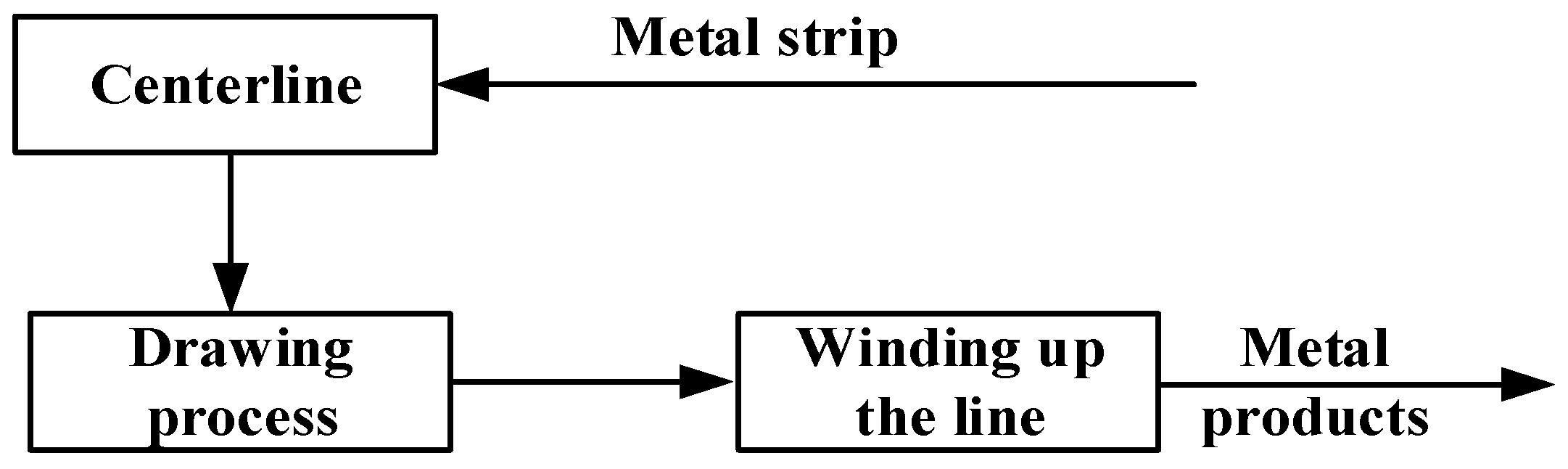
The wire drawing machine operates through three core components: wire unwinding, wire drawing, and wire winding. These interconnected stages form the essential workflow of the equipment, each governed by specific control parameters and influencing factors. Effective coordination across these phases ensures stable machine operation and maintains high production quality as shown in Figure 1.
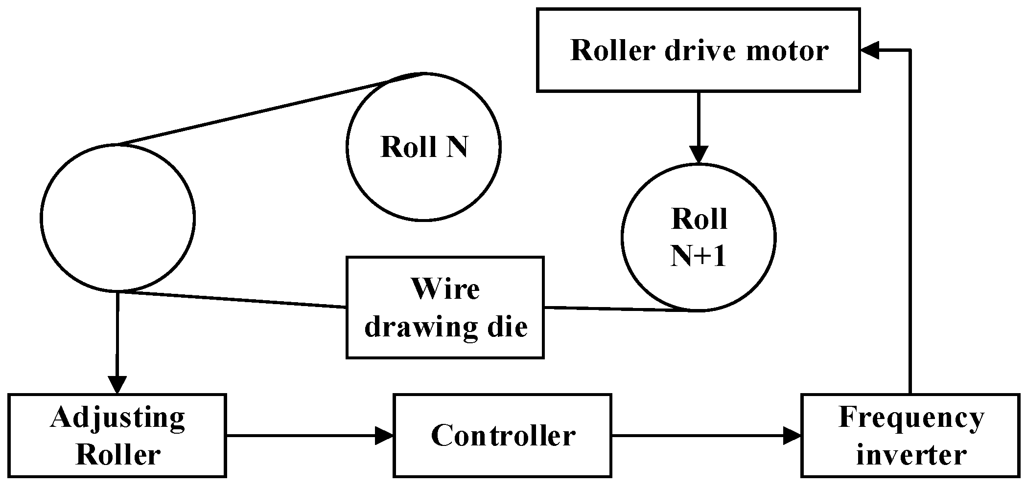
Generally speaking, the straight drawing machine is composed of a reel, frequency converter, tension arm, drawing die, adjusting roller and so on (see Figure 2).
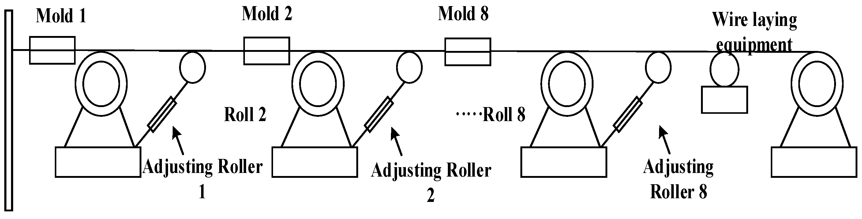
Theoretically, the system can operate stably by pre-calculating and setting key parameters like transmission ratios and speed ratios as illustrated in Figure 3. However, in real-world production, factors such as mechanical errors, wear, and voltage fluctuations often disrupt speed synchronization between reels. This imbalance in wire tension may cause line accumulation or wire breakage, disrupting normal operations. Therefore, maintaining strict motor synchronization is absolutely critical.

2.2. Mathematical Model of Permanent Magnet Synchronous Motor

The PMSM mathematical model is characterized by nonlinearity and strong coupling. When studying PMSM control, factors with minor influence such as core saturation, eddy currents, and hysteresis losses can be neglected [12,13]. Considering only the symmetrical configuration of each winding, the state equations of the rotor d-q axis in the rotating coordinate system are:
i d ˙ i q ˙ ω ˙ m = R s L d n p ω m 0 n p ω m R s L q n p ψ f L q 0 T e i q J B J i d i q ω m + u d L d u q L q T L J
In the equation, i d , u d , and L d represent the d-axis components of stator current, voltage, and inductance, respectively; i q , u q , and L q represent the q-axis components of stator current, voltage, and inductance, respectively; R s is the stator resistance; ω m is the mechanical angular velocity; ψ t is the rotor permanent magnet flux linkage; T L is the load torque; J is the moment of inertia; B is the motion damping coefficient; n p is the number of motor pole pairs; T e is the electromagnetic torque. PMSM electromagnetic torque:
T e = 1.5 n p Ψ t i q + L d L q i d i q
Therefore L d = L q , and Equation (2) can be simplified as:
T e = 1.5 n p Ψ t i q
When the i d = 0 , control strategy is adopted. The state equation of PMSM is transformed into:
i q ω ˙ m = R s / L q n p Ψ t / L q 1.5 n p Ψ t / J B / J i q ω m + u q / L q T L / J
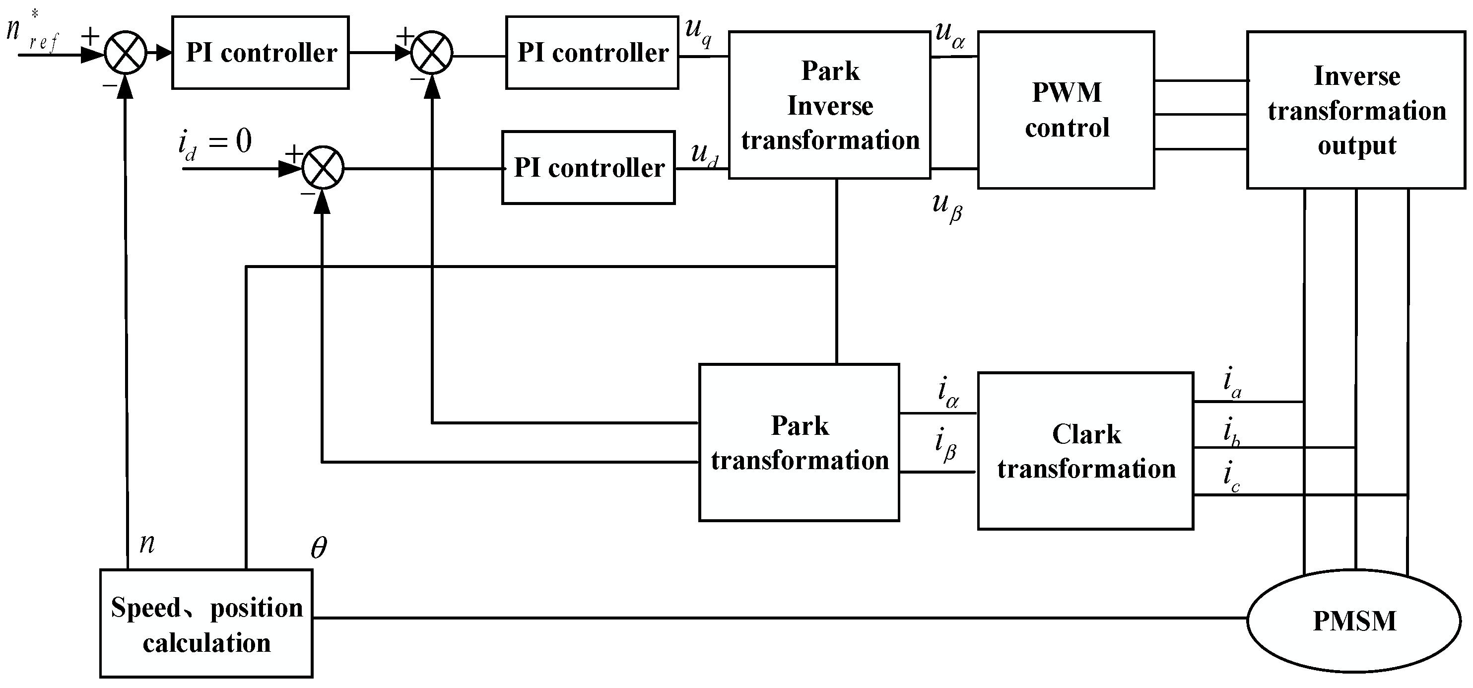
The dual closed-loop PMSM control model adopted in this paper is the speed outer ring and the current inner loop, respectively. Figure 4 shows the PMSM vector control structure, with n r e f *   a n d   n being the actual rotation speed and speed expectation, respectively.

3. Research and Design of Control System Algorithm for Multi-Pass Straight Drawing Machine

3.1. First-Order Linear Self-Disturbance Rejection Control

3.1.1. Structure

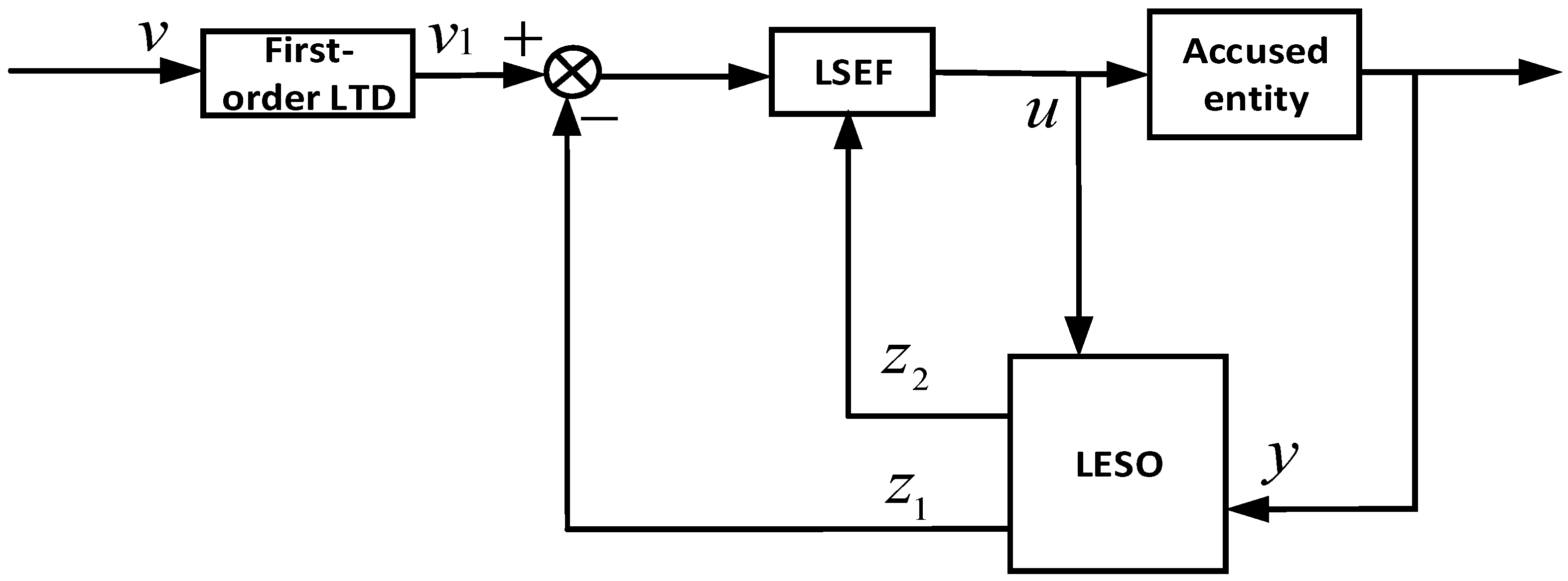
The first-order LADRC is shown in Figure 5. The Linear Extended State Observer (LEO) module serves as a linearly extended state observer, the Linear Tracking Differentiator (LSEF) module functions as a linear state error feedback controller, and the first-order Linear Tracking Differentiator (LTDR) acts as a linear tracking differentiator. This controller converts nonlinear systems with unknown disturbances into linear series-integral configurations. The estimation and compensation mechanisms address total system disturbances, including both internal and external interference.

3.1.2. Basic Algorithm

In a first-order system, y is the output velocity. LTD transfer function:
v 1 s v s = 1 1 T s + 1
where v 1 : is the tracking signal; v is the target velocity; T is the time constant; and s is the Laplace operator. LESO function:
e = Z 1 y , Z ˙ 1 = Z 2 + b 0 u β a e , Z ˙ 2 = β b e ,
In the above equation, e represents the error between the observed estimated signal and the actual output signal; Z 1 is the observation and estimation signal of the system state and; Z 2 is the estimated value of the total disturbance of the system. b 0 is the disturbance compensation factor; a ,   b is the gain coefficient of the Linear Expansion State Observatory (LESO); and u is the output of the controller.
u = k p v 1 Z 1 Z 2 / b 0 ,
where k p is the proportion coefficient.

3.2. Linear Self-Disturbance Control Design of Permanent Magnet Synchronous Motor

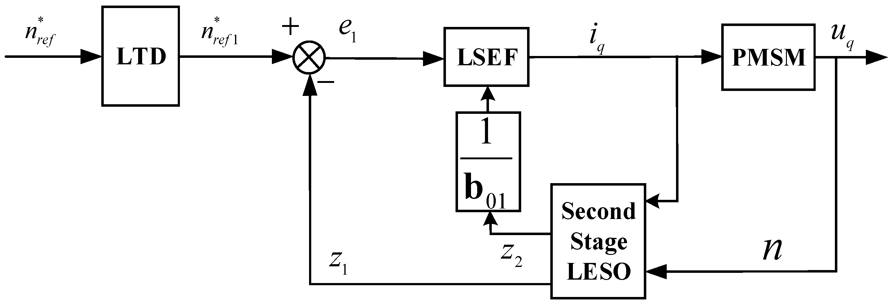
In the PMSM speed control system, internal and external disturbances affect the speed loop control. Figure 6 shows the structure of the speed loop using LADRC. According to the linear control theory in the literature [14], it can be obtained that:
ω ˙ m = 1.5 n p ψ f i q / J T L + B ω m / J
Let b 01   =   3 n p ψ f / 2 J represent the current gain of the velocity loop controller and f T L ,   ω m ,   B ,   t = T L + B ω m / J represent the internal and external disturbances of the entire system; then, Equation (8) can be rewritten as
ω m = b 0 i i y + f T L , ω m , B , t
According to Equation (9), the linearly expanded x 1 = ω m , x 2 = f T L , ω m , B , t , x ˙ 2 = f state observer is designed. We can obtain the state equation of the system:
y = x 1 , x ˙ 1 = x 2 + b 0 i i y , x ˙ 2 = f ,
In the formula, x 1 x 2 is the state variable of the system. The linearly extended state observer spatial equation is:
x ˙ = A x + B i q + E f , y = C x .
x = x ˙ 1 x ˙ 2 , B = b 0 i 0 , E = 0 1 , C = 1 0 ,
A = 0 1 0 0
According to the classical linear expansion state observer principle, the observation model can be obtained as follows:
e = Z 1 n , Z ˙ 1 = Z 2 + b 0 i i q β e e , Z ˙ 2 = β h e .
Linear error state feedback controller function [15]:
u = k p n m d + Z 1 Z 2 / b 0 i
According to the method in [16], the ω c ω o system bandwidth and state observer bandwidth are introduced, and the pole configuration of Equation (14) is performed in a linear manner. The characteristic equation is
p s = s 2 + β a s + β b .
The β a β b ω o ω o > 0 is represented by:
β a = 2 ω o , β b = ω o 2 , k p = ω o .
Typically, ω 0 = ( 3 10 ) ω c and ω c = ( 8 10 ) / t s . In this paper, t s = 0.1   s and ω c = 10 / t s . The parameters of the LADRC are usually initially set using bandwidth tuning, followed by manual adjustment. However, the parameter values for the LESO and LSEF can differ significantly from those based on bandwidth tuning. Therefore, the LADRC has three parameters that need tuning, including β a , β b , and k p . Moreover, obtaining suitable controller parameters through manual tuning is difficult. This paper employs the CapSA to automatically tune the controller parameters, enabling the PMSM system to achieve better performance.

3.3. Parameter Tuning Principle Based on CapSA-LADRC

3.3.1. Principle of Adjusting LADRC Parameters Based on the CapSA Algorithm

When the i d = 0 control strategy is adopted, the output torque is entirely provided by the q-axis current, which is controlled by the LADRC speed loop. This results in smoother output speed, faster response, and stronger disturbance rejection capability for the system. The performance of the LADRC largely depends on its parameters. Among them, β 2 and β 6 play important roles in tracking system state variables and observing internal and external disturbances. Furthermore, b 01 is related to the controlled plant and k p is related to the control speed. The LADRC requires a relatively optimal set of parameters to be found to enhance system stability.
Particle Swarm Optimization (PSO) is prone to falling into local optimal solutions. In the tuning of multiple parameters (βa, ββ, Kp), it is likely to cause the parameters to converge to local optima, resulting in insufficient control performance of LADRC. The Whale Optimization Algorithm (WOA) has a relatively slow convergence speed and cannot meet the real-time requirements of multi-motor control for wire drawing machines in the real-time parameter tuning of industrial control. Reinforcement Learning (RL) requires extensive sample training and reward function design, leading to a highly complex system and enormous computational load; moreover, it has high hardware computing power requirements, making it difficult to implement in the industrial field of wire drawing machines. The tuning parameters (βa, ββ, Kp) of LADRC are continuous values, and CapSA achieves higher optimization accuracy for continuous parameters. Additionally, its characteristic of adaptive switching between local and global search can balance the accuracy and efficiency of parameter tuning, which is highly matched with the control requirements of LADRC for “both fast response and high anti-disturbance capability”.
Therefore, this paper applies the CapSA algorithm to optimize the LADRC parameters, making the system state variables and disturbance estimates closer to their true values, thereby improving the control performance.

3.3.2. CapSA Algorithm Principle

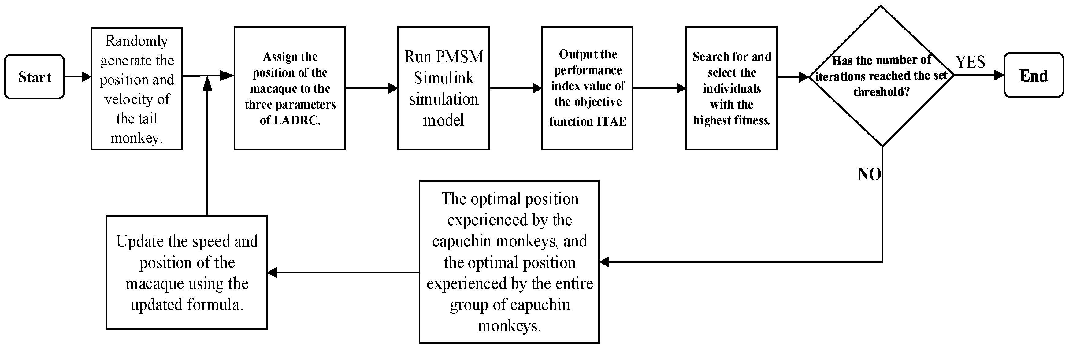
This paper employs CapSA [17] to address constrained and global optimization problems. The algorithm’s design draws primary inspiration from the behavioral dynamics of capuchin monkeys, whose foraging behaviors include tree climbing, ground leaping, swinging, and grasping. These movements are mathematically summarized through position update formulas within the algorithm framework.
(1)
Jumping on trees
αA capuchin monkey can jump from one tree to another, or from one branch to another on the same tree. In this case, the position of the capuchin monkey can be represented as
x j i = F j + P b f v j i 2 s i n 2 θ / g , i < N / 2 ; 0.1 < ε 0.20 ,
where x i is the position of the alpha capuchin and other capuchins in the j -th dimension; F j is the position of the food in the j -th dimension; e is a random number uniformly generated within [0, 1]; P bf is the probability of the capuchin providing balance during a jump; g is the gravitational acceleration, with a value of 9.81; θ is the jumping angle of the capuchin; v i is the velocity of the i -th capuchin in the j -th dimension; and N is the number of capuchins. The following refers to the velocity of the i -th capuchin in the j -th dimension:
v j i = ρ v j i + γ a 1 x b e s t j i x j i + γ a 2 F j x i j ,
where γ is the life parameter; x best is the best position of the i -th capuchin in the j -th dimension; and a 1 and a 2 are two positive constants that control the influence of x best and F i on the capuchin’s velocity, both with a mean value of 1. The inertia coefficient ρ controls the influence of the previous velocity on the movement and is set to 0.7.
(2)
Ground jumps
In order to search long distances in areas where food is scarce, capuchin monkeys use ground jumps to move. The new position of the leader and the following capuchin monkey can be determined:
x j i = F j + P b f P e f v j i 2 s i n 2 θ / g , i < N / 2 ; 0.2 < ε 0.30 ,
where P e f is the elastic probability of the tail monkey moving on the ground; and P b f , P e f are the elastic coefficient and the balance coefficient, respectively, which can improve the efficiency of local and global search. After in-depth analysis, they are determined to be 0.7 and 9.
α New position of the rolling monkey during normal walking:
x j i = x j i + v j i , i < N / 2 ; 0.3 < ε 0.50 .
(3)
Swinging motion
Some α woolly monkeys and other associated species may search for food by walking short distances and using local search on all the tips of branches. They grasp branches with their tails and look for food by shaking them from side to side. In this case, the position of the woolly monkey can be determined as follows:
x j i = F j + γ P bf s i n 2 θ , i < N / 2 ; 0.5 < ε 0.75 .
(4)
Climbing
During foraging, the α meerkat and other following meerkats may climb trees and come down repeatedly, a process similar to local search. In this case, the meerkat’s position can be determined as follows:
x j i = F j + γ P bf v j i v j 1 i , i < N / 2 ; 0.75 < ε 1.0 ,
where v j 1 i i j is the previous velocity of the i-th dimension after the end of the first volume.

3.3.3. Implementation of the CapSA Algorithm in LADRC

This paper employs the CapSA algorithm to optimize the parameters of a first-order LADRC in the PMSM speed control system [18]. First, the upper and lower bounds are defined. An approximate range is selected for the LADRC parameters β a , β b , and k p . The parameter b 01 = 3 n p ψ f / ( 2 J ) . The reciprocal of the Integral of Time-weighted Absolute Error (ITAE) performance index is used as the fitness function for the algorithm in this paper. ITAE is selected to describe the system performance; a smaller ITAE value indicates better system performance.
I T A E = 0 t | n r e f * n | d t .
Since the constraint condition adopted in this paper is the minimum value of the objective function, the fitness described in the algorithm should be the inverse of ITAE to obtain the fitness value:
f ( t ) = 1 I T A E = 1 0 t | n r e f * n | d t
The search algorithm flow of the roller monkey is shown in Figure 7.

4. Structural Design of Multi-Motor Coordination Control System

4.1. Bias Coupling Control Structure Analysis

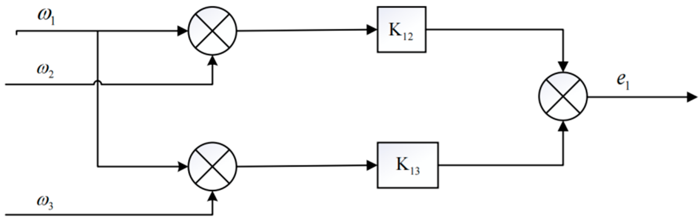
Figure 8 shows the traditional deviation-coupled speed compensator structure, and its basic working principle is as follows: First, ω i , the difference between the speed of the first motor and the speed of the other motors, is calculated; Subsequently, each difference is multiplied by its corresponding feedback gain, K i j ; Finally, all the weighted differences are summed and fed back to the main controller as compensation [19,20,21].
Among K 12 K 13 is the speed feedback coupling gain corresponding to the motor, which is derived from the comparison of the corresponding moment of inertia as mentioned above:
K a b = J a J b
In the formula, J a is the moment of inertia of the control motor and J b is the moment of inertia of the comparison motor used for comparison with the rotational speed of the control motor. From the figure, the expression for the compensation signal e 1 can be derived as:
e 1 = K 12 ω 1 ω 2 + K 13 ω 1 ω 3
This structure has a limitation: it employs fixed gain values for speed compensation. While this approach can achieve zero relative velocity compensation in certain scenarios, significant system load disturbances may cause substantial motor speed fluctuations. This results in prolonged compensation periods and synchronization errors between motors, which frequently lead to operational issues in practical production applications.

4.2. Improvement of Deviation Coupling Structure Design

This paper studies the synchronization of three different motors. Since this synchronization compensation method only considers the ξ i synchronization relationship between the controlled motor and other motors, this paper introduces an error factor, which is defined as follows:
ξ i = 2 ω n ω m a x + ω m i n / 2 i = 1 n ω n n
where e i is the error factor of the i -th unit, ω m a x is the maximum speed of the controlled motor, ω m i n is the minimum speed, and ω ¯ is the average value of the PMSM output speed.
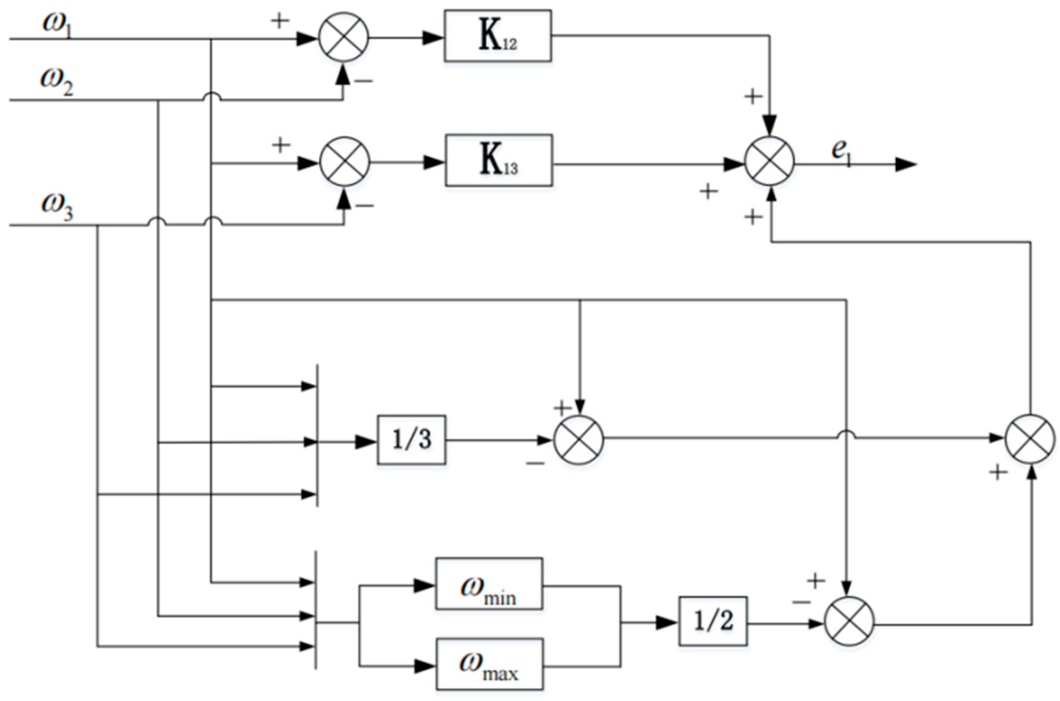
Therefore, the improved speed synchronous error compensator can be expressed by the following formula, and its schematic structure is shown in Figure 9.
e 1 = K 12 ω 1 ω 2 + K 13 ω 1 ω 3 + ξ 1
The improved synchronous error compensator can better combine the tracking error and synchronous ξ i error of multiple motors, and the increased error factor can couple the speed of four motors together, effectively avoiding the influence of excessive speed difference between the four motors on the compensation effect, making the speed compensation more accurate and improving the coordinated control effect.
For the multi-motor coordinated control structure, whether the motor speed or position is used as the compensation quantity and negatively fed back to the speed ring controller, it is intended to compensate the shaft current so that multiple different motors have good synchronous performance during start-up, load removal and load increases.

5. Simulation Experiment and Result Analysis

5.1. Single Motor Control Simulation

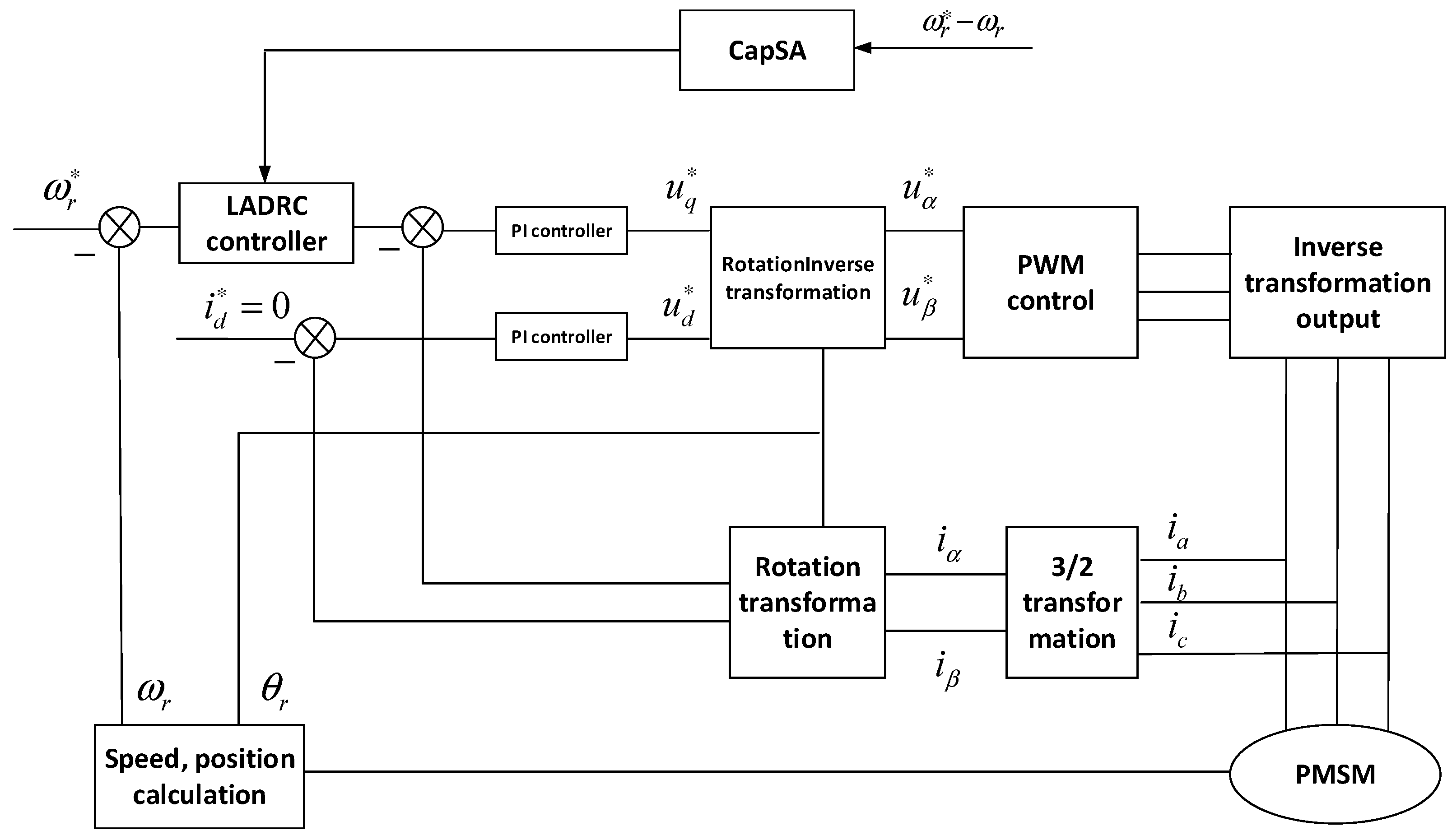
A PMSM control system simulation model based on CapSA-LADRC was developed on the MATLAB/Simulink platform to verify the speed regulation performance of this control method. The CapSA code was partially developed using MATLAB [22]. Experimental studies under identical simulation conditions were conducted, with the specific control system architecture detailed in Figure 10 below.
The PMSM parameters and operating conditions used in the simulation experiment are as follows Table 1.

5.1.1. Convergence Verification

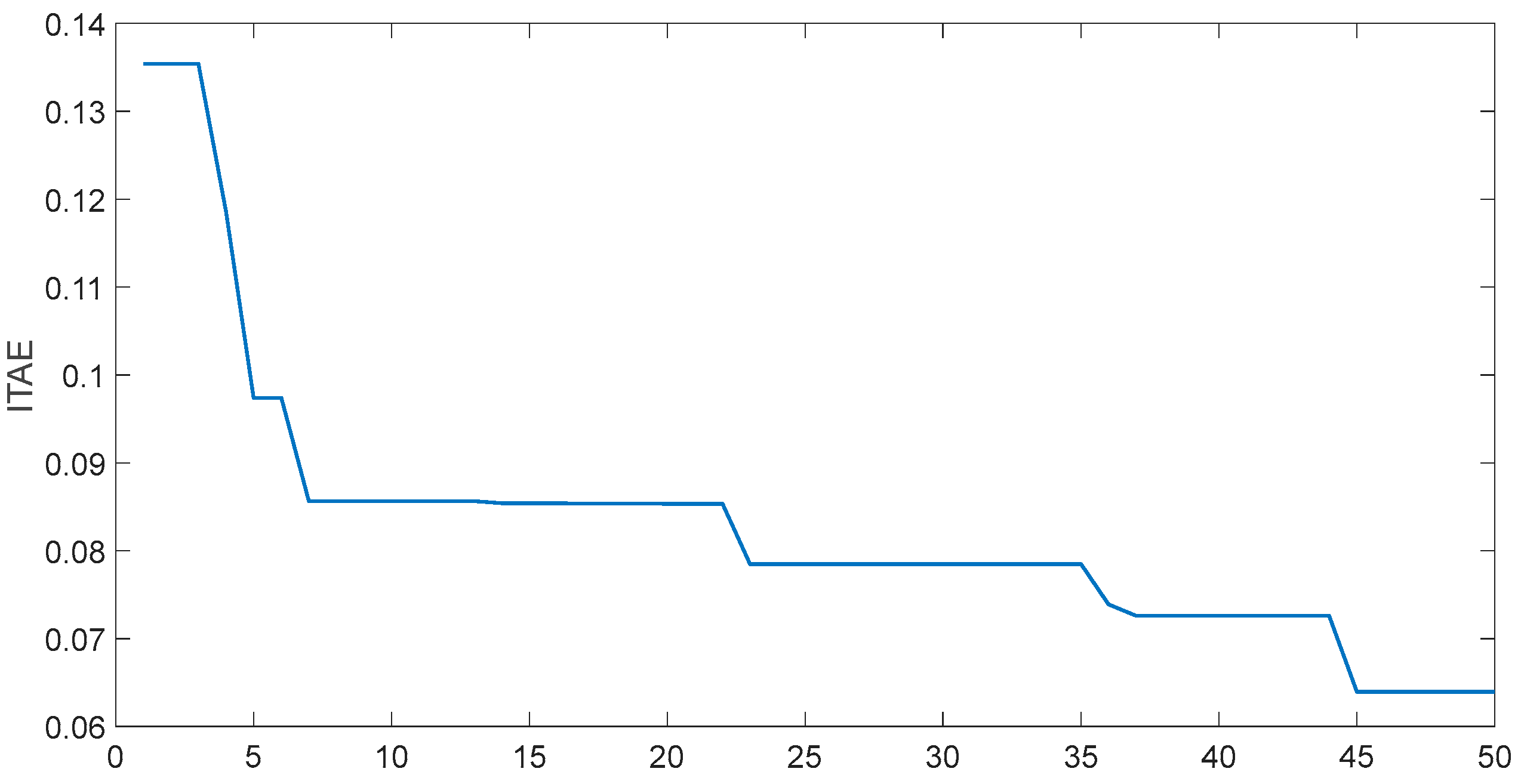
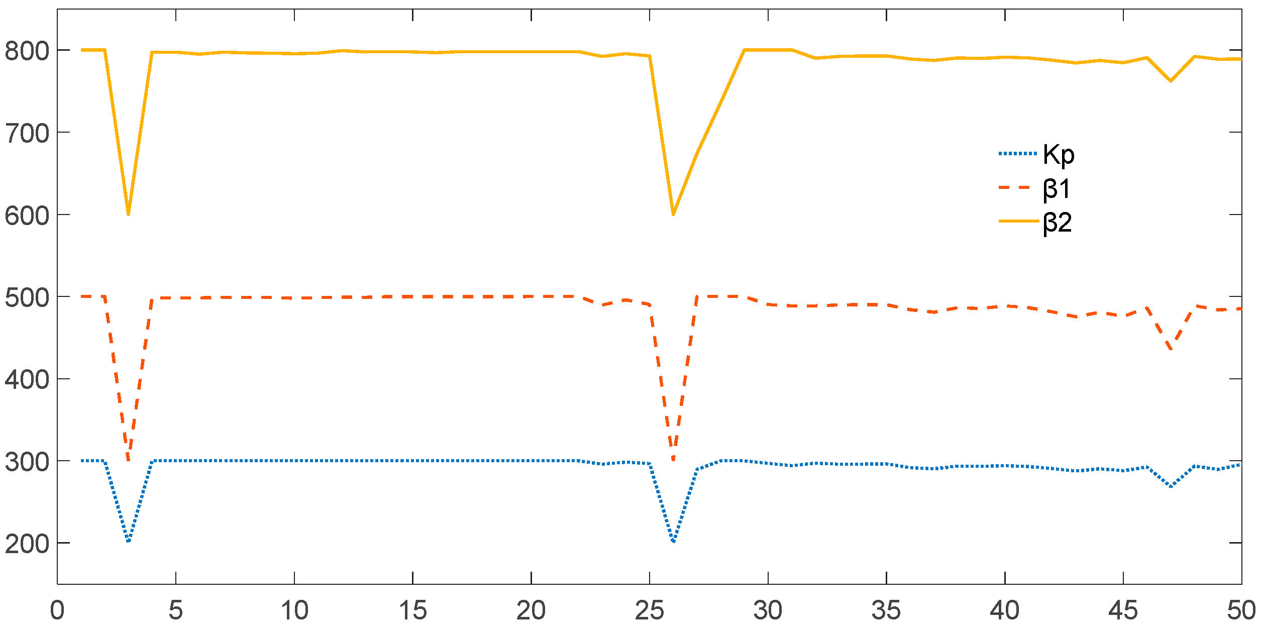
The speed reference is set to 1000 r/min, and a disturbance of 3 N·m is applied at 0.15 s. The parameters of the controller are iteratively optimized and selected by the CapSA algorithm. The optimization curve of the control performance index ITAE and the parameter optimization variation curves of β1, β2, and Kp are shown in Figure 11 and Figure 12, respectively. From Figure 11 and Figure 12, it can be observed that during the optimization of LADRC parameters by the CapSA algorithm, the ITAE index continuously decreases with the number of iterations, indicating an improvement in control performance. The values of β1, β2, and Kp gradually stabilize as the number of iterations increases. After 50 iterations, the ITAE index converges to an optimal value of 0.0640, and the values of β1, β2, and Kp no longer change, yielding the final optimized results for β1, β2, and Kp.

5.1.2. Validity Validation

In order to verify the effectiveness of the CapSA-LADRC control PMSM system, the simulation results of the PI control system, LADRC control system and CapSA-LADRC control system are compared under different working conditions.
(1)
Start with no load and increase the load
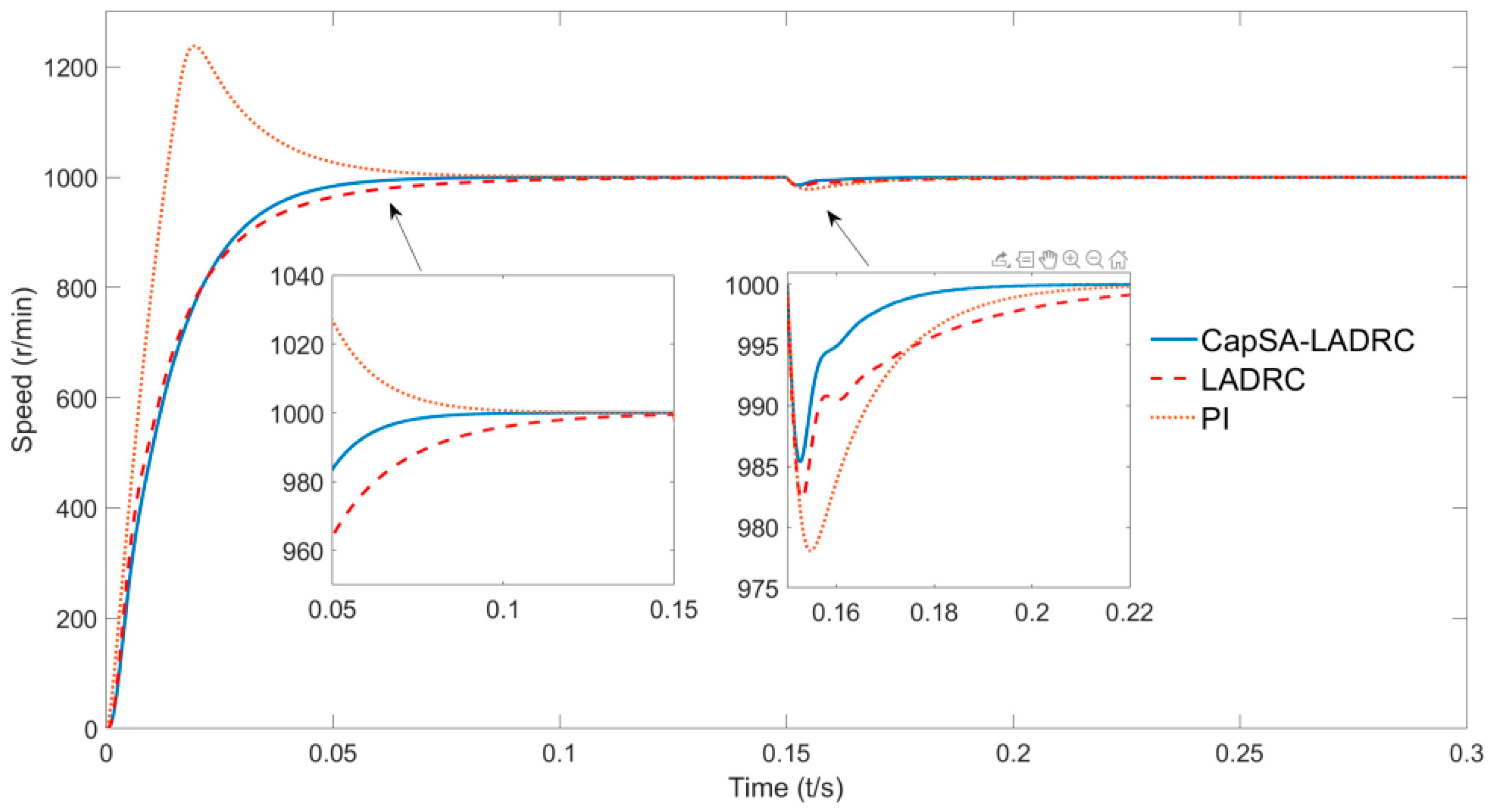
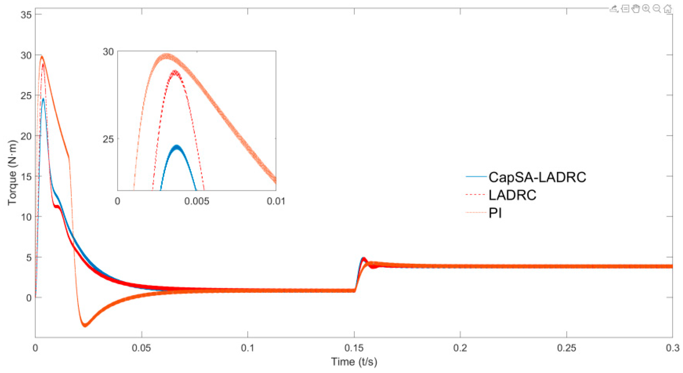
The motor is running in no-load mode, given as 1000 r/min. A constant load of 3 N·m is applied to the motor at 0.15 s. The same comparison of PI, LADRC and CapSA-LADRC speed and rectangular waveform is shown in Figure 13 and Figure 14.
As shown in Figure 13, prior to 0–0.05 s, the PI controller first reached its rated speed of 1000 r/min but exhibited significant overshoot. The stabilization time was longer than that of LADRC, which smoothly ascended to the set speed with reduced overshoot and maintained a stable state without oscillation. When disturbed at 0.15 s, the CapSA-LADRC system showed minimal speed drop and recovered to a rated speed by 0.17 s, whereas both the PI and LADRC systems took 0.2 s to reach their rated speeds (see Table 2). Figure 14 reveals that the CapSA-LADRC system demonstrates smaller peak torque values.
(2)
Load startup and load removal process
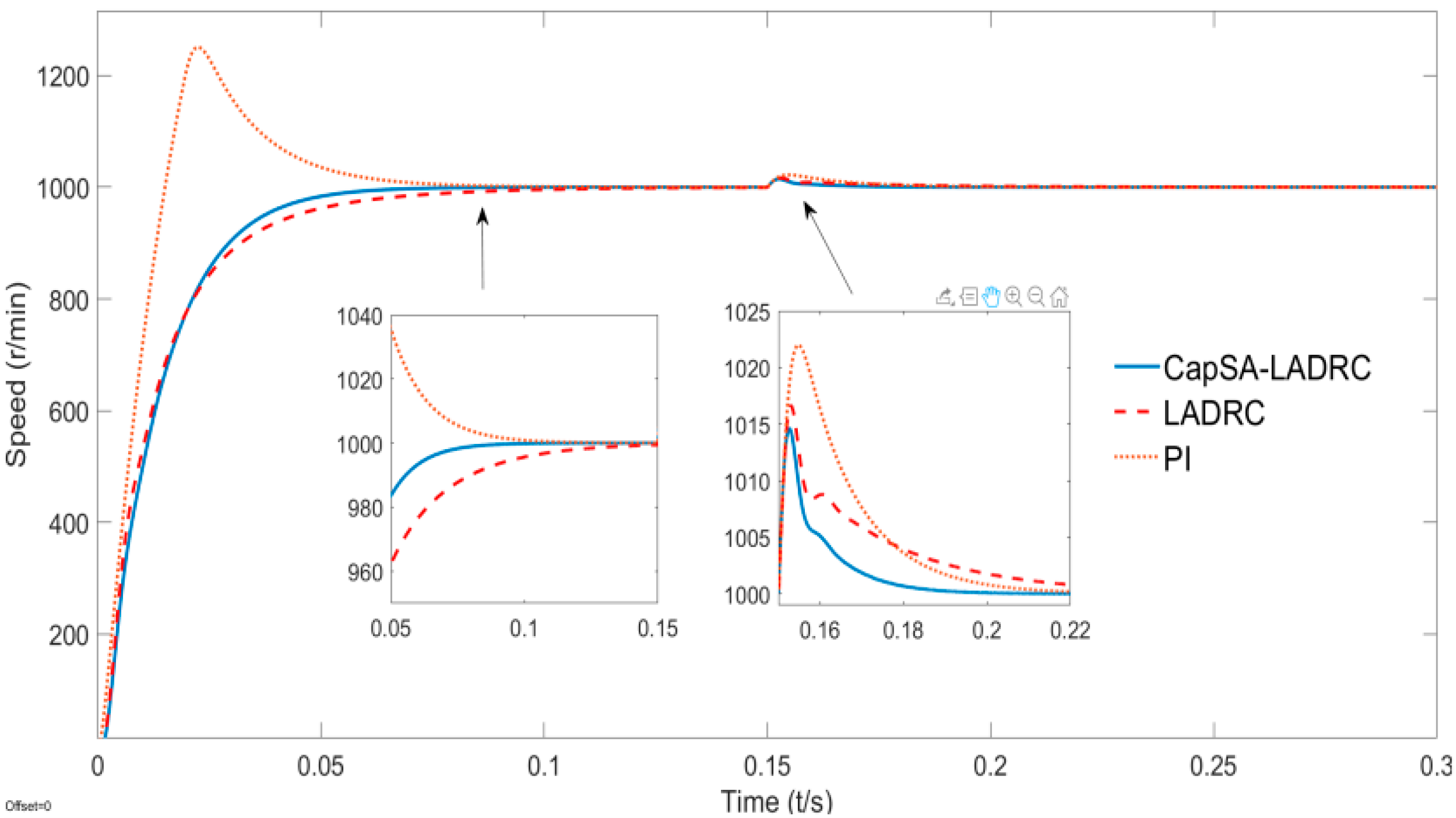
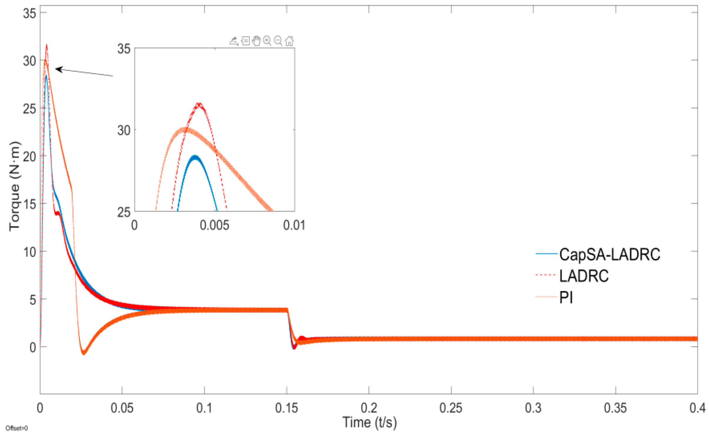
When starting with a 3 N·m load and removing the load in 0.15 s, the speed and torque waveforms of PI, LADRC and CapSA-LADRC are shown in Figure 15 and Figure 16.
Through three controllers (PI, LADRC, and CapSA-LADRC), we compared the rotational speed and torque performance of the simulation system under different conditions. When the motor was disturbed after achieving stable operation, the CapSA-LADRC demonstrated superior effectiveness compared to PI and LADRCs. Specifically, it exhibited a shorter time to recover to steady state, smaller speed variations caused by disturbances, and stronger disturbance resistance capabilities, making CapSA-LADRC outperform PI and LADRCs in these aspects as summarized in Table 3.

5.2. Simulation Results of the Multi-Motor Coordination Control System

Control Structure Simulation of Multi-Motor Coordination Control System

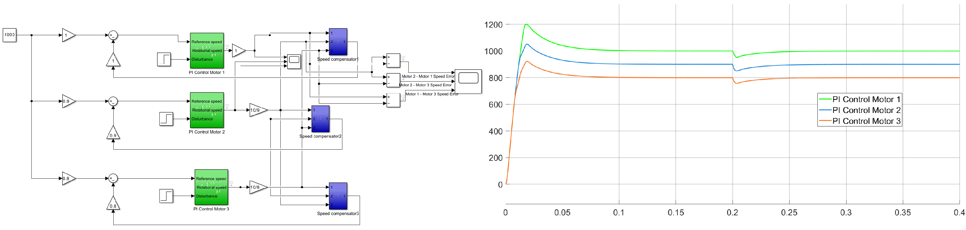
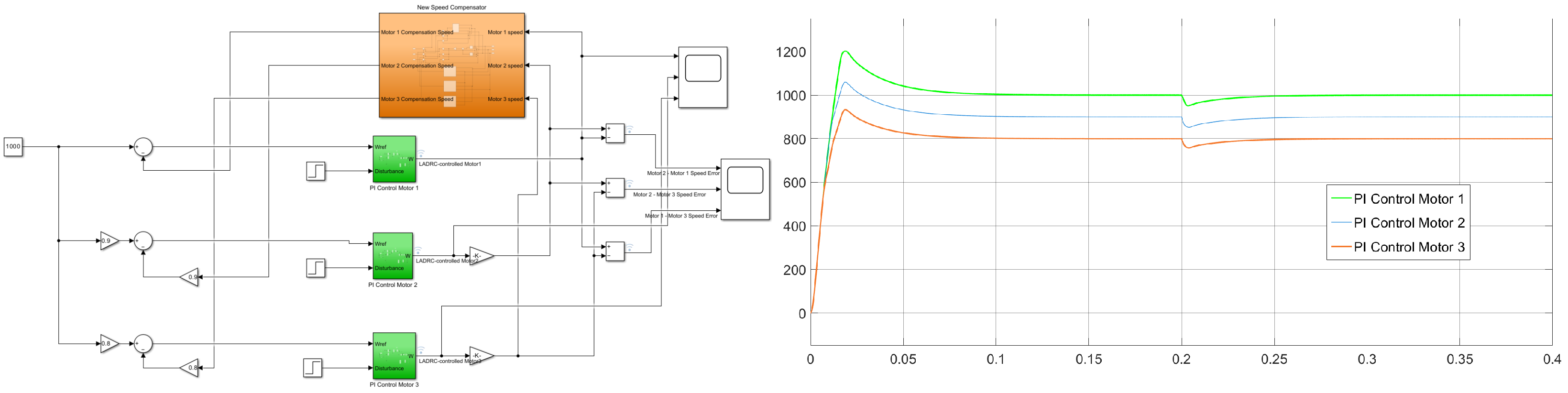
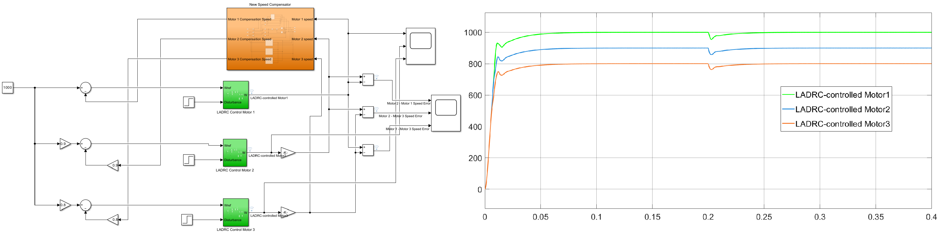
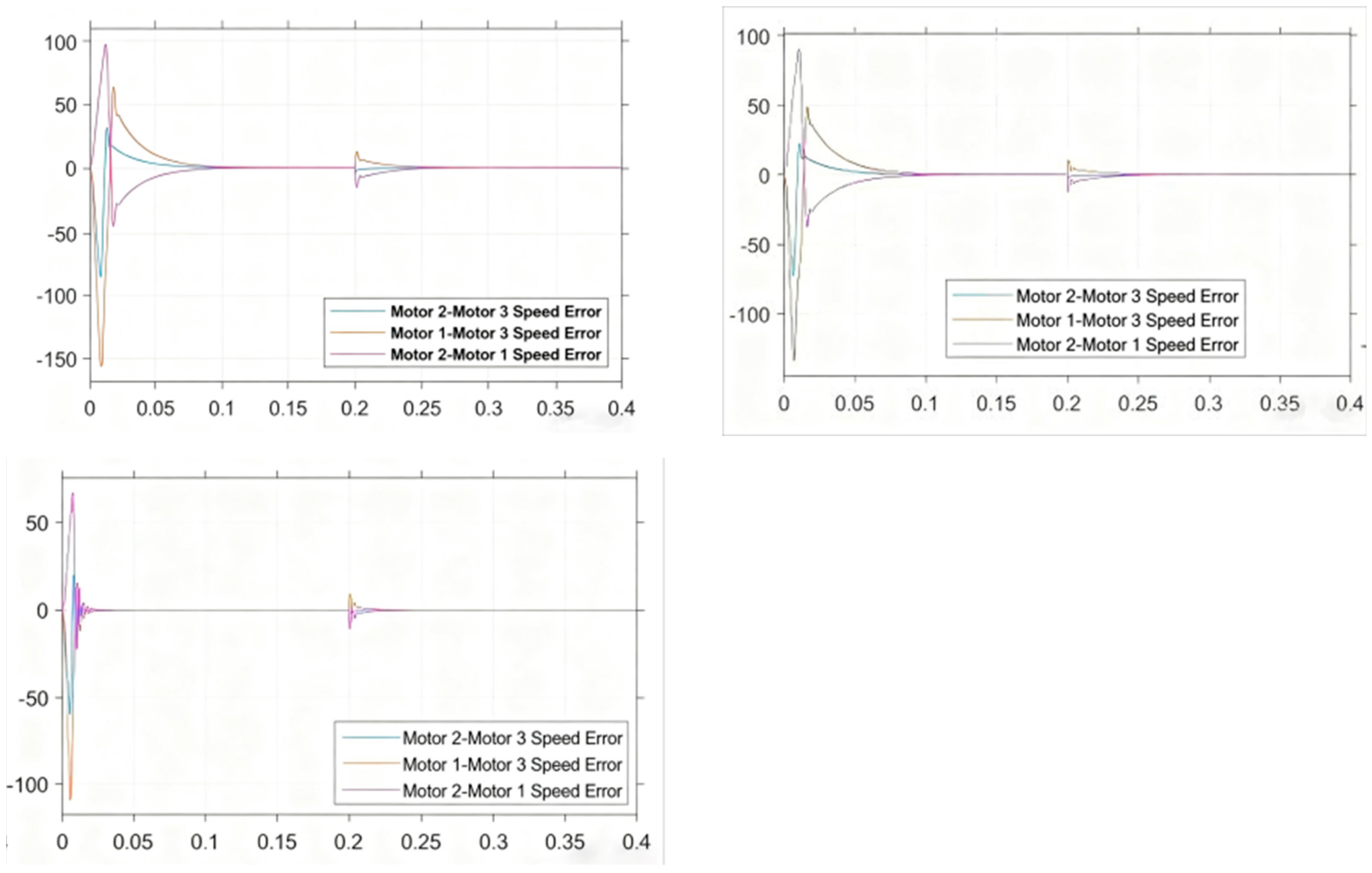
This paper investigates several common multi-motor coordination control architectures, conducting comparative analyses from multiple perspectives. Conventional parallel control, master-slave control, and cross-coupling methods prove unsuitable for wire drawing machines, while deviation coupling demonstrates superior adaptability to their operational requirements. To validate the feasibility and performance of both deviation coupling and its enhanced variant, a multi-motor control simulation model for wire drawing machines was developed in MATLAB. Using three motors as case studies, the model implements both deviation coupling and its optimized variant architectures. The controllers employ PI controllers and linear self-reducing controllers, respectively, for simulation comparisons. The simulation model diagrams and results are presented in the following Figure 17, Figure 18 and Figure 19.
The parameters of each motor are set according to Table 4. The system’s reference speed is set to 1000 r/min, and the simulation time is set to 0.4 s. At 0.2 s, sudden disturbance loads of 5 N·m are applied to Motor No. 1, 10 N·m to Motor No. 2, and 8 N·m to Motor No. 3, simulating load disturbances during the wire drawing machine’s operation. The green part of the following three simulation models is the PMSM model, and the rest of the color parts are the speed compensator.
In the simulation diagrams from Figure 17 to Figure 18, PI-controlled Motor 1 represents the simulation curve of the first motor under PI control, and the same applies to 2 and 3. LADRC-controlled Motor 1 represents the simulation curve of the first motor under LADRC control, and the same applies to 2 and 3. The synchronization performance among the motors is further illustrated in Figure 20. Simulation experiments demonstrate that the improved deviation-coupled control structure with a linear self-controlling disturbance rejection controller achieves minimal speed fluctuations and rapid recovery under multi-motor load disturbances (see Table 5). The system enables nearly zero overshoot startup and low-jerk stable operation, supporting high-precision proportional coordination of multiple motors. This configuration meets the engineering requirements for speed stability and coordination in multi-pass drawing machines, effectively reducing risks of wire accumulation and breakage. The proposed approach demonstrates significant practical value in industrial applications.

6. Conclusions

This study investigates three permanent magnet synchronous motors and designs a novel deviation-coupled synchronous speed compensator. To further enhance the synchronization performance and anti-interference capabilities across multiple motors, a linear self-disturbance rejection controller is implemented in the PMSM speed loop, supplemented by the CapSA algorithm for parameter optimization. Building on this foundation, a synchronization control strategy for multi-pass straight-feeding wire drawing machine systems based on CapSA-LADRC is proposed. A three-pole PMSM speed synchronization system simulation model was established in MATLAB for comparative verification. The simulation results reveal the following conclusions:
(1)
The deviation coupling control strategy under the control of CapSA-LADRC achieves smooth operation with high speed and high torque, and the motor has faster response speed, smaller overshoot, stronger anti-disturbance capability, better dynamic responsiveness, and improved ability to follow the reference speed of the motor.
(2)
The new deviation coupling control structure greatly improves the stability and speed of the speed compensator by adding the error factor to it. Through simulation software, the system is verified, and it is found that each motor can quickly follow the given speed and that the static and dynamic performance of the system are good, which proves the feasibility and correctness of this control structure.
In conclusion, the above scheme improves the control performance between each motor and improves the precision and efficiency of metal products. In follow-up research work, we will further build a practical experimental platform, carry out physical experiments and engineering application verification, and improve the performance testing of the method in real scenarios.

Author Contributions

Y.C. and P.Q. were responsible for the study’s conceptualization. C.L. and Y.C. contributed to methodological development. The software implementation was handled by Y.C. and P.Q., while Y.C. and P.Q. performed validation. Y.C. conducted formal analysis, and the investigation was carried out by Y.C. and P.Q. Resources were provided by Y.C. and P.Q.; data curation was managed by Y.C. and P.Q. The original draft was prepared by Y.C., and C.L. contributed to reviewing and editing. P.Q. prepared the visualizations. Y.C. provided supervision, and C.L. handled project administration. Funding was acquired by C.L. All authors have read and agreed to the published version of the manuscript.

Funding

This project was funded by the Jilin Provincial Department of Education Research Project led by Ms. Qu Pingping, ‘Key Technologies of Photovoltaic Power Generation Systems and Grid-connected Inverter Control Strategy Based on Maximum Power Point Tracking’ (Project No.: JJKH20240083KJ) and the Jilin Provincial Development and Reform Commission Project ‘Monitoring and Early Warning of High-Power Rectifier Devices and Energy Efficiency Evaluation System’ (Project No.: 2022C045-11).

Data Availability Statement

The data are included in this manuscript.

Conflicts of Interest

The authors declare no conflicts of interest.

References

  1. Hu, J. Research on Control Strategies for Permanent Magnet Synchronous Motors Based on BP Neural Network. Master’s Thesis, Nanchang University, Nanchang, China, 2021. Available online: https://kns.cnki.net/kcms2/article/abstract?v=zO3wb1M9ekzKQ9a7_WLmUntEtDbt0VVxJHJAXDIoOgvcOz_h1PJRkQbKs4HTeLpS1YJVwW0jn_EPv_8p7zF3DpKJhYMBNiDO1hmL6eSXtarUdWfWgJioYly5A-SNbQgbCJGwJVbrXgWGhuHqHWDNoYAU5mJ-oZ3NDRlyl4gKsUA-k99O5YafYU8ZwBe1bhJb&uniplatform=NZKPT&language=CHS (accessed on 5 October 2025). (In Chinese)
  2. Wu, W.; Zhang, Y.; Ma, Z. A Model Predictive Speed Control for Permanent Magnet Synchronous Motors. Comb. Mach. Tools Autom. Process. Technol. 2023, 112–115. [Google Scholar] [CrossRef]
  3. Yu, B.; Peng, X.; Sheng, M.; Shen, A.; Luo, X. A Position-Sensitive Idle Start Strategy for SPMSM Based on Adaptive PWM Extension. J. Mot. Control 2023, 27, 1–10. (In Chinese) [Google Scholar] [CrossRef]
  4. Gao, Z. Scaling and bandwidth parameterization based controller tuning. In Proceedings of the 2003 American Control Conference; IEEE: Denver, CO, USA, 2003; pp. 4989–4996. Available online: https://www.researchgate.net/profile/Zhiqiang-Gao-13/publication/4039112_Scaling_and_Parameterization_Based_Controller_Tuning/links/00b7d520c0a5625121000000/Scaling-and-Parameterization-Based-Controller-Tuning.pdf (accessed on 18 March 2026).
  5. Zhu, L.; Zhang, G.; Jing, R.; Bi, G.; Xiang, R.; Wang, G. Nonlinear active disturbance rejection control strategy for permanent magnet synchronous motor drives. IEEE Trans. Energy Convers. 2022, 37, 2119–2129. [Google Scholar] [CrossRef]
  6. Fang, S.; Fan, J. A Composite Control Strategy for Permanent Magnet Synchronous Motors Based on Self-Adaptive Disturbance Rejection. J. Mot. Control. Appl. 2023, 50, 62–69. [Google Scholar] [CrossRef]
  7. Han, J. From PID to active disturbance rejection control. IEEE Trans. Ind. Electron. 2009, 56, 900–906. [Google Scholar] [CrossRef]
  8. Ding, W.; Du, Q.; Song, C.; Ling, H.; Luo, Y. Mean-coupled multi-motor sliding mode speed synchronous control. J. Xi’an Jiaotong Univ. 2022, 56, 159–170. (In Chinese) [Google Scholar]
  9. Ye, Y.; Peng, F.; Huang, Y. Comprehensive Review of Multi-Motor Synchronous Motion Control Technology. J. Electr. Eng. 2021, 36, 2922–2935. (In Chinese) [Google Scholar] [CrossRef]
  10. Zhu, B.; Zhang, Y.; Xu, P.; Song, S.; Jiao, S.; Zheng, X. A Dual-Motor Cross-Coupling Control Strategy for Position Synchronization. J. Harbin Univ. Sci. Technol. 2022, 27, 114–121. (In Chinese) [Google Scholar]
  11. Zhang, H.; Wang, Y.Y.; Zhang, G.W.; Tang, C.H. Research on LADRC strategy of PMSM for road-sensing simulation based on differential evolution algorithm. J. Power Electron. 2020, 20, 958–970. [Google Scholar] [CrossRef]
  12. Wen, D.; Wang, W.; Zhang, Y. Sensorless Control of Permanent Magnet Synchronous Motor in Full Speed Range. Chin. J. Electr. Eng. 2022, 8, 97–107. [Google Scholar] [CrossRef]
  13. Wang, Z.; Zhang, H. PI Control Strategy for Electric Vehicle Permanent Magnet Synchronous Motors Based on SVPWM. Intern. Combust. Engine Accessories 2020, 25–30. (In Chinese) [Google Scholar] [CrossRef]
  14. Zou, Y.; Bu, R.; Li, Z. Consideration of lateral drift in ship path tracking with self-disturbance rejection control. J. Ship Eng. 2020, 40, 101–104. (In Chinese) [Google Scholar]
  15. Wei, X.; Tang, T.; Deng, Y. Research on Speed Control of Linearly Self-Adaptive Permanent Magnet Synchronous Motor. Mech. Manuf. 2021, 50, 44–48. [Google Scholar]
  16. Jilak, A.; Assareh, E.; Nedaei, M. Application of a novel multi-objective optimisation method integrated with the artificial neural networks for optimum design of a plate heat exchanger. Aust. J. Mech. Eng. 2020, 18, 1–15. [Google Scholar] [CrossRef]
  17. Braik, M.; Sheta, A.; Al-Hiary, H. A novel meta-heuristic search algorithm for solving optimization problems: Capuchin search algorithm. Neural Comput. Appl. 2021, 33, 2515–2547. [Google Scholar] [CrossRef]
  18. Shao, J.; Jiang, Q.; Ni, Y.; Zhou, T.; Li, Z. Position control strategy for permanent magnet synchronous motor based on improved self-disturbance rejection control. Control. Eng. 2022, 29, 1487–1496. (In Chinese) [Google Scholar]
  19. Wang, Y.; Cao, K. Overview of the Development of Multi-Motor Synchronous Control Technology. Micro Spec. Mot. 2019, 47, 69–73. [Google Scholar]
  20. Shi, S.; Wang, G.; Cao, Y.; Wang, Z. Review of multi-axis collaborative control technology of servo system. Trans. CSEE 2025, 45, 4479–4493. [Google Scholar]
  21. Han, R.; Guo, Y.; Zhu, L.; He, Q. Overview of Multi-Motor Synchronous Control. Mot. Control. Appl. 2017, 44, 8–12. (In Chinese) [Google Scholar]
  22. Chen, H.; Fan, Y.; Jiang, L.; Fang, Z.; Ge, X. Development of an Automatic Control Visualization Simulation Platform Based on MATLAB. J. Tonghua Norm. Univ. 2021, 42, 95–100. (In Chinese) [Google Scholar]
Figure 1. Working flow chart of straight drawing machine.
Energies 19 01798 g001
Figure 2. Schematic diagram of working principle of multi-pass straight drawing machine.
Energies 19 01798 g002
Figure 3. Schematic diagram of multi-pass straight drawing machine.
Energies 19 01798 g003
Figure 4. Vector control structure of permanent magnet synchronous motor.
Energies 19 01798 g004
Figure 5. Structure of first-order linear self-disturbance rejection controller.
Energies 19 01798 g005
Figure 6. Structure of first-order linear self-disturbance suppression for speed loop controller of permanent magnet synchronous motor.
Energies 19 01798 g006
Figure 7. CapSA algorithm process.
Energies 19 01798 g007
Figure 8. Synchronous error compensator.
Energies 19 01798 g008
Figure 9. Schematic diagram of improved deviation coupling speed compensator structure.
Energies 19 01798 g009
Figure 10. Permanent magnet synchronous motor control system based on CapSA-LADRC.
Energies 19 01798 g010
Figure 11. ITAE optimization curve.
Energies 19 01798 g011
Figure 12. Parameter optimization variation curve.
Energies 19 01798 g012
Figure 13. Comparison of Speed between PI, LADRC and CapSA-LADRC during load mutation.
Energies 19 01798 g013
Figure 14. Comparison of torque between PI, LADRC and CapSA-LADRC during load mutation.
Energies 19 01798 g014
Figure 15. Comparison of PI, LADRC and CapSA-LADRC speeds during load start and load removal process.
Energies 19 01798 g015
Figure 16. Comparison of PI, LADRC and CapSA-LADRC torques during load start and load removal process.
Energies 19 01798 g016
Figure 17. Structure system and actual speed output of three-stage drawing machine with deviation coupling control.
Energies 19 01798 g017
Figure 18. Structure system and actual speed output of three-stage drawing machine with improved deviation coupling control.
Energies 19 01798 g018
Figure 19. Three-stage drawing machine structure system with improved deviation coupling and linear self-disturbance control of driving unit and actual speed output.
Energies 19 01798 g019
Figure 20. Simulation diagram of synchronous speed error comparison between driving units of three-stage straight advancing drawing machine.
Energies 19 01798 g020
Table 1. Parameters of permanent magnet synchronous motor.
ParameterNumeric Value
D C   r e a c t a n c e   L d / H 0.00525
m o m e n t   o f   i n e r t i a   J / Kg · m 2 0.003
P e r m a n e n t   m a g n e t   f l u x   ψ f / Wb 0.04 + j0.0004
r a t e d   v o l t a g e   U N / V 0.024 + j0.0003
A C   R e a c t a n c e   L d / H 0.00525
c a m p i n g   c o e f f i c i e n t   B / ( N · S / m ) 0.008
number of pole-pairs4
R e s i s t o r s   R / Ω 0.958
Table 2. Simulation analysis comparison under no-load conditions.
Control MethodOvershootRising Time/sAdjust the Time/sPerturbation Recovery Time/sSteady-State Error
PI24.7%0.0250.030.0652.2%
LADRC0%0.0200.081.75%
CapSA-LADRC0%0.05500.031.5%
Table 3. Simulation analysis comparison under load.
Control MethodOvershootRising Time/sAdjust the Time/sPerturbation Recovery Time/sSteady-State Error
PI24.7%0.0250.0330.0652.2%
LADRC0%0.01500.081.75%
CapSA-LADRC0%0.05800.031.5%
Table 4. Multi-motor parameters.
Electric MotorMotor 1Motor 2Motor 3
power rating (W)100015002000
rated voltage (V)220220220
rated torque (N·m)71013
rated speed (r/min) 100010001000
Rs (Ω)0.9580.9580.958
L q = L d ( m H ) 121212
permanent magnet flux ( ψ f / W b )0.18270.18270.1827
camping coefficient B   ( N S / m ) 0.0080.0080.009
moment of inertia J k g m 2 0.0030.0030.003
Table 5. Coordination control performance index of three-step straight drawing machine.
ErrorDeviation CouplingImproved Bias CouplingImproved Deviation Coupling and LADRC Control Motor
ζ q 23 9.5%8.1%5.4%
ζ r 23 0.5%0.3%0.16%
ζ q 13 15.7%13.4%10.9%
ζ r 13 1.3%1%0.8%
ζ q 21 11%10.5%7.3%
ζ r 21 1.8%1.4%1.1%
Disclaimer/Publisher’s Note: The statements, opinions and data contained in all publications are solely those of the individual author(s) and contributor(s) and not of MDPI and/or the editor(s). MDPI and/or the editor(s) disclaim responsibility for any injury to people or property resulting from any ideas, methods, instructions or products referred to in the content.