1. Introduction
With the widespread use of fossil fuels, global warming caused by carbon emissions has become an increasingly severe problem. The weight of renewable energy sources such as solar, wind, and hydrogen energy is growing significantly. Since 2023, the application of renewable energy has seen substantial growth, with photovoltaic and wind power experiencing particularly rapid development [
1]. Renewable energy systems offer economic advantages such as widespread resource distribution, freedom from geographical constraints, and on-demand installation. Compared to traditional power plants with lengthy construction cycles, this decentralized power generation model proves more flexible and efficient [
2]. However, distributed renewable energy also poses significant technical challenges to microgrid systems. First, the output of distributed power sources such as photovoltaics exhibits pronounced intermittency and volatility, with power generation directly influenced by weather conditions, leading to frequent fluctuations on minute-to-second timescales. Second, coordinating multiple distributed power sources is complex; without effective energy management, issues like power backflow and circulating currents can easily arise, threatening the system’s safe and stable operation. To address these issues and enhance the reliability and stability of renewable energy integration, it is necessary to deploy energy storage systems (ESS) with both high power and large capacity characteristics within the power system. These ESS dynamically absorb excess energy or compensate for power deficits [
3,
4]. This mitigates load fluctuations and enables efficient management of the grid’s demand side, thereby performing peak shaving and valley filling. Ultimately, it ensures a high-quality, safe, and reliable power supply while meeting the demand for efficient electricity consumption [
5,
6,
7].
Currently, no single energy storage device can simultaneously offer high capacity and rapid response capabilities. To provide a clearer technical perspective on these limitations,
Table 1 summarizes the performance characteristics of mainstream energy storage. As shown in the table, although pumped storage and compressed air energy storage offer large capacities, they exhibit slow response times and are constrained by geographical conditions; battery storage, while widely applied, has a limited lifespan. Therefore, developing hybrid energy storage systems (HESS) is an inevitable choice for enhancing the operational stability of microgrid systems.
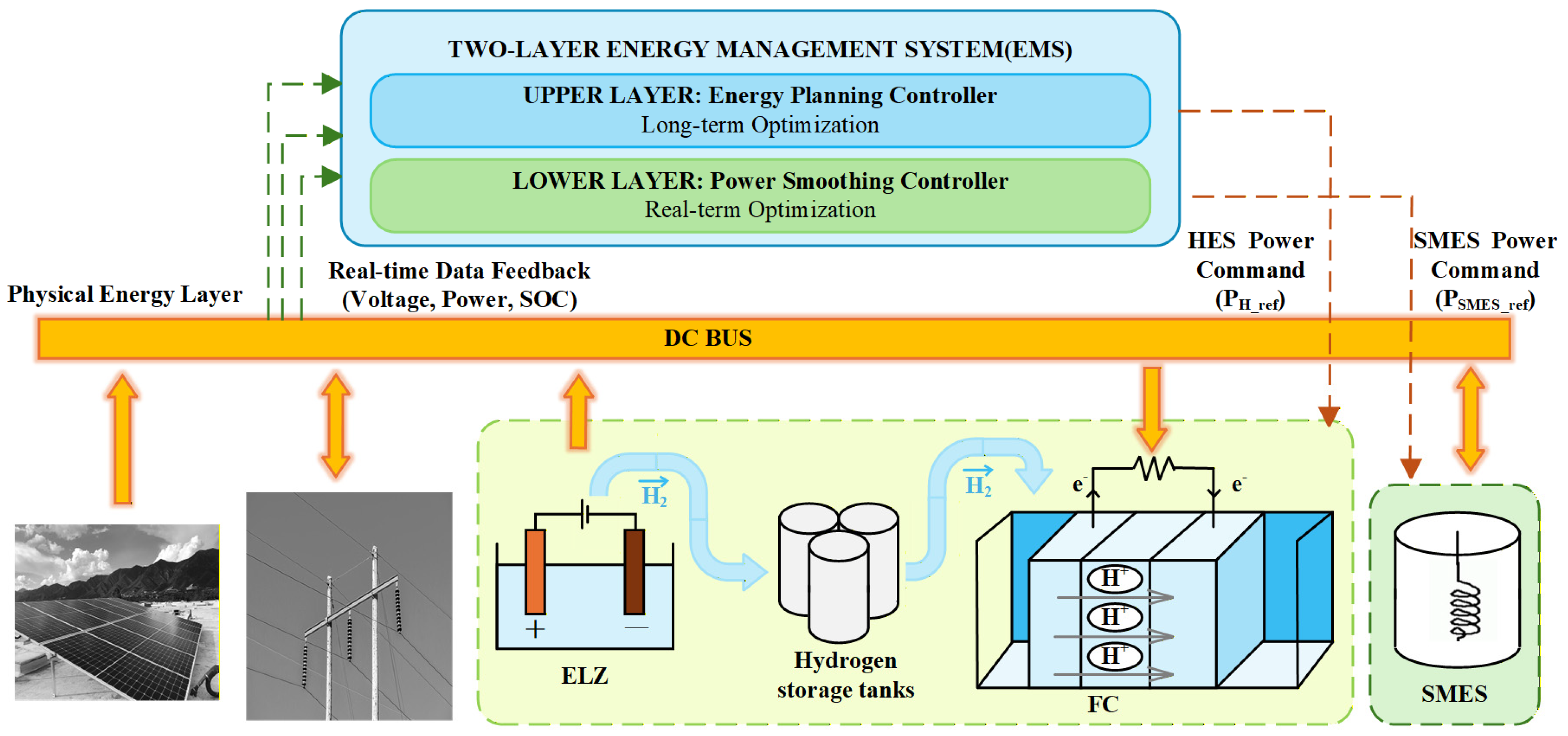
Hydrogen energy storage (HES), comprising electrolyzers (ELZ), hydrogen tanks, and fuel cells (FC), is selected as the energy-intensive component due to its high energy density and capability for long-term, cross-seasonal storage [
9]. Hydrogen energy is widely regarded as a key technology for achieving deep decarbonization. Global hydrogen demand continues to grow, showing significant expansion despite falling short of projections [
10], further highlighting the technological foresight of integrating HES. HES enables bidirectional electricity-to-hydrogen conversion via ELZ and FC. ELZ produces “green hydrogen” through water electrolysis, effectively absorbing surplus electricity from renewable sources. FC convert hydrogen back into electricity, providing flexible power support for the system [
11]. However, HES relies on complex electrochemical and thermodynamic processes, resulting in a slow dynamic response and difficulty mitigating high-frequency fluctuations from photovoltaic systems.
To address this limitation, superconducting magnetic energy storage (SMES) is introduced as the complementary power-intensive unit. Compared to conventional batteries or supercapacitors, SMES offers exceptional characteristics: millisecond-level response speed, high power density, and extended cycle life. It provides the system with rapid frequency response and stability support [
12,
13]. This technology is now applied in renewable energy generation with significant power fluctuations [
14]. As shown in
Table 1, from a techno-economic perspective, although SMES exhibits relatively higher initial investment costs per unit energy, its superior cycle efficiency and significantly lower annual operational and maintenance expenses confer greater economic advantages over supercapacitors in handling high-frequency power fluctuations. Furthermore, SMES experiences no chemical degradation over millions of cycles, ensuring long-term stable operation within the dual-layer MPC framework proposed herein and thereby reducing the system’s total lifecycle costs. Integrating SMES with HES creates a complementary structure: SMES absorbs transient power surges while HES addresses sustained energy demands. This coordinated fast–slow mechanism effectively resolves the inherent multi-timescale disturbance challenges in renewable energy systems.
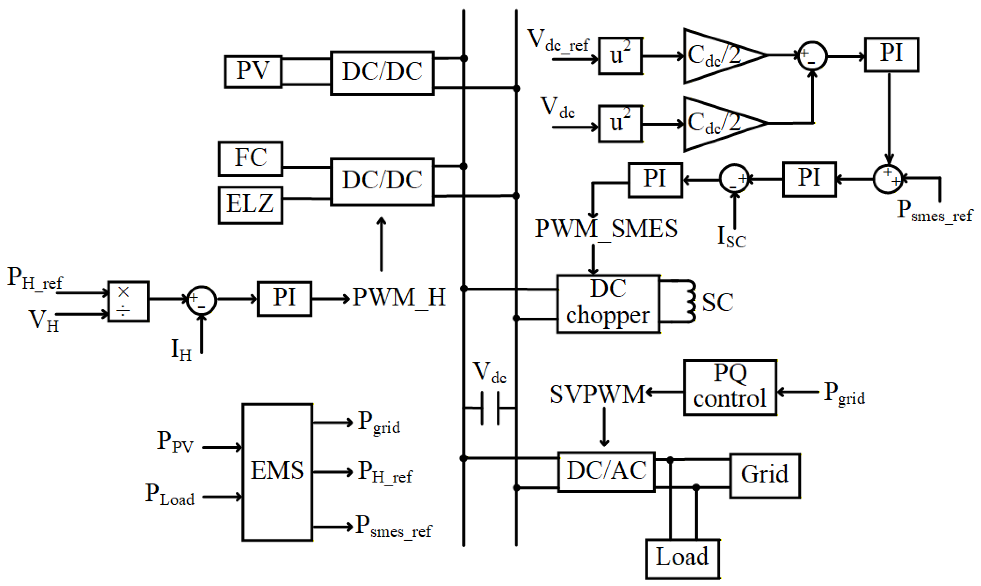
HESS, composed of SMES and HES, enables rapid power compensation and fault ride-through during continuous grid faults and high-power disturbances, thereby safeguarding the secure and stable operation of power systems. To fully leverage the integrated capabilities of HESS, the energy management system (EMS) must dynamically formulate charging/discharging schedules and power allocation strategies for energy storage units based on global optimization objectives, further enhancing the stability and economic efficiency of microgrid operation [
15]. Particularly due to the significant temporal scale differences between SMES and HES, traditional single-layer optimization frameworks struggle to coordinate these multi-timescale dynamic characteristics. They often sacrifice system dynamic response performance while achieving economic objectives, or vice versa. Consequently, the research community has increasingly turned its attention to two-layer optimization architectures. Ref. [
16] proposes a typical two-layer optimization structure, where the upper layer aims to minimize the total operational costs, while the lower layer focuses on minimizing the operating costs of the HES. Simulation results demonstrate that this structure significantly reduces overall costs. The system designed in [
17] effectively reduced fuel consumption, with its upper layer allocating power through fuzzy inference and its lower layer dedicated to minimizing operational losses. Nevertheless, most existing strategies rely on static optimization based on forecast data, which often overlooks the impact of frequent mode switching on HES lifespan and lacks the adaptability to handle the stochastic uncertainties of renewable energy.
Model predictive control (MPC) has become a cornerstone in microgrid management for its superior constraint handling and predictive optimization. It is particularly adept at multi-timescale power allocation [
18,
19]. For example, an adaptive control framework utilizing event-triggered tracking and switching functions to maintain stability under uncertain conditions [
20]. In more complex networked scenarios, ref. [
21] proposed a new distributed economic MPC (DEMPC) strategy for load frequency control with large-scale PEV participation. Additionally, ref. [
22] provided an alternative reinforcement learning-based energy management approach capable of handling high randomness without requiring precise system models.
Although adaptive control or learning methods offer superior robustness, their online parameter updates and iterative optimization increase computational complexity. Meanwhile, the extremely fast response speed of SMES demands control loops with minimal latency. To address this, this paper prioritizes a deterministic two-layer MPC framework over the aforementioned approaches. By decoupling timescales, this method achieves robust and efficient coordination between SMES and HES by utilizing MPC’s rolling optimization and feedback correction to compensate for model inaccuracies while maintaining computational efficiency.
As a result, the contributions of this research work are as follows:
I. An integrated model of SMES and HES was established, providing a foundation for system simulation and control strategy design.
II. A two-layer MPC framework was designed to address the multi-timescale dynamic characteristics of this system. The upper layer performs optimization scheduling targeting hydrogen production revenue and grid economic efficiency, while the lower layer utilizes the response capability of SMES to achieve power fluctuation smoothing and error compensation.
III. This work broke through the limitations of traditional battery/supercapacitor hybrid architectures by innovatively integrating HES with SMES. A two-layer EMS tailored for this system was proposed, significantly enhancing economic efficiency while ensuring overall system stability.
3. Proposed Two-Layer EMS
HES is suitable for hourly energy scheduling, while SMES is suitable for handling power fluctuations on a second-to-minute scale. Therefore, two-layer EMS optimization can be used to address issues across different time scales and fully leverage the complementary characteristics of hybrid energy storage. Since PV output is weather-dependent, MPC is employed to manage scheduling within specific timeframes. Through rolling optimization and feedback, it compensates for prediction uncertainty [
26]. While the dual-layer approach in [
27] primarily focuses on transforming long-term degradation costs into short-term operational targets for microgrid planning, the proposed framework prioritizes real-time power allocation and dynamic feedback correction across multiple timescales. Furthermore, by incorporating a mode-switching penalty, this strategy addresses the equipment lifetime degradation issues highlighted in [
28], enhancing system durability while handling complex constraints.
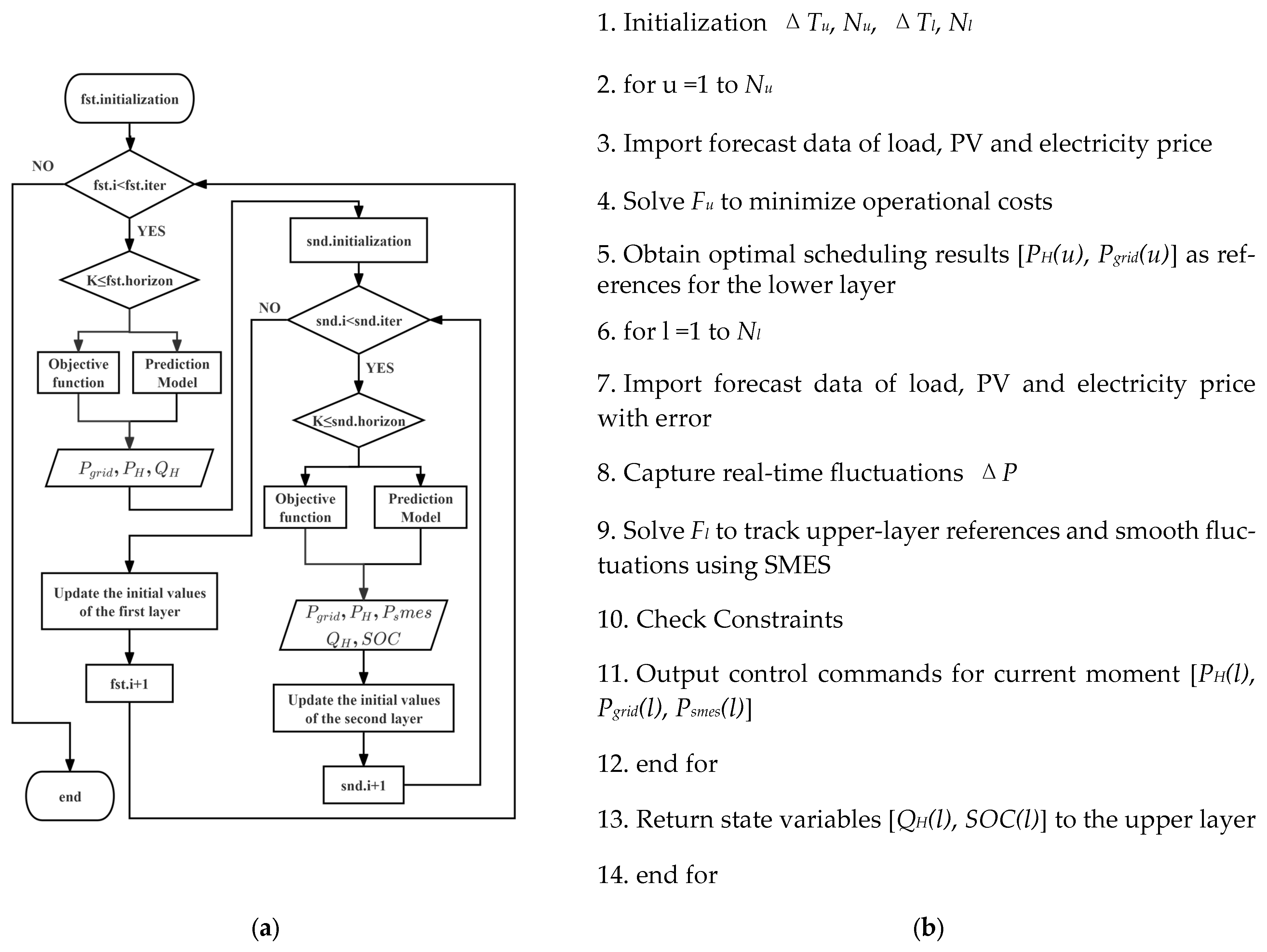
Figure 3 shows the flowchart and algorithm of the two-layer MPC energy management strategy proposed in this paper. First, initialize the state variables, input variables, prediction duration, and solution durations (number of iterations) for the upper and lower layers. At this point, the upper-layer controller enters the first iteration of optimization. Under the constraint conditions, use the prediction model (7) to perform rolling optimization and solve the optimization variables for the objective problem, obtaining the optimal solution reference value within the predicted duration. The solved value is used as the initial value for the second layer and repeat the same steps. At this point, the prediction model becomes (7) and (9), completing the second layer’s “snd. iter” iterations. This iterative procedure continues as the system returns to the first layer for the next optimization cycle.
3.1. Mathematical Model of Upper Layer EMS
The upper-level EMS optimization variables are grid power
Pgrid and HES system power
PH, which must satisfy the power constraint.
where the superscript
u denotes the upper-layer optimization variable, and
l denotes the lower layer. Further explanation will not be provided in the subsequent text.
Pgrid > 0 represents purchasing electricity from the grid, and vice versa for selling electricity. FC and ELZ both belong to HES, and they cannot operate simultaneously; their operating states are complementary. Therefore, if PH < 0, it indicates that ELZ is operating; if PH > 0, FC is operating and ELZ is not operating.
Due to the response delay characteristics of hydrogen fuel cells during startup and operation, it is necessary to limit their ramp rate.
Inequality constraints include
Pgrid,
PH, and hydrogen storage tank capacity
QH constraints.
The upper-level EMS optimization objective is to minimize operating costs, which include grid purchase/sale costs, net hydrogen production costs from ELZ, and FC costs.
The grid power exchange cost
Cgrid represents the expense of purchasing electricity from the main grid or the revenue from selling surplus power back to it, which can be expressed as:
where
p represents the electricity price.
Hydrogen production costs
CELZ can be expressed as:
where
m0 represents the unit costs of hydrogen production, and
m1 and
m2 represent the unit selling prices of hydrogen and oxygen, respectively.
FC costs
CFC include initial investment costs and operating and maintenance costs.
where CC represents the costs of PEMFC, COM represents operating and maintenance costs, and
t1 represents operating time.
Therefore, the upper-level optimization problem
Fu can be expressed as:
3.2. Mathematical Model of Lower Layer EMS
SMES has a relatively low capacity and serves to compensate for prediction errors and power fluctuations. Therefore, the power of SMES
Psmes is used as the third optimization variable for the lower-level EMS, and the power balance constraint becomes:
Ensure the safe operation of SMES and prevent overcharging and over-discharge by constraining it
Psmes and SOC.
When minimizing the deviation from the upper-level scheduling reference value in the lower-level optimization model, the uncertainty of short-term photovoltaic power forecasts is reflected in the deviation of the hydrogen storage system and grid power commands by introducing a quadratic penalty costs function
Cp. Based on the power reference value output by the upper-level decision layer, this penalty term can be expressed in the following mathematical form:
Since SMES installations have a long service life and do not require maintenance or replacement, the lower-level optimization objective does not consider SMES costs. The optimization function is expressed as:
By enabling HES and SMES to operate at the time scales and control levels best suited to their respective characteristics through this EMS, economic efficiency and robustness can be achieved simultaneously.
4. Simulation Results and Analysis
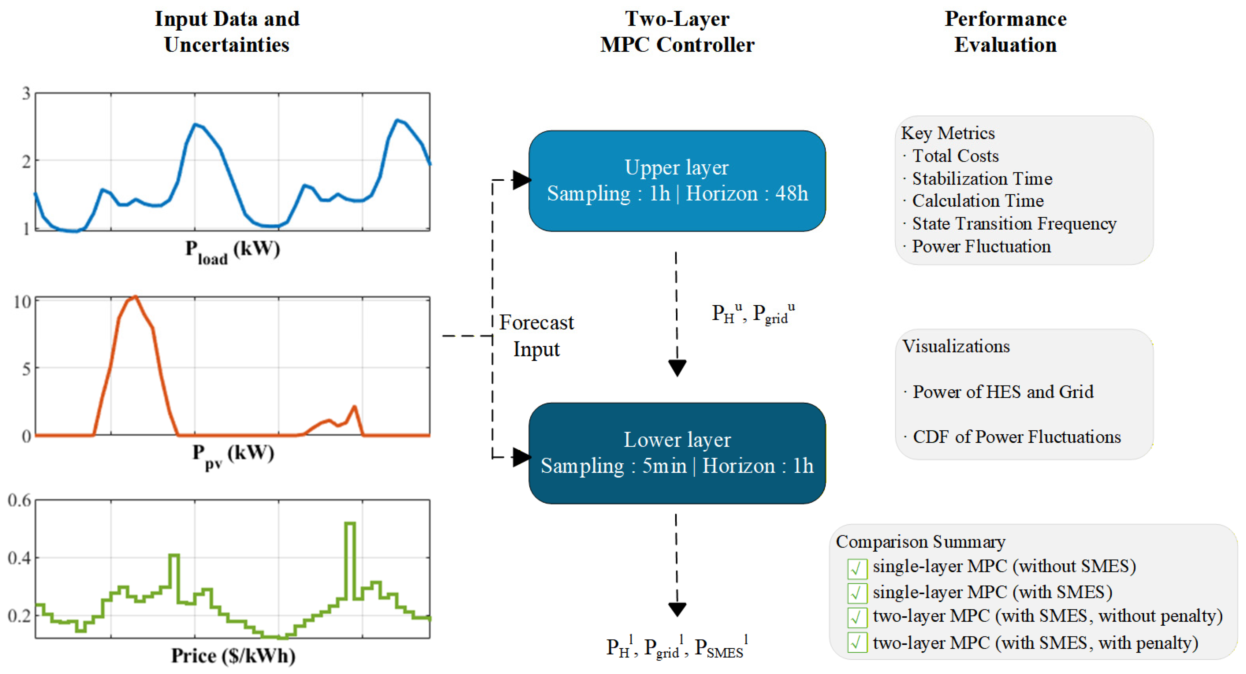
To evaluate the performance of the proposed two-layer MPC strategy, this section conducts a comprehensive simulation analysis based on a typical microgrid case. Additionally, to account for forecasting uncertainty, a ±5% prediction error margin was incorporated into the photovoltaic power used in the MPC. The overall validation framework, encompassing input data characteristics, controller configurations, performance metrics, and the four compared control strategies, is illustrated in
Figure 4.
In this study, we specifically consider a high-fluctuation renewable energy scenario to examine the robustness and economic efficiency of the system under extreme conditions. The simulation platform is built in MATLAB/Simulink 2023b, with detailed operational parameters, physical constraints, and sampling time scales for this case study summarized in
Table 2.
The optimization objective of the two-layer MPC proposed in this paper involves quadratic terms, which, together with linear constraints, form a convex QP problem. Due to the positive semidefiniteness of the Hessian matrix, this problem possesses a unique global optimal solution. The interior-point method is employed for its solution, ensuring extremely high computational efficiency and real-time feasibility.
The control architecture operates on dual time scales to decouple energy management from power smoothing. The upper layer utilizes forecasted load, PV generation, and real-time electricity price signals to generate global optimal power references and SOC trajectories. The lower layer tracks these references on a faster time scale. This hierarchical structure inherently ensures closed-loop stability. Furthermore, the convexity of each constraint and the iterative recalculation of each step guarantee recursive feasibility. The lower layer returns actual state variables to the upper layer, ensuring consistency in hierarchical optimization.
To suppress frequent mode switching caused by power fluctuations during HES operation, this study incorporates a mode transition penalty function into the upper-layer optimization model of the two-layer MPC. The penalty formula is defined as:
where
λ is a penalty. This term is added to the original objective function to form the modified optimization objective.
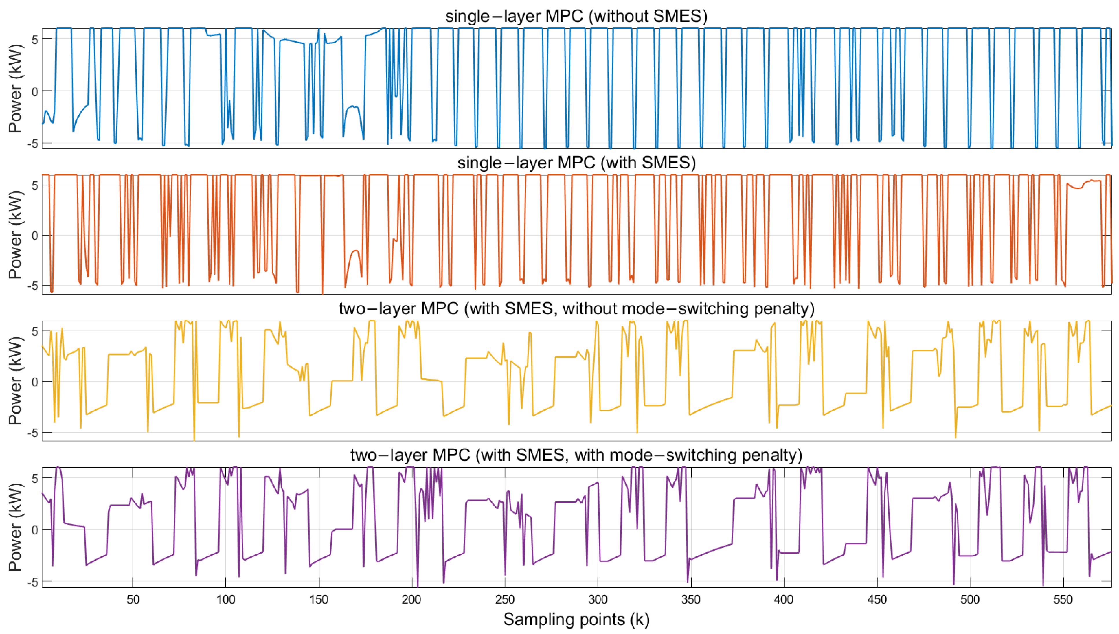
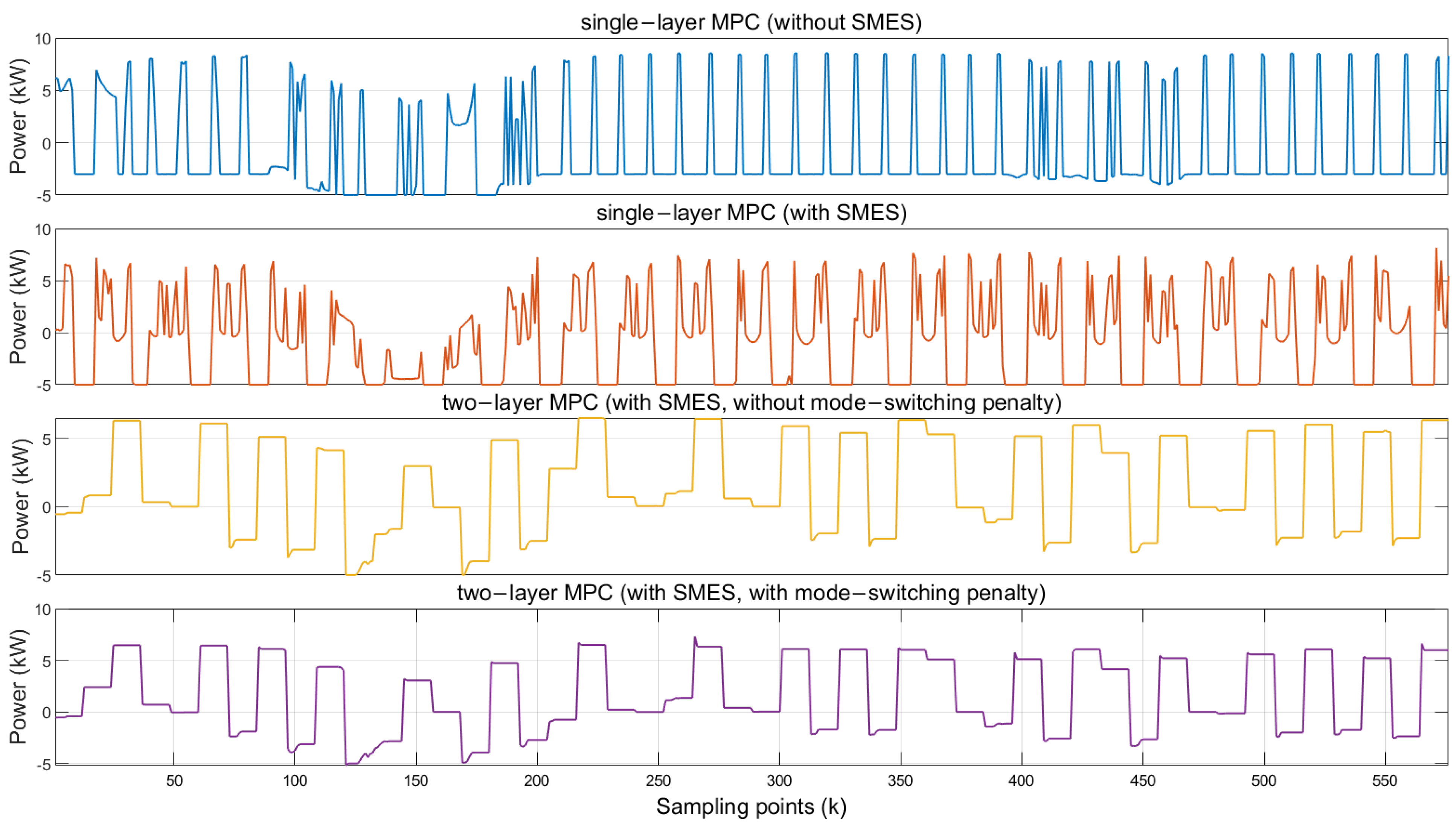
Through MATLAB simulation, comparisons were made between single-layer MPC (without SMES), single-layer MPC (with SMES), two-layer MPC (with SMES, without mode-switching penalty), and two-layer MPC (with SMES, with mode-switching penalty).
Figure 5 and
Figure 6 show the power diagrams of HES and the grid under different conditions. Under single-layer MPC, both HES and grid power exhibit significant sawtooth fluctuations and frequent mode switching. Although adding SMES slightly dampens these spikes, the high-frequency oscillations persist. After switching to dual-layer MPC for HESS output, power output fluctuations are significantly reduced, and the control output exhibited a certain margin, which enhances the system’s robustness and interference resistance. Furthermore, the introduction of mode switching penalties further decreases the frequency of HES mode switching without compromising system robustness and stability.
Comparing average HES power outputs across control states: under single-layer MPC without SMES, the hydrogen fuel cell averaged 3.46 kW; with SMES, this decreased to 3.44 kW. Switching to two-layer MPC reduced average power to just 0.78 kW. This significant decrease in power consumption effectively lowers generation costs while simultaneously providing more stable command outputs.
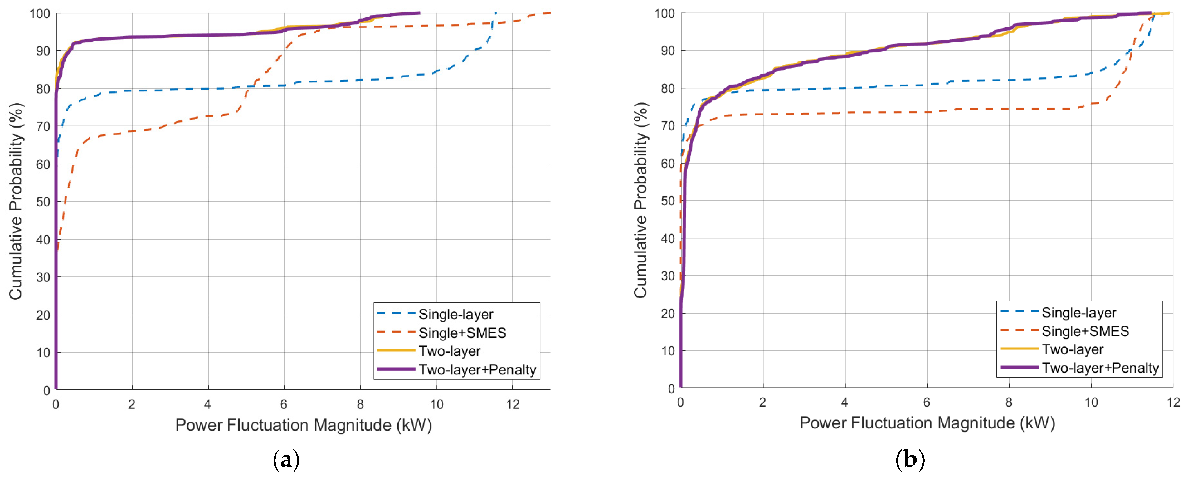
Figure 7 presents the cumulative distribution function (CDF) of power fluctuation magnitude, providing a statistical perspective on system stability. In
Figure 7a, the superiority of the proposed two-layer strategy is evident; the solid curves (yellow and purple lines) exhibit an extremely steep ascent, reaching a 90% probability threshold at a fluctuation magnitude of merely 0.37 kW. In contrast, the ‘Single + SMES’ strategy (orange dashed line) exhibits a slow ascent, requiring a fluctuation magnitude of approximately 6 kW to reach the same probability level. This implies that the proposed strategy reduces routine power fluctuations by a factor of over 16. Furthermore, the solid curves demonstrate an early termination along the x-axis compared to the dashed lines. This indicates that the proposed strategy strictly limits worst-case fluctuations to a safer level of approximately 9.57 kW, whereas single-layer control permits extreme spikes exceeding 11.5 kW.
Figure 7b also reveals the operational characteristics of the HES, demonstrating that this strategy successfully constrains the HES dynamics within a stable low-frequency range, thereby avoiding unnecessary chattering.
Based on analysis of HES power and grid power, the single-layer system without SMES exhibits significant susceptibility to disturbances, transmitting grid fluctuations to the hydrogen fuel cell with virtually no attenuation. The introduction of SMES functions as a high-pass filter, absorbing some high-frequency crosstalk, though its filtering effectiveness is constrained by the optimization capabilities of single-layer control. In contrast, two-layer MPC demonstrates outstanding low-pass filtering characteristics. The upper-layer MPC generates low-frequency power commands, while the lower-layer MPC controls the SMES to actively counteract all high-frequency fluctuations, ensuring greater system stability and enhancing robustness. The introduction of mode-switching penalties reduces the frequency of mode transitions while further improving system stability.
To comprehensively validate the effectiveness of the proposed two-layer MPC strategy, this study established four specific quantitative evaluation dimensions: economic efficiency, dynamic stability, real-time capability, and equipment lifespan degradation. These dimensions were used to conduct comparative tests on different control strategies: single-layer without SMES, single-layer with SMES, two-layer without penalties, and two-layer with penalties. System stability time is defined as the duration the system maintains stable operation throughout the entire 48 h period. Computational efficiency is measured by the total computation time required to complete the full rolling optimization. State transition frequency quantifies the number of switches between hydrogen production and consumption modes in the HES, where high-frequency switching accelerates equipment wear.
To validate the robustness of the proposed two-layer MPC strategy under varying forecast errors, two additional typical power forecast error scenarios were introduced, with overall error levels of ±5%, ±10%, and ±15%.
Table 3 presents the average statistical values of each control performance metric across these three forecast error scenarios. The results demonstrate that even with increased forecast errors, the strategy maintains stable system operation and effectively suppresses power fluctuations.
As detailed in
Table 3, the proposed two-layer MPC strategy significantly improves economic viability. Compared to the single-layer baseline, the optimized hierarchical structure reduced the total operating costs by approximately 55.5%. Although the introduction of the mode-switching penalty incurred a marginal cost increase of roughly 2.7%, this trade-off is justified by the substantial benefits gained in system longevity and stability, as discussed below.
In terms of stability, the two-layer MPC system achieves a 64.2% longer stabilization time compared to single-layer structures, maintaining a stable state throughout most operational cycles.
A critical advantage of the two-layer framework is its computational speed. As shown in the table, the calculation time was reduced by over 97% compared to the single-layer MPC. By decomposing the large-scale optimization problem, the proposed method brings the solution time down to a level feasible for online real-time control, overcoming the computational bottleneck of centralized MPC.
Single-layer controllers induce frequent mode switching, whereas the penalty function approach reduces switching frequency by 59.9%. This results in reduced mechanical stress on the HES and extended service life.
5. Conclusions
This paper proposes a novel approach to address the grid integration challenges of highly fluctuating renewable energy sources. Innovatively replacing traditional battery/supercapacitor architectures, an integrated model of SMES and HES has been established to serve as the foundation for the proposed control strategy. Based on this model, a matched two-layer MPC framework has been designed to achieve efficient coordination across multiple temporal scales: the upper layer optimizes HES scheduling with economic efficiency as the objective, while the lower layer leverages the millisecond-level power response capability of SMES to rapidly smooth fluctuations and compensate for prediction errors in real time.
Simulation results demonstrate that the proposed strategy fully leverages the high power density and rapid regulation characteristics of SMES. While maintaining system stability, it significantly enhances overall economic performance. By incorporating a specific mode-switching penalty term into the optimization objective, the framework reduces HES mode switching frequency by approximately 59.9%, compared to single-layer control. This significant reduction effectively extends equipment lifespan and lowers operational maintenance costs. Furthermore, benefit is also from the hierarchical decoupling, where the lower layer SMES actively compensates for high-frequency transient disturbances, and the system’s overall stable operation time also increases by over 64.2%. This study confirms that integrating SMES into HESS overcomes the limitations of traditional battery/supercapacitor combinations in response speed and cycle life, providing a stable and economically viable energy storage solution for high-penetration renewable energy integration.
However, current research still has limitations that require optimization. Existing control strategies heavily rely on precise mathematical models, but in practical applications, complex electrochemical reactions and environmental fluctuations may cause model parameter drift, thereby affecting control accuracy. Additionally, existing deterministic MPC formulas assume accurate photovoltaic and load forecasting, failing to adequately account for prediction errors in actual operation. To address these limitations, future research will focus on developing adaptive and uncertainty-aware control strategies. By incorporating online parameter estimation techniques to dynamically adjust key HES parameters, controllers can adapt to equipment degradation and environmental changes.
In summary, this work provides a solution for multi-timescale coordinated control of hybrid energy storage systems. Future efforts will further address adaptability challenges, account for environmental uncertainties, and enhance the feasibility and robustness of system operation.