Review

Review and Prospect of Key Technology for HTS Wind Generators of HPOSWP Integrated Systems

by
Yujia Zhai
1,2,3,
Shuai Liu
1,2,3,
Liufei Shen
1,2,3,*,
Long Chen
1,2,3,
Wenjie Zhou
1,2,3,
Cheng Zhang
1,2,3,
Feiyue Shan
1,2,3,
Xingzheng Wu
1,2,3 and
Siyu Duan
1,2,3
1
College of Electrical and Information Engineering, Hunan University, Changsha 410082, China
2
Engineering Research Center of Power Transmission and Transformation Technology, Ministry of Education, Changsha 410082, China
3
State Key Laboratory of Offshore Wind Power Equipment and High-Efficient Utilization Wind Energy, Hunan University, Changsha 410082, China
*
Author to whom correspondence should be addressed.
Energies 2026, 19(6), 1525; https://doi.org/10.3390/en19061525
Submission received: 25 January 2026 / Revised: 19 February 2026 / Accepted: 18 March 2026 / Published: 19 March 2026
(This article belongs to the Section F: Electrical Engineering)

Abstract

As offshore wind power develops toward larger unit capacities and deeper offshore deployments, its inherent power intermittency poses increasing challenges to system stability and reliable grid integration. To address the issues of large-scale wind power fluctuation and efficient energy utilization, an integrated hydrogen production through offshore superconducting wind power (HPOSWP) system is investigated, which combines high-temperature superconducting (HTS) wind generators with water electrolysis. This paper reviews the operational characteristics of the HPOSWP system under wide power fluctuation conditions, specifically assessing the adaptability of high-power-density HTS wind generators and the feasibility of highly reliable liquid hydrogen (LH2) circulation cooling technologies from a qualitative perspective. This study provides valuable insights into the application of large-scale HPOSWP systems under fluctuating power conditions and establishes a solid theoretical foundation for subsequent system design and engineering implementation.

1. Introduction

As the global energy transition accelerates toward renewable energy systems, offshore wind power has attracted increasing attention due to its vast resource potential and independence from land-based constraints [1,2,3]. With the continuous development of offshore wind technology toward larger unit capacities and deeper water deployment, conventional wind turbine generators face growing challenges related to excessive weight and volume, which impose significant constraints on maritime transportation, installation, and maintenance. Meanwhile, the inherent intermittency and volatility of offshore wind resources exacerbate power fluctuation issues, leading to grid instability and substantial curtailment rates. To address these dual challenges, an integrated hydrogen production through offshore superconducting wind power (HPOSWP) structure has been proposed by the State Key Laboratory of Offshore Wind Power Equipment and High-Efficient Utilization Wind Energy at Hunan University [4,5]. By integrating high-temperature superconducting (HTS) wind generators with water electrolysis hydrogen production technology, this concept enables the local conversion of offshore wind energy into liquid hydrogen (LH2), which can be stored and transported efficiently. Moreover, a portion of the produced LH2 is utilized in a controlled circulation loop to provide cryogenic cooling for the HTS wind generators, thereby forming a tightly coupled system [6,7]. This integrated approach offers the potential to reduce platform weight and volume, enhance energy conversion efficiency, and improve system-level operational reliability.
During the operation of integrated systems, the HTS turbine generates a substantial heat load due to its structural characteristics. Moreover, under conditions of wide power fluctuations (power decreasing from 100% to as low as 10% of rated capacity within minutes, with frequent start–stop cycles, e.g., more than two times per day [8,9]), the turbine undergoes frequent starts and stops, and the relative rotating magnetic field between the stator and rotor induces additional losses in the field windings [10]. Both steady-state and transient heat loads require rapid and efficient dissipation, which reduces the overall energy utilization efficiency of the system and poses a threat to its operational stability [11]. Prior studies have validated the feasibility of standalone HTS wind generators [12,13,14] and demonstrated the applicability of LH2 cooling for superconducting devices [15,16,17]. However, existing research primarily focuses either on isolated HTS wind generator performance or independent offshore wind hydrogen production. Particularly, limited research has investigated the integrated operation of HTS wind turbines and hydrogen production technologies or the use of LH2 for cooling HTS wind turbines to enhance overall energy efficiency. This lack of an integrated perspective constitutes a significant research gap for HPOSWP systems. Furthermore, the absence of established technical specifications or standards poses a major challenge to the development of such integrated configurations.
Therefore, this paper reviews the operational characteristics of the integrated HPOSWP system under wide power fluctuations, conducting a qualitative assessment of the feasibility of HTS wind generators and LH2 circulation cooling technologies to establish a robust framework for future deployment. The remainder of this paper is organized as follows: Section 2 delineates the HPOSWP architecture and qualitatively assesses structural adaptability under wide power fluctuations. Section 3 presents a qualitative comparative review of diverse superconducting topologies, discussing their performance in mitigating transient thermal loads during power surges, thereby illustrating the superior power density and adaptability of HTS machines. Section 4 discusses the challenges associated with achieving efficient and reliable LH2 circulation cooling and conducts a qualitative investigation of the feasibility of novel hybrid cooling solutions. Finally, Section 5 summarizes the technological challenges and the future development directions for the HPOSWP integrated systems.

2. Innovative HPOSWP Integrated Technology

The innovative HPOSWP integrated system replaces the conventional copper windings of wind generators with HTS tapes. Owing to their zero-resistance characteristics, superconducting coils significantly increase the power density, enabling a reduction in generator weight to 1/3 or even 1/2 of that of conventional machines with comparable ratings. For example, taking the NREL reference turbine (REpower 5MW) as the benchmark for conventional technology, Abrahamsen et al. [18,19] proposed a 5 MW HTS direct-drive generator (24-pole, radial synchronous structure). By replacing conventional copper windings with HTS tapes, the HTS wind generator, including the cryostat, weighs only 34 tons, whereas the combined weight of the generator and gearbox in the REpower 5MW turbine amounts to 80 tons. This substantially reduces the construction difficulty of offshore power generation systems. Moreover, HTS wind generators feature low synchronous reactance, low harmonic distortion, and reduced thermal fatigue in the field windings, which substantially improves wind energy efficiency [20].
By converting offshore wind power into hydrogen, the HPOSWP integrated system eliminates the need for subsea transmission cables and grid-connection infrastructure. This approach significantly reduces reliance on subsea electrical transmission while retaining only minimal low-power cables for control, data communication, and emergency backup. The produced hydrogen can be transported ashore via ships or pipelines, thereby avoiding the substantial transmission losses typical of deep-sea electrical systems. Taking remote offshore wind farms in the North Sea as an example, for large-scale energy transmission, the investment cost per unit of energy transported via hydrogen pipelines is an order of magnitude (10 times) lower than that of subsea cables. Meanwhile, if relying on subsea cables for transmission, remote offshore wind power incurs a 12–20% wind curtailment rate due to transmission capacity limitations, which drives up the levelized cost of electricity of wind power. Additionally, subsea cables are prone to seawater corrosion, with operation and maintenance (O&M) costs accounting for a relatively high proportion of the full-life-cycle costs. In contrast, hydrogen transmission pipelines can be repurposed from existing natural gas pipelines, and their O&M technology is more mature [21].
The integration of HTS wind turbines with LH2 production provides distinct advantages [22]. By leveraging the critical-current–temperature dependence of second-generation (2G) HTS tapes, a small amount of stored LH2 at 20 K provides the cryogenic environment required for high-field operation. With a structural design similar to that of liquid-helium cryostats, the high specific heat capacity and ultralow temperature of LH2 enable superconducting coils to operate at current levels an order of magnitude higher than those cooled by liquid nitrogen, thereby further increasing the system power density. Moreover, LH2 circulation cooling technology eliminates the need for a cryogenically independent, dedicated cryogenic system that is physically and energetically decoupled from the offshore hydrogen production and storage subsystem. Under conventional offshore superconducting wind power generation approaches, such an independent cryogenic system would otherwise be required solely for cooling the HTS wind generator. This integrated cooling configuration retains core cryogenic components and safety systems necessary for LH2 circulation and heat dissipation, while significantly reducing cooling costs and system complexity and enhancing the integration level of offshore wind-hydrogen platforms.
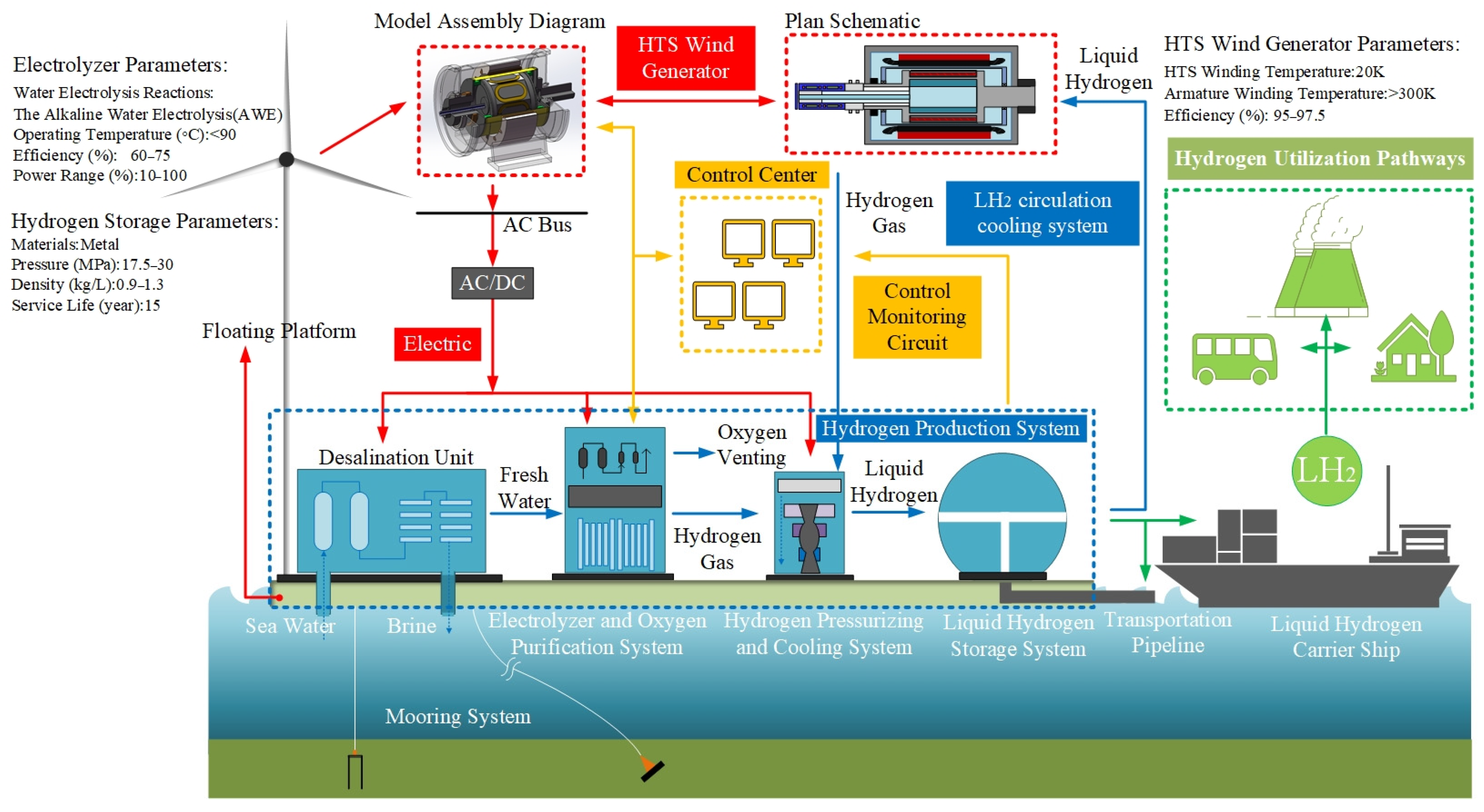
Figure 1 illustrates the dynamic control logic of the integrated system. Owing to the high level of integration on a floating platform, the output of the offshore wind farm is subject to random fluctuations driven by the inherent variability of wind resources. This variability is further exacerbated by the influence of ocean waves on part of the turbine array, increasing the overall uncertainty of power generation. To reduce the substantial horizontal loads and overturning moments acting on offshore wind turbines, the integrated system adopts a modular architecture that decreases equipment complexity and minimizes overall system volume. Based on its functional decomposition, the HPOSWP integrated system comprises four major subsystems: the HTS wind power system, the electrolytic water hydrogen production (EWHP) system, the LH2 storage system, and the LH2 circulation cooling system. The HTS wind power subsystem converts offshore wind energy—characterized by wide power fluctuations—into electrical energy, which is subsequently transformed into hydrogen through the EWHP subsystem [23]. The generated LH2 is transported to land via carrier ships or hydrogen pipelines [24], while a small portion is diverted into the circulation loop to support system operation. This diverted LH2 provides the cryogenic environment required by the offshore HTS wind turbine and enables power-to-heat conversion, thereby enhancing system integration. Through the internal conversion and storage units, the power generation subsystem achieves coupled multi-energy conversion with the hydrogen production subsystem via power conversion technology. Their mutual interactions and operational constraints facilitate cascade energy utilization across the integrated system. This synergistic relationship further optimizes the system architecture and functional behavior, providing an innovative technological pathway for the efficient exploitation of wind resources.
For stable system operation, the LH2 circulation system must provide continuous cooling to maintain the deep cryogenic environment of the HTS wind generator. To reduce the cooling power demand and enhance the overall energy efficiency, a systematic analysis of the HTS wind generator topology is required. This involves developing a high-power-density and highly compatible design to effectively minimize thermal load generation. Furthermore, the LH2 refrigeration equipment is essential for maintaining the safe, reliable, and stable operation of the HTS wind generator. When designing the LH2 cooling system, the thermophysical properties of the cryogenic coolant and the operational requirements of the HTS wind generator must be considered, as these factors are crucial for achieving rapid heat dissipation, which is key to resolving thermal stability issues.
Sun et al. [25] conducted a thermal analysis on a single superconducting coil in a 550 kW superconducting wind turbine. The superconducting coil operates at 20 K, while the conventional armature winding temperature exceeds 300 K. Through the dual attenuation of an 80 K actively cooled shield and 20 layers of multilayer insulation, the radiative heat leakage stabilizes at 0.1 W. Additional thermal loads include AC losses induced by stator harmonics (approximately 1.25 W), conductive heat from current leads and titanium alloy support structures (approximately 0.79 W), and unstable heat generated by the relative rotating magnetic field between the stator and rotor under fluctuating operating conditions, estimated at 1.2–1.4 W. In the HPOSWP integrated system, insufficient vapor recondensation efficiency in the LH2 cooling system leads to a continuous rise in ambient temperature surrounding the coil, preventing the HTS wind turbine from maintaining stable operation. Conversely, if the cooling capacity of the refrigeration system significantly exceeds the total thermal load of the HTS coil, two-phase flow instability may occur in the cooling loop. This is because the excessive cooling power causes rapid and uneven recondensation of LH2 vapor, leading to alternating liquid-vapor slugs in the pipeline, pressure fluctuations, and reduced heat transfer uniformity [26]. Such instability can induce local hot spots or excessive cooling of the HTS coil, resulting in operational instability or malfunction of the superconducting turbine. Therefore, from a technical perspective, achieving stable operation in HTS wind turbines necessitates both a highly adaptable, low-loss machine configuration and a highly efficient, reliable LH2 circulation refrigeration system. This paper conducts a comprehensive analysis of HTS wind generators and discusses candidate configuration options by comparing structural thermal loads, thereby enhancing the adaptability of high-power-density HTS wind generators in integrated systems.

3. High-Power-Density and High-Adaptability Offshore HTS Wind Generators

3.1. Offshore High-Power-Density HTS Wind Generators

Following breakthroughs in 2G HTS materials and advancements in cryogenic cooling technology, HTS electrical equipment has experienced rapid development [27]. By replacing conventional copper coils with HTS tapes, high-power-density HTS wind generators achieve significant reductions in size and weight while improving efficiency [28], positioning them as a key focus of global research. In 2002, Siemens completed the conceptual design of a 4 MW HTS synchronous generator [29] and successfully connected it to the power grid, demonstrating the practical feasibility of superconducting technology in large-scale power generation. In 2007, Technova designed a 20-pole, 8 MW HTS wind generator and conducted studies on the influence of structural and electromagnetic parameters on overall system performance, providing a significant theoretical basis for subsequent HTS wind generator development. In the same year, Converteam initiated the design and development of an 8 MW direct-drive HTS wind generator [30]. These efforts, combined with extensive theoretical research on HTS wind generator design, have played a pivotal role in accelerating the global advancement of HTS power generation technologies.
In 2010, AMSC developed an HTS direct-drive wind generator that significantly accelerated the commercialization of superconducting wind power technology. The generator weighed approximately 180 tons—only 50% of the mass of a conventional permanent-magnet direct-drive generator of the same rating—while its diameter was reduced from roughly 10 m to 4.5–5 m [31]. In 2011, the Technical University of Denmark introduced the Superwind 5 MW HTS wind generator, further validating the feasibility of 2G-HTS machines in terms of both weight reduction and cost competitiveness [18,32]. In 2019, the success of the EU EcoSwing project marked a major milestone toward the commercial deployment of HTS wind generators. The EcoSwing 3.6 MW generator [12,13,14] employed 2G-HTS coils for its field windings, while the stator retained a conventional copper armature. The HTS coils were maintained at approximately 30 K via conduction cooling, with the rotor’s thermal load transferred through a copper thermal bus to a rotating cryocooler. During performance testing, the generator operated continuously for more than 650 h and produced over 600 MWh of cumulative electricity [14]. Its subsequent connection to the commercial grid on the west coast of Denmark provided the first real-world validation of the feasibility and reliability of HTS wind generators for offshore wind power applications.
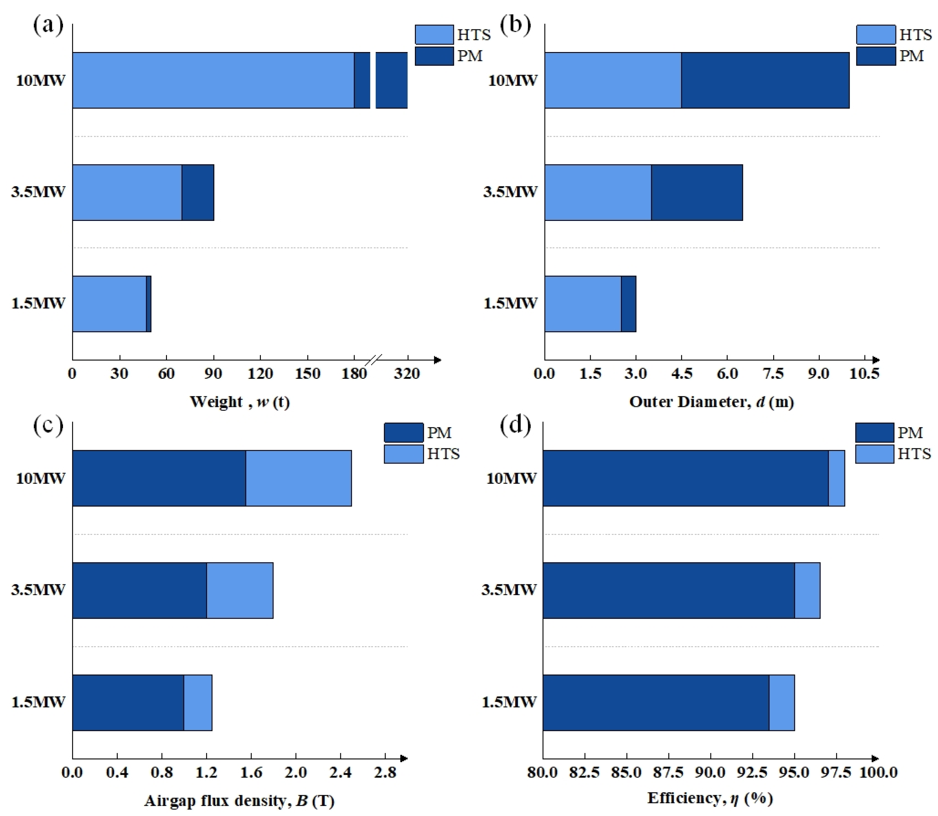
In recent years, extensive global research on HTS wind generators has further established a viable technological pathway for the lightweight design of large-capacity offshore wind turbines. As illustrated in Figure 2, the performance metrics of HTS wind generators tend to outperform those of conventional permanent-magnet (PM) machines of equivalent capacity. Hoang et al. [33] further compared HTS and PM generators across a capacity range of 2–23 MW, revealing that in the medium-to-high power segment (rated power ≥ 8 MW), HTS generators achieve a significantly lower levelized cost of energy (LCOE). At 20 MW, the LCOE of the HTS generator is approximately 7% lower than that of the PM generator. The advantages of superconducting machines become even more pronounced at power levels above 10 MW [34].

3.2. Offshore High-Adaptability HTS Wind Generators

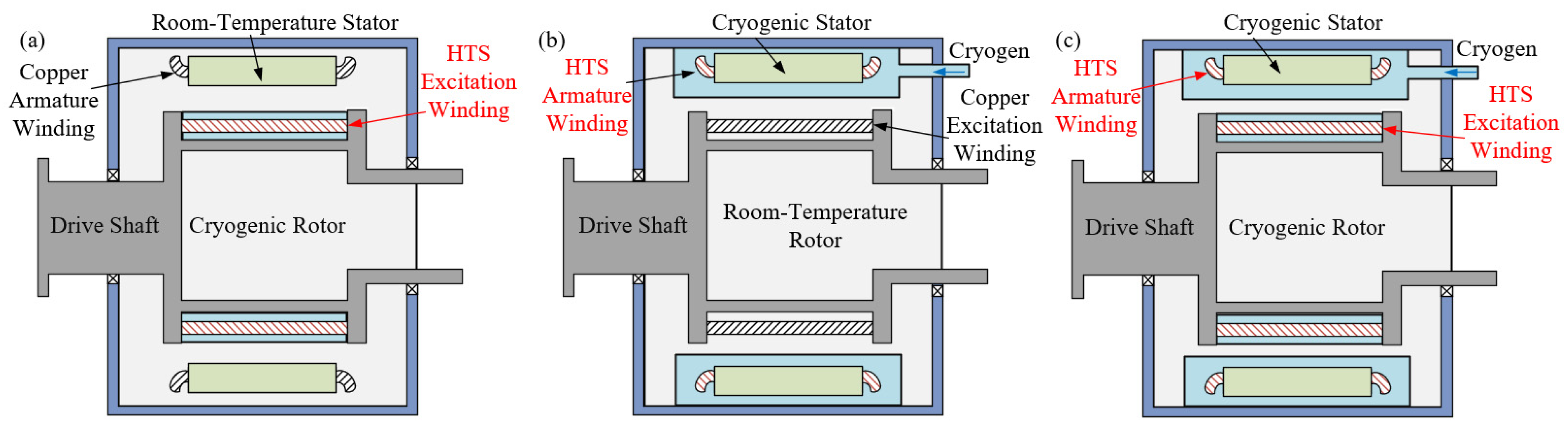
Owing to the substantial heat loss experienced by HTS wind generators under wide power fluctuation conditions—which significantly reduces the overall energy efficiency of the integrated system—this paper categorizes HTS wind generators into three types based on the dominant heat source location: rotor superconducting generators, stator superconducting generators, and fully superconducting generators, as illustrated in Figure 3.
In rotor superconducting generators, the field winding typically employs HTS tapes, while the stator retains conventional copper armature windings. This configuration fundamentally eliminates AC transport losses in the HTS tapes, and the cryogenic cooling system is required only to maintain the rotor at low temperature. The EU’s SupraPower 10 MW direct-drive wind generator [36,37] has demonstrated the feasibility of HTS field-winding technology, establishing a foundation for the design of full-scale prototypes. However, this topology requires a cryogenic coupling mechanism to deliver both cryogenic coolant and field current to the rotating rotor. The rotating cryogenic container and the stationary cryocooler must be connected by a dynamic seal to prevent leakage of the cooling working fluid and minimize heat ingress [38]. The dynamic sealing structure increases the complexity of the cooling system and must maintain high reliability under long-term operational vibration. The complexity and stringent reliability requirements of large-scale systems have hindered the technological development of rotor superconducting generators.
Stator superconducting generators employ a static sealed coupling technology. By fixing the superconducting armature winding on the stator side, this configuration eliminates the need for a rotational cryogenic coupling device. The superconducting winding is cooled through a static sealed coupler connected to an external cryocooler, which substantially simplifies the overall system architecture. In this design, the rotor employs conventional copper windings and an iron core, while the superconducting armature winding is mounted on the stationary main shaft using non-magnetic support structures to enable static sealed cooling of the HTS tapes. However, the HTS armature windings carry AC current and operate within the rotating magnetic fields generated by both the stator and rotor. The combined interaction of AC transport current and time-varying magnetic fields results in substantial AC losses in the HTS tapes. M. Fee et al. [39] analyzed the AC losses of their designed 2 MW direct-drive stator semi-superconducting generator, which consists of a multi-pole permanent-magnet rotor and HTS stator coils. Operating at 20 rpm, 50 Hz, the AC loss of the superconducting coils is calculated to be 15.1 W/m, with a total AC loss per phase reaching 285 W. At the typical operating temperature range of 30–77 K for HTS wind turbine generators, this AC loss corresponds to a required refrigeration power of 17 kW (based on a cryogenic specific power of 20, defined as the ratio of refrigeration input power to the heat load removed at cryogenic temperature), significantly increasing the cooling load necessary for stable operation. This high heat-loss burden constitutes the primary limitation of the stator superconducting generator. Currently, this configuration remains confined to small-scale prototype development, with no large-scale commercial deployment in wind power systems.
In fully superconducting wind generators, both the stator and rotor windings are constructed using HTS tapes. Owing to the high current-carrying capacity of HTS tapes, fully superconducting wind generators achieve substantially higher power density than their semi-superconducting counterparts, enabling significant reductions in machine size and weight [40]. As an example, the 10 MW fully superconducting generator designed by AML has a total mass of only 70 tons—40% of the weight of AMSC’s 10 MW semi-superconducting machine [41]. Despite these advantages, the armature winding in a fully superconducting generator experiences considerable AC losses. Although MgB2 superconductors have been adopted for armature windings to mitigate AC losses because of their low hysteretic characteristics [42], their allowable magnetic field strength remains limited. Furthermore, the cryogenic cooling system for a fully superconducting wind generator is highly complex. The rotor requires a dynamic rotating seal to transfer cryogenic coolant, while the stator must be equipped with a high-power cooling system to dissipate the substantial AC losses in the superconducting armature. The close electromagnetic coupling between the superconducting field and armature windings further complicates the thermal and structural design of the entire cryogenic system. This interaction results in an extremely complex cryogenic cooling system architecture for the fully superconducting topology. Nakamura et al. [43,44] developed a 50 kW fully superconducting wind generator prototype based on 2G YBCO tapes and conducted light-load performance tests. However, due to the significant challenges associated with mechanical design, thermal management, and system integration, fully superconducting wind generators have not yet reached commercial deployment and remain confined to laboratory-scale research and development.
Table 1 compares three different HTS wind generator structures. In a statically sealed superconducting wind generator, the superconducting armature winding is fixed on the stationary stator side, while the armature reaction field rotates synchronously. In this configuration, the armature winding is continuously exposed to an alternating magnetic field, resulting in significant AC losses. Moreover, within an integrated system operating under wide power fluctuations, transient events such as start-up, shutdown, and short-circuit faults induce a sharp rise in short-circuit current. The consequent thermal load reduces the energy efficiency of the integrated offshore system, rendering stator superconducting generators unsuitable for harsh and complex marine environments. Although the fully superconducting generator provides theoretically optimal electromagnetic performance, its cryogenic system is extremely complex. The need for both a rotating dynamic seal on the rotor side and a high-capacity cooling system on the stator side complicates manufacturing, operation, and maintenance. These challenges severely limit its applicability in HPOSWP-integrated systems.
In contrast, dynamically sealed superconducting wind generators provide distinct advantages for integrated offshore applications. Under normal operating conditions, the superconducting field winding rotates synchronously with the conventional armature winding, resulting in a quasi-stationary relative position between field and armature windings. Consequently, the fundamental component of the armature reaction field does not induce hysteresis loss in the superconducting field winding. Only under transient conditions—such as during faults or sudden power fluctuations that generate relative rotating fields—are additional AC losses produced, and these constitute only a small fraction of the total thermal load. Therefore, the required cooling capacity of the LH2 circulation system is significantly reduced, lowering the operational cost while enhancing the overall efficiency and reliability of the integrated offshore energy system.
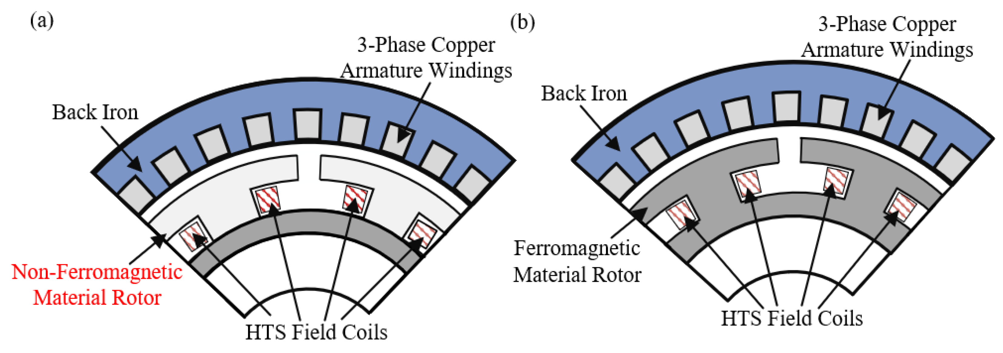
The high critical current density of HTS tapes enables the magnetic field in rotor superconducting generators to exceed the limits of conventional electromagnetic materials, reaching levels above 2T. The FP7 SupraPower project [36,37] and the “FP7 INNWIND.EU” project [25] have demonstrated the advantages of superconducting generators in high-field applications, validating their potential to achieve significantly higher power density. However, the performance of these machines is constrained by the B–I dependence of ferromagnetic core materials. As the magnetic field increases, the core experiences excessive magnetic saturation, causing core losses to greatly exceed the thermal losses of the superconducting windings. Consequently, this substantially increases the heat load on the cryogenic cooling system and prevents the generator from fully utilizing the magnetic-field advantages of HTS technology. Furthermore, because the ferromagnetic core is in direct contact with the superconducting windings, the core losses elevate the local operating temperature of the coil. This temperature rise reduces the critical current of the HTS tape and significantly increases the risk of quench. To mitigate these issues and further reduce rotor-side heat losses, many HTS wind generators employ non-ferromagnetic structural materials [47]. As illustrated in Figure 4, this approach not only reduces overall weight but also eliminates magnetic saturation and fundamentally suppresses core losses, thereby reducing the demand on the refrigeration system. This air-core structure has already been adopted in several large-scale HTS propulsion motors, such as the 5 MW HTS ship propulsion motor developed by AMSC, the 1 MW model developed by China’s 712 Institute [48], and the 3 MW model developed by Kawasaki Heavy Industries [49].
Considering the severe heat loss challenges caused by wide power fluctuations in integrated offshore systems, the rotor superconducting air-core topology has emerged as a highly adaptable and robust configuration. It avoids AC transmission losses in the rotor windings and completely eliminates iron-core losses, enabling more stable and efficient operation of high-power-density HTS wind generators. However, because the air-core rotor introduces high magnetic reluctance into the field magnetic circuit, a substantially larger amount of superconducting material is required to generate the strong field needed for generator operation, which poses a major challenge in terms of manufacturing costs. Furthermore, the significant spatial separation between the stator and rotor magnetic circuits results in considerable leakage flux in the rotor windings. Additionally, the non-uniform magnetic field distribution produced by the rotor introduces high-order harmonic components into the induced voltage of the armature windings, thereby degrading the overall electromagnetic performance of the wind generator. These challenges underscore the need for further research on optimized magnetic circuit design and harmonic suppression strategies to improve the feasibility of rotor superconducting air-core wind generators for integrated offshore systems in the future.

4. High-Efficiency and High-Reliability LH2 Circulation Cooling System

The cooling system of HTS wind generators is primarily composed of two subsystems. Currently, the stator cooling systems of most HTS wind generators continue to employ conventional cooling methods, such as water cooling and forced-air cooling [50]. Consequently, the cryogenic cooling system for the rotor emerges as the critical focus in the thermal management design of superconducting turbines.
Under load, a HTS wind generator produces various forms of heat, including steady-state heat loads—such as radiative heat [51], conductive heat, and harmonic losses [52]—as well as transient heat loads, notably the AC losses of the HTS coils. The steady-state heat load of the HPOSWP-integrated system can be reduced by structural optimization and shielding measures, such as the addition of a damping layer [53], but it cannot be completely eliminated. The cryogenic cooling system must dynamically match its cooling capacity to the total thermal load. During operation, the refrigerant absorbs heat within the cryogenic environment and is transferred into the rotor cooling loop via a heat-exchange coupler, thereby maintaining the superconducting state of the rotor coil. In essence, the thermal management challenge in superconducting turbines is fundamentally a problem of providing stable and efficient cryogenic cooling for superconducting magnets under complex operating conditions. Therefore, the development of a high-efficiency, high-reliability LH2 circulation cooling system is crucial to ensuring the stable and efficient operation of high-power-density HTS wind generators. Hirabayashi [15] investigated the potential for using LH2 in superconducting energy storage systems. Nakayama [16] established the economic viability of using hydrogen cooling for future superconducting technologies. Shirai [17] predicted the heat transfer of natural convection in saturated LH2, providing fundamental data that supports the development of LH2 cooling technology.
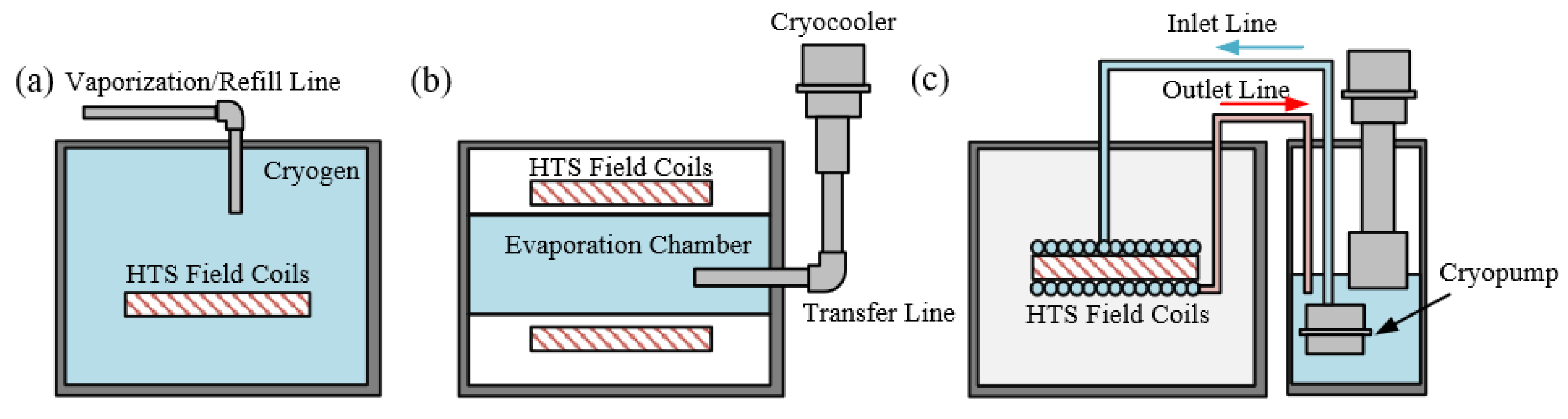
With the development of cryogenic refrigeration technology, circulation cooling methods can be categorized into three primary types based on the phase-change or convective heat transfer characteristics of the coolant: immersion cooling, rotating heat pipe cooling, and forced convection cooling, as illustrated in Figure 5. However, whether these cooling methods are suitable for HPOSWP integrated systems lacks systematic clarification. The discussion should be centered on the core operational demands of HPOSWP integrated systems and cover the following performance indicators: cooling capacity matching the dynamic thermal load of HTS generators under wide power fluctuations, uniformity of temperature difference in HTS windings, transient heat transfer response speed for rapid dissipation of sudden AC losses, and safety considerations regarding LH2 as a cooling medium.
Immersion cooling features a simple structural design and utilizes the latent heat of phase change in superconducting coils immersed directly in a cryogenic medium. This approach provides a large contact area and high heat-transfer efficiency, and it avoids the need for complex cooling circuits, which has led to its widespread adoption in low-speed HTS turbines. Hara et al. [26] presented the design of an LH2 cooling system for their HTS wind generators, in which the superconducting excitation windings are directly cooled by immersion in LH2. The evaporated hydrogen, after cooling the armature coils and other components, is directed to an exhaust channel for potential energy utilization. By deploying eight thermometers and two MgB2 superconducting level gauges inside the rotating tank to monitor the LH2 conditions, this cooling system maintains a stable LH2 liquid level in the tank at rotational speeds ranging from a minimum of 900 rpm to a maximum of 1800 rpm. However, maintaining hydrogen in the liquid state presents significant challenges. To evaluate the feasibility of using LH2 as a refrigerant, Nam et al. [54] designed a hydrogen cooling system for an aerospace propulsion superconducting machine, employing indirect cooling. The LH2 cooling unit was constructed and experimentally validated, confirming that LH2 can function both as an energy carrier and as an effective refrigerant. Additionally, M. Ohya [55] conducted immersion cooling tests on the LH2-cooled HTS coil of a 10 kW HTS wind generator. No measurable heat loss was observed at a generation voltage of 0.8 mV, further demonstrating the feasibility of LH2 immersion cooling for HTS wind generator applications. Despite these advantages, safety risks constitute the primary limitation of immersion cooling. Under atmospheric pressure (1 atm) and ambient temperature (25 °C), the minimum ignition energy (MIE) of a hydrogen-air mixture is approximately 0.02 mJ at a hydrogen volume fraction of ~29% [56]. This extremely low MIE makes the mixture highly susceptible to ignition by static discharge or electrical sparks within the confined environment of a generator. Consequently, the cryogenic chamber must be engineered as a pressure-resistant vessel, which complicates the dynamic sealing structure and reduces overall system reliability. These constraints significantly limit the applicability of LH2 immersion cooling in large-scale HTS wind generators.
The rotating heat pipe cooling method consists of a rotating evaporator and a stationary condenser. During operation of the HTS wind generator, the coolant in the rotor vaporizes after absorbing heat. The vapor is liquefied by a cryocooler and flows back to the rotor, achieving a self-circulation that avoids the risk of LH2 directly contacting the heat source. The 4 MW HTS wind generator in Germany adopts a GM cryocooler and rotating heat pipe cooling solution. This system features a simple circulation loop, high cooling efficiency, and excellent self-circulation capability, achieving two years of fault-free operation. However, its performance relies on a precise match among the coolant charge amount, rotor speed, and thermal load, resulting in high control complexity [29]. Moreover, the performance of rotating heat pipe cooling is highly dependent on the generator speed. For instance, experimental studies by Zhu et al. [57], conducted within a speed range of 100–400 r/min, demonstrated significant sensitivity of the heat pipe to rotational speed. When the rotor speed falls below 200 r/min, the centrifugal force becomes insufficient to effectively drive the working fluid back to the evaporation section, leading to inadequate liquid supply at the hot end and a 15–25% reduction in the Nusselt number. Once the speed exceeds 300 r/min, the fluid reflux is fully enhanced, and the equivalent thermal conductivity tends to saturate. In an integrated system subject to wide power fluctuations, the HTS wind generator may frequently operate at low rotational speeds. Consequently, this cooling method becomes unable to reliably maintain stable operation of the generator.
To enhance cooling efficiency, The36.5 MW superconducting motor manufactured by AMSC [58] employs a cryogenic pump to circulate the coolant. The coolant is driven through refrigeration pipes for convective heat transfer, carrying away the heat from the HTS tapes before returning to the cold source, forming a closed-loop cooling system. During operation, the adjustable flow rate of forced convection cooling enables it to accommodate significant fluctuations in thermal load, achieving rapid elimination of sudden heat surges in cryogenic environments and thereby ensuring that the superconducting windings remain at a stable operating temperature. G. Seo et al. [59] employed a cryogenic blower to achieve forced convection helium cooling for the superconducting excitation coil. Preliminary experimental results confirmed the capability of this cooling system to rapidly eliminate transient heat surges. When a transient heat load of 11.1–17.6 W was applied to simulate the thermal surge of the module coil under a helium flow rate of 7 g/s (8.2 bar), no significant temperature fluctuation was observed in the system. For the design of cooling systems for large HTS magnets using indirect or inner conductor cooling, an understanding of forced convection heat transfer in LH2 is essential. Experiments on steady-state heat transfer in LH2 pools at near atmospheric pressure have been carried out by several researchers [60,61,62]. Researchers [63,64] investigated the forced convection heat transfer in cryogenic hydrogen under supercritical conditions, focusing on cooling systems operating near the metallic temperature limit. Their work provides a fundamental dataset for heat transfer in forced-flow LH2.
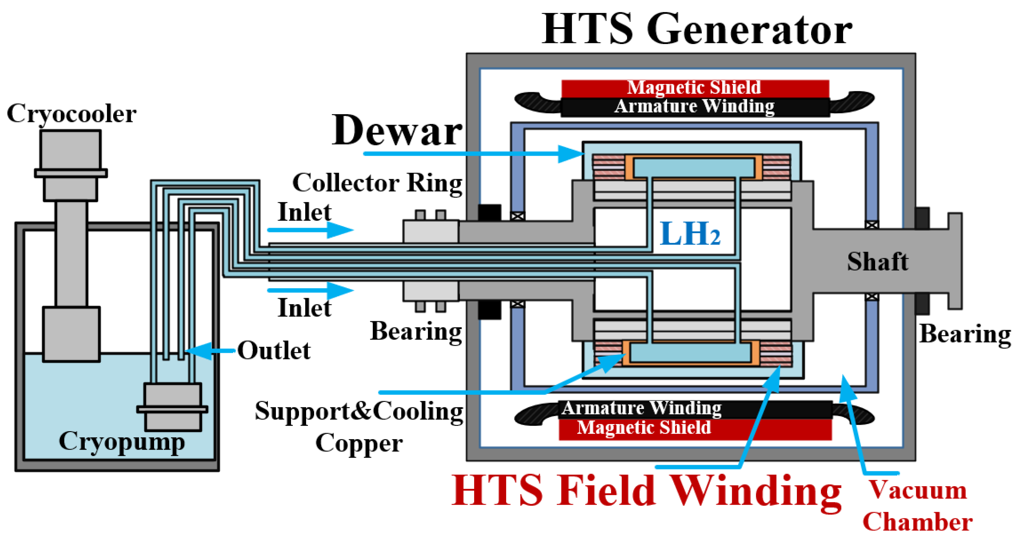
Due to the temperature gradients introduced by conduction-based pipe cooling, the superconducting field winding experiences slow heat transfer in regions far from the cooling channel. Under transient conditions, these regions are prone to the formation of hot spots, where heat cannot be removed in time, leading to a quench in the local section of the coil. To address this issue, Hunan University proposed a novel LH2 circulation cooling scheme that integrates forced convection with conduction cooling, as illustrated in Figure 6. In wide power fluctuation integrated systems, the HTS wind generator experiences strong electromagnetic disturbances, including numerous high-order harmonics and alternating magnetic fields within the flux loop. These disturbances induce significant AC losses in the superconducting coils. The inner layers of the excitation winding, where the critical current density is lower, are particularly susceptible to quenching. To mitigate this risk during operation, LH2 is driven by a cryogenic pump through the cooling channels and into the Dewar, providing low-temperature forced convection cooling directly to the inner surface of the field winding. Meanwhile, leveraging the inherent temperature gradients within the winding, the research team incorporated conduction cooling technology [65,66] into the pipe-cooling design. Owing to the efficient heat-spreading characteristics of conduction cooling, heat generated in any part of the excitation coil is redistributed across the entire cooling structure. Forced convection rapidly responds to transient thermal loads, while conduction cooling dissipates heat and eliminates temperature gradients. The synergy between these two mechanisms prevents the formation of local hot spots. This approach effectively addresses the shortcomings of single cooling methods (such as slow response or uneven heat dissipation), significantly enhances quench tolerance, and provides a robust foundation for the reliable operation of LH2 circulation cooling systems in HTS wind turbines.

5. Future Directions

5.1. HTS Wind Generator Technology

The rotor superconducting air-core structure of generators leads to an uneven magnetic field distribution in the superconducting field winding. This non-uniformity induces significant harmonics in the stator armature’s induced voltage, causing the air-gap magnetic field to deviate significantly from a sinusoidal waveform. The presence of high-order harmonics in the air gap generates additional AC losses in the field winding, thereby increasing the overall heat load of the generator. To mitigate these issues, multi-objective optimization of the excitation coil geometry has proven effective in improving the uniformity of the magnetic field, enhancing the field strength, and reducing the harmonic content in the air gap. Such optimization directly suppresses the formation of heat sources in the superconducting winding. Additionally, electromagnetic shielding is commonly employed to reduce the influence of the stator’s harmonic fields on the field winding. This method typically involves placing a highly conductive metallic cylinder in the air gap to attenuate time-varying magnetic fields. Although current shielding designs in superconducting wind turbines can effectively suppress most harmonic components, their attenuation capability is limited for low-frequency harmonics arising from slow torque fluctuations and high-frequency harmonics generated during frequent start–stop operations. Moreover, the addition of a shielding layer increases the mass of the machine, reducing the power density and hindering the lightweight development of superconducting wind turbines. Therefore, to improve shielding performance while minimizing adverse impacts, multi-objective optimization is applied to parameters such as shielding thickness, placement, and topology. Meanwhile, the development of new composite shielding materials with high electrical conductivity, low density, and excellent cryogenic mechanical properties is essential for achieving efficient and stable operation of high-power-density superconducting wind turbines.

5.2. LH2 Circulation Cooling Technology

Non-contact magneto-hydrodynamic (MHD) seals employ magnetic fluids to form a continuous liquid barrier within a strong magnetic field gradient, thereby achieving sealing without the mechanical wear associated with conventional cryogenic mechanical seals. However, when applied to LH2 systems, direct interaction between the MHD sealing fluid and the cryogenic hydrogen introduces interface instabilities, resulting in reduced pressure resistance and compromised sealing performance. To enhance the safety and reliability of LH2 circulation cooling systems, isolated MHD seal structures that prevent direct contact between the MHD fluid and the LH2 are a viable option for adoption. Such designs increase the pressure resistance of the sealing fluid. Additionally, the development of specialized high-performance sensors capable of continuously monitoring critical potential leakage points, including sealing interfaces, represents an important research direction for enabling the large-scale deployment of integrated superconducting wind power hydrogen production systems.

6. Conclusions

This paper explores the architectural configuration and operational feasibility of an integrated HPOSWP system and conducts a systematic identification and preliminary analysis of the key technical challenges faced by the application of HTS wind turbines and LH2 circulation cooling systems in this integrated system.
This study finds that wide power fluctuations of offshore wind power put forward higher requirements for the operational reliability of HTS wind turbines and the thermal stability of the LH2 cooling loop. To address such operational requirements, qualitative analysis indicates that the rotor superconducting air-core topology is a highly compatible structure for HPOSWP systems. In terms of thermal management, the research team proposes a LH2 circulation cooling scheme that combines forced convection and conduction. This approach dynamically matches transient thermal loads through forced convection while eliminating local hot spots via conduction cooling, thereby enhancing the quench tolerance of superconducting generators.
Furthermore, this work discusses the technological development trends of HTS wind turbines in integrated wind–hydrogen systems and emphasizes the necessity of continued research to enhance system robustness and scalability. The findings of this study provide theoretical support and practical guidance for the future design and large-scale deployment of HPOSWP integrated systems.

Author Contributions

Conceptualization, Y.Z. and S.L.; methodology, Y.Z. and S.L.; formal analysis, S.L. and L.S.; data curation, L.C., W.Z., C.Z., F.S., X.W. and S.D.; writing—original draft preparation, S.L. and L.S.; writing—review and editing, Y.Z. and L.S.; funding acquisition, Y.Z. All authors have read and agreed to the published version of the manuscript.

Funding

This research received no external funding.

Data Availability Statement

The original contributions presented in this study are included in the article. Further inquiries can be directed to the corresponding author.

Acknowledgments

We would like to acknowledge the support of the Superconductivity and New Energy Research Center, Hunan University; the Engineering Research Center of Power Transmission and Transformation Technology, Ministry of Education of China.

Conflicts of Interest

The authors declare no conflicts of interest.

References

  1. Apostolaki-Iosifidou, E.; Mccormack, R.; Kempton, W.; Mccoy, P.; Ozkan, D. Transmission Design and Analysis for Large-Scale Offshore Wind Energy Development. IEEE Power Energy Technol. Syst. J. 2019, 6, 22–31. [Google Scholar] [CrossRef]
  2. Yao, G.; Yang, H.M.; Zhou, L.D.; Li, D.D.; Li, C.B.; Wang, J. Development Status and Key Technologies of Large-Capacity Offshore Wind Turbines. Autom. Electr. Power Syst. 2021, 45, 33–47. [Google Scholar]
  3. Xu, Y.; Yan, M.; Li, L. Research on the Development Prospects of Offshore Wind Power in China. South. Agric. Mach. 2022, 53, 114–116. [Google Scholar]
  4. Ren, G.; Wan, J.; Liu, J.; Yu, D.; Söder, L. Analysis of Wind Power Intermittency Based on Historical Wind Power Data. Energy 2018, 150, 482–492. [Google Scholar] [CrossRef] [Scilit]
  5. Varela, C.; Mostafa, M.; Zondervan, E. Modeling alkaline water electrolysis for power-to-x applications: A scheduling approach. Int. J. Hydrogen Energy 2021, 14, 9303–9313. [Google Scholar] [CrossRef] [Scilit]
  6. Shen, L.; Zhai, Y.; Wu, X.; Huang, S.; Huang, S. Progress and Development Trend of Integrated Research on Hydrogen Production from Offshore Superconducting Wind Power. Trans. China Electrotech. Soc. 2025, 40, 3362–3380. [Google Scholar]
  7. Chen, S.; Xiao, X.; Li, Z.; Ouyang, L. The perspective of offshore wind power: Based hydrogen production, hydrogen storage, and hydrogen transportation. Mater. Today 2025, 90, 800–814. [Google Scholar] [CrossRef] [Scilit]
  8. Chabaud, V. A Quantification of Power Fluctuations from Generic Offshore Wind Farms. J. Phys. Conf. Ser. 2025, 3131, 012015. [Google Scholar] [CrossRef] [Scilit]
  9. Banakar, H.; Luo, C.; Alizadeh, M. Impacts of Wind Power Minute-to-Minute Variations on Power System Operation. IEEE Trans. Power Syst. 2008, 23, 150–160. [Google Scholar] [CrossRef] [Scilit]
  10. Lee, J.; Seo, G.; Mun, J.; Park, M.; Kim, S. Thermal and Mechanical Design for Refrigeration System of 10 MW Class HTS Wind Power Generator. IEEE Trans. Appl. Supercond. 2020, 30, 5201905. [Google Scholar] [CrossRef] [Scilit]
  11. Teng, Y.; Dai, S.; Song, N.; Zhang, J.; Gao, Z.; Zhu, Z.; Zhou, W.; Wei, Z.; Lin, L.; Xiao, L. Analysis on Heat Loss Characteristics of a 10 kV HTS Power Substation. Cryogenics 2014, 63, 155–159. [Google Scholar] [CrossRef] [Scilit]
  12. Song, X.; Buhrer, C.; Brutsaert, P.; Krause, J.; Ammar, A.; Wiezoreck, J.; Hansen, J.; Rebsdorf, A.V.; Dhalle, M.; Bergen, A.; et al. Designing and Basic Experimental Validation of the World’s First MW-Class Direct-Drive Superconducting Wind Turbine Generator. IEEE Trans. Energy Convers. 2019, 34, 2218–2225. [Google Scholar] [CrossRef] [Scilit]
  13. Song, X.; Buhrer, C.; Brutsaert, P.; Ammar, A.; Krause, J.; Bergen, A.; Winkler, T.; Dhalle, M.; Hansen, J.; Rebsdorf, A.V.; et al. Ground Testing of the World’s First MW-Class Direct-Drive Superconducting Wind Turbine Generator. IEEE Trans. Energy Convers. 2020, 35, 757–764. [Google Scholar] [CrossRef] [Scilit]
  14. Song, X.; Buhrer, C.; Molgaard, A.; Andersen, R.S.; Brutsaert, P.; Bauer, M.; Hansen, J.; Rebsdorf, A.V.; Kellers, J.; Winkler, T.; et al. Commissioning of the World’s First Full-Scale MW-Class Superconducting Generator on a Direct Drive Wind Turbine. IEEE Trans. Energy Convers. 2020, 35, 1697–1704. [Google Scholar] [CrossRef] [Scilit]
  15. Hirabayshi, H. Hydrogen cooled superferric magnets for accelerators and beam lines. IEEE Trans. Appl. Supercond. 2004, 14, 329–332. [Google Scholar] [CrossRef]
  16. Nakayama, T. Micro power grid system with SMES and superconducting cable modules cooled by liquid hydrogen. IEEE Trans. Appl. Supercond. 2009, 19, 2062–2065. [Google Scholar] [CrossRef] [Scilit]
  17. Shirai, Y.; Tatsumoto, H.; Hata, K.; Shiotsu, M.; Kobayashi, H.; Naruo, Y.; Inatani, Y.; Weisend, J.G. Preliminary study on heat transfer characteristics of liquid hydrogen for coolant of HTC superconductors. AIP Conf. Proc. 2010, 1218, 337–339. [Google Scholar]
  18. Abrahamsen, A.B.; Jensen, B.B.; Seiler, E.; Mijatovic, N.; Rodriguez-Zermeno, V.M.; Andersen, N.H.; Østergaard, J. Feasibility Study of 5 MW Superconducting Wind Turbine Generator. Phys. C 2011, 471, 1464–1469. [Google Scholar] [CrossRef] [Scilit]
  19. Jonkman, J.; Butterfield, S.; Musial, W.; Scott, G. Definition of a 5-MW Reference Wind Turbine for Offshore System Development; Technical Report NREL/TP-500-38060; National Renewable Energy Laboratory: Golden, CO, USA, 2009.
  20. Deng, F.; Chen, Z. Control of a DC-Grid Offshore Wind Farm Under DC Transmission System Faults. IEEE Trans. Power Deliv. 2013, 28, 1356–1363. [Google Scholar] [CrossRef] [Scilit]
  21. Bødal, E.F.; Holm, S.E.; Subramanian, A.; Durakovic, G.; Pinel, D.; Hellemo, L.; Ortiz, M.M.; Knudsen, B.R.; Straus, J. Hydrogen for Harvesting the Potential of Offshore Wind: A North Sea Case Study. Appl. Energy 2024, 357, 122484. [Google Scholar] [CrossRef] [Scilit]
  22. Shen, L.; Zhang, C.; Shan, F.; Chen, L.; Liu, S.; Zheng, Z.; Zhu, L.; Wang, J.; Wu, X.; Zhai, Y. Review and Prospects of Key Technologies for Integrated Systems in Hydrogen Production from Offshore Superconducting Wind Power. Energies 2025, 18, 19. [Google Scholar] [CrossRef] [Scilit]
  23. Zhang, C.; Shen, L.; Wu, X.; Shan, F.; Chen, L.; Liu, S.; Zheng, Z.; Zhu, L.; Wang, J.; Zhai, Y. Review of Offshore Superconducting Wind Power Generation for Hydrogen Production. Energies 2025, 18, 1889. [Google Scholar] [CrossRef] [Scilit]
  24. de Almeida, J.O.; Shadman, M.; Ramos, J.d.S.; Bastos, I.T.C.; Silva, C.; Chujutalli, J.A.H.; Amiri, M.M.; Bergman-Fonte, C.; Ferreira, G.R.L.; Carreira, E.d.S.; et al. Techno-economic analysis of hydrogen production from offshore wind: The case of Brazil. Energy Convers. Manag. 2024, 322, 119109. [Google Scholar] [CrossRef] [Scilit]
  25. Sun, J.; Santiago, S.; Holger, N. Conceptual design and thermal analysis of a modular cryostat for one single coil of a 10 MW offshore superconducting wind turbine. IOP Conf. Ser. Mater. Sci. Eng. 2015, 101, 012088. [Google Scholar] [CrossRef] [Scilit]
  26. Hara, S. Development of liquid hydrogen cooling system for a rotor of superconducting generator. IEEE Trans. Appl. Supercond. 2021, 31, 5202505. [Google Scholar] [CrossRef] [Scilit]
  27. Shah, A.; Zhang, H.; Mueller, M. Superconducting Generators and Cables for Wind Energy—A Review. Supercond. Sci. Technol. 2025, 38, 093001. [Google Scholar] [CrossRef] [Scilit]
  28. Kim, S. A study on electromagnetic and mechanical characteristics of the field coil in HTS motor. Phys. C Supercond. Its Appl. 2010, 470, 1756–1762. [Google Scholar] [CrossRef] [Scilit]
  29. Nerowski, G.; Frauenhofer, J.; Ries, G.; Nick, W.; Neumiiller, H.-W. Advances and Prospects of HTS Rotating Machine Development at Siemens. In Proceedings of the IEEE Power Engineering Society General Meeting, Denver, CO, USA, 6–10 June 2004. [Google Scholar]
  30. Lewis, C.; Muller, J. A Direct Drive Wind Turbine HTS Generator. In Proceedings of the IEEE Power Engineering Society General Meeting, Tampa, FL, USA, 24–28 June 2007; pp. 1–8. [Google Scholar]
  31. Snitchler, G.; Gamble, B.; King, C.; Winn, P. 10 MW Class Superconductor Wind Turbine Generators. Appl. Supercond. IEEE Trans. 2011, 21, 1089–1092. [Google Scholar] [CrossRef] [Scilit]
  32. Yang, Y.; Duan, S.; Ren, Y.; Jiang, Y.; Feng, L.; Zhang, X.; Chai, H.; Kuang, M.; Wu, J.; Yang, X.; et al. Design and Development of a Cryogen-Free Superconducting Prototype Generator with YBCO Field Windings. IEEE Trans. Appl. Supercond. 2016, 26, 5200205. [Google Scholar] [CrossRef] [Scilit]
  33. Hoang, T.K.; Quéval, L.; Vido, L.; Nguyen, D.Q. Levelized Cost of Energy Comparison Between Permanent Magnet and Superconducting Wind Generators for Various Nominal Power. IEEE Trans. Appl. Supercond. 2022, 32, 5202606. [Google Scholar] [CrossRef] [Scilit]
  34. Liu, D.; Polinder, H.; Abrahamsen, A.B.; Ferreira, J.A. Potential of Partially Superconducting Generators for Large Direct-Drive Wind Turbines. IEEE Trans. Appl. Supercond. 2017, 27, 5203711. [Google Scholar] [CrossRef] [Scilit]
  35. Liserre, M.; Cárdenas, R.; Molinas, M.; Rodriguez, J. Overview of Multi-MW Wind Turbines and Wind Parks. IEEE Trans. Ind. Electron. 2011, 58, 1081–1095. [Google Scholar] [CrossRef] [Scilit]
  36. Marino, I.; Pujana, A.; Sarmiento, G.; Sanz, S.; Merino, J.M.; Tropeano, M.; Sun, J.; Canosa, T. Lightweight MgB2 Superconducting 10 MW Wind generator. Supercond. Sci. Technol. 2016, 29, 024005. [Google Scholar] [CrossRef] [Scilit]
  37. Sarmiento, G.; Sanz, S.; Pujana, A.; Merino, J.M.; Marino, I.; Tropeano, M.; Nardelli, D.; Grasso, G. Design and testing of real scale MgB2 coils for Suprapower 10MW wind generators. IEEE Trans. Appl. Supercond. 2016, 26, 5203006. [Google Scholar] [CrossRef] [Scilit]
  38. Wang, Y. Development Status of Rotating Superconducting Machines. Electr. Mach. Control Appl. 2020, 47, 1–8. [Google Scholar]
  39. Fee, M.; Staines, M.; Buckley, R.; Watterson, P.; Zhu, J.G. Calculation of AC Loss in an HTS Wind Turbine Generator. IEEE Trans. Appl. Supercond. 2003, 13, 2193–2196. [Google Scholar] [CrossRef]
  40. Qu, R.; Liu, Y.; Wang, J. Review of Superconducting Generator Topologies for Direct-Drive Wind Turbines. IEEE Trans. Appl. Supercond. 2013, 23, 5201108. [Google Scholar] [CrossRef] [Scilit]
  41. Keysan, O.; Mueller, M.A. Superconducting Generators for Renewable Energy Applications. In Proceedings of the IET Conference on Renewable Power Generation (RPG 2011), Edinburgh, UK, 6–8 September 2011; pp. 1–6. [Google Scholar]
  42. Liu, Y.; Grilli, F.; Cao, J.; Li, L.; Zhang, C.; Wang, M.; Xu, F.; Lin, J.; Noe, M. An Electromagnetic Design of a Fully Superconducting Generator for Wind Application. Energies 2021, 14, 7811. [Google Scholar] [CrossRef] [Scilit]
  43. Nakamura, T.; Yoshikawa, M.; Ikeda, K.-I.; Karashima, T.; Ogasa, T.; Nishino, R.; Itoh, Y.; Terazawa, T.; Furuse, M.; Fukui, S. Load test and variable speed control of a 50-kW-class fully superconducting induction/synchronous motor for transportation equipment. IEEE Trans. Appl. Supercond. 2019, 29, 5203005. [Google Scholar] [CrossRef] [Scilit]
  44. Wei, L.; Nakamura, T.; Yoshikawa, M.; Itoh, Y.; Terazawa, T. Comparison of different stator windingconfigurations of fully high-temperature superconducting induction/synchronous Motor. IEEE Trans. Appl. Supercond. 2020, 30, 5205204. [Google Scholar] [CrossRef] [Scilit]
  45. Xu, Y.; Maki, N. Performance Comparison of 10 MW Wind Turbine Generators with HTS, Copper, and PM Excitation. IEEE Trans. Appl. Supercond. 2015, 25, 5203005. [Google Scholar] [CrossRef] [Scilit]
  46. Zhang, G.; Liu, Y. Second-Generation High-Temperature Superconducting Wind Turbine Generators. Dongfang Electr. Mach. 2012, 40, 70–76. [Google Scholar]
  47. Guan, Y.; Zhu, Z.Q.; Azar, Z.; Thomas, A.S.; Vedreño-Santos, F.; Li, G.J.; Odavic, M. Comparison of Electromagnetic Performance of 10-MW Superconducting Generators With Different Topologies for Offshore Direct-Drive Wind Turbines. IEEE Trans. Appl. Supercond. 2017, 27, 5204211. [Google Scholar] [CrossRef] [Scilit]
  48. Jun, Z.; Feng, X.; Wei, C.; Yijun, D.; Jin, C.; Wenbin, T. The Study and Test for 1MW High Temperature Superconducting Motor. IEEE/CSC ESAS Eur. Supercond. NewsForum 2012, 22, 6–9. [Google Scholar]
  49. Yanamoto, T.; Izumi, M.; Yokoyama, M.; Umemoto, K. Electric Propulsion Motor Development for Commercial Ships in Japan. Proc. IEEE 2015, 103, 2333–2343. [Google Scholar] [CrossRef] [Scilit]
  50. Kwon, Y.K.; Baik, S.K.; Lee, E.Y.; Lee, J.D.; Kim, J.M.; Kim, Y.C.; Moon, T.S.; Park, H.J.; Kwon, W.S.; Hong, J.P.; et al. Status of HTS Motor Development for Industrial Applications at KERI & DOOSAN. IEEE Trans. Appl. Supercond. 2007, 17, 1587–1590. [Google Scholar] [CrossRef] [Scilit]
  51. Kim, J.H.; Hyeon, C.J.; Chae, S.H.; Kim, D.J.; Boo, C.-J.; Jo, Y.-S.; Yoon, Y.S.; Kim, S.-G.; Lee, H.; Kim, H.M. Design and Analysis of Cooling Structure on Advanced Air-Core Stator for Megawatt-Class HTS Synchronous Motor. IEEE Trans. Appl. Supercond. 2017, 27, 5202507. [Google Scholar] [CrossRef] [Scilit]
  52. Wu, D.; Chen, E. Stator Design for a 1000 kW HTSC Motor With Air-gap Winding. IEEE Trans. Appl. Supercond. 2011, 21, 1093–1096. [Google Scholar] [CrossRef] [Scilit]
  53. Shou, J.; Zhang, J.; Ma, J.; Wang, L.; Zhang, C. Performance Analysis and Comparison of Different Damping Shield Structures Based on 3D Superconducting Synchronous Condenser Model. Micromotors 2023, 51, 7–14. [Google Scholar]
  54. Nam, G. Design and Analysis of Cryogenic Cooling System for Electric Propulsion System using Liquid Hydrogen. Energies 2023, 16, 527. [Google Scholar] [CrossRef] [Scilit]
  55. Ohya, M.; Tonooka, S.; Miura, H.; Obata, K.; Terao, Y.; Shirai, Y.; Kobayashi, H.; Taguchi, H.; Okai, K. Mechanical Simulation and Energizing Tests of HTS Coils for 10 kW Generator Cooled by Liquid Hydrogen. IEEE Trans. Appl. Supercond. 2024, 34, 5201507. [Google Scholar] [CrossRef] [Scilit]
  56. Menon, S.; Kumar, A.; Mondal, S. Advancements in hydrogen gas leakage detection sensor technologies and safety measures. Clean Energy 2025, 9, 263–277. [Google Scholar] [CrossRef] [Scilit]
  57. Zhu, Z.; Zhang, S.; Tian, L.; Chen, J.; Tang, S.; Sun, W.; Lian, Q.; Pan, L. Experimental Study on Heat Transfer Characteristics of Rotating HeatPipes for Cooling Motor Rotor of Nuclear-powered Submarine. At. Energy Sci. Technol. 2025, 59, 1313–1323. [Google Scholar]
  58. Gamble, B.; Snitchler, G.; MacDonald, T. Full power test of a 36.5 MW HTS propulsion motor. IEEE Trans. Appl. Supercond. 2011, 21, 1083–1088. [Google Scholar] [CrossRef] [Scilit]
  59. Seo, G.; Mun, T. Neon-Helium Hybrid Cooling System for a 10 MW Class Superconducting Wind Power Generator. IEEE Trans. Appl. Supercond. 2021, 31, 5202205. [Google Scholar] [CrossRef] [Scilit]
  60. Class, C. Boiling heat transfer to liquid hydrogen from flat surfaces. In Advances in Cryogenic Engineering: Proceedings of the 1959 Cryogenic Engineering Conference University of California, Berkeley, CA, USA, 2–4 September 1959; Springer: Boston, MA, USA, 1960; pp. 2–4. [Google Scholar]
  61. Graham, R.; Hendricks, R.; Ehlers, R. An experimental study of the pool heating of liquid hydrogen in the subcritical and supercritical pressure regimes over a range of accelerations. Adv. Cryog. Eng. 1965, 10, 342–352. [Google Scholar]
  62. Louie, B.; Gene, S. Onset of nucleate and film boiling resulting from transient heat transfer to liquid hydrogen. In Advances in Cryogenic Engineering: Part A & B; Springer: Boston, MA, USA, 1990; pp. 403–412. [Google Scholar]
  63. Thompson, W.; Geery, E. Heat Transfer to Cryogenic Hydrogen at Supercritical Pressures. In Advances in Cryogenic Engineering; Springer: Boston, MA, USA, 1962; Volume 7, pp. 391–400. [Google Scholar]
  64. Niino, M. Heat Transfer Characteristics of Liquid Hydrogen at Supercritical Pressure; Technical Report of National Aerospace Laboratory NAL TR-583; NAL: Tokyo, Japan, 1979. [Google Scholar]
  65. Zhai, Y.; Mu, C.; Wang, J.; Zhu, L.; Weng, T.; Li, Z.; Wu, X.; Shen, L.; Liu, J.; Wang, Q. A Practical Superconducting DC Dynamo for Charging Conduction-Cooled HTS Magnet. Energies 2024, 17, 2684. [Google Scholar] [CrossRef] [Scilit]
  66. Zhai, Y.; Mu, C.; Zhu, L.; Wang, J.; Li, Z.; Weng, T.; Liu, J.; Wang, Q. Research Progress of Conduction-Cooled HTS Magnets Wireless Charging Technology-HTS Flux Pumps. IEEE Trans. Appl. Supercond. 2024, 34, 5200104. [Google Scholar] [CrossRef] [Scilit]
Figure 1. Logic diagram of the HPOSWP integrated system (some data in the table refer to the literature in [23,25]).
Energies 19 01525 g001
Figure 2. Comparison of performance parameters between PM and HTS wind generators: (a) generator weight; (b) outer diameter; (c) air gap flux density; and (d) efficiency (some data in the table refer to the literature in [6,19,23,31,33,35]).
Energies 19 01525 g002
Figure 3. The structure of HTS wind generators: (a) rotor superconducting generators; (b) stator superconducting generators; and (c) fully superconducting generators.
Energies 19 01525 g003
Figure 4. Different rotor structures of HTS wind generators. (a) air-core structure and (b) iron-core structure.
Energies 19 01525 g004
Figure 5. Cryogenic cooling methods: (a) immersion cooling; (b) rotating heat pipe cooling; and (c) forced convection cooling.
Energies 19 01525 g005
Figure 6. LH2 circulation cooling system with hybrid forced convection and conduction.
Energies 19 01525 g006
Table 1. Comparison of different HTS wind generator structures.
ParameterRotor Superconducting GeneratorsStator Superconducting GeneratorsFully Superconducting Generators
Rated efficiencyAbout 95–97.5%
(1–3% higher than
Conventional generator)
97–98.5%About 99.5%
Power densityHighHighExtremely High
Dominant lossesStator copper loss
and iron loss
Stator HTS AC loss
and ron loss,
rotor copper loss
Stator HTS AC loss,
and iron loss
Sealing technologyDynamic sealStatic sealDynamic seal
and static seal
Cooling complexityHighLowExtremely High
Technology readiness level 4–62–43–5
Industrialization levelMaturationLaboratory stageLaboratory stage
Some data in the table refer to the literature in [40,45,46].
Disclaimer/Publisher’s Note: The statements, opinions and data contained in all publications are solely those of the individual author(s) and contributor(s) and not of MDPI and/or the editor(s). MDPI and/or the editor(s) disclaim responsibility for any injury to people or property resulting from any ideas, methods, instructions or products referred to in the content.