Article

Real-Time Active Control of a Static Volt–Ampere Reactive Compensator for Concurrent Tracking of Grid Phase and Load Variations


Department of Next-Generation Smart Energy System Convergence, Gachon University, Seongnam-si 13120, Republic of Korea
*
Author to whom correspondence should be addressed.
Energies 2026, 19(5), 1313; https://doi.org/10.3390/en19051313
Submission received: 9 February 2026 / Revised: 1 March 2026 / Accepted: 3 March 2026 / Published: 5 March 2026
(This article belongs to the Section F3: Power Electronics)

Abstract

This paper proposes a real-time active control strategy for a static volt–ampere reactive compensator (SVC) that can simultaneously respond to source phase variations and load fluctuations. Conventional SVC control schemes based on the total reactive power compensation suffer from degraded power factors and reduced power quality under unbalanced load conditions. In contrast, phase-wise control methods can maintain the power factor during load imbalance, which can result in reactive power overcompensation or undercompensation when source phase variations occur, leading to power factor deterioration. The proposed real-time active SVC control strategy effectively addresses both source phase variations and load fluctuations, thereby improving the power factor and overall power quality. PSIM version 2025 software-based simulations and digital signal processing-based hardware experiments were conducted to validate the effectiveness of the proposed method. The experimental results confirm that the proposed control strategy successfully achieved the target power factor even under simultaneous source phase variations and unbalanced load conditions. These results demonstrate the high applicability of the proposed method to practical industrial power systems and renewable energy-integrated systems. The method is expected to contribute to the efficient design of large-capacity power quality control systems in the future.

1. Introduction

The operating conditions of modern power systems have become increasingly variable with the rapid penetration of renewable energy sources and diversification of load characteristics [1,2]. In particular, renewable energy sources such as photovoltaics and wind power introduce significant uncertainty into power systems, leading to fluctuations in voltage, phase angle, and reactive power [3,4,5]. These characteristics pose new challenges in maintaining power quality and stable system operations, particularly in large-scale distributed power networks. In addition to generation-side variability, load-side dynamics further complicate the operation of power systems. Seasonal and time-dependent load patterns, such as cooling-dominated summer loads and heating-dominated winter loads, contribute to phase imbalance and uneven reactive power demand [6,7]. Consequently, conventional power quality control strategies face increasing difficulties in ensuring stable power factors and voltage profiles under practical operating conditions [8,9]. Static volt–ampere reactive (VAR) compensators (SVCs) are widely employed to regulate reactive power and improve power factors in high-capacity power systems [10,11]. However, traditional SVC control approaches focus primarily on total reactive power compensation, which limits their effectiveness under unbalanced load conditions [12]. To overcome these limitations, various adaptive control strategies have been reported in the literature [13,14], including parameter-adjustment-based and event-triggered control approaches for reactive power compensation. Although these methods provide robustness under system uncertainties, their implementation often relies on parameter estimation or model-based adaptation structures. In contrast, the proposed method adopts a real-time feedback-based compensation framework that directly utilizes measured electrical quantities to respond to simultaneous source-phase variations and load imbalances. Although phase-wise control strategies have been proposed to address load imbalance, they often fail to maintain a stable compensation performance when source phase variations occur, resulting in reactive power overcompensation or undercompensation. Consequently, practical power systems experiencing simultaneous source-phase variations and load imbalances require a more responsive and real-time feedback-based control strategy. This study aims to address this challenge by proposing a real-time active SVC control approach that is capable of responding to both operating conditions. The proposed method aims to enhance power factor stability and overall power quality across a wide range of system scenarios, thereby improving the robustness of reactive power compensation in modern power systems. In this context, the proposed real-time active SVC control strategy dynamically responds to operating condition variations through real-time phase estimation and per-phase reactive power feedback. The term “real-time active control” refers to a practical feedback-based compensation framework rather than a classical adaptive control scheme based on parameter estimation or Lyapunov-based adaptation laws.

2. Operation Principle of SVC and Review of Proposed Control Strategy

2.1. Operation and Performance Analysis of Conventional SVC

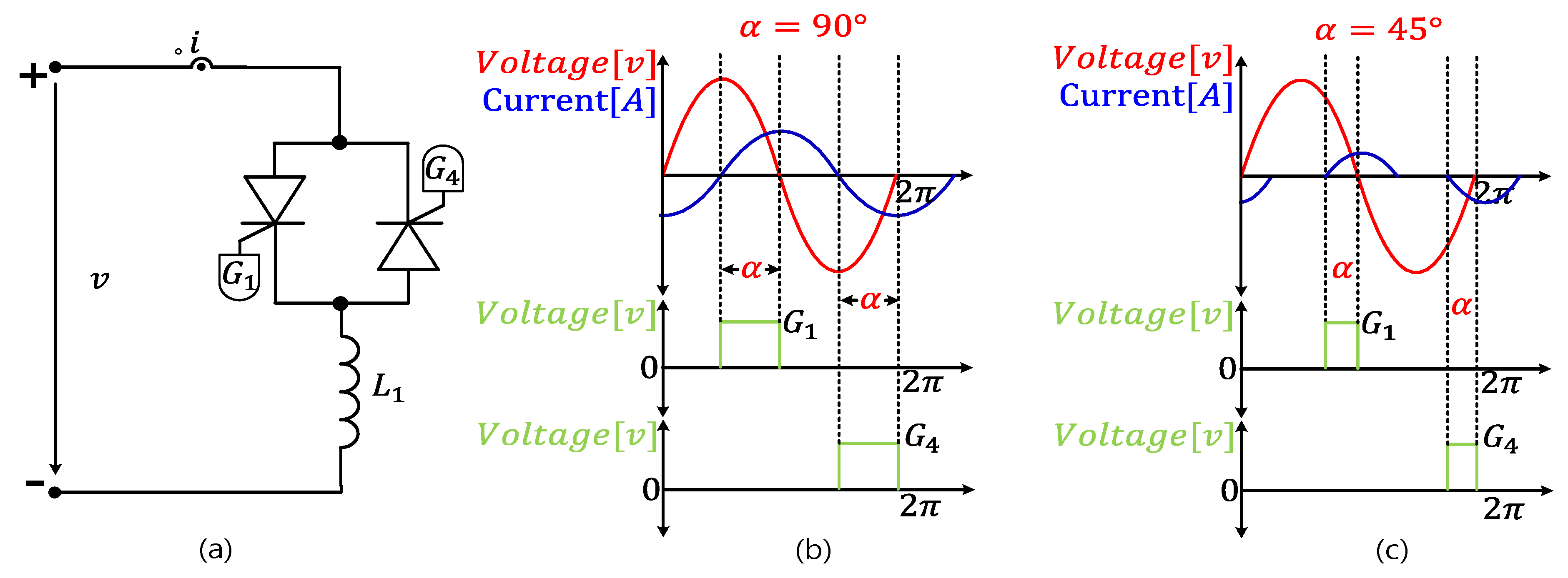
The SVC is a power quality compensation device that is widely used in large-scale industrial facilities and substations to enhance system stability and power quality. As shown in Figure 1a, an SVC generally comprises a thyristor-controlled reactor (TCR) and a thyristor-switched capacitor (TSC). In recent power systems, the increasing use of capacitive loads such as light-emitting diodes (LEDs) and electric vehicle chargers has led to reactive power conditions. To address this issue, this study considers a three-phase, four-wire SVC system employing a Y-connected TCR [15].
Figure 1b illustrates the operating principle of TCR. The Y-connected TCR consists of six bidirectional thyristors that enable bidirectional current control in each phase. The reactive power is calculated using the measured system voltages and currents, comparing it with a reference value to determine the thyristor firing angle through a proportional–integral (PI) controller. The conduction interval and magnitude of the reactor current are controlled by adjusting the firing angle, to allow continuous regulation of the lagging reactive power. This effectively compensates the leading reactive power caused by capacitive loads, improving the power factor and overall power quality [16].
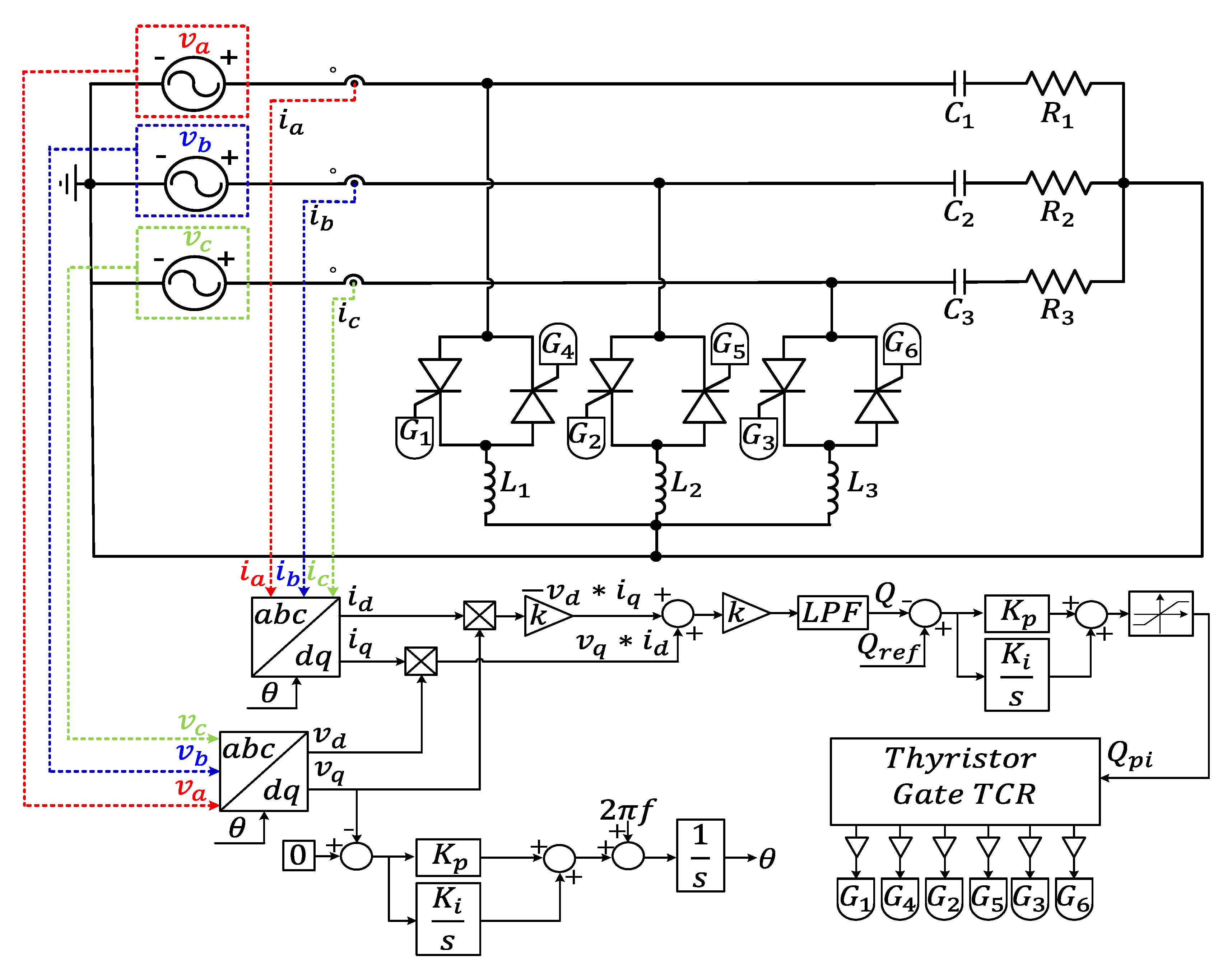
Figure 2 illustrates the conventional total reactive power control scheme for an SVC. In this method, three-phase voltages and currents are measured, and the total reactive power Q t o t a l , which is obtained by summing the reactive power of all phases, is used as the control reference based on the PQ power theory. This approach is effective under balanced operating conditions. However, when a load imbalance occurs, the reactive power errors of the individual phases can mutually be canceled. As a result, even if Q t o t a l = 0 , the phase-wise reactive power cannot be regulated to zero, leading to a phase imbalance and power quality degradation.
P Q = 3 2 · v d v q v q v d · i d i q
Q = 3 2 ( v q i d v d i q )
Q = Q a + Q b + Q c = 0
Q a ,   Q b ,   Q c 0
The conventional control scheme employs integrated phase-locked loop (PLL)-based firing control. Under grid phase variations or load fluctuations, PLL tracking errors can cause firing angle deviations, resulting in reactive power overcompensation or undercompensation, which can degrade the power factor and reduce compensation accuracy. Therefore, this paper proposes a real-time active SVC control method capable of simultaneously responding to grid phase variations and load fluctuations.

2.2. Review of the Proposed Real-Time Active SVC Control Strategy

The real-time active SVC control strategy proposed in this study is an advanced approach that complements the overall reactive power control method described in Section 2.1, enabling simultaneous compensation for both source-phase variations and load dynamics. The proposed control process is mathematically formulated in (5) to (14), where time-varying reactive power and phase angle are independently calculated and compensated on a per-phase basis [13,17,18,19,20,21].
First, the phase voltages and currents of the system are measured in real time as input signals, as expressed in (5). The measured phase voltages and currents are assumed to be sinusoidal waveforms containing phase angle and frequency components,
v x t = V m sin ω t + Φ v ,   i x t = I m sin ω t + Φ i , x a ,   b ,   c
which are processed through the active transformation control block, to extract the in-phase α and quadrature β components with a 90° phase delay, as described in (6). The extracted per-phase α β components of the voltage and current are then transformed into the d q axis components through the park transformation, as expressed in (7).
v x _ α = k ω ^ _ x s 2 + k ω ^ _ x + ω ^ 2 · v x ( s ) v x _ β = k ω ^ _ x 2 s 2 + k ω ^ _ x + ω ^ 2 · v x ( s ) i x _ α = k ω ^ _ x s 2 + k ω ^ _ x + ω ^ 2 · i x ( s ) i x _ β = k ω ^ _ x 2 s 2 + k ω ^ _ x + ω ^ 2 · i x ( s ) , x a ,   b ,   c
v x _ d v x _ q = c o s   θ x s i n   θ x s i n   θ x c o s   θ x · v x _ α v x _ β ,   i x _ d i x _ q = c o s   θ x s i n   θ x s i n   θ x c o s   θ x · i x _ α i x _ β         x a ,   b ,   c
The per-phase voltages and currents in the d q reference frame obtained through the park transformation are used to calculate the instantaneous reactive power of each phase according to (8). The calculated reactive power is then processed using a low-pass filter, as shown in (9), to eliminate the alternating current (AC) components and extract only the direct current (DC) component of the reactive power. Subsequently, the measured reactive power is subtracted from the reference reactive power Q r e f , and the resulting error is used to generate a per-phase reactive power control signal, as expressed in (11).
Q x = v x _ q · i x _ d v x _ d · i x _ q ,               x a ,   b ,   c
Q x L P F ( s ) = ω n 2 s 2 + 2 ζ ω n s + ω n 2 · Q x ( s ) ,               x a ,   b ,   c
e Q x = Q r e f Q x L P F ,               x a ,   b ,   c
Q x _ p i = K p _ p i · e Q x + K i _ p i   e Q x · d t ,               x a ,   b ,   c
The per-phase voltages measured through the active transformation control block are further processed to estimate the phase angle of each phase. The q -axis voltage component obtained from the park transformation is compared with a reference voltage of zero, and the resulting error is regulated using a PI controller. The controller output is then combined with the nominal system angular frequency of 60 Hz to generate a per-phase angular frequency. Subsequently, the phase angles synchronized with the source voltage are extracted individually through an integration process. This procedure is described in (12) and (13), where the estimated angular frequency and phase angle are utilized during both the active transformation process and per-phase phase angle generation for real-time control.
v x _ e r r = 0 v x q ,     v p i _ x = K p · v x _ e r r + K i   v x _ e r r · d t ,               x a ,   b ,   c
ω _ x = 2 π f + v p i _ x ,               θ _ x = ω _ x · d t ,               x a ,   b ,   c
α a = f Q a _ p i = π 2 + 1 Q a _ p i 2 · π 2
α b = f Q b _ p i = π 2 + 1 Q b _ p i 2 · π 2
α c = f Q c _ p i = π 2 + 1 Q c _ p i 2 · π 2
Finally, the per-phase reactive power control outputs determine the firing angles of the TCR, such that the reactive power absorption is continuously adjusted according to the magnitude of the control signals. In (14)–(16), the PI controller outputs are linearly mapped to the thyristor firing angles around the nominal value of π/2, and the resulting firing-angle commands modify the conduction interval of the TCR to enable continuous per-phase reactive power regulation. The per-phase firing angles α a , α b , and α c , along with the corresponding phase angles θ a , θ b , and θ c , determine the thyristor conduction intervals for the generated gate signals.
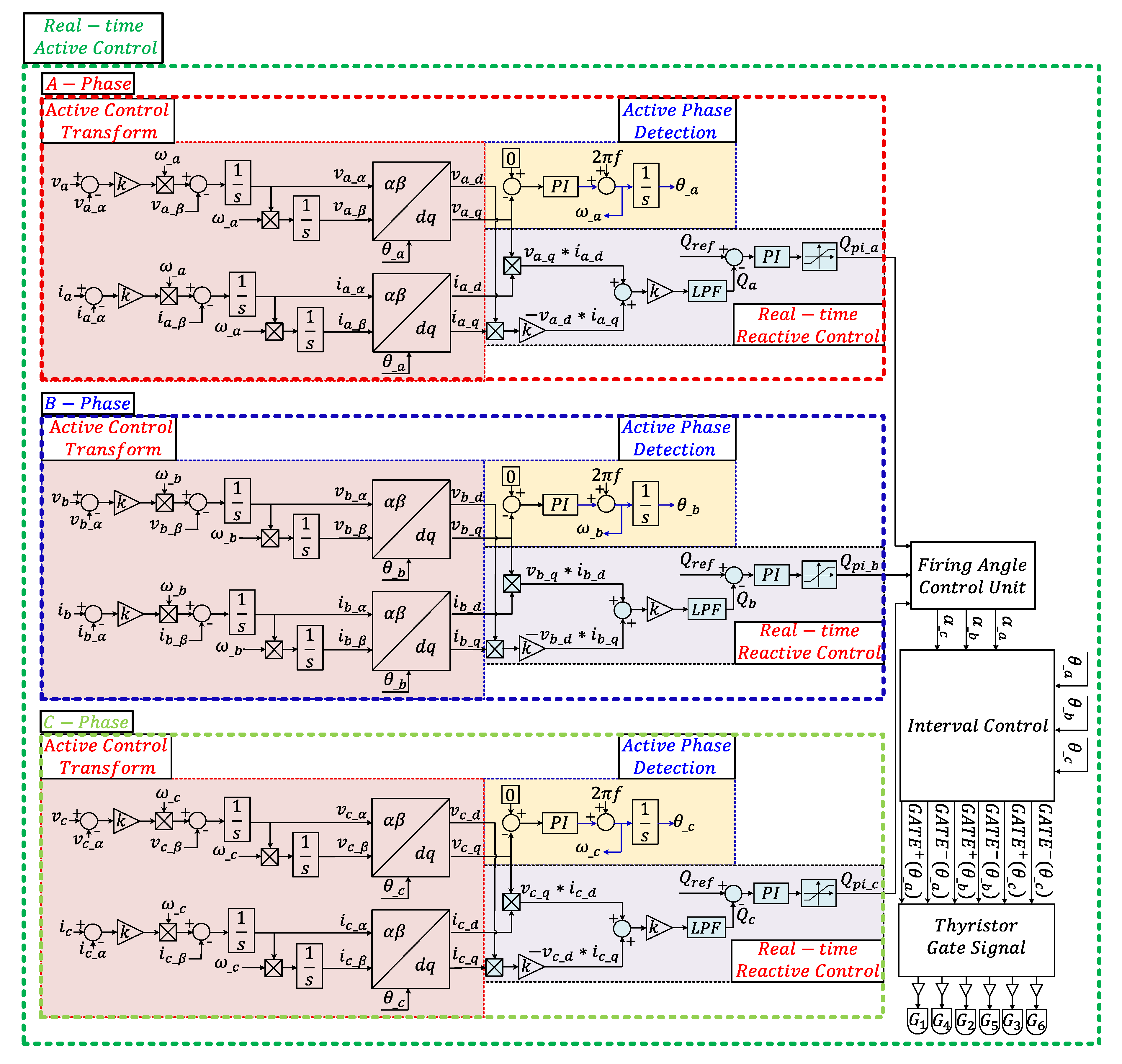
Figure 3 illustrates the proposed real-time active control strategy that simultaneously compensates for source-phase variations and load imbalance. In the presence of source phase fluctuations, the firing angles are calculated and compensated based on the individually estimated phase angles, whereas the reactive power is independently calculated and supplied on a per-phase basis. The effectiveness of the proposed control strategy was verified through PSIM-based simulations, hardware implementation, and experimental validation.
From a stability perspective, the proposed method is based on a closed-loop feedback structure in which the per-phase reactive power error is regulated by a PI controller. Because each phase is independently controlled in the d–q reference frame, cross-coupling effects under unbalanced conditions are structurally reduced. The low-pass filter ensures bounded control inputs by suppressing high-frequency components. In addition, the synchronous reference frame-based phase estimation loop drives the q-axis voltage error toward zero under nominal conditions, leading to bounded phase tracking error. Therefore, the overall control system maintains stable and robust compensation performance under practical grid phase variations and load fluctuations.

3. Simulation and Result Analysis of the Proposed Real-Time Active SVC Control Strategy

3.1. Simulation Circuit Configuration and Parameters Used in the Study

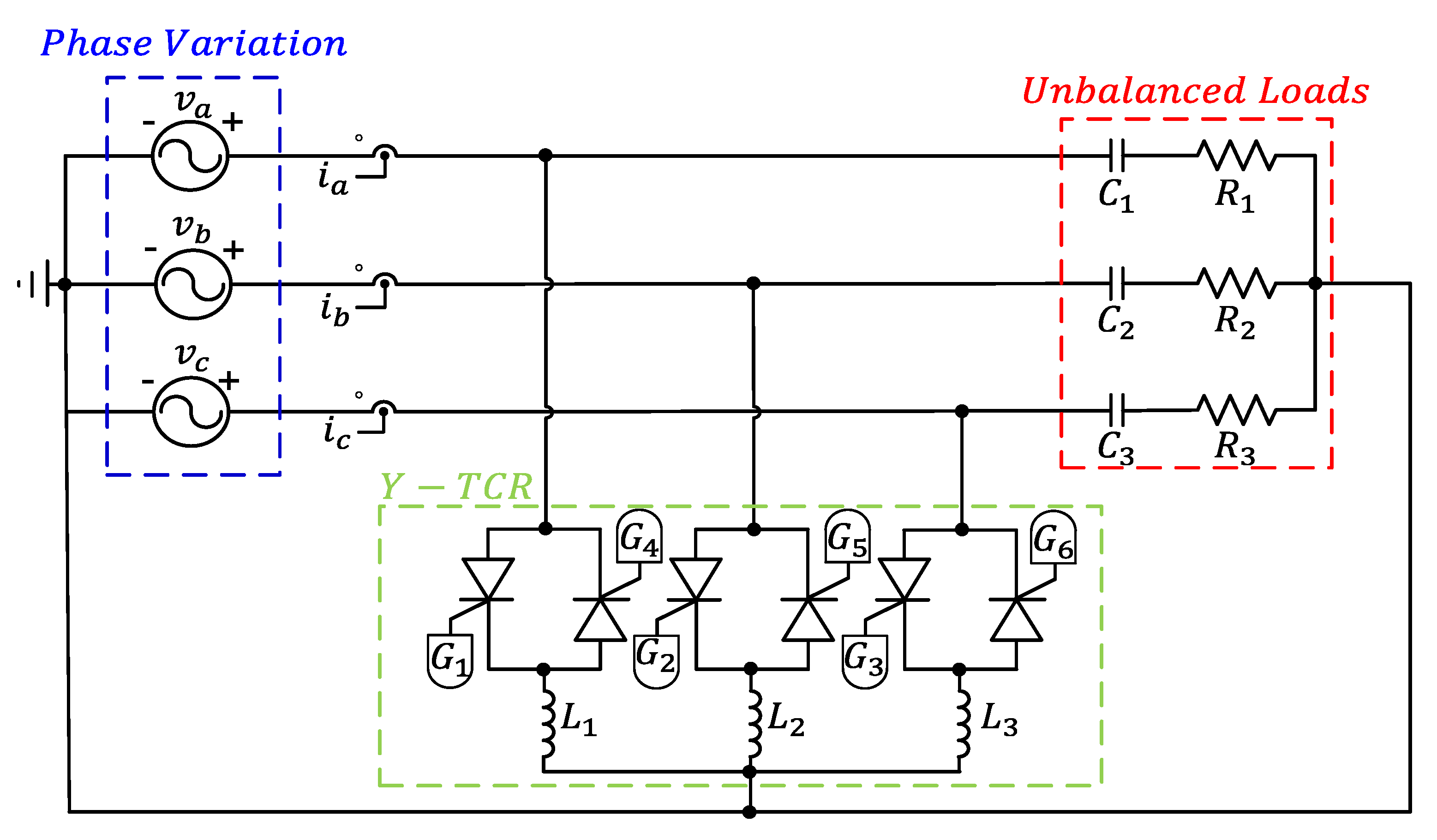
Section 3 presented the PSIM simulations conducted to verify the proposed real-time active control strategy. As shown in Figure 4, a Y-connected TCR-based SVC system was employed, and the simulations were performed by varying the phase angle and load of the C-phase under unbalanced load conditions. The simulation parameters used in this study are summarized in Table 1.
Because the proposed system operates at a low voltage, variations in the reactive power were not clearly observed under small phase deviations. Therefore, to ensure a clear evaluation of the control performance, the phase angle of the C-phase was intentionally varied by 10°, 20°, and 30° in the simulation studies.

3.2. Simulation Analysis of Different Control Strategies Under Unbalanced Load Conditions

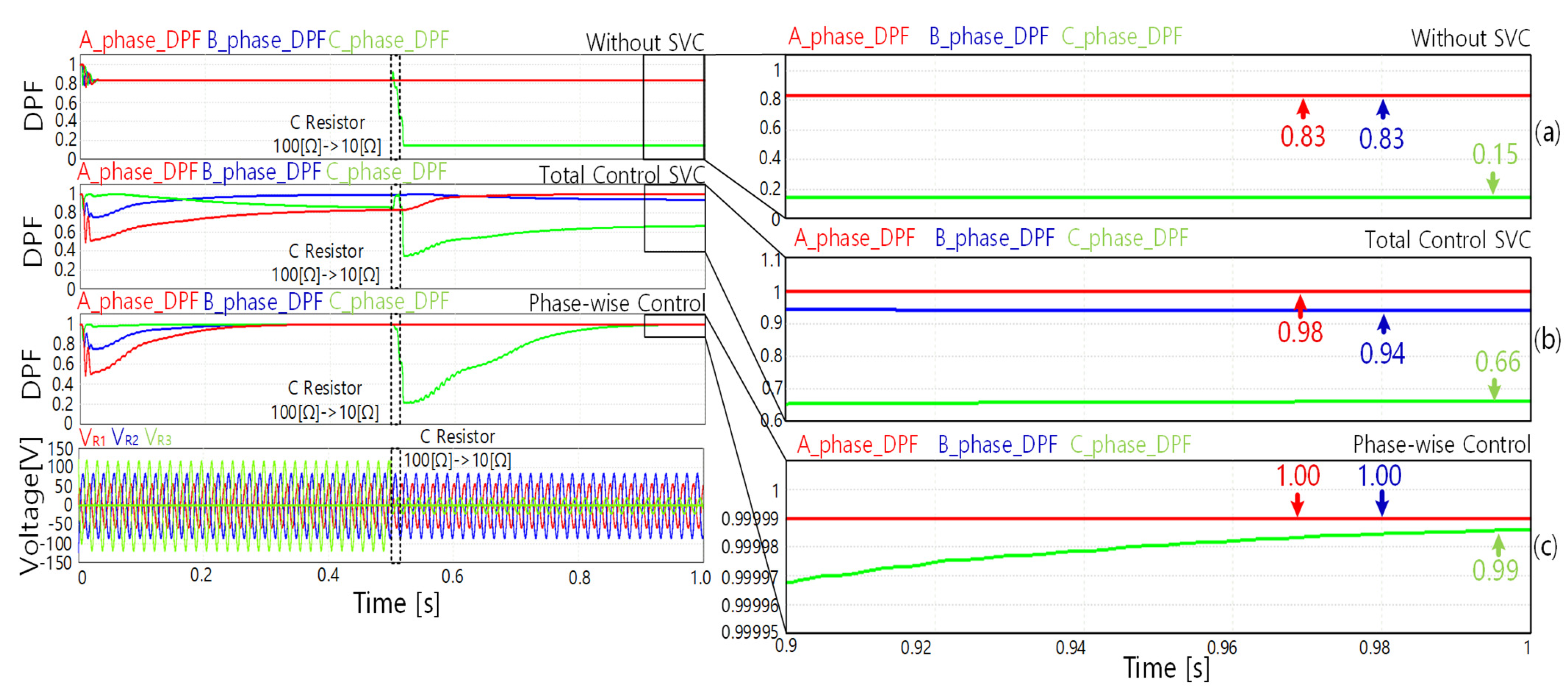
Figure 5 compares the simulation results for three cases: without the SVC, the conventional total reactive power control method, and the phase-wise control method. Under unbalanced load conditions, without the SVC, the fundamental power factors of each phase decreased significantly to 0.83, 0.83, and 0.15, respectively. When the total reactive power control method was applied, the fundamental power factors improved to 0.98, 0.94, and 0.66; however, they did not reach the target fundamental power factor of 1.00. In contrast, with the phase-wise control method, all three phases achieved a fundamental power factor of 1.00, even when the C-phase load was changed to 10 Ω at 0.5 s.
The simulation results of the fundamental power factor under unbalanced load conditions for the different control strategies are listed in Table 2. With the total reactive power control method, a target fundamental power factor of 1.00 was achieved even under load imbalance. However, because the firing angle is determined based on the phase information extracted through a centralized PLL, phase-angle variations in the supply voltage or an input voltage imbalance can introduce phase-detection errors. As a result, the reactive power may be overcompensated or undercompensated, leading to degradation of the power factor and overall power quality. To address these limitations, this paper proposes a real-time active control strategy, the effectiveness of which is verified through PSIM-based simulation studies.

3.3. Simulation Results and Analysis of the Proposed Real-Time Active SVC Control Strategy

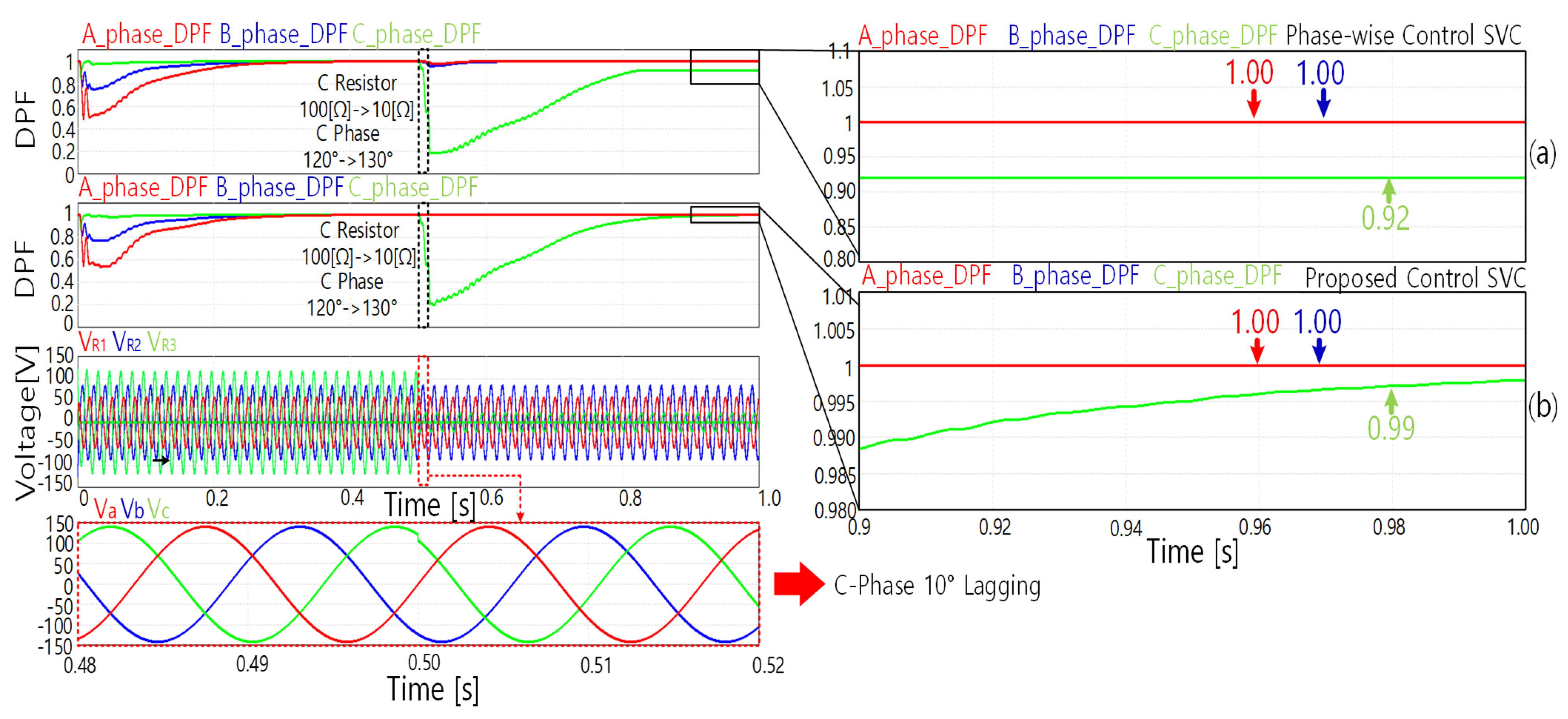
Figure 6 presents a simulation scenario that starts under unbalanced load conditions, with A-, B-, and C-phase loads of 30, 50, and 100 Ω, respectively. At 0.5 s, the phase angle of the C-phase is delayed by 10°, and simultaneously, the C-phase load is changed to 10 Ω. Under these conditions, when the phase-wise control method is applied, the fundamental power factor of the C-phase decreases to 0.92 due to supply phase variation and load change. In contrast, when the proposed control method is employed, the fundamental power factor of the C-phase improves to 0.99 under the same conditions, demonstrating superior compensation performance against phase and load variations.
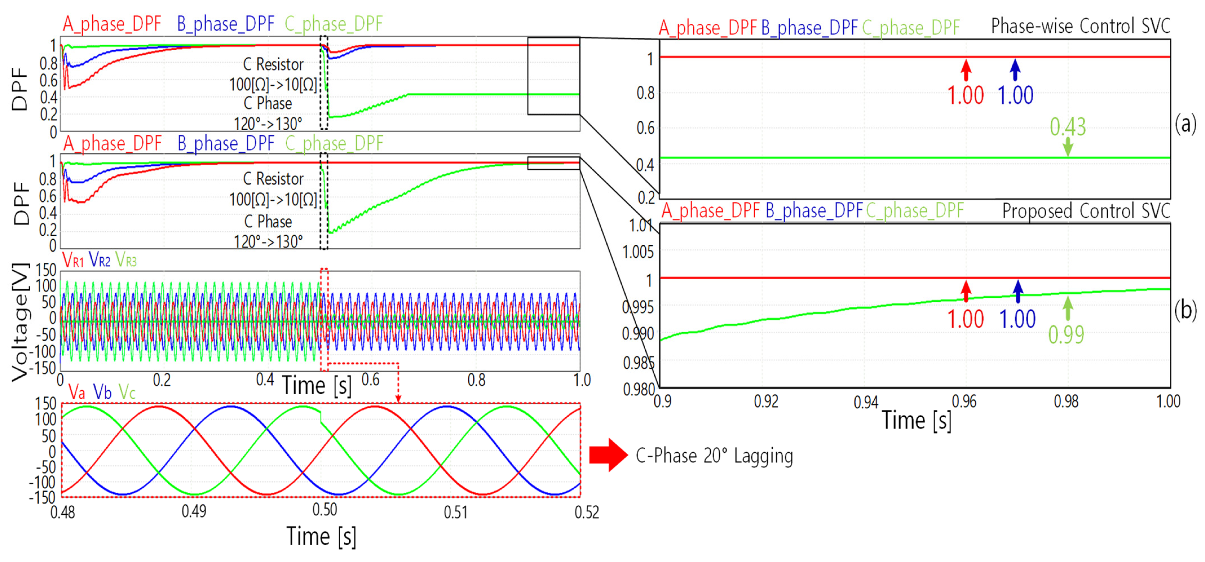
Figure 7 shows the variation in the fundamental power factor when the C-phase angle is delayed by 20° and the C-phase load is simultaneously changed to 10 Ω. Under these conditions, when the phase-wise control method is applied, the fundamental power factor of the C-phase decreases to 0.43 due to phase delay and load variation. In contrast, when the proposed control method is applied, the fundamental power factor of the C-phase is maintained at 0.99 under the same conditions.
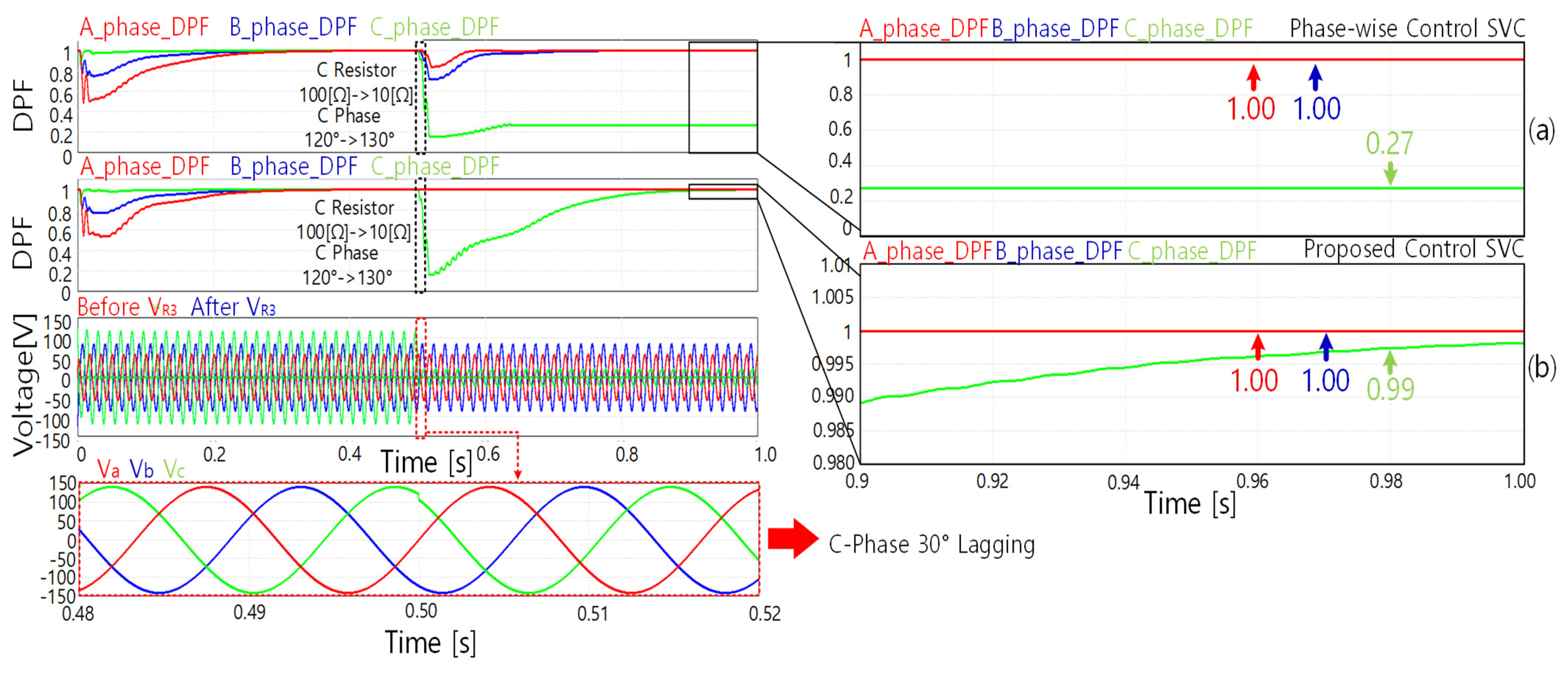
Figure 8 shows the variation in the fundamental power factor when the C-phase angle is delayed by 30°. Under this condition, when the phase-wise control method is applied, the fundamental power factor of the C-phase decreases to 0.27 due to the large phase delay. In contrast, when the proposed control method is applied, the fundamental power factor of the C-phase is maintained at 0.99 under the same conditions.
Table 3 compares the fundamental power factors of phases A, B, and C obtained using phase-wise control and the proposed real-time active control methods, as the C-phase supply angle is varied by 10°, 20°, and 30° and the C-phase load is changed from 100 to 10 Ω. When the phase-wise control method is applied, the fundamental power factor can be maintained at 1.00 under unbalanced load conditions; however, when the supply phase varies, the firing angle calculation errors lead to overcompensation or undercompensation of reactive power. In contrast, the proposed real-time active control method can simultaneously respond to supply phase variations and load changes, maintaining the target fundamental power factor (1.00) under all tested conditions. To quantitatively evaluate the degree of phase imbalance, the phase power-factor deviation index ΔDPF is defined in (17) as the difference between the maximum and minimum DPF values among the three phases.
D P F = m a x D P F A ,   D P F B ,   D P F C m i n ( D P F A ,   D P F B ,   D P F C )
As summarized in Table 3, the conventional phase-wise control exhibits a significant increase in ΔDPF as the C-phase delay increases, reaching 0.73 at a 30° delay. In contrast, the proposed real-time active control method maintains ΔDPF at approximately 0.01 under all tested conditions, thereby demonstrating superior phase balancing capability.
Table 4 presents a quantitative comparison of the simulated phase reactive powers under increasing C-phase delay conditions with a load step from 100 Ω to 10 Ω. For the conventional phase-wise control, both the worst-phase residual reactive power Q m a x and the phase reactive power imbalance index Q increase significantly as the C-phase delay increases. Specifically, Q m a x rises from 0.029 kVAR at 10° to 0.078 kVAR at 30°, while Q increases from 0.028 kVAR to 0.077 kVAR. This indicates that the conventional control method fails to properly compensate for reactive power under severe phase delay conditions. In contrast, the proposed real-time active control method maintains Q m a x 0.002 kVAR and Q   0.001 kVAR across all tested delay conditions, demonstrating strong robustness against increasing phase disturbances in the simulation results. These characteristics will be further verified through digital signal processing (DSP)-based hardware experiments.

4. Hardware Experiments and Result Analysis of the Proposed Real-Time Active SVC Control Strategy

4.1. Design and Implementation of the SVC for Hardware Experiments

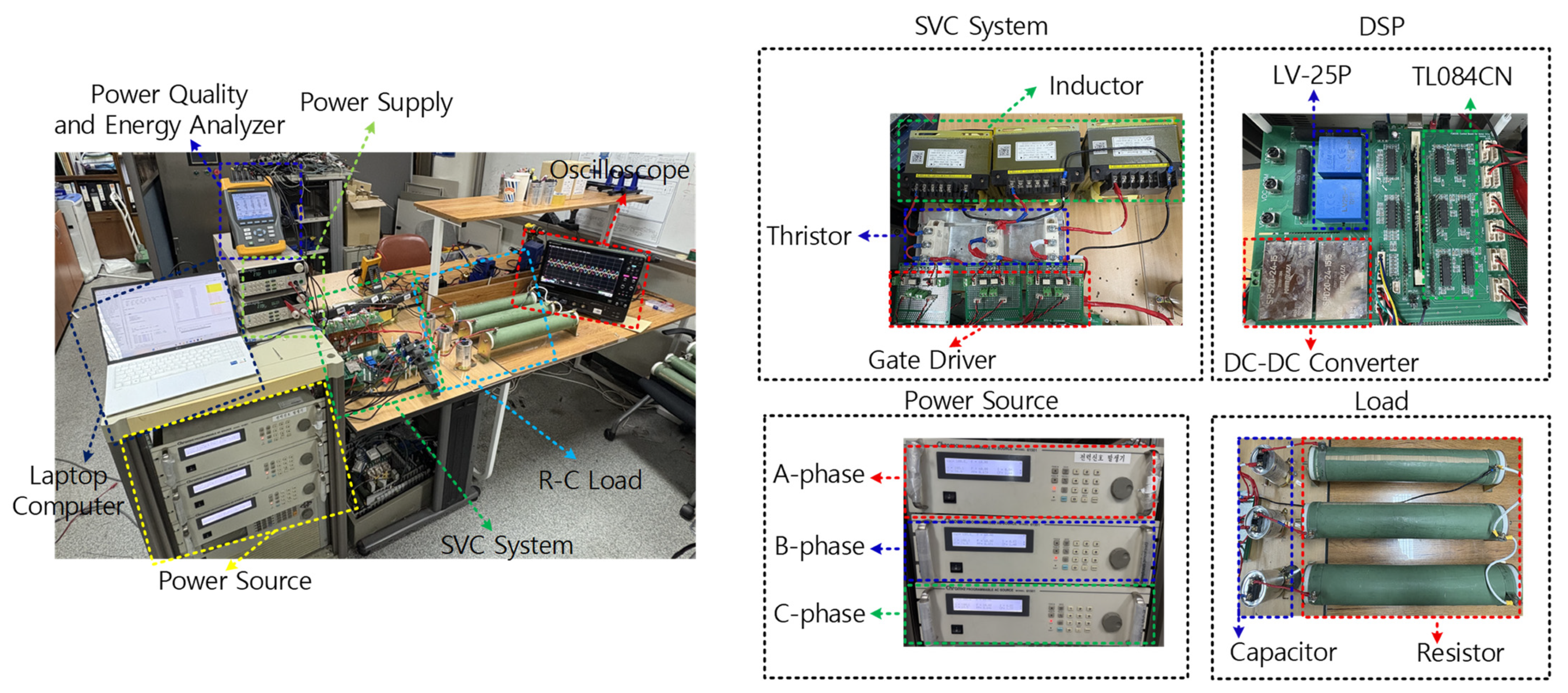
In Section 4, the hardware experiments conducted to validate the PSIM simulation results are described. Hardware experiments were performed based on the same circuit configuration and parameters used in the simulation studies, and a TMS320F28335 MCU was employed for gate signal control. The proposed real-time active control strategy was implemented in the Code Composer Studio (CCS) environment and executed in real time. The key parameters used in the hardware experimental setup are summarized in Table 5. The overall hardware experimental setup and main components of the SVC system are shown in Figure 9.

4.2. Experimental Results of Control Strategies Under Load Imbalance

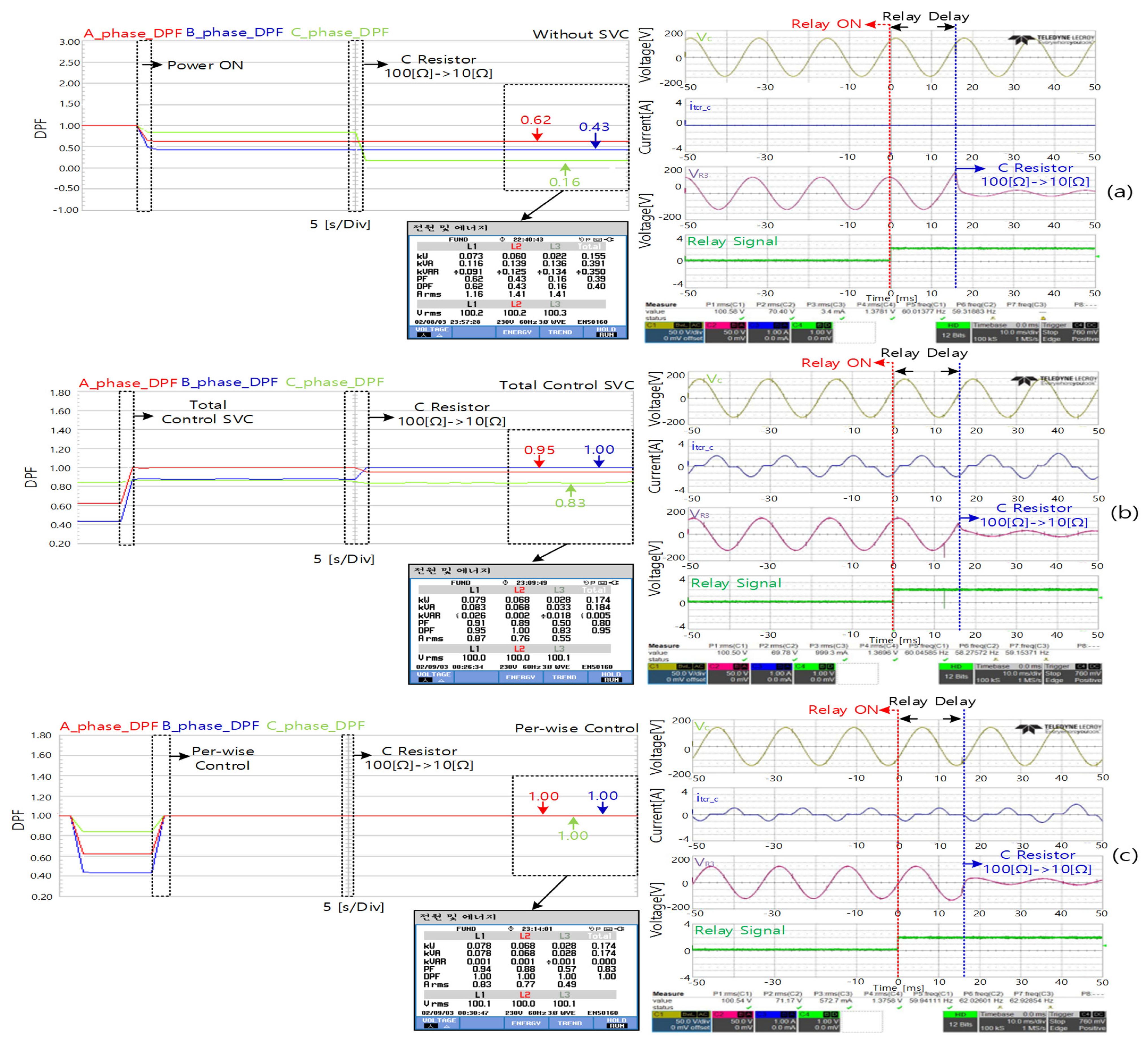
This section evaluates the compensation performance of the SVC under unbalanced load conditions, in which the load of a specific phase was subjected to sudden variations. The experimental results were comparatively analyzed for three cases: without an SVC application, with a total reactive power control scheme, and with a phase-wise reactive power control scheme. The experiment was conducted by abruptly changing the phase-C load resistance from 100 to 10 Ω using a relay after applying input power. The relay used in the experiment had an inherent delay of 13.7 ms. During the experiment, the phase-C input voltage, phase-C TCR current, phase-C load voltage, and relay-switching signal were measured using an oscilloscope. To quantitatively analyze the power factor characteristics of the system during load variation, a Fluke 434 power quality analyzer was used to measure three-phase displacement power factor (DPF) waveforms.
Figure 10a shows the experimental results without the SVC application. Under unbalanced load conditions, the fundamental power factor was significantly degraded, and when the phase-C load was varied abruptly, the fundamental power factor dropped sharply to approximately 0.16. Figure 10b shows the results obtained using the total reactive power control scheme. Compared with the case without the SVC, both the power factor and overall power quality improved; however, the system failed to reach the target fundamental power factor of 1.00. In contrast, Figure 10c shows the results obtained using the phase-wise reactive power control scheme. The target fundamental power factor of 1.00 was stably maintained not only under the initial load imbalance but also during abrupt load variations in phase C. The experimental results of the fundamental power factor under unbalanced load conditions are summarized in Table 6.

4.3. Experimental Verification and Result Analysis of the Proposed Real-Time Active SVC Control Strategy

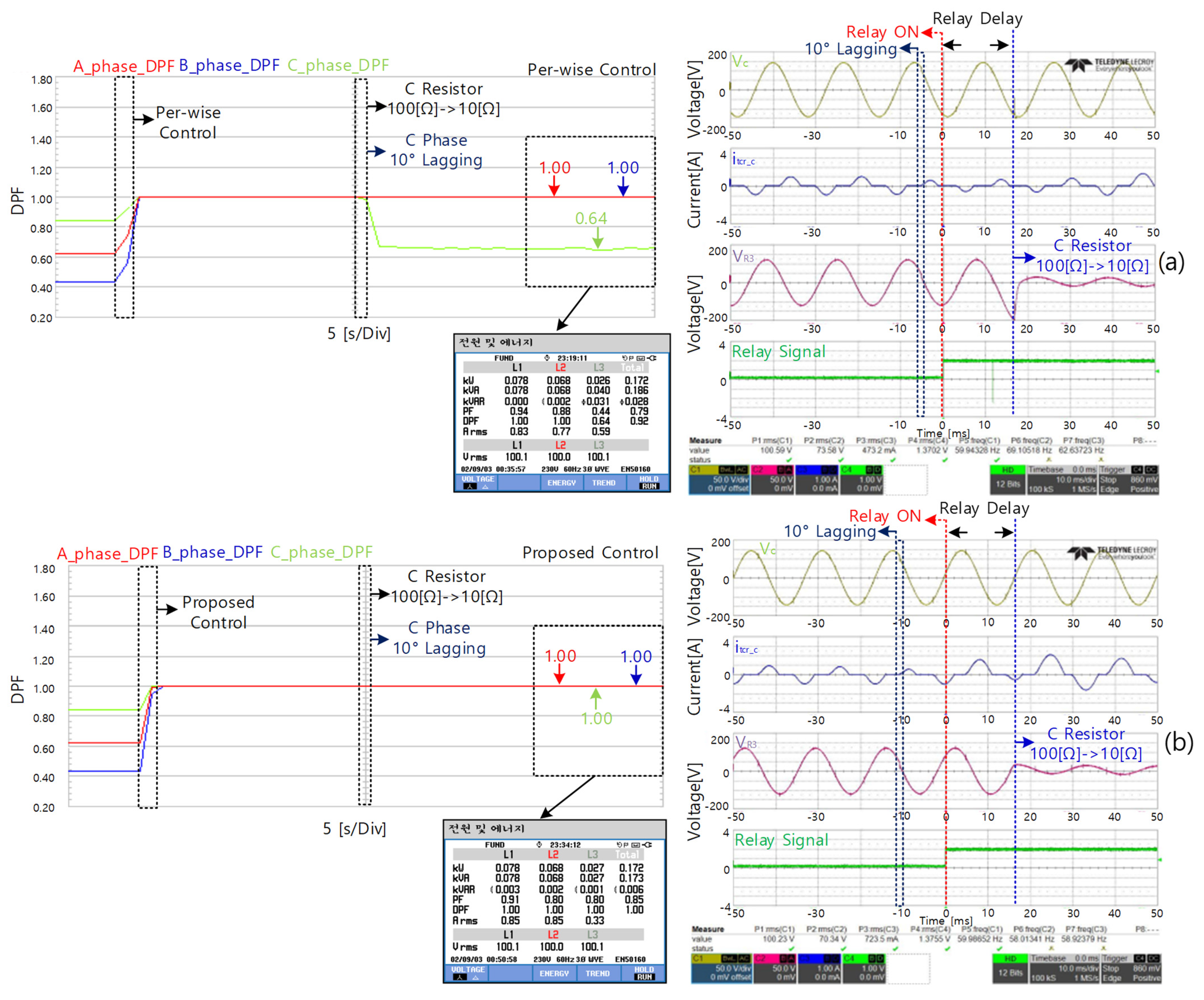
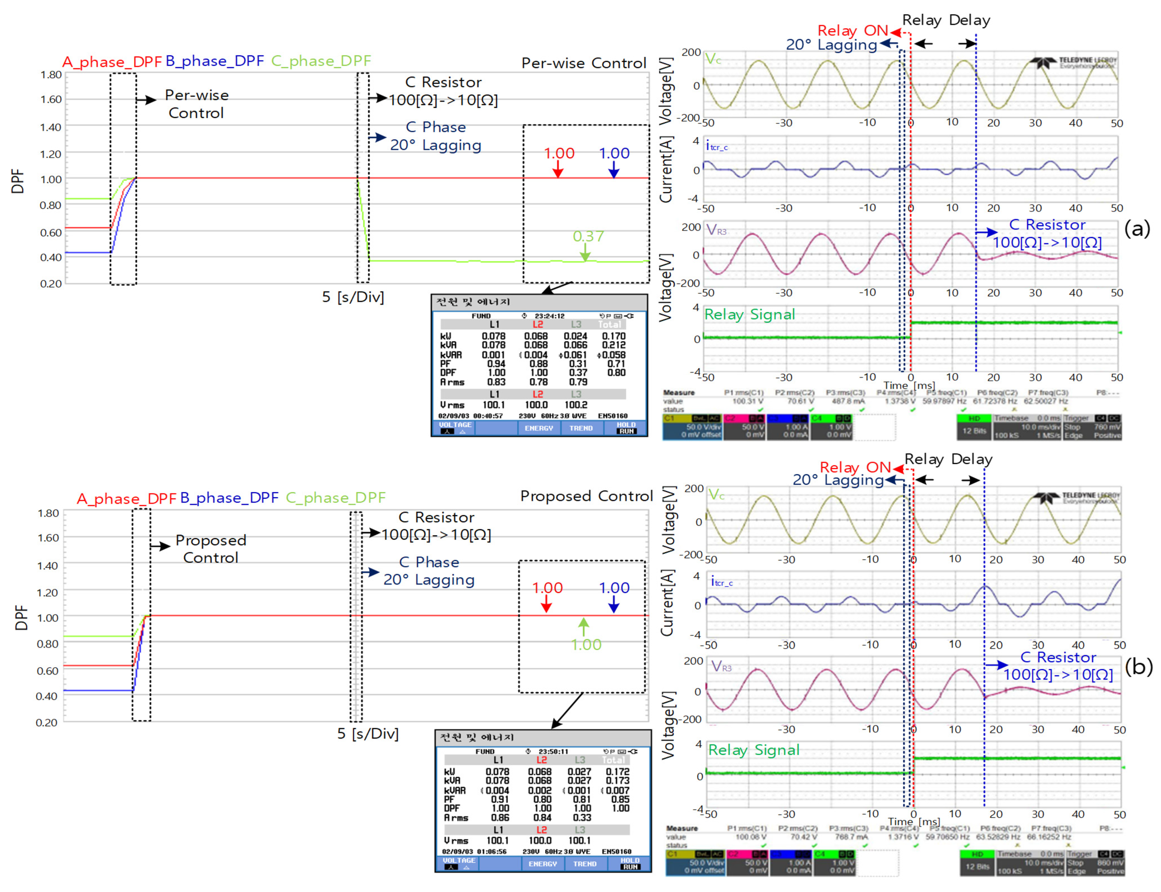
This section investigates the experimental conditions under which a phase-angle disturbance under load imbalance triggered the relay operation, resulting in an abrupt load change in phase C. A phase disturbance was applied at 10°, 20°, and 30°, with the source phase variation and load change occurring simultaneously. Under these conditions, the conventional phase-wise reactive power and the proposed real-time active control schemes were compared in terms of compensation performance.
Figure 11 presents the experimental hardware results comparing the phase-wise and proposed control schemes under a 10° phase-angle disturbance in phase C with a simultaneous load change from 100 to 10 Ω. Under the conventional phase-wise control scheme, the DPF of phase C was reduced to approximately 0.64, whereas with the proposed control scheme, the three-phase fundamental power factor remained at 1.00 despite the disturbance.
Figure 12 shows the experimental results obtained when the source phase angle of phase C was changed by 20° while changing the load from 100 to 10 Ω. Under the conventional phase-wise control scheme, the DPF of phase C decreased to approximately 0.37, whereas under the proposed control scheme, the fundamental power factor was maintained at 1.00.
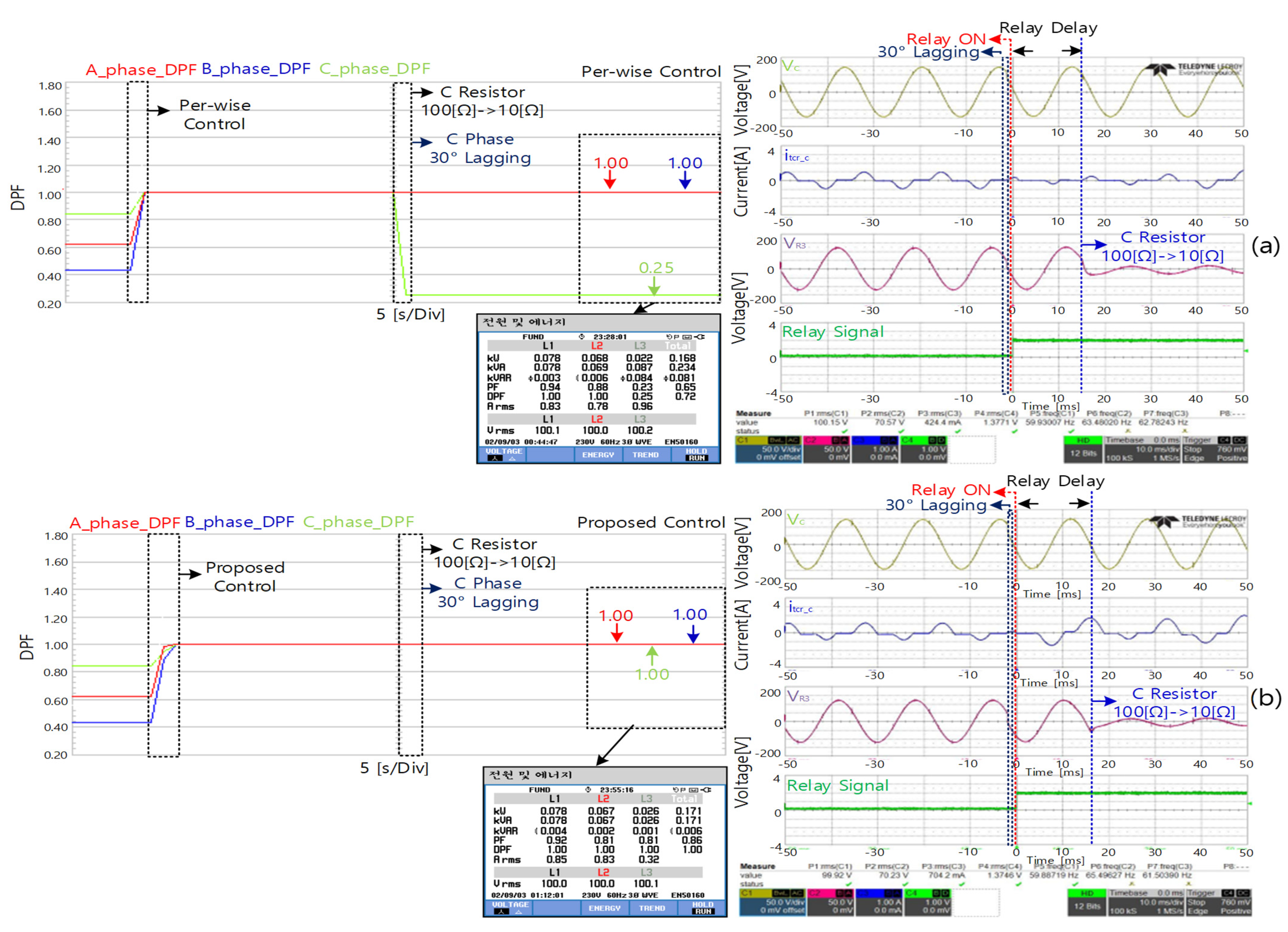
Figure 13 presents the experimental results under a more severe condition, where the source phase angle of phase C was changed by 30° along with the same load change from 100 to 10 Ω. In this case, the DPF of phase C further decreased to approximately 0.25 under the phase-wise control scheme, whereas the proposed control scheme maintained a three-phase DPF of 1.00.
Table 7 presents the fundamental power factor results of the phase-wise and proposed real-time active control schemes when the source phase angle of phase C was delayed by 10°, 20°, and 30°, with the phase-C load changing to 10 Ω. Although the phase-wise control scheme responds to load imbalance, its performance degrades under source phase disturbances because of firing angle errors that reduce the power factor and power quality.
Table 8 quantitatively compares the measured phase reactive powers under different C-phase delay conditions with a load step from 100 Ω to 10 Ω. For the conventional phase-wise control, both Q m a x and Q increased significantly as the C-phase delay increased (from 0.031 to 0.084 kVAR and from 0.031 to 0.081 kVAR, respectively), indicating insufficient compensation and enlarged phase imbalance. In contrast, the proposed real-time active control method maintained a much smaller Q m a x ( 0.004 kVAR) and Q ( 0.003 kVAR) for all tested delays, demonstrating improved reactive power balancing capability under simultaneous phase disturbance and load variation. In contrast, the proposed control scheme maintained a three-phase fundamental power factor of 1.00 even under simultaneous source-phase disturbances and load imbalance by independently compensating for the reactive power of each phase.

5. Conclusions

A real-time active control scheme was proposed for an SVC capable of effectively responding to simultaneous supply voltage phase variations and load imbalances. Unlike conventional SVC control methods, which are primarily based on total reactive power compensation under balanced conditions, the proposed strategy independently calculates the reactive power of each phase and individually controls the firing angles in a three-phase four-wire system, thereby enhancing the overall power quality.
The performance of the proposed control scheme was first validated through PSIM simulations under artificially generated load imbalances and supply voltage phase variation conditions. The simulation results showed that the conventional total reactive power control method experienced a significant degradation in the fundamental power factor for specific phases under load imbalance. Although the phase-wise control method maintained a unity fundamental power factor under load imbalance, its performance deteriorated when supply voltage phase variations occurred. In contrast, the proposed real-time active control scheme consistently maintained a fundamental power factor of 1.00 in all three phases, even under simultaneous load imbalance and supply voltage phase variation.
Additionally, DSP-based hardware experiments were conducted to verify the effectiveness of the proposed scheme in a practical system. The experimental results confirmed that although the phase-wise control method improved the power factor under load imbalance, it still suffered from power quality degradation under supply voltage phase variation. In comparison, the proposed control scheme stably maintained the three-phase fundamental power factor at unity under all tested conditions.
These results demonstrate that the proposed real-time active SVC control scheme achieves comprehensive power quality improvement by simultaneously considering the load imbalance and supply condition variations. Compared with conventional SVC control approaches, the proposed method offers superior robustness and is applicable in complex power system environments, including industrial power systems, renewable energy-integrated networks, and systems with large-scale power electronic loads. Consequently, the proposed control scheme is expected to significantly contribute to the development of reliable and high-quality power systems. However, several limitations should be acknowledged. The proposed method was validated on a laboratory-scale system, and its performance under high-voltage or large-capacity industrial grid conditions requires further investigation. In practical grid-connected environments, additional considerations such as communication delays, protection coordination, electromagnetic interference, and large-scale parameter variations must be addressed. Therefore, future work will focus on scalability analysis and validation in high-power and industrial-level power systems.

Author Contributions

Conceptualization, J.L.; methodology, J.L.; software, J.L.; validation, J.L.; formal analysis, J.L.; writing—original draft preparation, J.L.; writing—review and editing, J.L. and J.S.; supervision, J.S. All authors have read and agreed to the published version of the manuscript.

Funding

This work was partly supported by the Institute of Information & Communication Technology Planning & Evaluation (IITP)—Information Technology Research Center (ITRC) grant funded by the Korea government (Ministry of Science and ICT) (IITP-2025-RS-2023-00259004) and partly supported by the Korea Institute of Energy Technology Evaluation and Planning (KETEP) grant funded by the Korea government (MCEE) (No. 20214000000060, Department of Next Generation Energy System Convergence based on Techno-Economics-STEP).

Data Availability Statement

The original contributions presented in this study are included in the article. Further inquiries can be directed to the corresponding author(s).

Acknowledgments

During the preparation of this manuscript, we used ChatGPT (OpenAI, GPT-5.3) for language editing and clarity improvement. The authors reviewed and edited the manuscript and take full responsibility for its content.

Conflicts of Interest

The authors declare no conflicts of interest.

References

  1. Yang, Y.; Wen, Y.; Zhang, Z.; Dong, Y.; Shen, C.; Liu, Y. Toward 100% renewable power grids: A review. IEEE Access 2025, 13, 69690–69704. [Google Scholar] [CrossRef] [Scilit]
  2. Babu, R.M.; Alam, M.S.; Islam, A.; Islam, K.M. Toward sustainable and clean energy futures: A techno-economic review of solar PV systems, challenges, and opportunities. IEEE Access 2025, 13, 169720–169757. [Google Scholar] [CrossRef] [Scilit]
  3. Zhu, H.; Li, H.; Liu, G.; Ge, Y.; Shi, J.; Li, H.; Zhang, N. Energy storage in high variable renewable energy penetration power systems: Technologies and applications. CSEE J. Power Energy Syst. 2023, 9, 2099–2108. [Google Scholar] [CrossRef] [Scilit]
  4. Ali, J.S.; Qiblawey, Y.; Alassi, A.; Massoud, A.M.; Muyeen, S.M.; Abu-Rub, H. Power system stability with high penetration of renewable energy sources: Challenges, assessment, and mitigation strategies. IEEE Access 2025, 13, 39912–39934. [Google Scholar] [CrossRef] [Scilit]
  5. Saleem, M.I.; Saha, S.; Roy, T.K. Inertia sensitivity analysis of power grids with high penetration of renewable energy sources. IEEE Trans. Ind. Appl. 2025, 61, 5362–5380. [Google Scholar] [CrossRef] [Scilit]
  6. Saleh, S.A.; Wo, J.; St-Onge, X.F.; Castillo-Guerra, E. A new approach for estimating frequency variations due to smart grid functions. IEEE Trans. Ind. Appl. 2020, 56, 2292–2303. [Google Scholar] [CrossRef] [Scilit]
  7. Hou, Q.; Du, E.; Zhang, N.; Kang, C. Impact of high renewable penetration on the power system operation mode: A data-driven approach. IEEE Trans. Power Syst. 2020, 35, 731–741. [Google Scholar] [CrossRef] [Scilit]
  8. Czarnecki, L.S. Instantaneous reactive power p–q theory and power properties of three-phase systems. IEEE Trans. Power Deliv. 2006, 21, 362–367. [Google Scholar] [CrossRef] [Scilit]
  9. Rajashekaraiah, K.; Iurlaro, C.; Bruno, S.; De Carne, G. Modelling of 3-phase p–q theory-based dynamic load for real-time simulation. IEEE Open Access J. Power Energy 2023, 10, 654–664. [Google Scholar] [CrossRef] [Scilit]
  10. Li, Y.; Ding, Q.; Li, S.; Valtchev, S. Optimal controller design for non-affine nonlinear power systems with static VAR compensators for hybrid UAVs. Tsinghua Sci. Technol. 2022, 27, 196–206. [Google Scholar] [CrossRef] [Scilit]
  11. Gong, C.; Sou, W.-K.; Lam, C.-S. H∞ optimal control design of static VAR compensator coupling hybrid active power filter based on harmonic state-space modeling. CPSS Trans. Power Electron. Appl. 2021, 6, 227–234. [Google Scholar] [CrossRef] [Scilit]
  12. Mukhopadhyay, S.; Maiti, D.; Banerji, A.; Biswas, S.K.; Deb, N.K. A new harmonic reduced three-phase thyristor-controlled reactor for static VAR compensators. IEEE Trans. Ind. Electron. 2017, 64, 6898–6907. [Google Scholar] [CrossRef] [Scilit]
  13. Sun, L.-Y.; Tong, S.; Liu, Y. Adaptive backstepping sliding mode H∞ control of static VAR compensator. IEEE Trans. Control Syst. Technol. 2011, 19, 1178–1185. [Google Scholar] [CrossRef] [Scilit]
  14. Fang, D.Z.; Yang, X.; Chung, T.S.; Wong, K.P. Adaptive fuzzy-logic SVC damping controller using strategy of oscillation energy descent. IEEE Trans. Power Syst. 2004, 19, 1414–1421. [Google Scholar] [CrossRef] [Scilit]
  15. Das, S.; Chatterjee, D.; Goswami, S.K. A reactive power compensation scheme for unbalanced four-wire system using virtual Y-TCR model. IEEE Trans. Ind. Electron. 2018, 65, 3210–3219. [Google Scholar] [CrossRef] [Scilit]
  16. Mukhopadhyay, S.; Maiti, D.; Biswas, S.K.; Banerji, A.; Deb, N.K. A wide-range TCR with low-current THD by optimized combination of coupled reactors and thyristor switching and control. IEEE Trans. Ind. Electron. 2018, 65, 3657–3665. [Google Scholar] [CrossRef] [Scilit]
  17. Xiao, F.; Dong, L.; Li, L.; Liao, X. A frequency-fixed SOGI-based PLL for single-phase grid-connected converters. IEEE Trans. Power Electron. 2017, 32, 1713–1719. [Google Scholar] [CrossRef] [Scilit]
  18. Prakash, S.; Singh, J.K.; Behera, R.K.; Mondal, A. A type-3 modified SOGI-PLL with grid disturbance rejection capability for single-phase grid-tied converters. IEEE Trans. Ind. Appl. 2021, 57, 4242–4252. [Google Scholar] [CrossRef] [Scilit]
  19. Zhou, Y.; Zang, T.; Zhou, B.; Hu, H.; Chen, S.; Luo, H. Impacts of dynamic frequency feedback loop in SOGI-PLL on low-frequency oscillation in an electric railway system. IEEE Trans. Transp. Electrific. 2023, 9, 4080–4093. [Google Scholar] [CrossRef] [Scilit]
  20. Guo, L.; Ye, Q.; Jin, N.; Liu, Z.; Wu, Z. Sliding-mode observer-based grid voltage-observation method with frequency-fixed dual SOGI and cross-compensated phase-locked loop. Chin. J. Electr. Eng. 2024, 10, 37–49. [Google Scholar] [CrossRef] [Scilit]
  21. Mohamadian, S.; Pairo, H.; Ghasemian, A. A straightforward quadrature signal generator for single-phase SOGI-PLL with low susceptibility to grid harmonics. IEEE Trans. Ind. Electron. 2022, 69, 6997–7007. [Google Scholar] [CrossRef] [Scilit]
Figure 1. Structure and operating principle of the SVC system: (a) Basic configuration of SVC. Operating principle of TCR at firing angles of (b) 90°and (c) 45°.
Energies 19 01313 g001
Figure 2. Block diagram of conventional total reactive power control for SVC.
Energies 19 01313 g002
Figure 3. Block diagram of the proposed real-time active control method for SVC.
Energies 19 01313 g003
Figure 4. Three-phase four-wire SVC system with Y-connected TCR.
Energies 19 01313 g004
Figure 5. Comparison of displacement power factor (DPF) waveforms under load imbalance for different control strategies: (a) without SVC; (b) SVC with total reactive power control; (c) SVC with phase-wise reactive power control.
Energies 19 01313 g005
Figure 6. Comparison of fundamental power factor waveforms under C-phase 10° delay and load imbalance: (a) Phase-wise control SVC. (b) Proposed control SVC.
Energies 19 01313 g006
Figure 7. Comparison of fundamental power factor waveforms under C-phase 20° delay and load imbalance: (a) Phase-wise control SVC. (b) Proposed control SVC.
Energies 19 01313 g007
Figure 8. Comparison of fundamental power factor waveforms under C-phase delay of 30° and load imbalance: (a) Phase-wise control SVC. (b) Proposed control SVC.
Energies 19 01313 g008
Figure 9. Hardware experimental setup and components.
Energies 19 01313 g009
Figure 10. Fundamental power factor waveforms under load imbalance for different control strategies: (a) Without SVC. (b) Total control SVC. (c) Phase-wise control.
Energies 19 01313 g010
Figure 11. Fundamental power factor waveforms under a 10° C-phase delay and a 10 Ω C-phase load change: (a) Phase-wise control. (b) Real-time active control.
Energies 19 01313 g011
Figure 12. Fundamental power factor waveforms under a 20° C-phase delay and a 10 Ω C-phase load change: (a) Phase-wise control. (b) Real-time active control.
Energies 19 01313 g012
Figure 13. Fundamental power factor waveforms under a 30° C-phase delay and a 10 Ω C-phase load change: (a) Phase-wise control. (b) Real-time active control.
Energies 19 01313 g013
Table 1. Parameters used to validate the proposed control method.
UnitValue
v a ,   v b ,   v c [ V ] 100
C 1 ,   C 2 ,   C 3 [ μ F ] 40
L 1 ,   L 2 ,   L 3 [ m H ] 150
R 1 [ Ω ] 30
R 2 [ Ω ] 50
  R 3 [ Ω ] 100
f [ H z ] 60
Table 2. Fundamental power factor comparison under imbalanced load conditions.
C Load
Imbalance [Ω]
SVC Control MethodA-Phase DPFB-Phase DPFC-Phase DPF
10 [Ω]Without SVC0.830.830.15
Total Control SVC0.980.940.66
Phase-wise Control SVC1.001.000.99
Table 3. Comparison of fundamental power factor under phase variation and load imbalance.
C Load
Imbalance [Ω]
SVC Control
Method
C-Phase DelayA-Phase DPFB-Phase DPFC-Phase DPF Δ DPF
10 [Ω]Phase-wise
Control SVC
10° Delay1.001.000.920.08
20° Delay1.001.000.430.57
30° Delay1.001.000.270.73
10 [Ω]Real-time Active
Control SVC
10° Delay1.001.000.990.01
20° Delay1.001.000.990.01
30° Delay1.001.000.990.01
Table 4. Quantitative comparison of phase reactive power under phase delay and load variation (simulation results).
MethodCondition Q A   [ k V A R ] Q B   [ k V A R ] Q C   [ k V A R ] Q m a x   [ k V A R ] Q   [ k V A R ]
Phase-wise
Control SVC
C-phase delay: 10°
Load step: 100 [Ω] → 10 [Ω]
0.0010.0020.0290.0290.028
C-phase delay: 20°
Load step: 100 [Ω] → 10 [Ω]
0.0010.0010.0560.0560.055
C-phase delay: 30°
Load step: 100 [Ω] → 10 [Ω]
0.0020.0010.0780.0780.077
Real-time Active
Control SVC
C-phase delay: 10°
Load step: 100 [Ω] → 10 [Ω]
0.0010.0020.0010.0020.001
C-phase delay: 20°
Load step: 100 [Ω] → 10 [Ω]
0.0010.0020.0020.0020.001
C-phase delay: 30°
Load step: 100 [Ω] → 10 [Ω]
0.0010.0020.0010.0020.001
Table 5. Key parameters used in the experimental setup.
ParameterSymbolValue
DSP Platform-TI TMS320F28335
Sampling Frequency f s 20   [ k H z ]
Control Period T s 50   [ μ s ]
Nominal Grid Frequency f 0 60   [ H z ]
DSOGI Gain k 1.414
PLL Gains K p ,   K i 10, 1
Q-controller Gains k p ,   k i 0.001, 0.01
Firing Angle Limit α 90°–180°
Table 6. Experimental results of fundamental power factor under unbalanced load conditions.
C Load
Imbalance [Ω]
SVC Control MethodA-Phase DPFB-Phase DPFC-Phase DPF
10 [Ω]Without SVC0.620.430.16
Total Control SVC0.951.000.83
Phase-wise Control SVC1.001.001.00
Table 7. Fundamental power factor comparison under phase variation and load imbalance.
C Load
Unbalance [Ω]
SVC Control
Method
C-Phase DelayA-Phase DPFB-Phase DPFC-Phase DPF
10 [Ω]Phase-wise
Control SVC
10° Delay1.001.000.64
20° Delay1.001.000.37
30° Delay1.001.000.25
10 [Ω]Real-time Active
Control SVC
10° Delay1.001.001.00
20° Delay1.001.001.00
30° Delay1.001.001.00
Table 8. Quantitative comparison of phase reactive power under phase delay and load variation (hardware results).
MethodCondition Q A   [ k V A R ] Q B   [ k V A R ] Q C   [ k V A R ] Q m a x   [ k V A R ] Q   [ k V A R ]
Phase-wise
Control SVC
C-phase delay: 10°
Load step: 100 [Ω] → 10 [Ω]
0.0000.0020.0310.0310.031
C-phase delay: 20°
Load step: 100 [Ω] → 10 [Ω]
0.0010.0040.0610.0610.060
C-phase delay: 30°
Load step: 100 [Ω] → 10 [Ω]
0.0030.0060.0840.0840.081
Real-time Active
Control SVC
C-phase delay: 10°
Load step: 100 [Ω] → 10 [Ω]
0.0030.0020.0010.0030.002
C-phase delay: 20°
Load step: 100 [Ω] → 10 [Ω]
0.0040.0020.0010.0040.003
C-phase delay: 30°
Load step: 100 [Ω] → 10 [Ω]
0.0040.0020.0010.0040.003
Disclaimer/Publisher’s Note: The statements, opinions and data contained in all publications are solely those of the individual author(s) and contributor(s) and not of MDPI and/or the editor(s). MDPI and/or the editor(s) disclaim responsibility for any injury to people or property resulting from any ideas, methods, instructions or products referred to in the content.