Article

A Study on the Mitigation of Back-EMF Imbalance in Axial Flux Motors with PCB Stators

1
LG Magna e-Powertrain, 322, Gyeongmyeong-daero, Gyeongseo-dong, Seo-gu, Incheon 22744, Republic of Korea
2
Department of Electrical Engineering, Hanyang University, Seoul 04763, Republic of Korea
3
Department of Next Generation Smart Energy System Convergence Gachon University, Seongnam 13120, Republic of Korea
4
Department of Electrical Engineering, Gachon University, Seongnam 13120, Republic of Korea
*
Author to whom correspondence should be addressed.
Energies 2026, 19(4), 1060; https://doi.org/10.3390/en19041060
Submission received: 30 December 2025 / Revised: 29 January 2026 / Accepted: 12 February 2026 / Published: 18 February 2026

Abstract

As the electrification of the automotive industry accelerates, the importance of small-scale motors used in applications such as HVAC systems and water pumps is growing. To design small motors that exhibit high efficiency and high output within limited spaces, applying axial flux motors (AFMs) instead of conventional radial flux motors (RFMs) can maximize the power density within the same volume, offering advantages in both weight reduction and miniaturization. This study proposes an optimized end-turn layout design to mitigate back-EMF imbalance in AFMs utilizing PCB stators. Optimization results demonstrated that the structure employing a non-adjacent end-turn layout with equalized average end-turn heights (BCAACB type) exhibited the best performance in terms of average resistance and phase resistance variance, effectively mitigating back-EMF imbalance. The validity of the optimized end-turn structure was verified through finite element analysis (FEA). The analysis confirmed that the motor’s back-EMF balance was improved, and the magnitude of phase resistance was reduced. This reduction led to lower copper loss, thereby increasing overall efficiency. Furthermore, the variance in resistance for each phase was minimized, resulting in enhanced electrical balance. The results of this study are expected to contribute to enhancing the applicability of PCB stators in small motor design.

1. Introduction

As the automotive industry undergoes rapid electrification, the importance of small-scale motors used in systems such as heating, ventilation, and air conditioning (HVAC) units and water pumps has increased significantly. This trend is primarily driven by the demand for improved energy efficiency and the need for high power density in modern vehicle systems [1,2]. Because HVAC systems and water pumps account for a considerable portion of a vehicle’s overall energy consumption, the development of high-efficiency small motors is essential in extending the driving range of electric vehicles (EVs). Improvements in motor efficiency directly reduce energy consumption and contribute to an increase in vehicle driving range [3,4].
In addition to efficiency, high power density has become a critical requirement for motors used in auxiliary automotive applications. In motors, high power density enables reductions in system size and weight while satisfying operational requirements [5,6]. This reduction in mass leads to lower overall vehicle energy consumption and further enhances the driving range, which is a key performance metric for EVs.
Traditionally, research on motors for HVAC systems and water pumps has focused primarily on radial flux permanent magnet (RFPM) motors, largely due to manufacturing maturity and established production infrastructure. However, recent advances in manufacturing technologies have stimulated growing interest in axial flux motors (AFMs).
Radial flux motors (RFMs) and axial flux motors differ fundamentally in magnetic flux orientation and structural configuration, which significantly affects their performance characteristics and application suitability. RFMs employ a cylindrical structure with radially oriented magnetic flux. While this configuration offers manufacturing simplicity and compatibility with conventional production lines, it generally results in lower power density. Consequently, RFMs tend to exhibit a larger volume and higher weight for a given output power, which limits their applicability in modern automotive systems that demand compactness and a lightweight design [7,8,9].
In contrast, AFMs feature magnetic flux oriented in the axial direction, enabling high output power and efficiency within a compact axial length and a relatively larger radial dimension. Owing to these characteristics, AFMs have attracted increased attention as a promising solution for advanced applications, including electric and hybrid vehicles [10,11]. In particular, recent studies have actively investigated the application of printed circuit board (PCB) technology to motor stators. PCB-based stators offer advantages such as simplified manufacturing processes, a reduced weight, and enhanced power density. As a result, AFMs employing PCB stators are emerging as a competitive next-generation motor technology compared with conventional RFMs [12,13,14].
Despite these advantages, PCB stators inherently exhibit a slotless structure, which can lead to non-uniform magnetic flux linkage among phases. This non-uniformity often results in phase back-electromotive force (back-EMF) imbalance, degrading electrical performance and control stability. To address this issue, this paper proposes an optimized end-turn layout design aimed at mitigating back-EMF imbalance in axial flux motors with PCB stators.
This paper is organized as follows. Section 2 describes the structure and characteristics of PCB stators. Section 3 analyzes the configuration and performance of the reference motor model and identifies the causes of back-EMF imbalance. Section 4 presents the proposed end-turn optimization method and evaluates its effectiveness through finite element analysis. Finally, Section 5 summarizes the main conclusions of this study.

2. Characteristics and System Configuration of PCB Stator

2.1. Definition and Structure of Printed Circuit Board (PCB)

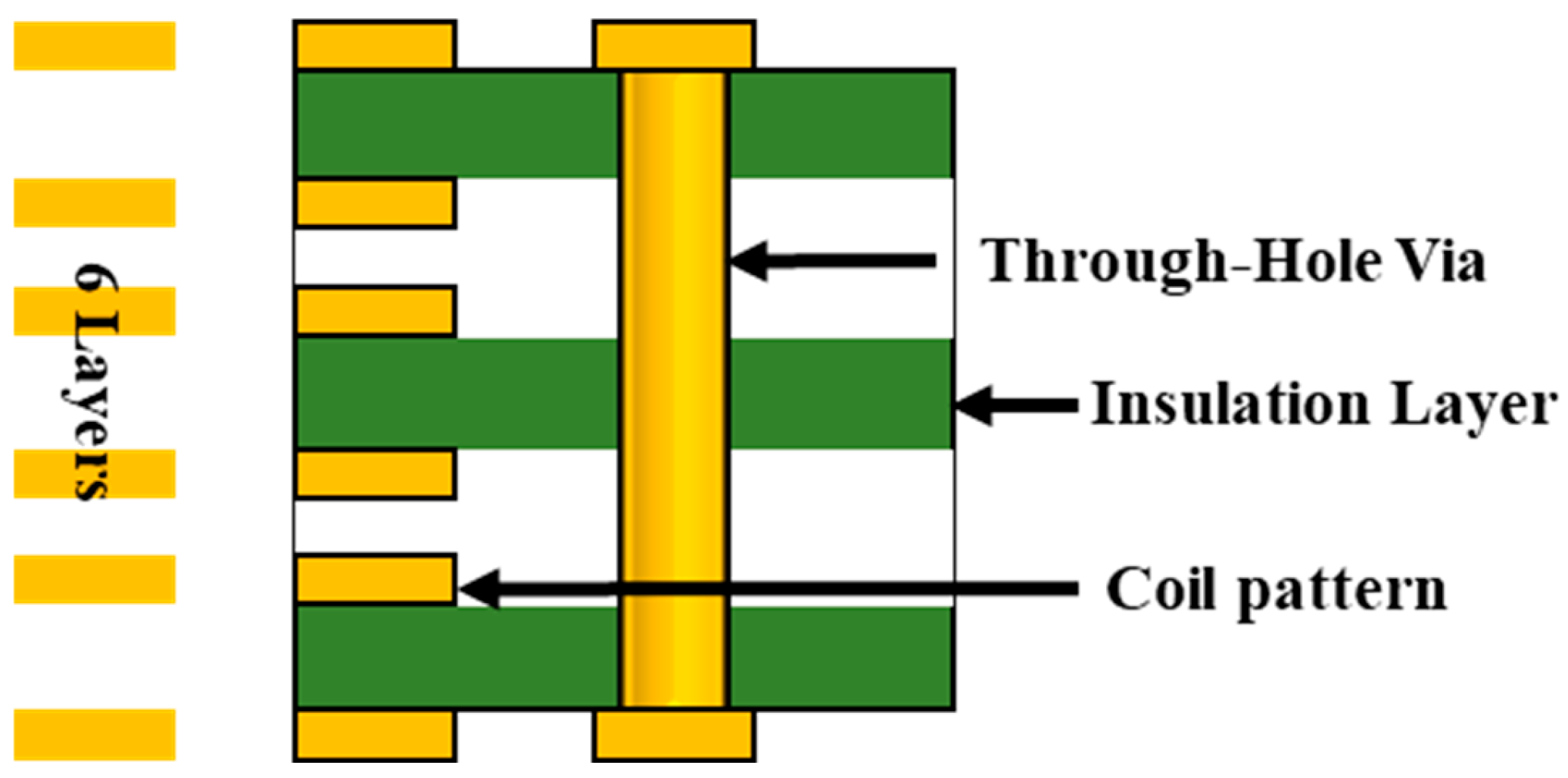
Figure 1 illustrates the layer structure of a printed circuit board (PCB). A PCB is a fundamental platform for supporting and interconnecting electronic components while enabling the transmission of electrical signals and power. As shown in Figure 1, a PCB consists of multiple conductive layers laminated onto an insulating substrate, incorporating via holes for interlayer connectivity and insulation layers to prevent electrical interference. The conductive layers, which are primarily composed of copper, serve as paths for electrical signals and power delivery. These layers are precisely patterned using chemical or physical etching processes, with the conductor width and thickness tailored to meet specific design requirements. PCBs may be classified as single-sided, double-sided, or multilayer structures, with multilayer PCBs playing a particularly important role in improving space utilization. As indicated by the yellow markings on the left side of Figure 1, the substrate illustrated in this study is a six-layer PCB.
The insulation layers electrically isolate adjacent conductive layers while providing mechanical support and structural stability. These layers are commonly fabricated from materials such as FR4 (fiberglass-reinforced epoxy), which offers excellent electrical insulation and thermal stability. FR4 maintains stable performance under elevated temperature conditions and exhibits high mechanical strength, thereby enhancing the reliability of multilayer PCB structures. By ensuring electrical isolation and minimizing signal distortion, the insulation layers contribute to high-performance circuit design.
Via holes enable electrical connections between conductive layers and facilitate reliable current flow throughout the PCB. These vias are typically metallized to ensure stable electrical conduction and are categorized as through-hole vias, buried vias, and blind vias. Through-hole vias extend through the entire PCB and connect all layers, whereas buried vias connect only internal layers. Blind vias connect an outer layer to one or more internal layers, depending on the design requirements. Such via structures reduce interlayer electrical losses and enable efficient electrical interconnection in high-density PCB designs.
In addition, PCBs include auxiliary layers such as solder masks, which protect the conductive traces from corrosion and prevent unintended solder bridging, as well as surface finishes that suppress oxidation. These features improve the durability of the PCB and extend the operational lifetimes of electronic devices. Owing to these structural characteristics and advanced design capabilities, PCBs have become essential components in high-performance electronic systems, particularly in applications requiring compactness and high integration density.

2.2. Application of PCB Stators in Axial Flux Motors

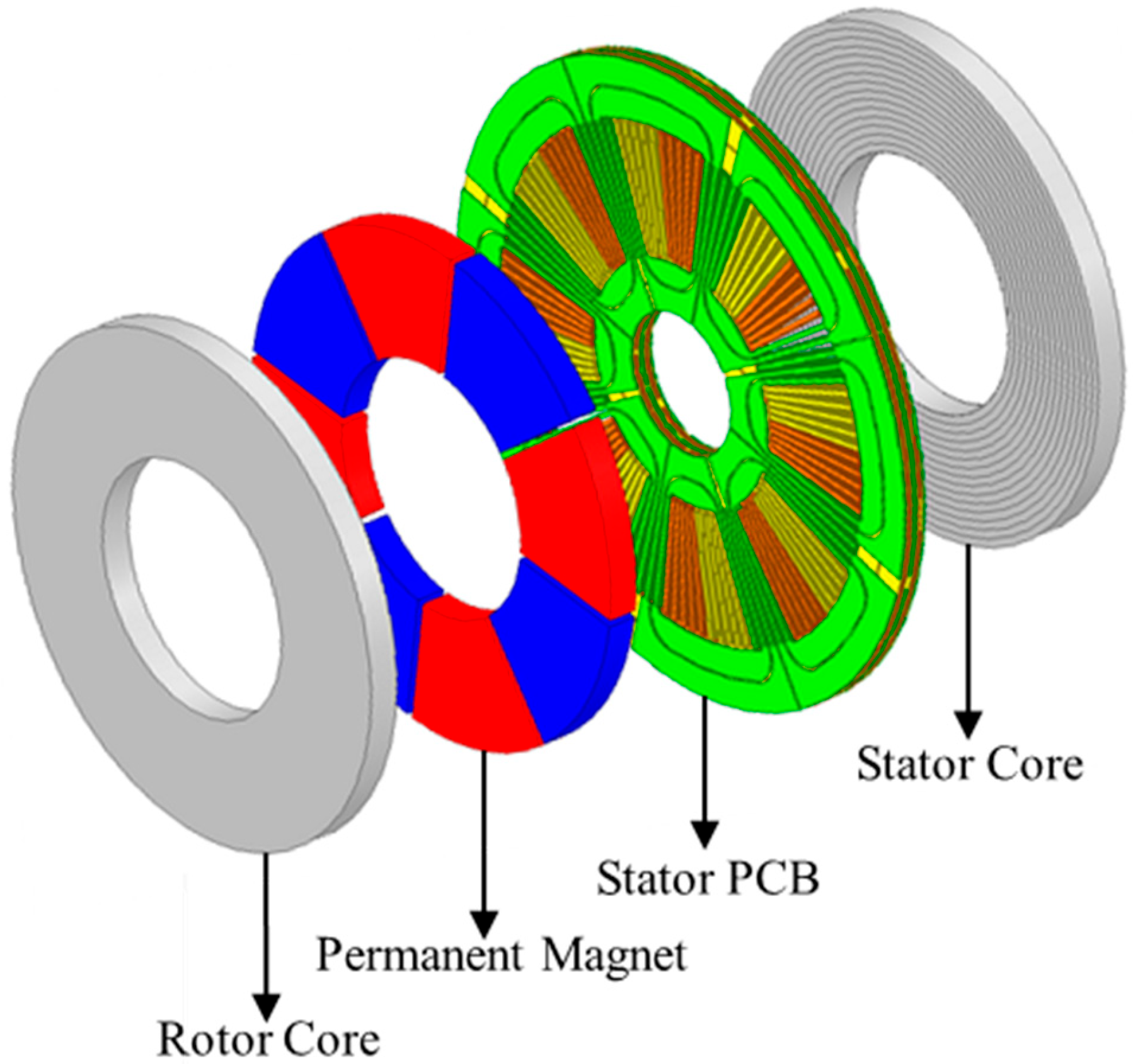
Figure 2 illustrates the structure of an axial flux motor employing a PCB stator. An axial flux motor (AFM) with a PCB stator operates based on the same fundamental electromagnetic principles as conventional electric motors, relying on the interaction between the stator-generated magnetic field and the rotor-mounted permanent magnets. However, as shown in Figure 2, this motor adopts a distinctive structural approach by utilizing a printed circuit board as the stator instead of the traditional slotted cores and wound coils. The stator consists of a PCB and a stator core, while the rotor is composed of permanent magnets and a rotor core. This configuration effectively exploits the thin axial profile characteristic of AFMs, clearly distinguishing them from conventional radial flux motors (RFMs) [15,16].
The stator is implemented using a multilayer PCB structure, in which conductor layers and insulation layers are alternately stacked to distribute the current efficiently. When the current flows through the stator conductors, a magnetomotive force (MMF) is generated, which interacts with the magnetic field produced by the permanent magnets on the rotor. According to Lorentz’s law, this electromagnetic interaction produces a tangential force that generates torque and drives rotational motion.
The rotor consists of permanent magnets arranged to establish the main magnetic flux interacting with the stator, along with a rotor core that provides mechanical support and serves as a magnetic flux path. The rotor core supports the permanent magnets structurally while enabling efficient magnetic flux circulation. This design facilitates effective magnetic coupling between the stator and rotor and contributes to high power density in the AFM configuration investigated in this study.
Axial flux motors employing PCB stators offer significant advantages in applications that demand a compact size and reduced weight. Compared with conventional winding-based stator fabrication methods, PCB-based stators simplify the manufacturing process and reduce the production time. Moreover, the high precision achievable through PCB fabrication ensures a consistent conductor geometry and high reliability. As a result, AFMs with PCB stators provide a promising solution for advanced applications, including electric and hybrid vehicles, and are increasingly recognized as a viable next-generation motor technology.
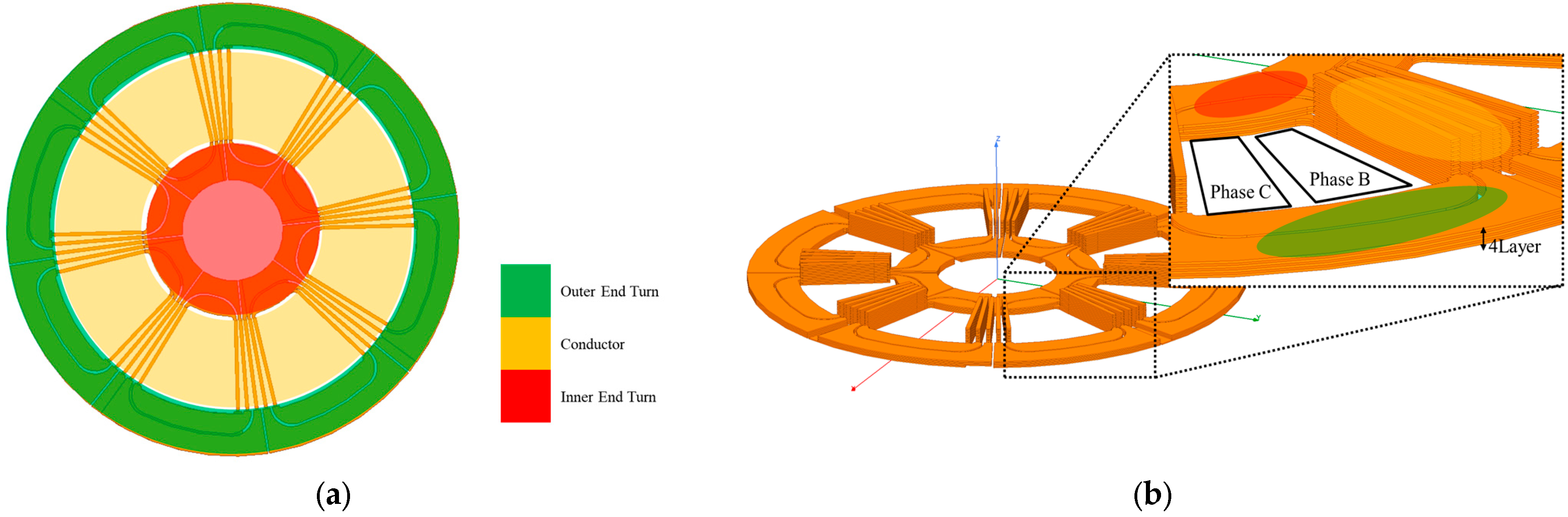
Figure 3 presents the Z-axis view of the PCB based on phase A (a) and the side view of the PCB (b). The coil pattern applied to the stator can be broadly divided into three components, as shown in Figure 3: the inner end-turn, the outer end-turn, and the effective conductor. Among these, the effective conductor plays a critical role in generating torque by interacting with the magnetic flux produced by the permanent magnets as the current flows through it. The inner and outer end-turns are connected to the effective conductors to determine the direction of current flow, thereby ensuring that torque is generated in the correct direction. This function is identical to that of the end-turns in the winding methods of conventional radial flux or axial flux motors.
In PCB stators, the structure of the end-turns differs from that in traditional coil pitch configurations. Since electrical connections within a PCB must be established within a limited number of layers, unique current paths must be designed to prevent overlap with other layers. This design is devised to efficiently utilize the multilayer structure of the PCB while ensuring that each coil pattern operates without interference.
Describing the PCB design based on a 12-layer structure, the effective conductor shown in Figure 3 (highlighted in yellow) utilizes all 12 layers. Meanwhile, the inner and outer end-turns, marked in red and green, are connected by allocating four layers to each of the three phases; this configuration demonstrates the characteristics of a multilayer PCB design. As seen in Figure 3b, the end-turn of phase A is composed of four layers, while the remaining eight layers are occupied by the end-turns of phases B and C. Similarly, regarding the effective conductor, the area adjacent to the phase A effective conductor—which appears as empty space—is actually occupied by the effective conductors of phases B and C. As previously mentioned, unlike the end-turns, the effective conductor is structured to utilize all 12 layers. This multilayer structure maximizes the spatial efficiency of the PCB design and minimizes interference between phases, enabling the configuration of complex circuits within a compact volume.

3. Reference Model and Winding Pattern of PCB Motor

3.1. Configuration of the Basic Winding Pattern in PCB Motors

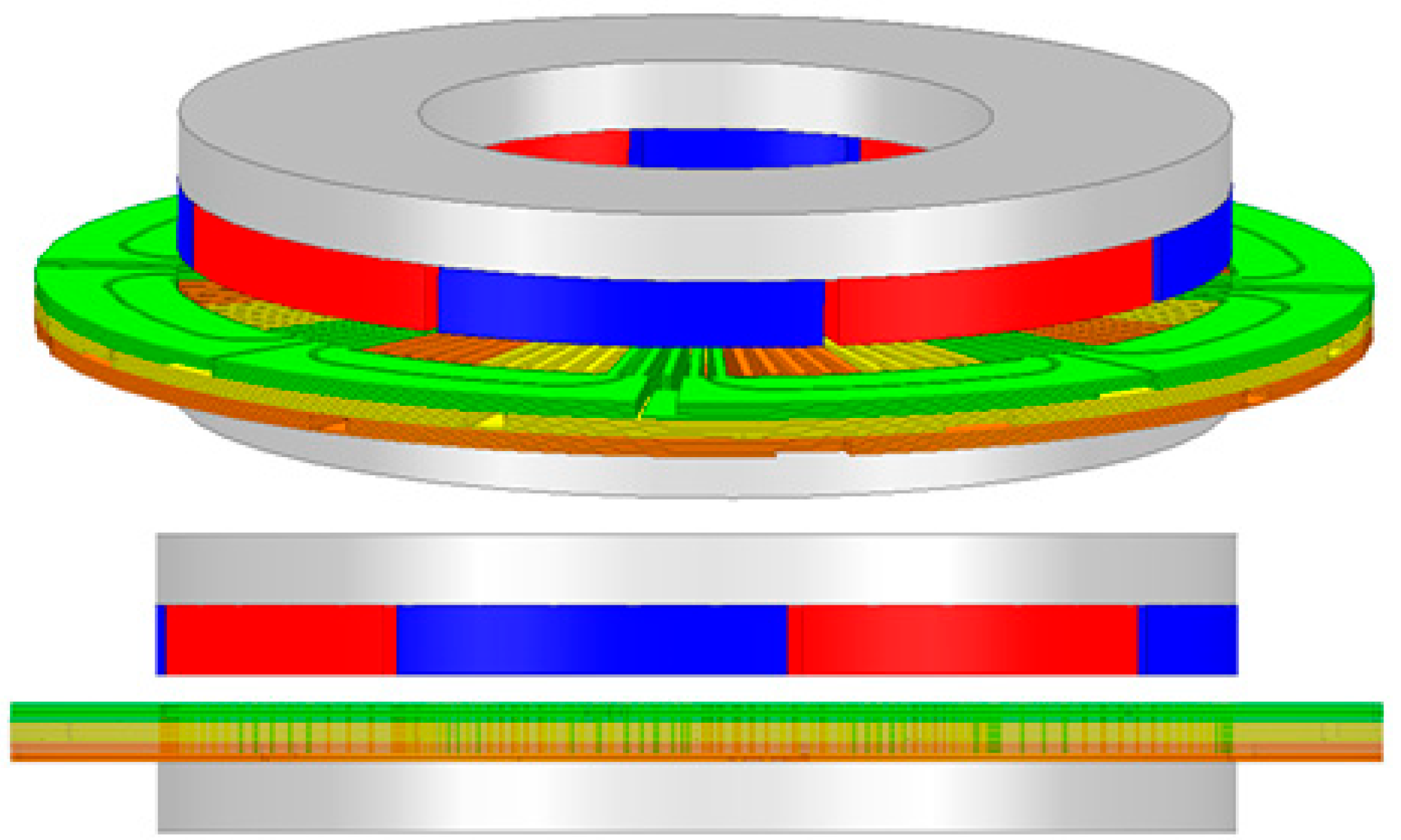
Figure 4 illustrates the reference model, the 8P24S SSSR-type structure. The baseline model of the PCB motor is configured in an 8-pole, 24-slot single-stator single-rotor (SSSR) format, as shown in Figure 2. This model consists of a rotor core, permanent magnets, a stator PCB, and a stator core, consistent with the layout depicted in Figure 2 (structure of axial flux PCB motor, SSSR type).
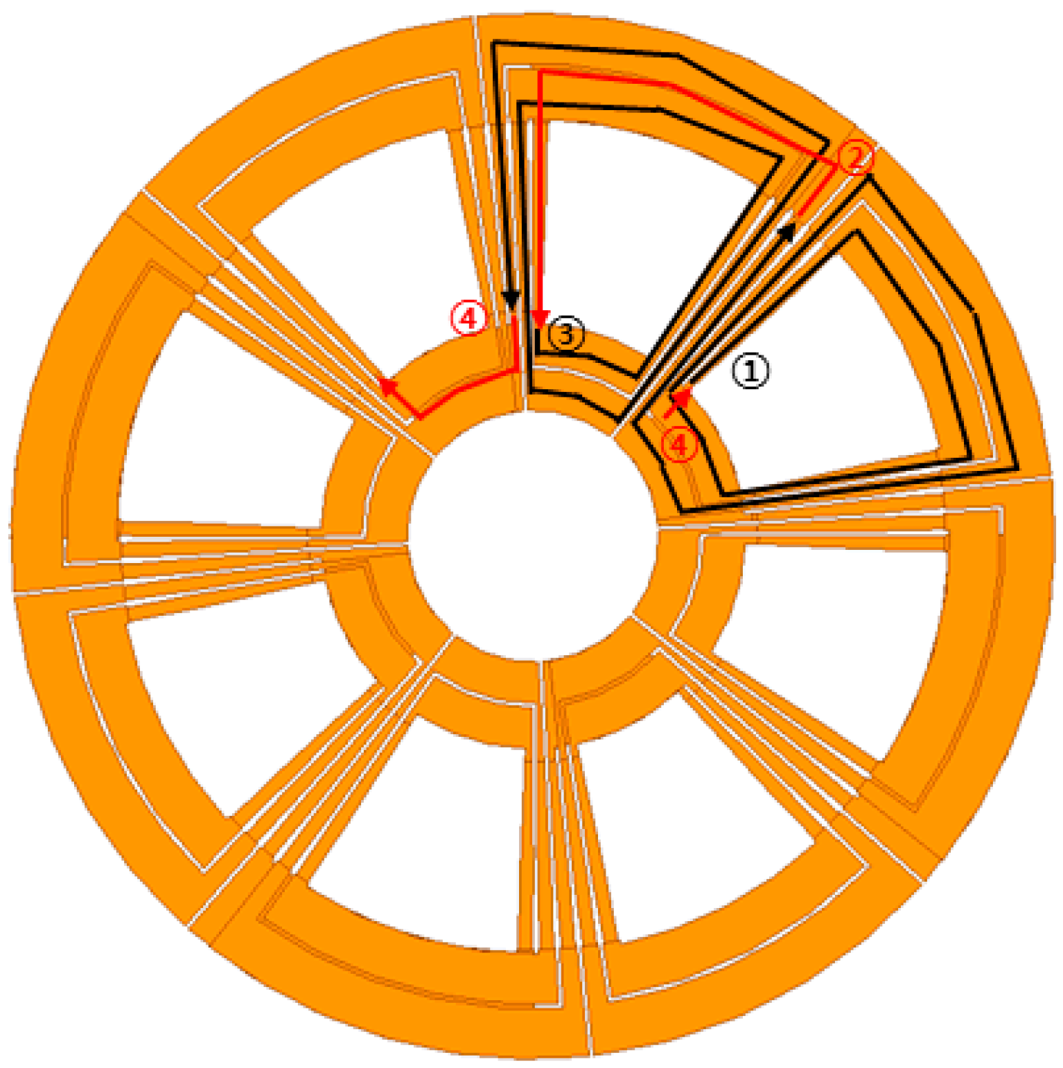
Figure 5 illustrates the current flow of phase A in the reference model PCB. Figure 5 depicts the current flow focusing on phase A of the PCB substrate, which functions as the stator. The current paths for phases B and C follow an identical principle and are therefore omitted.
Describing the current path of phase A, the current follows the trajectory marked by points 1 through 4, as indicated by the black and red arrows. First, the current enters the substrate along path 1, establishing a clockwise spiral flow until it reaches point 2. Due to the limited outer diameter and layer structure of the PCB substrate, connections cannot be continuously routed radially within a single layer. Consequently, as indicated by the red arrow at point 2, the current transfers to a different layer and flows into the adjacent slot.
The current moves to the adjacent slot via a different layer and reaches path 3, where it returns to the original layer and resumes its clockwise spiral flow. Similarly, due to routing constraints within the same layer, the current continues from path 4 to the adjacent slot through another layer. This current trajectory spans two slots and is repeated four times across the eight slots assigned to phase A out of the total 24 slots. Finally, the terminus of path 4 reconnects to path 1, completing the cyclical current flow.
This design presents a unique winding method intended to efficiently arrange current paths within the limited space and multilayer structure of the PCB substrate. This approach considers both the characteristics of axial flux motors and the structural constraints of the PCB, thereby contributing to the realization of high power density and efficiency. Phases B and C are designed according to the same principle and are configured to eliminate interference between phase current paths while ensuring correct current flow for torque generation.

3.2. Characteristics and Performance Analysis of the Reference Model

Table 1 summarizes the performance of the reference model employing the current path illustrated in Figure 5. This study of the 8P24S SSSR-type reference model represents a design and performance evaluation of an axial flux motor utilizing a PCB stator.
When a PCB stator is applied to an axial flux motor, the inner and outer end-turn regions of the PCB protrude beyond the permanent magnets and the core, as shown in Figure 4. This characteristic introduces design variables that differ from those of conventional radial flux motors. In addition to the inner and outer diameters of the core, permanent magnets, rotor, and stator back yokes, the inner and outer diameters of the PCB emerge as additional geometric design parameters. These structural characteristics of the PCB play a critical role in the design optimization process and significantly influence both the power density and efficiency.
In the reference model, carbon steel (S45C) is used for the rotor back yoke, while electrical steel (35PN230) is employed for the stator back yoke. Since the permanent magnets are attached to the rotor back yoke, the magnetic flux rotates synchronously with the rotor and is therefore not subject to time-varying effects in the rotor back yoke. In contrast, the stator back yoke remains stationary, which makes it susceptible to eddy current losses induced by the time-varying component of the permanent magnet flux. To mitigate these losses, the stator back yoke is designed using laminated electrical steel.
In radial flux motors, eddy current losses are typically reduced by stacking electrical steel laminations along the axial direction. However, in axial flux motors, axial stacking is not effective. Instead, a spiral-wound lamination structure, commonly referred to as a “rolled core”, is adopted. This approach alleviates manufacturing challenges associated with radial stacking and effectively reduces eddy current losses, thereby enabling high-performance operation in axial flux motor designs.

3.3. Characteristics and Limitations of the Conventional Winding Arrangement

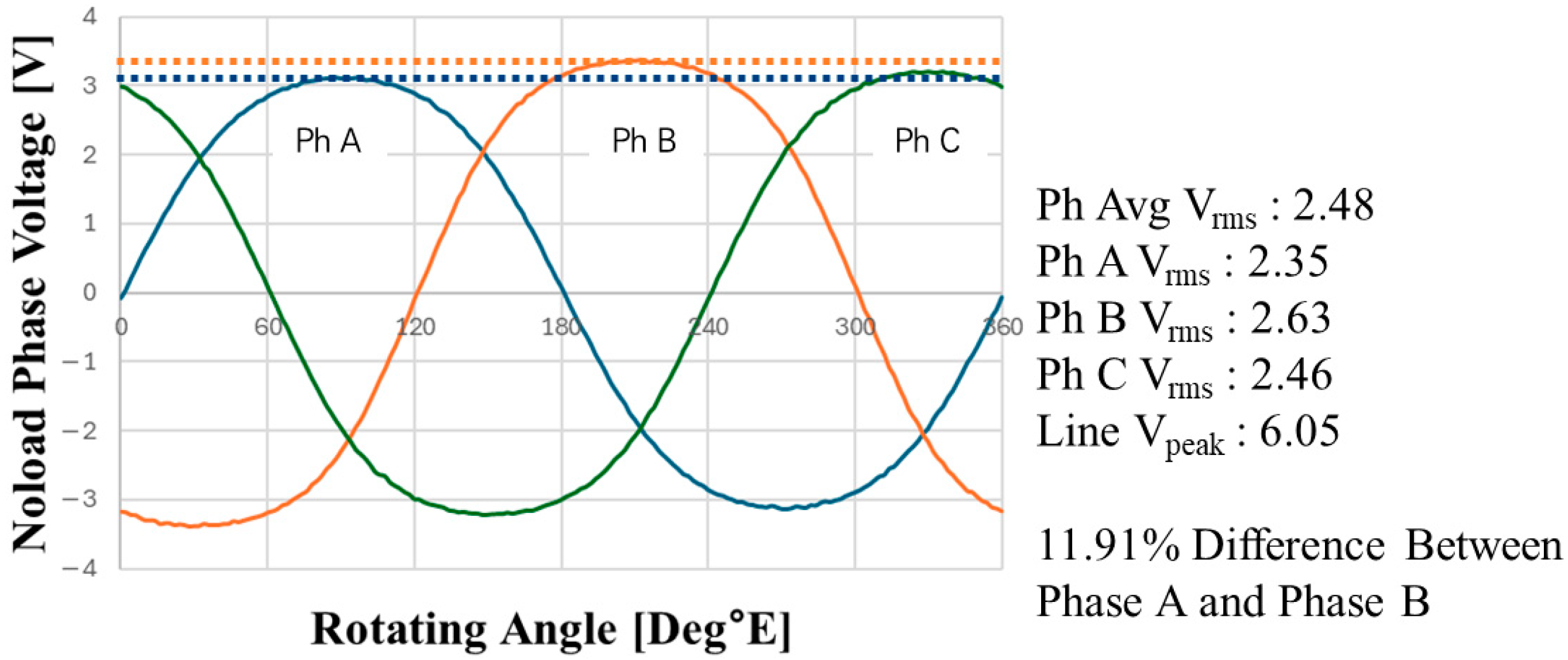
Figure 6 presents the phase back-EMF waveforms of the 8P24S SSSR-type motor, clearly illustrating the imbalance in the back-EMF generated among the phases. As shown in the figure, the RMS values of phase A (blue) and phase B (orange) are 2.35 V and 2.63 V, respectively, corresponding to a difference of 11.91% between the two phases. Such a discrepancy can directly affect current distribution and torque generation, and it represents a critical issue for axial flux motors, where interphase balance is essential.
In particular, phase back-EMF imbalance leads to the degradation of the motor’s electrical performance. First, it induces distortion in phase currents, which increases electrical losses and consequently reduces the motor efficiency. Second, in sensorless control schemes, back-EMF is used to estimate the rotor position; therefore, imbalance among phases degrades the accuracy of position estimation and adversely affects the control stability. Third, increased torque ripple results in vibration and acoustic noise, making precise speed control more difficult.
From the graph, it can be observed that phase B exhibits higher back-EMF than the average phase value, whereas phase A shows a lower value, confirming the insufficient interphase balance. This imbalance is likely attributable to issues in the phase arrangement and winding design. As illustrated in Figure 4, the relative distance between the permanent magnets and the end-turns of each phase follows the sequence B → C → A (B: green, C: yellow, A: orange). Since this sequence exhibits the same trend as the back-EMF magnitude, it can be inferred that the imbalance arises from the end-turn arrangement order.
Therefore, to address this issue, the optimization of the phase arrangement and improvement of the winding pattern are required. A detailed analysis of this phenomenon and the corresponding mitigation strategy are presented in Section 4. Through these efforts, the phase back-EMF imbalance can be alleviated, thereby improving the overall performance and operational stability of the motor.

3.4. Analysis of the Causes of Back-EMF Imbalance

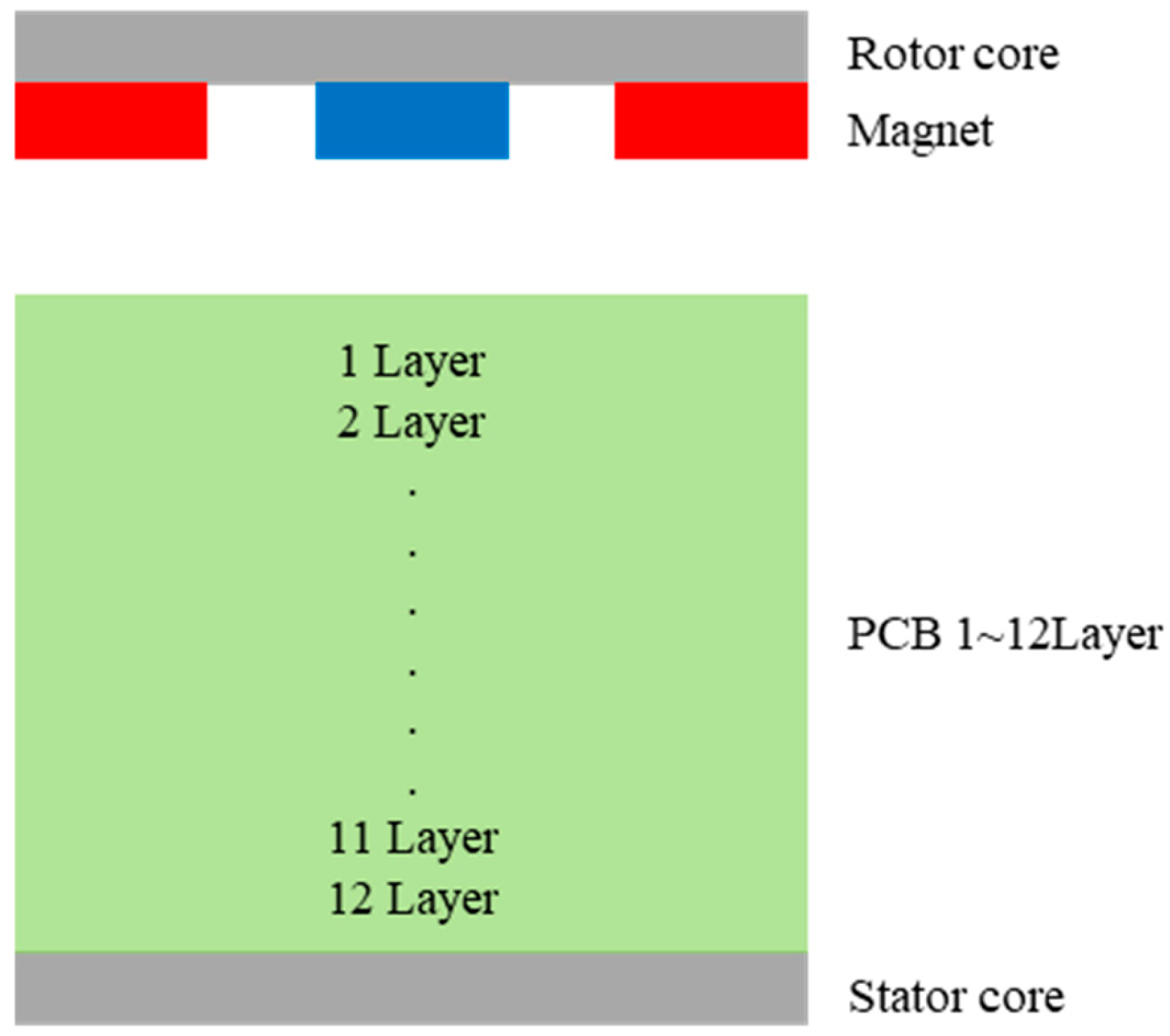
To facilitate clarity and avoid confusion in the description of the PCB layers, the layers are indexed from layer 1 to layer 12, as illustrated in Figure 7, starting from the layer closest to the permanent magnets and proceeding to the layer farthest from them.
As shown in Figure 6, the magnitude of the phase back-EMF is the largest for phase B, which is located closest to the permanent magnets serving as the flux source, while phase A, positioned nearest to the stator back yoke and farthest from the magnets, exhibits the smallest back-EMF. This observation suggests that the back-EMF magnitude is closely related to the positional relationship between the permanent magnets and the end-turn locations.
In the 8P24S SSSR model, the back-EMF imbalance primarily originates from the structural characteristics of the PCB stator and the asymmetry of the current flow. The end-turns of each phase (A, B, and C) occupy four layers and are arranged in an adjacent manner. Specifically, phase A is located in layers 9–12, phase C in layers 5–8, and phase B in layers 1–4. While this configuration offers simplicity in design and ease of implementation, it inherently introduces imbalances in current density and magnetic characteristics.
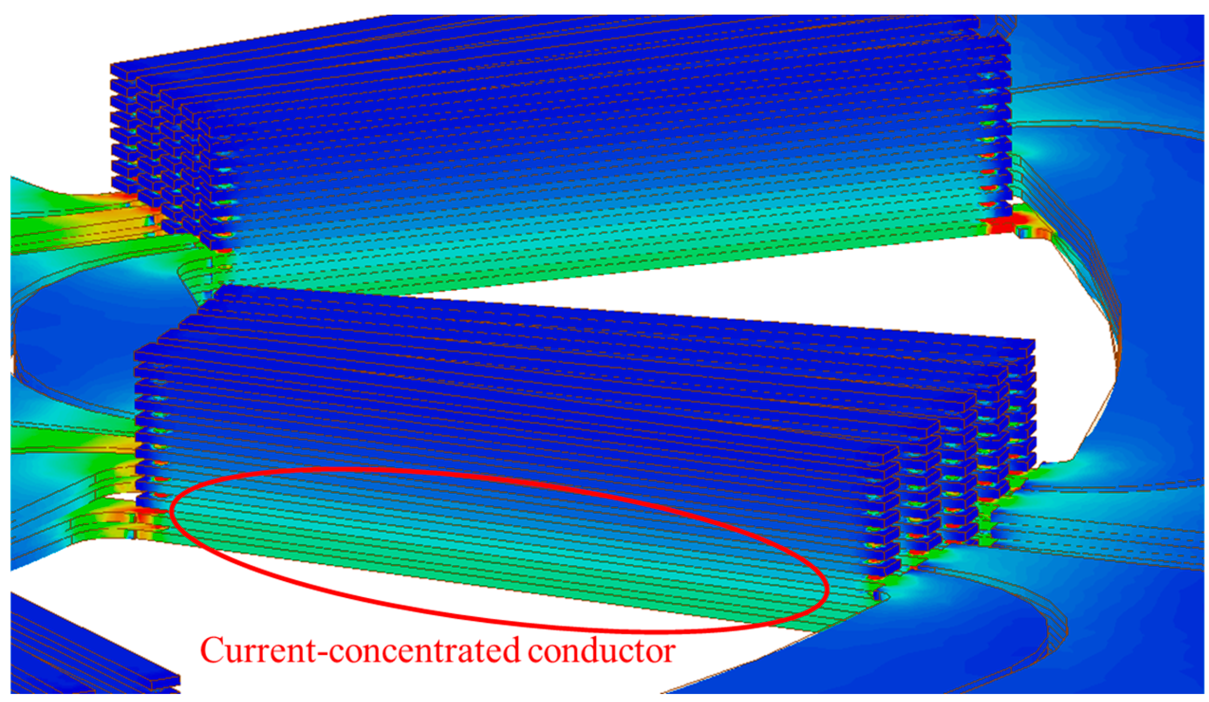
An analysis of the current density distribution (J-plot) for phase A, as shown in Figure 8, confirms that the current flow is concentrated exclusively within the effective conductors of layers 9 through 12. Notably, almost no current flows in layers other than layers 9 through 12. This imbalance in current density results in differences in phase back-EMF and constitutes a primary cause of motor performance degradation, highlighting the need for improvements in the current path design and end-turn structure.
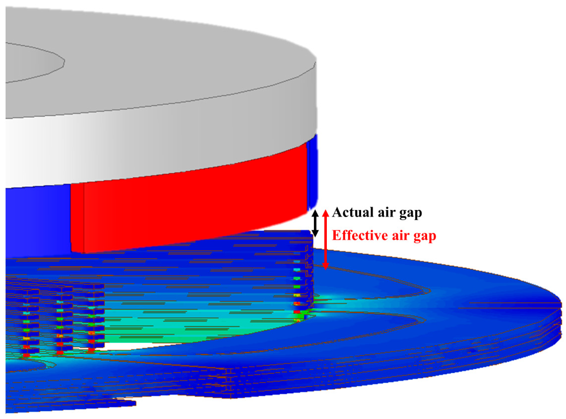
Examining the physical air gap structure, the air gap extends from the permanent magnet to the uppermost effective conductor (layer 1). However, since the current flow is primarily confined to layers 9 through 12, the air gap effectively widens, as illustrated in Figure 9. This increased air gap is hereinafter referred to as the effective air gap. Such widening increases magnetic loss, and variations in the degree of expansion among phases can lead to back-EMF imbalance.
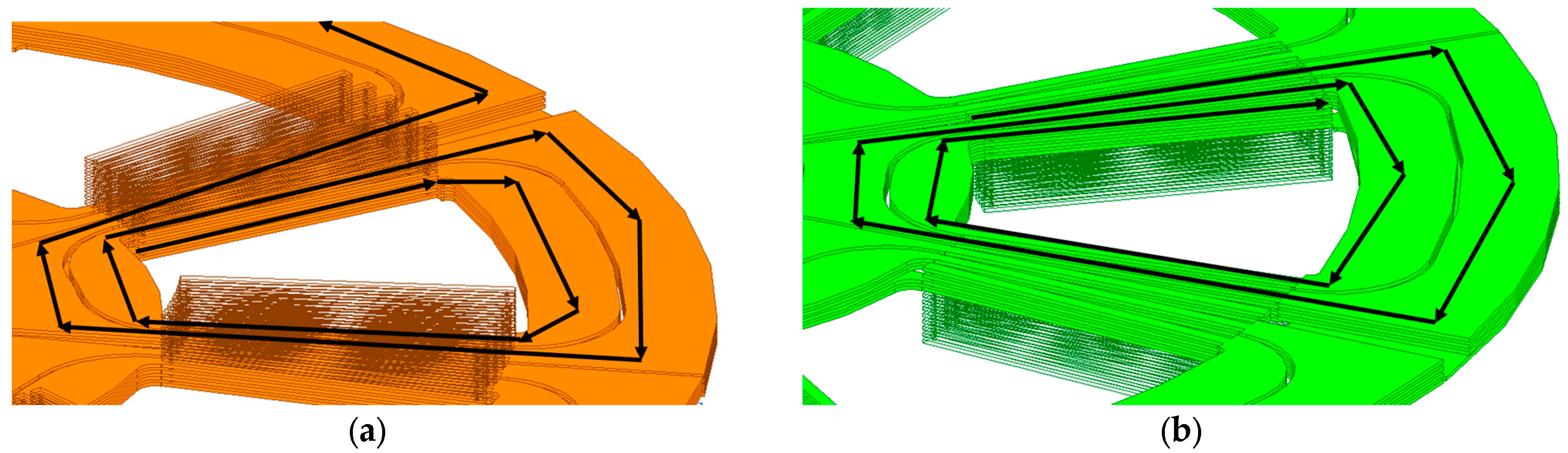
The closed loops within the motor windings play a crucial role in torque generation through magnetic interaction as the current flows through each phase. Figure 10 illustrates the formation process and structural characteristics of the closed loops for each phase using the coil patterns of phases A and B. In particular, the closed loops of phases A, B, and C are located at different distances from the permanent magnets; these positional differences influence the magnetic characteristics and current paths of each phase.
As shown in Figure 9, the effective conductors in the layers containing the end-turns play a pivotal role in forming the closed loops. Conversely, although the effective conductors in layers without end-turns are included in the current path, their contribution to the closed loops is relatively minor. In other words, the closed loops of phases A and B are situated at different distances from the permanent magnets. To clearly visualize this effect, the effective conductors in layers without end-turns are rendered semi-transparently in Figure 10. This visualization facilitates an understanding of the role and structural distribution of each layer in closed-loop formation.
Figure 10 visualizes only the effective conductors that substantially function as closed loops, selectively representing those situated in the same layers as the end-turns. Although the effective conductor of each phase is physically composed of 12 layers, this illustration emphasizes that the effective conductors in the specific layers housing the end-turns make the primary contribution to closed-loop formation.
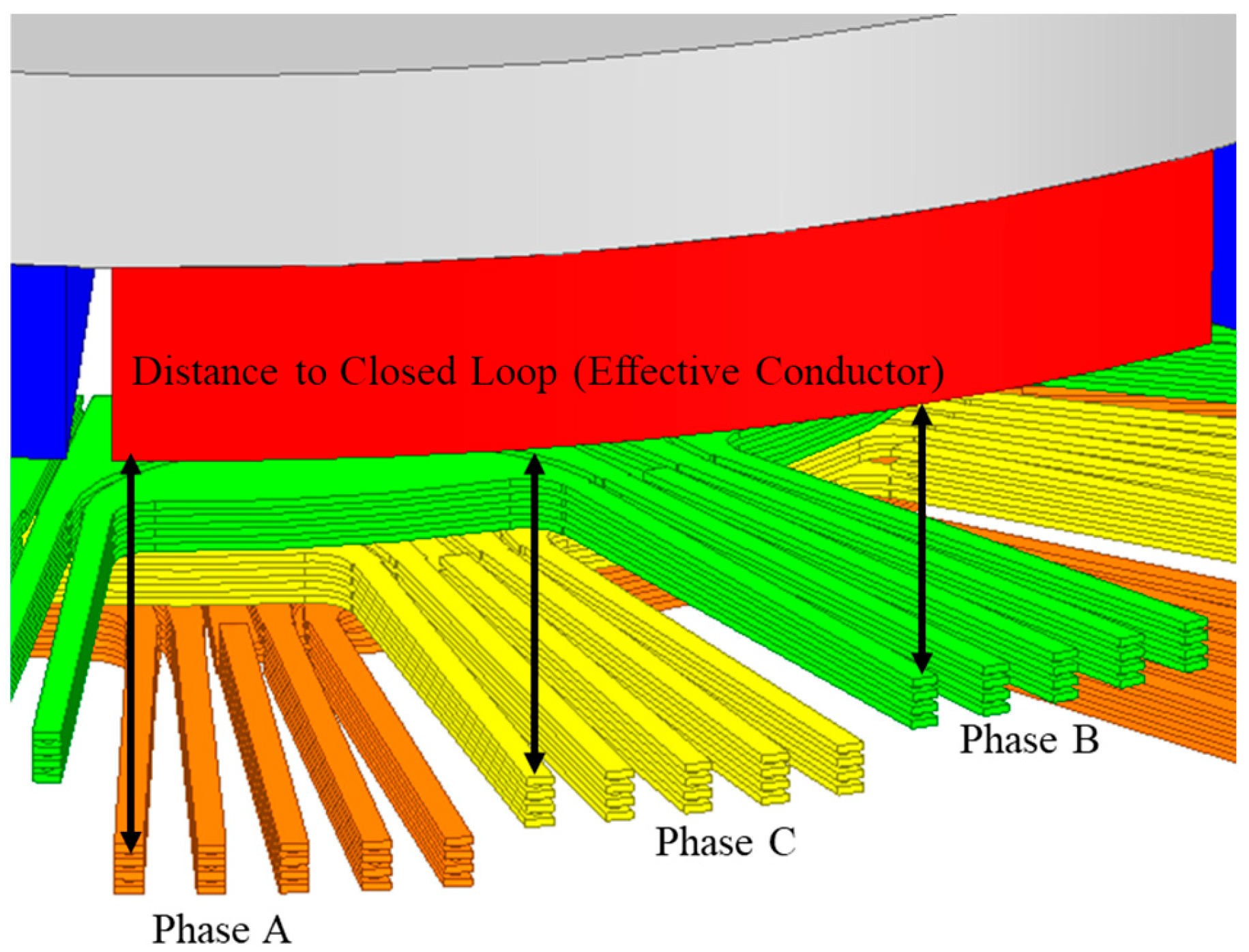
Through this visualization, it is evident that the effective conductors serving as closed loops for each phase (A, B, and C) are situated in distinct layers. This is illustrated more specifically in Figure 11, which confirms that the distance between the permanent magnets and the effective conductors forming the closed loops differs for each phase. This variation in distance influences the magnetic characteristics and current flow of each phase and may lead to phase back-EMF imbalance.
In conclusion, the effective conductors in the layers where the end-turns are located play a pivotal role in forming the closed loops, and the positions of the layers connected to the end-turns are a primary factor determining the distance from the permanent magnets.
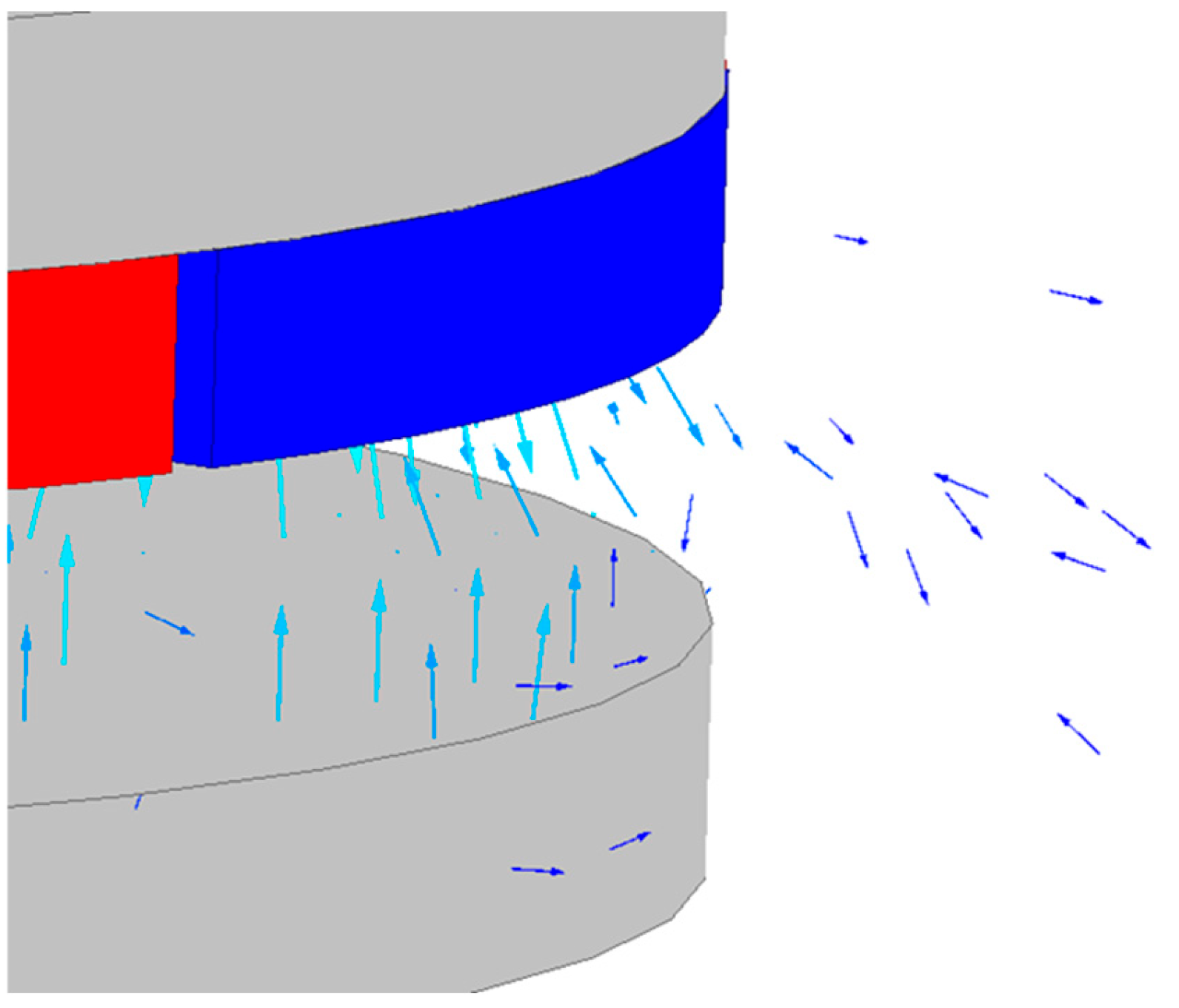
Figure 12 visualizes the magnetic flux generated by the permanent magnets in the reference model using finite element analysis (FEA). The PCB substrate is excluded from the visualization to clearly display the magnetic flux vectors, thereby enabling the clearer observation of the flux flow and its characteristics.
Owing to its non-magnetic nature, the PCB stator exhibits permeability similar to that of the air gap. This distinguishes it from conventional motor designs that employ high-permeability materials, such as electrical steel or SMC cores, for the stator. Consequently, from a magnetic circuit perspective, the PCB substrate is treated as equivalent to the air gap, such that the magnetic flux generated by the permanent magnets passes continuously through both the mechanical air gap and the PCB substrate. As a result, the magnetic air gap becomes effectively larger than the mechanical air gap alone, creating a condition in which the flux path encounters a significantly increased effective air gap.
The magnetic flux generated by the permanent magnets passes through the air gap, links with the PCB substrate, and circulates through the stator back yoke. However, because the magnetic air gap in PCB stator applications is larger than that in conventional motors, flux leakage—where the flux fails to link with the PCB and instead leaks—becomes more pronounced as the distance from the permanent magnets increases. As shown in Figure 12, this leakage flux leads to a reduction in magnetic flux density in specific regions of the PCB, particularly those farther from the permanent magnets. This reduction becomes more prominent as the distance between the PCB substrate and the permanent magnets increases or as the PCB thickness increases.
As discussed previously, the closed loops of each phase (A, B, and C) are located at different distances from the permanent magnets. Furthermore, since the flux density decreases due to leakage with increasing distance from the permanent magnets, each phase experiences a different air gap flux density. This disparity results in an imbalance in magnetic flux distribution among the phases and constitutes the primary cause of phase back-EMF imbalance. Therefore, design improvements are required to equalize the air gap flux density and reduce back-EMF differences to a uniform level. This paper proposes an approach to address these issues.

4. Mitigation of Back-EMF Imbalance and Design of High-Performance PCB Motors

Performance Evaluation and Verification Based on PCB Stator End-Turn Distribution

The current flows intensively through the effective conductors in the layers where the end-turns are located, forming closed loops centered around them. These closed loops exhibit distinct characteristics depending on the end-turn layout of each phase, resulting in varying distances from the permanent magnets and, consequently, deviations in phase back-EMF. Although equalizing the average end-turn height may mitigate this back-EMF imbalance, verification requires a comparative set that includes combinations with different average end-turn heights for each phase.
Therefore, this study examines the effectiveness of equalizing the average end-turn height in mitigating back-EMF imbalance by comparing a total of four configurations, including the existing end-turn connection.
Through this approach, the impact of end-turn placement on the motor’s back-EMF characteristics is quantitatively analyzed, and the relationship between the end-turn distribution and interphase characteristics is elucidated.
Furthermore, the distribution of end-turns influences the current path and the utilization of effective conductors. In the existing structure, only specific effective conductors—namely, those in layers containing end-turns—serve as current paths among the 12 layers. However, when the end-turns are evenly distributed, effective conductors across a greater number of layers can be incorporated into the current path. This suggests the potential to improve electrical resistance through enhanced current density uniformity, and a corresponding analysis is conducted concurrently.
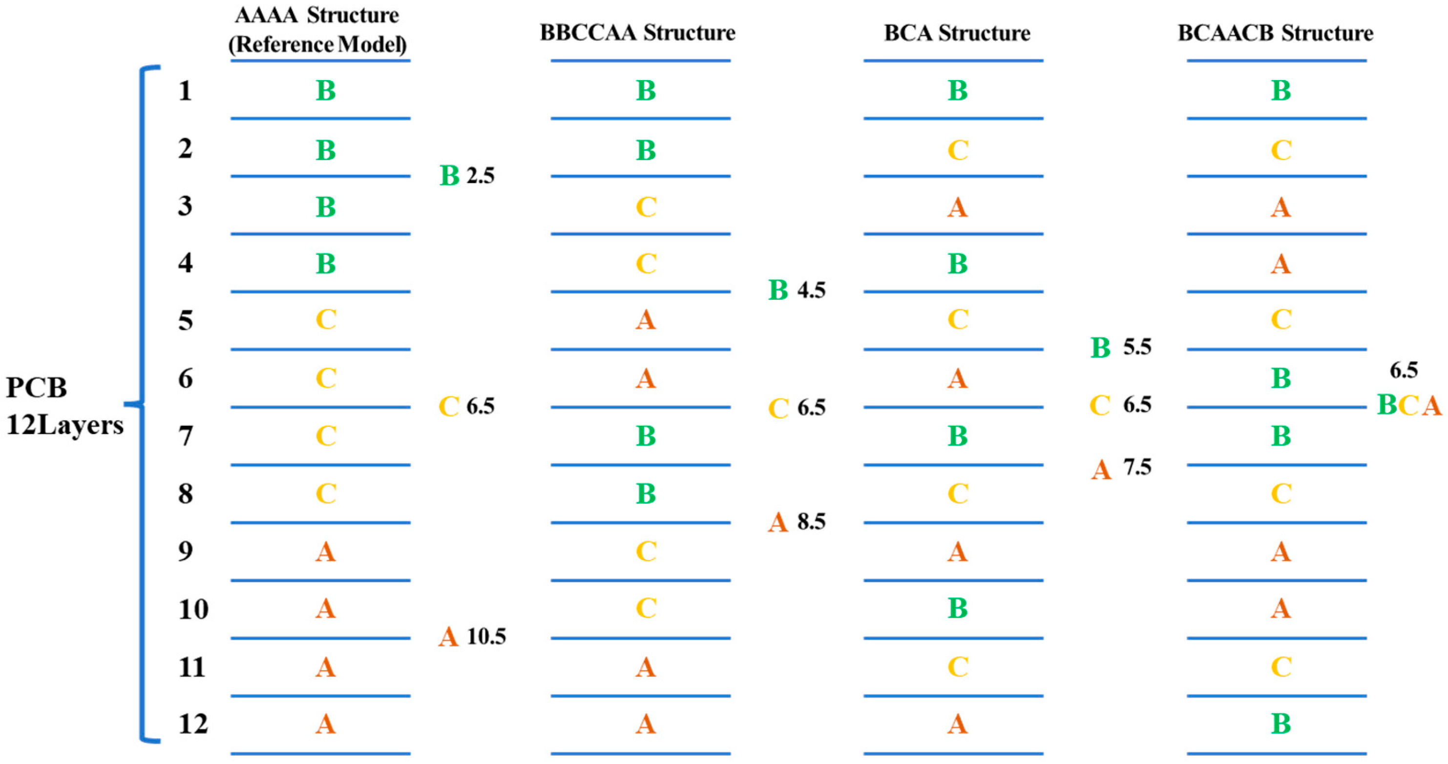
Figure 13 visualizes the four previously mentioned end-turn combinations, clearly illustrating the structural characteristics and layout of each. For the optimal end-turn combination selected in Section 3, Group 1 (layers 1, 6, 7, and 12) is assigned to phase B, Group 2 (layers 2, 5, 8, and 11) to phase C, and Group 3 (layers 3, 4, 9, and 10) to phase A. This assignment is determined by considering the existing end-turn connection order of B → C → A relative to the permanent magnets. Specifically, by assigning Group 1 (including layer 1) to phase B, Group 2 (including layer 2) to phase C, and Group 3 (including layer 3) to phase A, the sequence originating from the permanent magnets is kept consistent with the conventional configuration.
Based on the end-turn connection flow, the optimal combination follows the sequence B → C → A → A → C → B and is designated as the BCAACB type. This configuration is distinguished from the AAAA type (B → B → B → B → C → C → C → C → A → A → A → A), which is the end-turn connection structure employed in the reference model. Compared with the conventional AAAA type, the BCAACB type reflects the design goal of improving the interphase balance by more evenly distributing the end-turn layout.
In addition, the BBCCAA type and BCA type are included for comparison. These combinations correspond to intermediate values of average end-turn height deviation between the reference model and the optimal configuration (BCAACB type) and are established as benchmarks to analyze the impacts of different end-turn arrangements on back-EMF balance.
Table 2 presents the average end-turn height for each phase across the four combinations. The values listed to the right of each combination in Figure 13 represent the average end-turn heights for the corresponding phases. As indicated in the table, the average end-turn heights become progressively more uniform in the order of AAAA, BBCCAA, BCA, and BCAACB. If equalizing the average end-turn height is effective in improving phase back-EMF imbalance, the mitigation of this imbalance is expected to follow the same trend in the aforementioned order.
Figure 5, as previously described, visualizes the current flow for phase A in the 8P24S PCB substrate, illustrating the propagation of the current within the PCB coil pattern.
Due to the inherent characteristics of the PCB, when electrical routing within a single layer is constrained, the current transitions to another layer through via holes to form a closed loop. In this process, the distribution of the end-turns serves as a critical design factor influencing both the current path and the resulting current density.
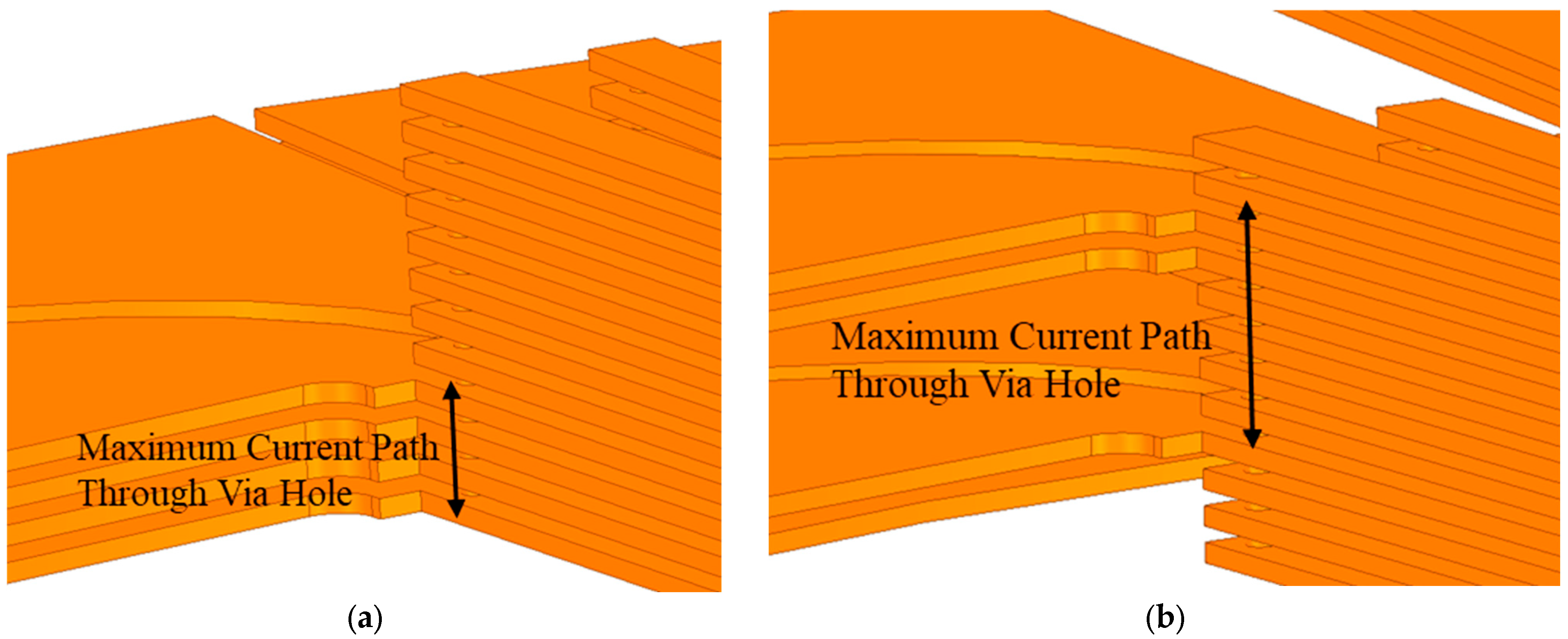
When the end-turns are evenly distributed, the current flows more uniformly by effectively utilizing conductors across all 12 layers. However, this improved uniformity comes at the expense of an increased current path length through the via holes. As shown in Figure 14, in the conventional end-turn structure, the end-turns of each phase are placed adjacently, resulting in a relatively short current path within the via holes. In contrast, although the BCAACB-type end-turn structure provides a more evenly distributed end-turn layout, the corresponding current path through the via holes is noticeably longer.
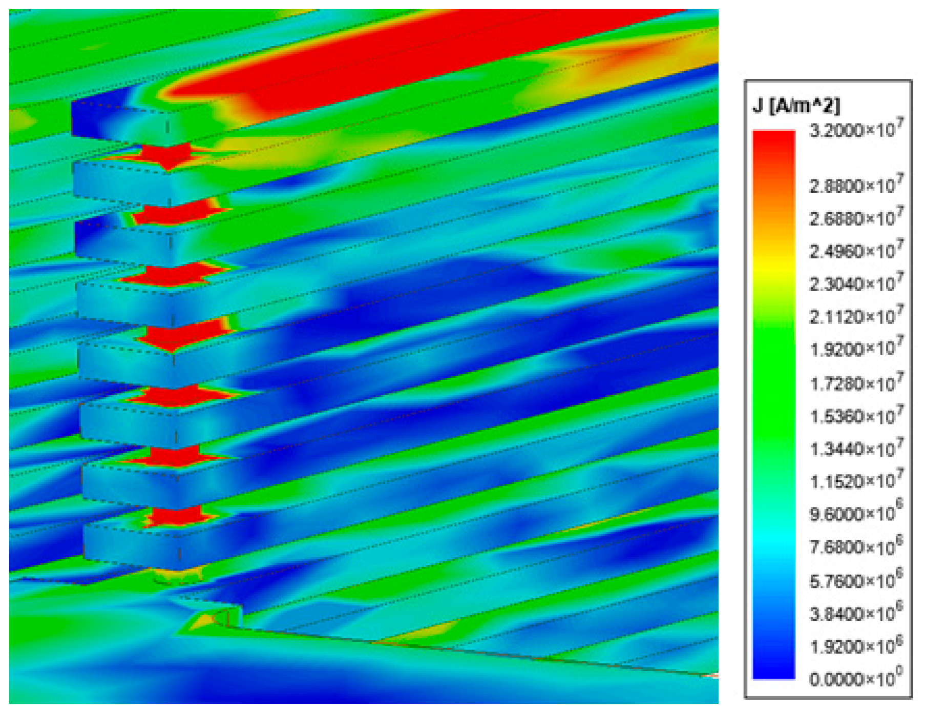
Notably, the J-plot results for the via holes in the conventional end-turn structure of phase A, as shown in Figure 15, reveal a high current density concentrated within the via holes, indicating that the current flow is highly localized as it traverses these regions.
Although the BCAACB-type end-turn structure results in a longer current path through the via holes, it promotes the more uniform distribution of the current among the effective conductors.
Consequently, the increase in resistance associated with the elongated via hole current path may be offset by the improved utilization of effective conductors enabled by the distributed end-turn layout. To evaluate the net effect of these competing factors on resistance, a resistance analysis was performed prior to the back-EMF analysis.
Based on the resistance analysis results presented in Table 3, it is confirmed that the non-adjacent end-turn distribution exhibits superior characteristics in terms of average resistance and phase resistance variance compared to the adjacent structure. Specifically, arranging the end-turns in a non-adjacent manner allows the current to flow more uniformly across the effective conductors of all 12 layers, thereby reducing current concentration and minimizing phase resistance imbalance. Furthermore, a general trend of decreased resistance is observed as the end-turns are more evenly distributed throughout the structure, which is attributed to improved uniformity in current flow.
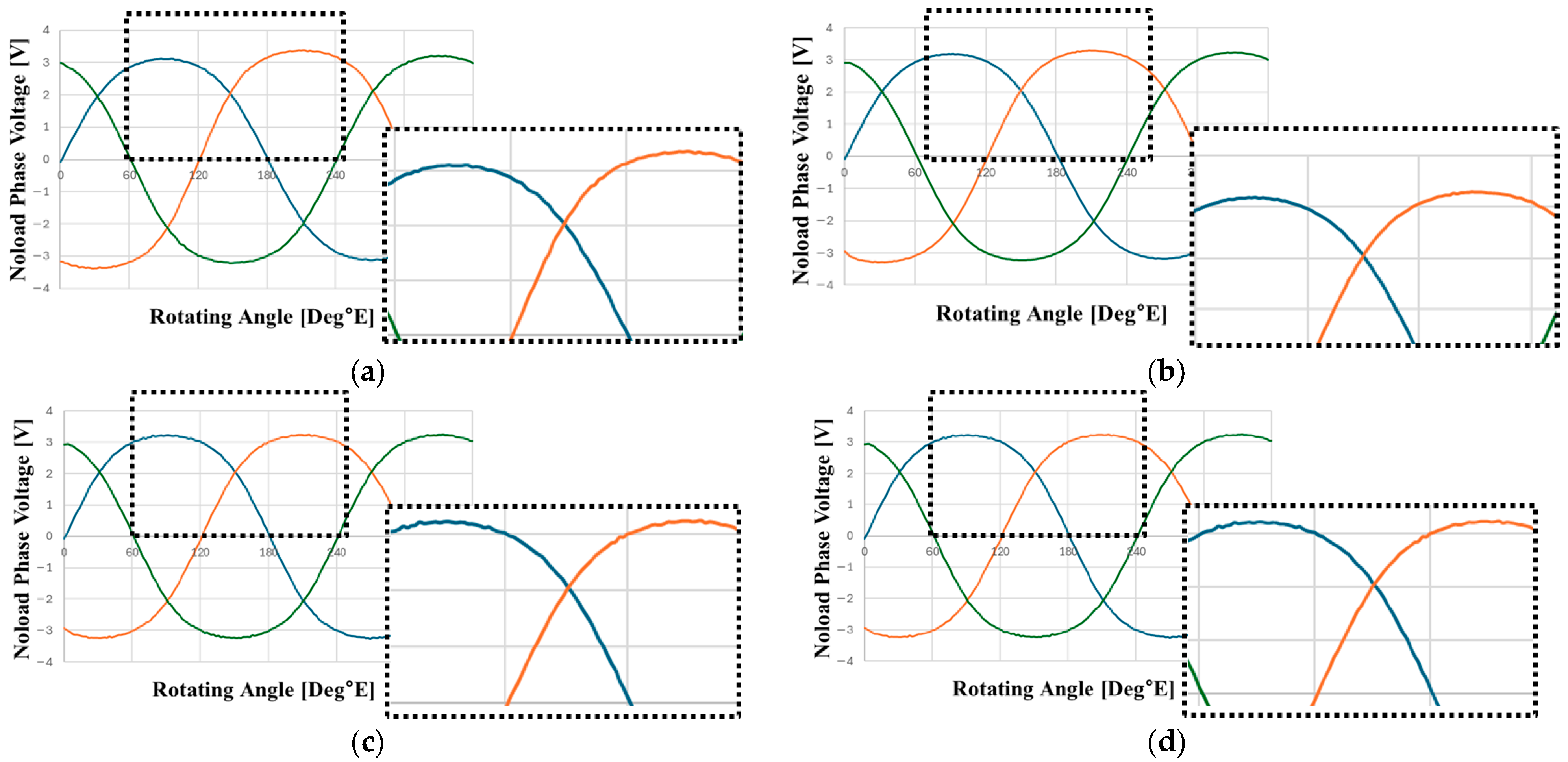
Figure 16 presents the phase back-EMF waveforms for the conventional end-turn method as well as the BBCCAA, BCA, and BCAACB configurations. Additionally, Table 4 summarizes the phase back-EMF values, including their average and RMS values, along with the deviation between the minimum and maximum values.
First, the magnitude of the phase back-EMF remains at a similar level across the different end-turn connection methods. However, differences are observed among the individual phases. As indicated by the average end-turn heights for each combination and phase in Table 2, the average end-turn heights become progressively more uniform in the order of AAAA, BBCCAA, BCA, and BCAACB.
Consistent with this trend, as the average end-turn heights among the phases become more equal, the deviation between the minimum and maximum phase back-EMF decreases in the same sequence: AAAA, BBCCAA, BCA, and BCAACB. For the BCAACB type, derived using Python code, the deviation between the minimum and maximum values is the lowest at 0.64%. This confirms that equalizing the average end-turn height effectively mitigates phase back-EMF differences.
Consequently, the BCAACB type—exhibiting superior characteristics in terms of phase resistance, phase resistance variance, and back-EMF deviation—is identified as the optimal end-turn distribution structure, and its performance is further analyzed in Table 5.
Table 5 presents the performance characteristics of the motor with the BCAACB end-turn structure applied. While the efficiency of the 8P24S 12-layer model in Table 1 is 79.26%, it increases by 3.28 percentage points to 82.54% following the improvement in end-turn distribution. This enhancement is primarily attributed to the reduction in copper loss resulting from improved resistance characteristics; consequently, the required current decreases, further contributing to the reduction in copper loss.

5. Results

In this paper, an optimized design is proposed to mitigate the back-EMF imbalance occurring in axial flux motors utilizing PCB stators. The results indicate that the non-adjacent end-turn structure (BCAACB type) is the most effective in mitigating back-EMF imbalance and demonstrates superior performance in terms of average resistance and phase resistance variance.
By comparing the conventional end-turn connection method with the optimized structure, it is confirmed that equalizing the average end-turn height of each phase reduces the deviation between the minimum and maximum back-EMF to 0.64%. Furthermore, the results reveal a trend in which the phase resistance variance decreases as the end-turns are arranged in a non-adjacent manner.
In addition, the motor efficiency increases by 3.28 percentage points, from 79.26% in the conventional model to 82.54%. These findings provide foundational insights for the design of axial flux motors that achieve high power density and high efficiency within limited spaces.
The design process proposed in this study serves as an effective methodology for enhancing the performance of axial flux motors and is expected to be applicable to future motor designs across a wide range of applications.

Author Contributions

Conceptualization, W.-H.K.; methodology, M.-S.Y.; modeling, M.-K.H.; simulation and analysis, M.-S.Y. and M.-K.H.; software, S.-H.K. and D.-W.N.; validation, M.-S.Y.; experimental verification, D.-W.N.; data curation, M.-K.H.; writing—original draft preparation, M.-S.Y.; writing—review and editing, D.-W.N. and S.-H.K.; visualization, S.-H.K.; supervision, W.-H.K. All authors have read and agreed to the published version of the manuscript.

Funding

This work was partly supported by the Korea Institute of Energy Technology Evaluation and Planning (KETEP) grant funded by the Korea government (MOTIE) (20214000000060, Department of Next Generation Energy System Convergence based-on Techno-Economics—STEP) and the Technology Innovation Program (RS-2025-02317505, Industrial Strategic Technology Development Program Development of High Power Density Electric Traction System for EV with Multi pole (over 12 poles) Traction Motor) funded By the Ministry of Trade, Industry & Energy (MOTIE, Korea).

Institutional Review Board Statement

Not applicable.

Informed Consent Statement

Not applicable.

Data Availability Statement

The original contributions presented in this study are included in the article. Further inquiries can be directed to the corresponding author.

Conflicts of Interest

Author Min-Su Youn is currently employed by LG Magna e-Powertrain. The research was conducted prior to this employment and was not supported by the company. The remaining authors declare no conflict of interest.

References

  1. Jung, W.-S.; Lee, H.-K.; Lee, Y.-K.; Kim, S.-M.; Lee, J.-I.; Choi, J.-Y. Analysis and Comparison of Permanent Magnet Synchronous Motors According to Rotor Type under the Same Design Specifications. Energies 2023, 16, 1306. [Google Scholar] [CrossRef] [Scilit]
  2. Hao, Z.; Ma, Y.; Wang, P.; Luo, G.; Chen, Y. A Review of Axial-Flux Permanent-Magnet Motors: Topological Structures, Design, Optimization and Control Techniques. Machines 2022, 10, 1178. [Google Scholar] [CrossRef] [Scilit]
  3. Choi, D.-H.; Han, H.-S.; Hong, M.-K.; Jung, D.-H.; Kim, W.-H. Design for Loss Reduction in a Compact AFPM Electric Water Pump with a PCB Motor. Energies 2025, 18, 2538. [Google Scholar] [CrossRef] [Scilit]
  4. Pulvirenti, B.; Puccetti, G.; Semprini, G. Dynamic Energy Consumption Modeling for HVAC Systems in Electric Vehicles. Appl. Sci. 2025, 15, 3514. [Google Scholar] [CrossRef] [Scilit]
  5. Gmyrek, Z. Optimal Electric Motor Designs of Light Electric Vehicles: A Review. Energies 2024, 17, 3462. [Google Scholar] [CrossRef] [Scilit]
  6. Kim, H.-J.; Baek, S.-W. Multi-Objective Optimal Design of an Axial Flux Permanent Magnet Motor for In-Wheel Drive Considering Torque Ripple Reduction. Energies 2025, 18, 4936. [Google Scholar] [CrossRef] [Scilit]
  7. Keskin Arabul, F.; Senol, I.; Oner, Y. Performance Analysis of Axial-Flux Induction Motor with Skewed Rotor. Energies 2020, 13, 4991. [Google Scholar] [CrossRef] [Scilit]
  8. Patil, A.S.; Ugale, R.T. Design and Comparative Analysis of Axial Flux and Radial Flux Permanent Magnet Brushless DC Motor for a 2-Wheeler Electric Vehicle Application. IEEE Access 2022, 10, 53748–53759. [Google Scholar] [CrossRef] [Scilit]
  9. Islam, Z.; Khan, F.; Ullah, B.; Milyani, A.H.; Ahmed Azhari, A. Design and Analysis of Three Phase Axial Flux Permanent Magnet Machine with Different PM Shapes for Electric Vehicles. Energies 2022, 15, 7533. [Google Scholar] [CrossRef] [Scilit]
  10. Tak, B.-O.; Ro, J. Analysis and Design of an Axial Flux Permanent Magnet Motor for in-Wheel System Using a Novel Analytical Method Combined with a Numerical Method. IEEE Access 2020, 8, 203994–204011. [Google Scholar] [CrossRef] [Scilit]
  11. Tsunata, R.; Takemoto, M.; Imai, J.; Saito, T.; Ueno, T. Comparison of Thermal Characteristics in Various Aspect Ratios for Radial-Flux and Axial-Flux Permanent Magnet Machines. IEEE Trans. Ind. Appl. 2023, 59, 3353–3367. [Google Scholar] [CrossRef] [Scilit]
  12. Neethu, S.; Nikam, S.P.; Pal, S. Performance Comparison Between PCB-Stator and Laminated-Core-Stator-Based Designs of Axial Flux Permanent Magnet Motors for High-Speed Low-Power Applications. IEEE Trans. Ind. Electron. 2019, 66, 9917–9928. [Google Scholar] [CrossRef] [Scilit]
  13. Gao, B.; Cheng, Y.; Wang, Y.; Zhao, T.; Ding, L.; Cui, S. Optimal Design of PCB Coreless Axial Flux Permanent Magnet Synchronous Motor with Arc Windings. IEEE Trans. Energy Convers. 2024, 39, 567–577. [Google Scholar] [CrossRef] [Scilit]
  14. Chulaee, Y.; Heins, G.; Robinson, B.; Mohammadi, A.; Thiele, M.; Patterson, D. Design and Optimization of High-Efficiency Coreless PCB Stator Axial Flux PM Machines with Minimal Eddy and Circulating Current Losses. IEEE Trans. Ind. Appl. 2024, 60, 8722–8735. [Google Scholar] [CrossRef] [Scilit]
  15. Zharkovskii, A.; Svoboda, D.; Borshchev, I.; Klyuyev, A.; Ivanov, E.; Shutsky, S. Axial-Flow Pump with Enhanced Cavitation Erosion Resistance. Energies 2023, 16, 1344. [Google Scholar] [CrossRef] [Scilit]
  16. Wang, S.; Lin, K.; Lin, M.; Kong, Y.; Xu, D.; Li, N. Comparative Study of E- and U-core Modular Dual-Stator Axial-Field Flux-Switching Permanent Magnet Motors with Different Stator/Rotor-Pole Combinations Based on Flux Modulation Principle. IEEE Access 2021, 9, 78635–78647. [Google Scholar] [CrossRef] [Scilit]
Figure 1. PCB layer structure.
Energies 19 01060 g001
Figure 2. Structure of axial flux PCB motor (SSSR type).
Energies 19 01060 g002
Figure 3. PCB based on phase A: (a) Z-axis view; (b) side view; (blue: Z-axis, green: Y-axis, red: X-axis).
Energies 19 01060 g003
Figure 4. Reference model: 8P24S SSSR-type structure.
Energies 19 01060 g004
Figure 5. Current flow of phase A in reference model PCB.
Energies 19 01060 g005
Figure 6. Reference model no-load voltage.
Energies 19 01060 g006
Figure 7. PCB layer order concept diagram.
Energies 19 01060 g007
Figure 8. J-plot of phase A current.
Energies 19 01060 g008
Figure 9. Conceptual diagram of actual and effective air gap based on phase A.
Energies 19 01060 g009
Figure 10. Conceptual diagram of current path and effective conductor closed loop role. (a) Phase A; (b) Phase B.
Energies 19 01060 g010
Figure 11. Distance to closed loop (effective conductor).
Energies 19 01060 g011
Figure 12. The magnetic flux vector flow of the permanent magnets in the reference model.
Energies 19 01060 g012
Figure 13. Conceptual diagram of four end-turn structure combinations.
Energies 19 01060 g013
Figure 14. Maximum current path through via hole: (a) AAAA structure; (b) BCAACB structure.
Energies 19 01060 g014
Figure 15. AAAA structure J-plot.
Energies 19 01060 g015
Figure 16. Phase back-EMF graph for each structure: (a) AAAA structure; (b) BBAACC structure; (c) BCA structure; (d) BCAACB structure.
Energies 19 01060 g016
Table 1. Reference model performance.
ItemValueUnit
Outer Diameter70mm
Inner Diameter17mm
Axial Length15mm
Torque0.12Nm
Power Output74W
Efficiency79.26%
Table 2. Average end-turn height by phase for each end-turn structure.
AAAABBCCAABCABCAACB
Phase A2.54.55.56.5
Phase B6.56.56.56.5
Phase C10.58.57.56.5
Table 3. Resistance, average resistance, and phase resistance variance of each end-turn structure.
StructurePhase A
Resistance (mΩ)
Phase B
Resistance (mΩ)
Phase C
Resistance (mΩ)
Average
Resistance
(mΩ)
Resistance
Variance
AAAA42.142.2237.0240.457.36
BBCCAA38.1938.5336.7237.810.84
BCA36.4436.5236.0436.330.06
BCAACB36.8336.9436.0336.60.18
Table 4. Phase back-EMF and minimum/maximum deviation by end-turn structure.
StructurePhase Voltage
Average
[Vrms]
Phase A
Voltage
[Vrms]
Phase B
Voltage
[Vrms]
Phase C
Voltage
[Vrms]
Minimum/Maximum Deviation [%]
AAAA2.482.352.632.4611.80
BBCCAA2.482.422.552.485.27
BCA2.482.452.512.482.61
BCAACB2.482.472.492.480.64
Table 5. Performance of BCAACB end-turn structure application.
ItemValueUnit
Outer Diameter70mm
Inner Diameter17mm
Axial Length15mm
Torque0.12Nm
Power Output74W
Efficiency82.54%
Disclaimer/Publisher’s Note: The statements, opinions and data contained in all publications are solely those of the individual author(s) and contributor(s) and not of MDPI and/or the editor(s). MDPI and/or the editor(s) disclaim responsibility for any injury to people or property resulting from any ideas, methods, instructions or products referred to in the content.