Article

A Two-Stage Optimization Design of Jacket Structures for Offshore Wind Turbines with Integrated Parallel System Verification

1
State Key Laboratory of HVDC, Electric Power Research Institute, China Southern Power Grid, Guangzhou 510663, China
2
National Energy Power Grid Technology R&D Centre, Guangzhou 510663, China
3
Power China Huadong Engineering Corporation Limited, Hangzhou 311100, China
*
Author to whom correspondence should be addressed.
Energies 2026, 19(3), 747; https://doi.org/10.3390/en19030747
Submission received: 17 November 2025 / Revised: 19 January 2026 / Accepted: 22 January 2026 / Published: 30 January 2026
(This article belongs to the Topic Wind, Wave and Tidal Energy Technologies in China)

Abstract

This paper presents a novel two-stage optimization framework for offshore wind turbine jacket structures that integrates gradient-based optimization with comprehensive system verification. The methodology addresses the challenge of balancing structural efficiency with reliability through sequential optimization and validation phases. Applied to a 5 MW reference turbine, the framework achieved a 34% reduction in steel mass while maintaining all structural performance requirements. The optimized structure preserves its fundamental natural frequency at 0.294 Hz within the required soft–stiff frequency band, effectively avoiding resonance with rotor excitations. Structural verification demonstrates significant improvements in joint performance, with a 42.35% reduction in the Maximum unity check value of joint shear. Dynamic analysis confirms consistent performance of OWT under the operational cases before and after optimization, with particular sensitivity to structural modifications observed during parked conditions due to absent operational damping.

1. Introduction

Offshore wind power is central to the global transition toward sustainable energy, with offshore wind turbines (OWTs) established as a pivotal power generation technology [1,2,3]. According to the Global Wind Report 2025 released by the Global Wind Energy Council (GWEC), the global annual wind power capacity addition in 2024 reached 117 GW, and the cumulative installed capacity hit a record high of 1.136 TW [4]. In deeper waters of 30–80 m, jacket foundations have emerged as the preferred choice over monopiles due to their structural performance and cost efficiency [5,6]. Given that support structures can account for up to approximately 22% of the total capital expenditure in mid-water-depth projects [7], optimizing their design is essential for improving project economic viability. Consequently, developing efficient structural optimization methods for lightweight yet reliable jacket structures is critically important, especially given the trend toward larger turbines and more demanding marine environments [8,9].
Research on jacket structure optimization has developed along two main, complementary lines: topology optimization for conceptual design and parametric optimization for detailed engineering applications. Topology optimization (TO), which determines the optimal material distribution within a predefined design space, has become a well-established approach since its early development [10,11]. Zhang et al. [12], for instance, proposed a TO methodology for a 5 MW OWT jacket structure based on a weighted normalized objective. The reliability of the optimized design was verified through load recalculation and performance reanalysis, accounting for the coupling effect between the structure and the applied loads. Their results show that, without adding mass, the optimized structure exhibits a marginally increased fundamental natural frequency and a drastic reduction in both maximum displacement and von Mises stress. These improvements confirm the method’s feasibility and superiority in enhancing structural performance. Similarly, Tian et al. [13] employed a TO approach to redesign a 5 MW OWT jacket structure, which achieved a 38.24% mass reduction while meeting strength, stiffness, and frequency constraints. The optimized design effectively reduces both weight and stress concentration, demonstrating the method’s value for conceptual design and subsequent detailed optimization. Lee et al. [14] also applied this approach to the optimization of the transition piece in jacket structures. In contrast to the traditional experience-based trial-and-error design process, the topologically optimized transition piece achieved weight reduction while effectively mitigating stress concentration and significantly extending fatigue life. In addition, Kim et al. [15] introduced 3D TO into the design of a fixed offshore structure and conducted experimental validation.
The second research direction addresses computational challenges through parametric optimization and surrogate modeling. The complex, non-convex nature of jacket structure optimization problems [16], compounded by the high computational expense, where complete high-fidelity coupled simulation and optimization for large complex systems could, in some cases, require months to complete [17]. This limitation has motivated the development of efficient alternatives. Zheng et al. [18] proposed a structural optimization method based on surrogate models. This approach identifies key optimization variables through parameter sensitivity analysis, converts complex finite element models into surrogate models, and applies genetic algorithms for direct optimization, thereby effectively mitigating the high computational costs associated with traditional methods. In their study, jacket structures were optimized for water depths of 30 m, 50 m, and 70 m. The results demonstrate that the method reduced the number of design variables by half and achieved a 98.61% saving in computational time while maintaining structural reliability, as verified through dynamic, buckling, and fatigue analyses. The field has witnessed diverse algorithmic approaches, including gradient-based methods [19,20], derivative-free techniques [21], and metaheuristic algorithms such as Colliding Body Optimization [22,23]. Research scope has also expanded to encompass integrated systems, including combined jacket-pile optimization [24] and hybrid structural designs, highlighting the importance of computational efficiency in practical applications.
Despite these advancements, a critical gap remains between achieving locally optimized components and ensuring the global performance of the entire OWT system under realistic dynamic conditions. Many existing studies either focus on static or simplified checks after optimization [12,13,14]. This can lead to designs that are optimal in isolation but may underperform when interacting with the turbine and complex marine environment [25]. To bridge this gap, this study proposes an innovative two-stage optimization and verification framework. This framework systematically integrates structural optimization with comprehensive checks and full-system dynamic response validation, thereby ensuring that the optimized design not only meets local strength and stiffness criteria but also maintains global integrity and reliability throughout the OWT’s lifetime. This study addresses this gap by introducing a novel two-stage optimization and validation framework for OWT jacket foundation design. The framework’s primary innovation lies in its systematic two-stage workflow, which systematically integrates gradient-based optimization with high-fidelity coupled dynamic verification.
The remainder of this article is structured as follows. Section 2 details the proposed structural optimization design methodology. Section 3 presents the descriptions of the OWT and metocean data. Section 4 discusses the results, including the natural frequency, static check, and dynamic response analysis of the optimized structure. Concluding remarks are provided in Section 5.

2. Methodology

2.1. Two-Stage Optimization Framework

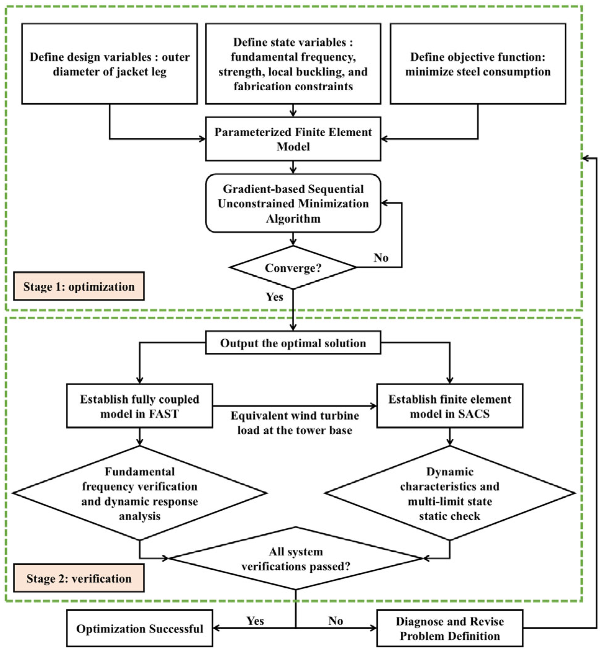
This study develops a systematic design methodology that integrates structural optimization with high-fidelity verification to achieve an optimal balance between lightweight objectives and structural reliability for OWT jacket structures. The proposed framework, as illustrated in Figure 1, establishes a systematic process comprising two phases: gradient-based parameter optimization and system-level performance verification.
The initial phase conducts parametric optimization through a mathematical framework. The outer diameters of jacket legs serve as the primary design variables, while the fundamental natural frequency, structural strength, local buckling resistance, and fabrication requirements constitute the constraint conditions. The optimization objective is formulated to minimize steel consumption, with a parameterized finite element model enabling automated design updates. A gradient-based sequential unconstrained minimization algorithm drives the iterative optimization process until convergence criteria are satisfied, yielding an initial optimal design solution.
The subsequent verification phase subjects this optimized design to comprehensive system-level assessment through dual-path analysis pathways. A fully coupled aero-hydro-servo-elastic model implemented in FAST evaluates dynamic performance characteristics, including fundamental frequency validation and dynamic response analysis. Simultaneously, the equivalent wind turbine loads at the tower base obtained from the FAST simulations are then utilized as input for the detailed finite element model in SACS 14.0, which conducts ultimate limit state checks according to offshore standards. This dual-path verification approach provides complementary insights into the structural performance under environmental conditions.
The proposed framework establishes a systematic methodology that integrates structural optimization with validation. This approach addresses the fundamental challenge of balancing structural lightweight objectives with safety in OWT design. As a two-stage process that utilizes system-level performance feedback for post-optimization verification, the methodology effectively bridges the critical gap between theoretical optimization outcomes and practical structural reliability.

2.2. Gradient-Based Sequential Unconstrained Minimization Algorithm

This study employs a gradient-based sequential unconstrained minimization technique to solve the constrained optimization problem. The methodology systematically transforms the original constrained problem into a sequence of unconstrained subproblems through penalty function formulation, enabling efficient convergence to feasible solutions.
The optimization problem is formally defined as follows. The design variable vector is expressed as:
X = x 1 ,   x 2 ,   x 3 , ,   x n
where n denotes the total number of design variables, each constrained by lower and upper bounds:
x i _ x i x i ¯ ,   i = 1 , 2 , 3 , , n
The objective function to be minimized is formulated as:
min f = f X
Subject to behavioral constraints represented by state variables:
w i _ w i X w i ¯ ,   i = 1 , 2 , 3 , , m
where w i ( X ) represents the state variables; w i _ and w i ¯ are their corresponding lower and upper bounds; and m indicates the number of state constraints.
To handle the constrained optimization problem, an exterior penalty function method is adopted, transforming the problem into an unconstrained formulation. The augmented objective function is constructed as:
Q X , q = f f 0 + i = 1 n P x x i + q i = 1 m P w w i
where P x and P w denote the penalty functions for design variable and state variable, respectively; f 0 is a reference value for objective normalization, which is the mass value of the initial design in this study; and q represents the response surface parameter that controls the penalty weight, and q is increased sequentially, starting from an initial value of 0.1 and multiplied by a factor of 10 after each sub-problem convergence.
The iterative optimization process follows the update rule:
x j + 1 = x j + s j d j
where s j is the optimal step size determined by a line search along the search direction d j .
The search direction is computed using gradient information, the gradient calculation in this study is performed using the semi-analytical method.
The convergence is considered achieved when the following criteria are both satisfied.
f i f i 1 τ ,   f i f b τ
where f i represents the current iteration’s objective value; f i 1 the previous iteration’s value; f b the best value obtained historically; and τ the prescribed convergence tolerance, with a value of 1.0 × 10⁻⁴; A global maximum iteration number of 100 is set in this study.
Based on the sensitivity of the objective function to the design variables, the optimal search direction is determined using the partial derivatives of the objective function with respect to these variables. A line search method is then employed to minimize the unconstrained problem, thereby locating the optimal solution.

2.3. Fully Coupled Modeling in FAST

The fully coupled dynamic analysis within the proposed framework is implemented using FAST v8 [26], an aero-hydro-servo-elastic simulation tool developed by the National Renewable Energy Laboratory (NREL). The numerical model employs a hybrid approach that combines multibody dynamics with finite element methods to achieve an optimal balance between computational efficiency and simulation fidelity.
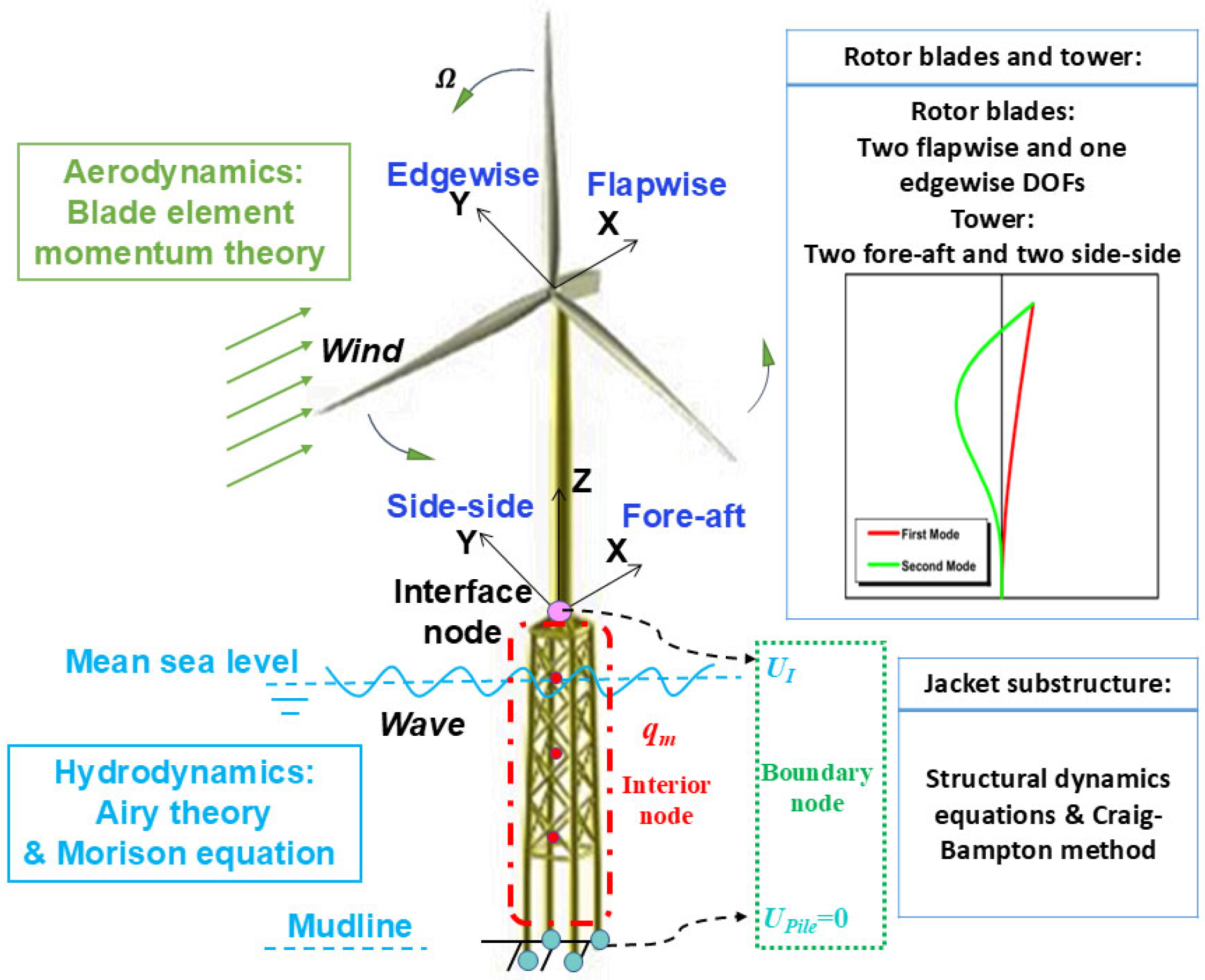
In the FAST framework, the rotor-nacelle assembly (RNA) and tower are modeled using multibody dynamics theory, as shown in Figure 2. The first two flapwise modes and the first edgewise mode of the blades, together with the first two fore-aft and side-to-side bending modes of the tower, are selected as the primary degrees of freedom. The assumed modes method is employed to construct a reduced-order model of the RNA and tower structure. Critically, the ServoDyn control module actively regulates the turbine’s operational state in response to the incoming wind speed, simulating key scenarios such as startup, normal power production, and shutdown. This allows the coupled model to accurately represent the dynamic response of the turbine over the entire operating range.
The system dynamics are governed by Kane’s equations:
F r + F r = 0   r = 1 , 2 , , P
where F r represents the generalized active forces; F r denotes the generalized inertia forces; r is the degree of freedom number; P is the number of degrees of freedom.
Simultaneously, the jacket structure is modeled using linear beam finite elements based on finite element theory. The dynamic behavior is described by the equation of motion:
M u ¨ + C u ˙ + K u = f h y d r o d y n + f e l a s t o d y n + f G
where [ M ] , [ C ] , and [ K ] represent the mass, damping, and stiffness matrices of the support structure’s finite element model, respectively; { u ¨ } , { u ˙ } , and { u } are the acceleration, velocity, and displacement vectors; { f hydrodyn } and { f G } correspond to the hydrodynamic and gravitational load vectors; and { f elastodyn } is the dynamic load vector transferred from the ElastoDyn module to the SubDyn module, encompassing the forces and moments from the RNA and tower dynamics.
The interface between the tower and jacket structure is modeled through a rigid transition piece, ensuring proper load transfer and kinematic compatibility between the multibody dynamic formulation of the superstructure and the finite element representation of the jacket structure. This integrated modeling approach, which incorporates the critical influence of control strategies on the system response, enables comprehensive simulation of the coupled system dynamics, providing critical outputs including the natural frequency and equivalent wind turbine loads at the tower base, which are essential for the subsequent verification of the optimized jacket structure.

2.4. Finite Element Modeling in SACS

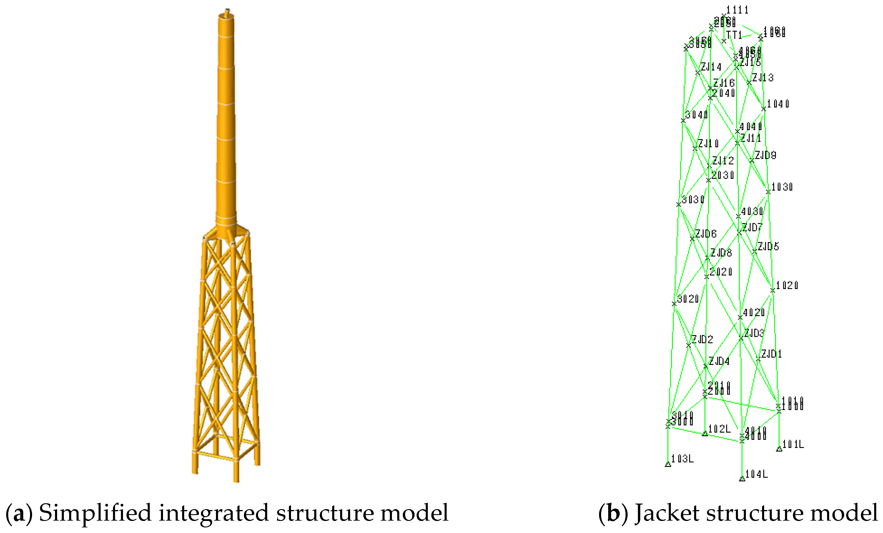
Structural verification of the optimized jacket structure is conducted using the SACS, a specialized finite element analysis software widely employed in the offshore industry for the design and assessment of fixed offshore structures. This verification methodology employs two complementary finite element models to systematically evaluate both dynamic characteristics and structural capacity under various limit states, as illustrated in Figure 3.
For dynamic characterization, a simplified integrated OWT model is developed wherein the RNA is idealized as concentrated mass elements applied at their respective centers of gravity. The tower and jacket structure are discretized using beam elements with appropriate sectional properties, while the pile-soil interaction is represented through nonlinear springs characterized by p-y curves for lateral soil resistance, t-z curves for axial shaft friction, and q-z curves for end-bearing capacity. This modeling approach enables accurate prediction of natural frequencies and mode shapes, providing essential validation of the structure’s dynamic performance against design requirements.
A separate finite element model of the jacket structure is developed for static strength verification. The foundation system incorporates the same advanced pile-soil interaction methodology through p-y, t-z, and q-z curves. The equivalent wind turbine loads at the tower base, derived from fully coupled FAST simulations, are combined with environmental loads including wave, current, and gravitational forces to perform multi-limit state verification of the support structure’s capacity and deformation characteristics.
The structural assessment in SACS follows established offshore design standards, implementing the following verification equations:
U C = σ r σ
where σ r and [ σ ] represent the maximum resultant stress and the allowable stress, respectively; the UC (Unity Check) serves as a criterion for assessing structural strength under combined loading conditions. A lower UC value indicates a higher structural safety margin and greater load-bearing capacity.

3. Structural Optimization of Jacket Structures

3.1. Basic Parameters of Jacket OWT

The case study is based on the well-established NREL 5 MW reference wind turbine [27] and the OC4 jacket substructure [28]. The main parameters of NREL 5 MW reference wind turbine are shown in Table 1. The specific design was adapted for a planned offshore site, resulting in a modified tower and jacket structure. The initial tower section parameters in this study are presented in Table 2:
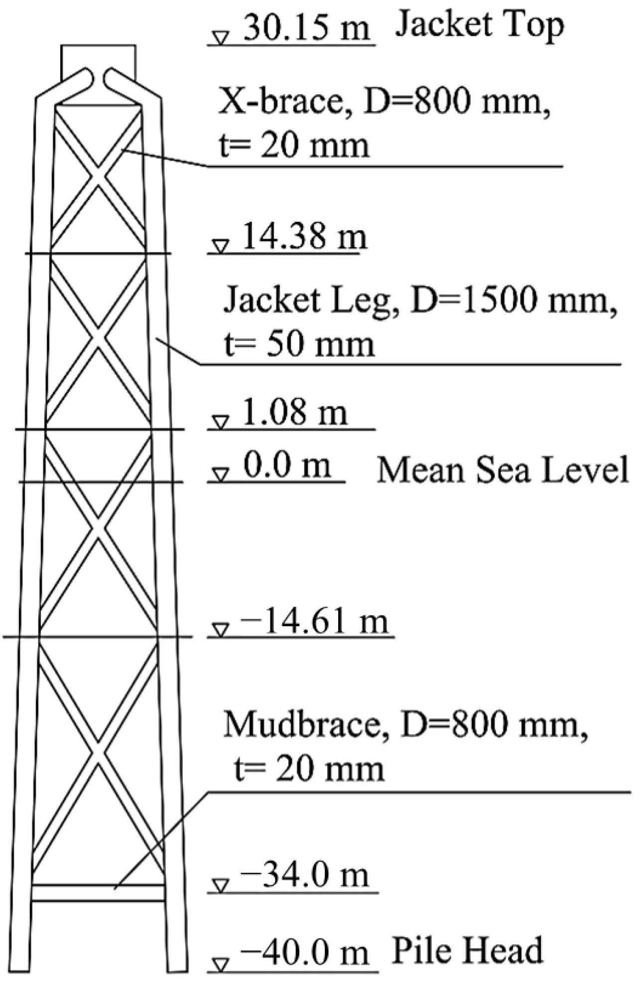
Furthermore, by modifying the member cross-sectional parameters and transition piece configuration of the NREL OC4 jacket structure, the jacket structure in this project was finalized, as illustrated in Figure 4. The densities of the tower and jacket structure in this study are 8500 kg/m3 and 7849 kg/m3, respectively. The specified densities are effective values used for mass estimation, accounting for steel grade, corrosion allowance, coatings, internal appurtenances, following industry practice for preliminary design. Both have elastic moduli of 210 GPa and shear moduli of 80.8 GPa.

3.2. Environmental Parameters and Load Cases

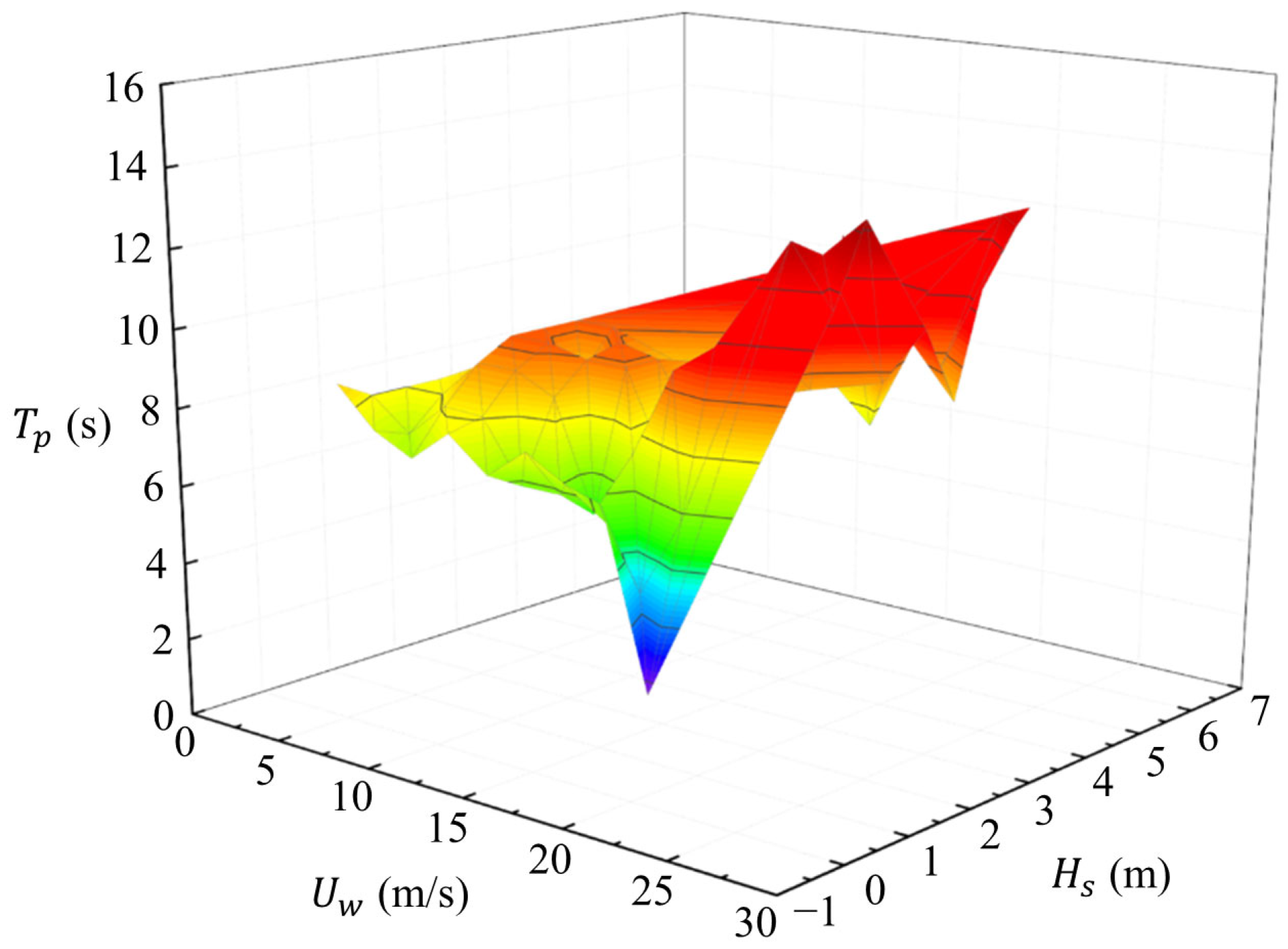
The offshore wind farm is planned to be constructed in a coastal area of Southeast China. The site-specific wind resource parameters and sea state conditions are presented in Table 3. The joint distribution of measured wind speed and wave parameters is shown in Figure 5, where Uw represents the mean wind speed, Hs denotes the significant wave height, and Tp indicates the spectral peak period.
The preliminary design load cases for the jacket structure were selected based on measured metocean data from a specific offshore site, in compliance with the OWT design standard IEC 61400-3-1 [29]. These load cases are summarized in Table 4, where Vin, Vhub, Vout, and V50 represent the cut-in wind speed, wind speed at the hub height, cut-out wind speed, and the 50-year maximum wind speed, respectively; Hs50 denotes the 50-year maximum significant wave height; Tp50 is the 50-year maximum spectral peak period.
The turbulent wind time history was generated using TurbSim [30] with the IEC Kaimal turbulence model, while the random wave elevation time history was simulated by fitting a JONSWAP wave spectrum. Furthermore, the partial load factors and structural importance factors for different limit states were determined according to the OWT structural design standard DNV-OS-J101 [31] and the standard for fixed steel offshore platforms API RP2A-LRFD [32], as presented in Table 5. The simulation duration per random seed was 660 s. For each design load cases, 6 independent random seeds were used to generate wind/wave time series. The time step used in the simulations was 0.05 s.

3.3. Specific Settings for Optimization

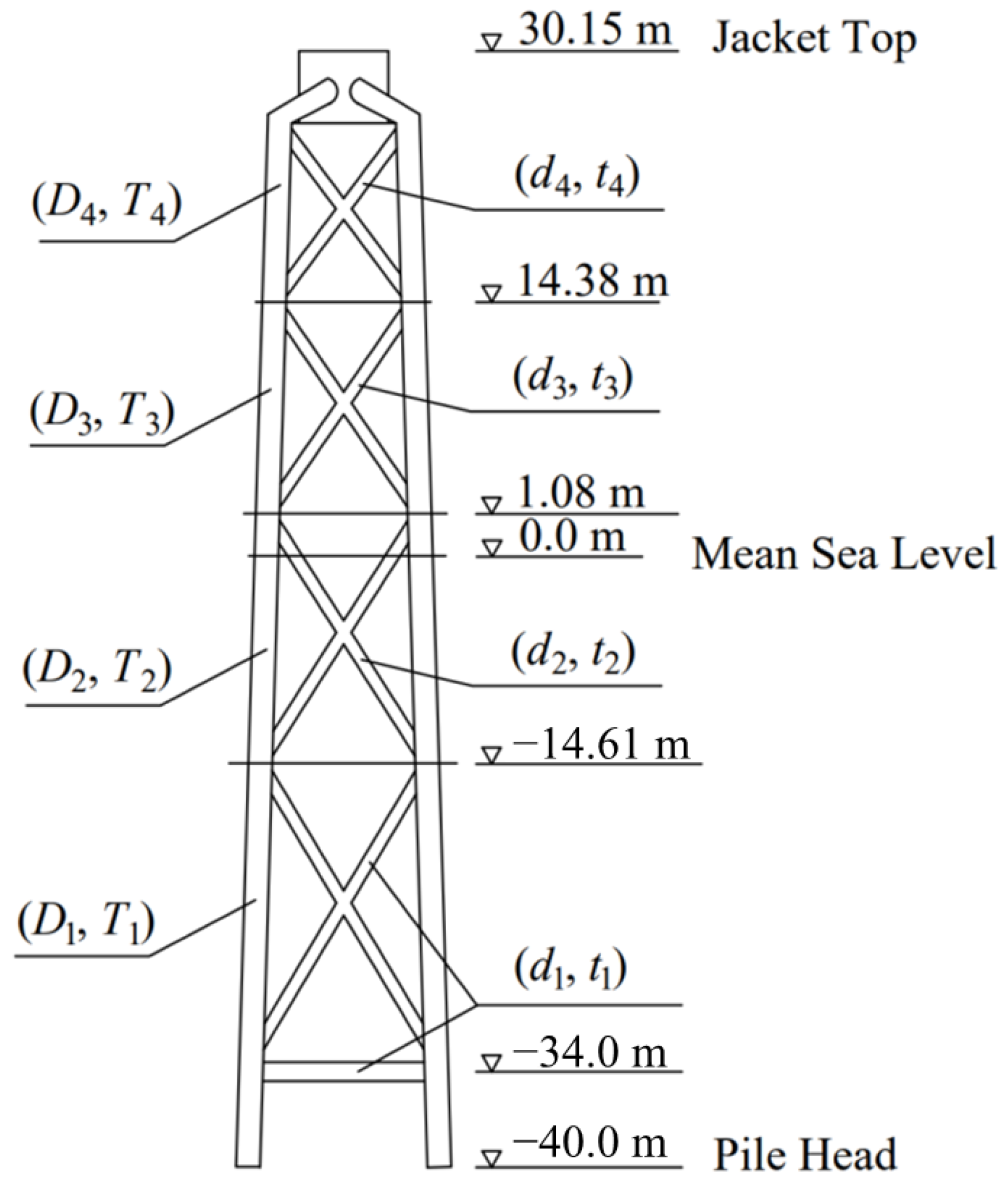
The structural optimization of the jacket structure is formulated with the objective of minimizing steel consumption Wmin, where the outer diameters Di of the jacket legs are defined as the independent design variables, as illustrated in Figure 6. The wall thicknesses of jacket leg Ti, as well as the outer diameters di and wall thicknesses ti of braces, are not independent variables. They are derived parameters calculated from the corresponding outer diameters Di based on Equations (11)–(15). The optimization is subjected to the following constraints to ensure global dynamic performance and structural integrity.
(1)
Global frequency constraint
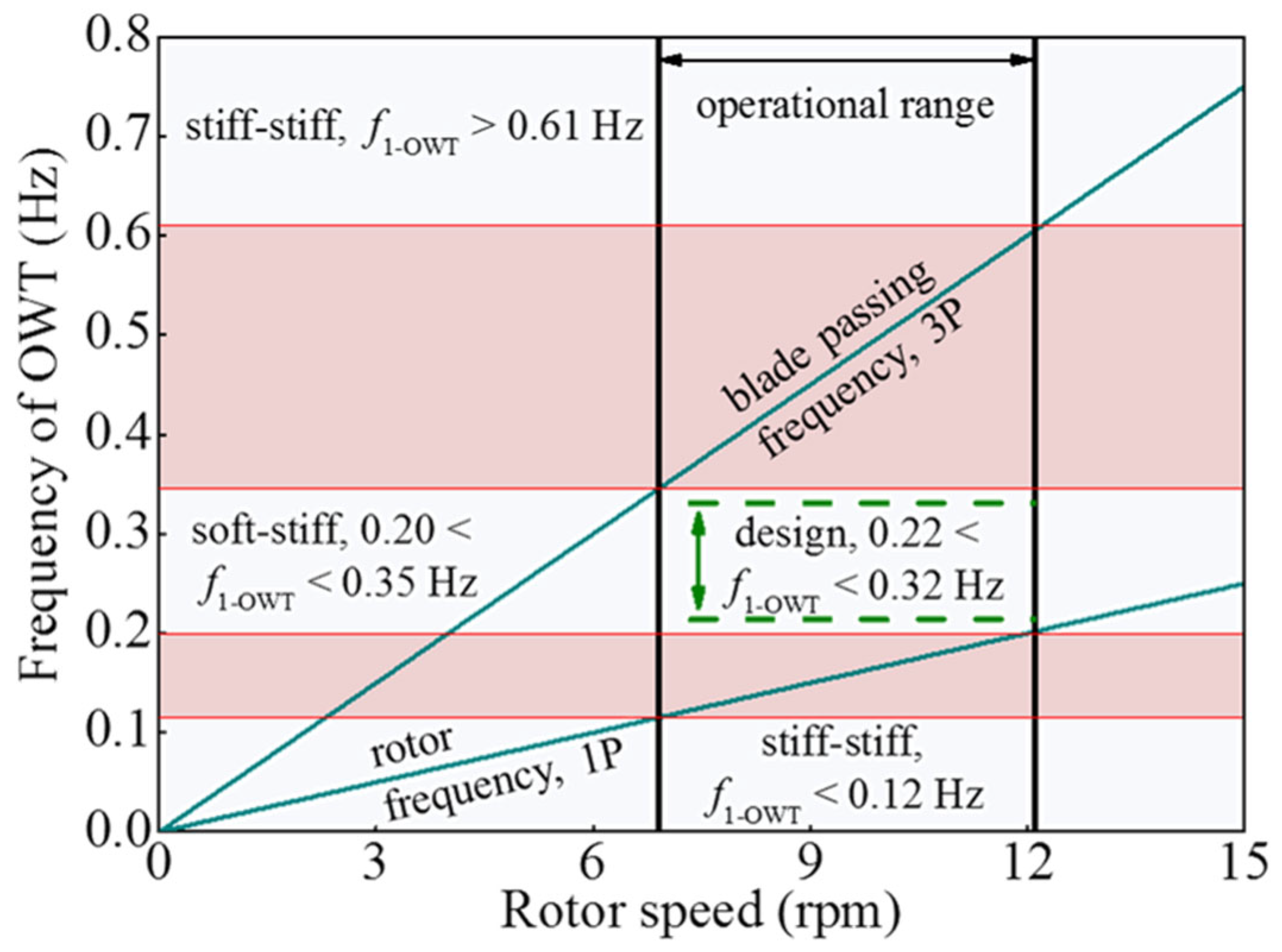
The structural design of jacket structure requires modal analysis of the integrated system comprising the turbine, tower, and jacket structure. The natural frequency of the integrated OWT must be verified to avoid resonance with the 1P (rotor frequency) and 3P (blade passing frequency) ranges. This study conducts frequency design based on the rotor speed range of the NREL 5 MW reference wind turbine, with a cut-in rotor speed of 6.9 rpm and a rated rotor speed of 12.1 rpm, as shown in Table 1. The corresponding 1P frequency ranges from 0.12 Hz to 0.20 Hz, and the 3P frequency ranges from 0.35 Hz to 0.61 Hz, as illustrated in Figure 7. As shown, from both safety and economic perspectives, the appropriate fundamental frequency range for the integrated OWT is determined to be 0.22 Hz < f1-OWT < 0.32 Hz. The lower bound of this target interval, 0.22 Hz, lies above the highest 1P frequency of 0.20 Hz, while the upper bound, 0.32 Hz, remains well below the lowest 3P frequency of 0.35 Hz, maintaining a margin approximately 10%. Consequently, this frequency range is adopted as one of the constraints in the jacket structure optimization problem.
(2)
Material strength constraint
The jacket structure is constructed from Q345 steel with a yield strength σy of 345 MPa. According to the IEC standard [33], the material-related safety factor (γm = 1.30, γc = 1.10) shall be considered. The allowable stress of Q345 steel ([σ] = σy/(γm × γc)   241 MPa), accounting for these safety factors, is adopted as one of the constraints in the jacket structure optimization design. The maximum von Mises stress is limited by the allowable stress [σ].
(3)
Stability and fabrication constraints
The state variables in this optimization must also satisfy the local buckling requirements specified in Equations (11) and (12) and the geometric constraints specified in Equations (13)–(16).
D i 2 T i E m σ y ,   i = 1 , 2 , 3 , 4
d i 2 t i E m σ y ,   i = 1 , 2 , 3 , 4
0.2 d i D i 1.0 ,   i = 1 , 2 , 3 , 4
10 D i 2 T i 50 ,   i = 1 , 2 , 3 , 4
10 d i 2 t i 50 ,   i = 1 , 2 , 3 , 4
1.0 D i 2.0 ,   i = 1 , 2 , 3 , 4
where Di denotes the outer diameter of the ith jacket leg, Ti represents the wall thickness of the ith jacket leg, di indicates the outer diameter of the ith layer of brace, and ti refers to the wall thickness of the ith layer of brace. Additionally, Em and σy correspond to the elastic modulus and yield strength of the Q345 steel material, respectively.

4. Results and Discussion

4.1. Dynamic Performance Validation and Response Analysis Based on Fully Coupled Model

4.1.1. Validation of Dynamic Characteristics

The geometric parameters of the initial and optimized jacket structures are compared in Table 6. According to Equation (17), the optimization achieved a 34% reduction in total steel mass, decreasing from 824 t to 546 t. For the jacket legs, outer diameters were reduced from 1.5 m to 1.3 m with wall thicknesses decreasing from 0.05 m to 0.04 m. This 20% thickness reduction contributed significantly to mass savings while maintaining adequate global stiffness. In addition, the outer diameters of the braces were reduced more substantially from 0.8 m to 0.4 m, while wall thicknesses remained unchanged at 0.02 m. This optimization trend reflects the distinct structural functions of these components. Braces primarily resist axial loads, where capacity can be maintained through diameter reduction, while jacket legs require sufficient bending stiffness to support global structural performance.
M = M o p t M i n i M i n i × 100 %
where M i n i and M o p t represent the parameter values for the initial and optimized steel masses, respectively.
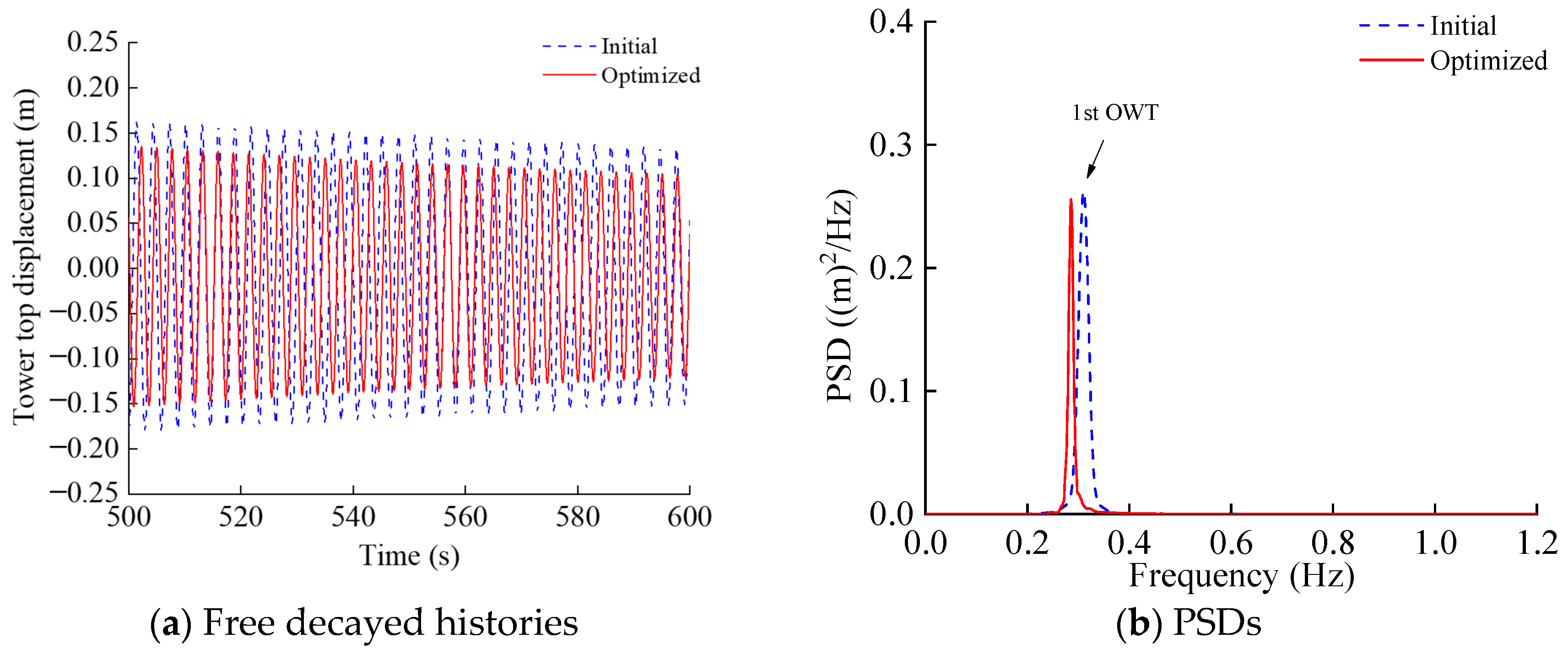
Furthermore, the influence of these geometric modifications on the structural dynamic characteristics was evaluated through free decay tests [34]. An initial displacement of 1.0 m was applied at the tower top in the fore-aft direction. The natural frequency of the OWT based on the fully coupled model was estimated through spectral analysis of the free vibration decay history. The power spectral densities (PSDs) of the tower top displacement are shown in Figure 8.
The fundamental natural frequency was determined to be 0.306 Hz for the initial structure and 0.294 Hz for the optimized. This reduction in natural frequency represents a direct consequence of the decreased structural stiffness resulting from mass reduction. Crucially, both frequencies remain securely within the required soft-stiff frequency band of 0.22–0.32 Hz, effectively avoiding resonance with rotor 1P and 3P excitation frequencies. This validates that the optimization framework achieved significant weight reduction while maintaining essential dynamic performance criteria.

4.1.2. Dynamic Response Analysis Under Typical Design Cases

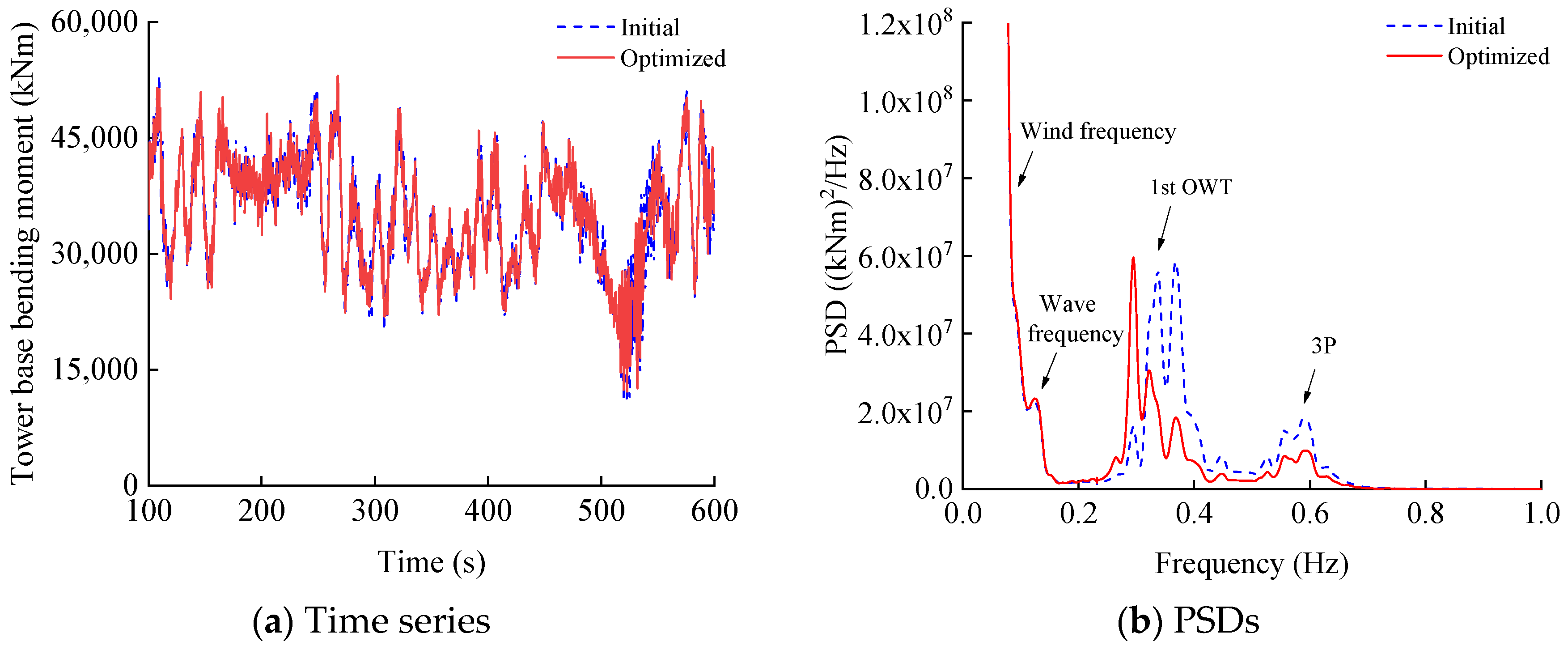
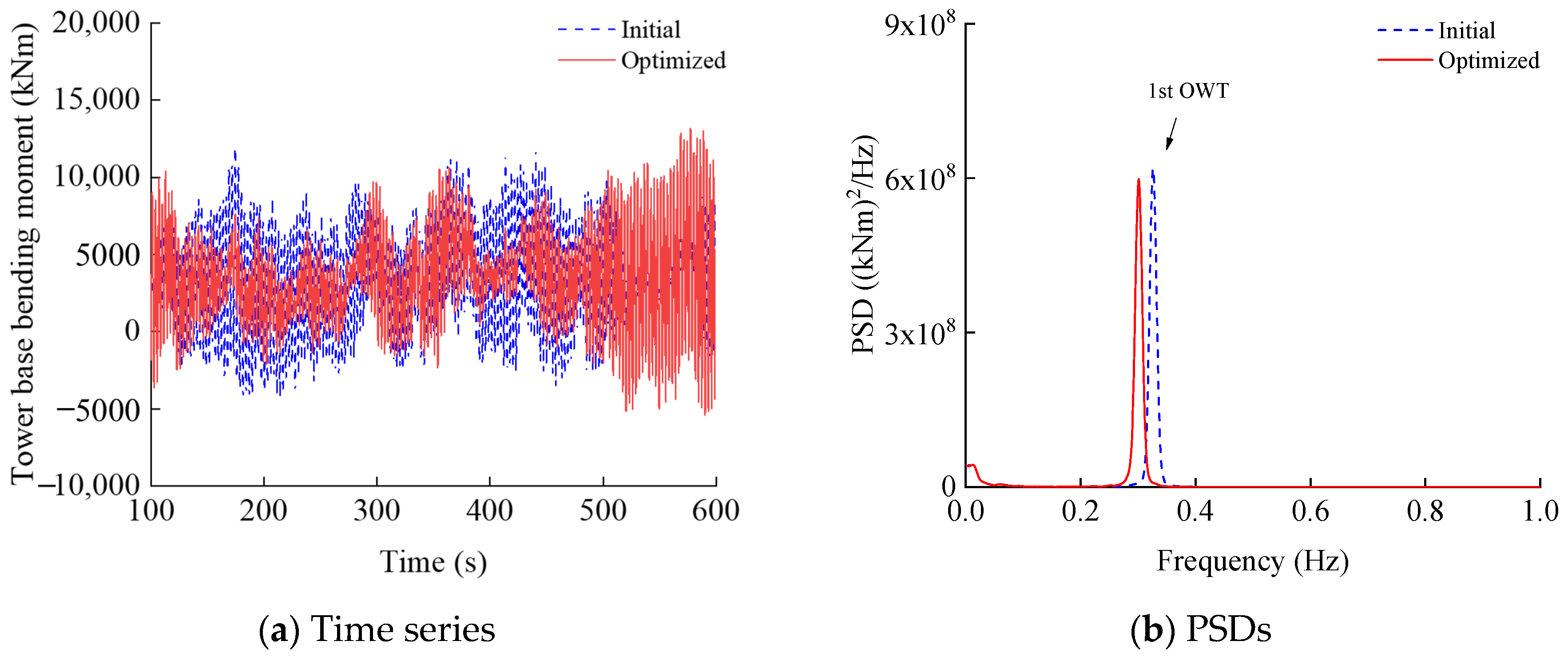
The dynamic response of the OWT was investigated through fully coupled simulations in FAST under two representative design load cases: normal operation (DLC 1.2) and parked condition (DLC 6.4). The time series and PSDs of the bending moment response at the tower base are presented in Figure 9 and Figure 10.
As shown in Figure 9a, the time histories of tower base fore-aft bending moment demonstrate substantial similarity between the initial and optimized structures during normal operation DLC 1.2. This consistency in time-domain response is further elucidated by the spectral analysis in Figure 9b. The response spectrum contains multiple frequency components including wave frequency, fundamental natural frequency, and 3P. The similarity in time-history responses results from the prevailing wind-induced loading under normal operation conditions, which masks the subtle effects of structural modifications.
In contrast, the parked condition DLC 6.4 exhibits more substantial differences in the tower base fore-aft bending moment time histories between the initial and optimized structures, as evidenced in Figure 10a. This increased disparity primarily results from the absence of operational damping with the rotor at standstill, which renders the structural response more sensitive to alterations in natural dynamic characteristics. Figure 10b confirms that the dynamic response under this condition is governed predominantly by the fundamental natural frequency. These findings demonstrate that structural optimization exerts varying influences on dynamic response depending on operational conditions.

4.2. Dynamic Characteristics Validation and Multi-Limit State Assessment Based on Finite Element Model

4.2.1. Model Consistency Verification

Prior to conducting the multi-limit state capacity and deformation assessment, modal analysis was performed using the simplified integrated model established in SACS. Table 7 summarizes the first five natural frequencies obtained for both the initial and optimized structures. Mode 1 and Mode 2 correspond to the first-order global bending modes of the support structure in the fore-aft and side-side directions, respectively. The consistency of these modal frequencies primarily results from the geometric and mass symmetry of the jacket structure in the horizontal plane.
As indicated in Table 7, the fundamental frequency of the optimized structure shows a slight reduction compared to the initial design, a trend that aligns consistently with the findings from the fully coupled model analysis. Importantly, the fundamental frequencies of both satisfy the required frequency constraints. The close agreement between the natural frequencies obtained from the simplified SACS model and those derived from the fully coupled model validates the consistency of the modeling approach and ensures the reliability of subsequent structural verification analyses.

4.2.2. Multi-Limit State Evaluation

Structural capacity and deformation were evaluated under multiple limit states using the established finite element model with designated load cases. The verification results are presented in Table 8, Table 9 and Table 10. All maximum values reported in Table 8, Table 9 and Table 10 were extracted via a two-step procedure: first, the peak value of each response quantity was identified from the full time series of each individual seed; subsequently, the envelope value of these peaks across all seeds within the same DLC was taken as the final representative value for that DLC. To quantify the optimization effects, the variation percentage of key parameters is defined as follows:
Y = Y o p t Y i n i Y i n i × 100 %
where Y i n i and Y o p t represent the parameter values for the initial and optimized structures, respectively.
The optimization outcomes reveal systematic changes in structural performance. According to Table 8, The maximum UC for joint shear decreased substantially by 42.35%, representing a direct and significant improvement in the shear resistance safety margin. Meanwhile, the maximum UCs for member stress and joint strength increased by 3.95% and 22.58%, respectively. These increases indicate a reduced but still acceptable safety margin for these components, as all final UC values remain well below 1.0 and satisfy the design constraints. This indicates that optimization has changed the load transfer mechanism, prioritizing and achieving the goal of enhancing shear performance, while maintaining the integrity of the overall structure and achieving weight reduction.
In addition, the foundation capacity assessment reveals moderate changes in pile performance following structural optimization. As shown in Table 9, the compressive bearing capacity of the piles shows a 1.64% increase, while the tensile bearing capacity demonstrates a 2.27% improvement. These relatively minor variations indicate that the optimization process had limited influence on the fundamental load-bearing characteristics of the pile foundation.
In contrast, more pronounced changes are observed in the deformation characteristics. As illustrated in Table 10, the tangent of the rotation angle at the top of the jacket from 0.00059 to 0.00076, representing a 28.81% change, while the maximum foundation settlement shows an increase from 1.29 cm to 1.47 cm, corresponding to a 13.95% variation. These increased deformation values are consistent with the reduced global stiffness of the optimized jacket structure, yet remain well within the permissible design limits specified for OWT foundations.
The differential impact on foundation capacity and deformation behavior can be attributed to the nature of the optimization approach, which primarily targeted the jacket structure rather than the foundation system. The maintained foundation capacity alongside increased but acceptable deformations demonstrates that the optimization successfully achieved its primary objective of structural weight reduction without compromising the fundamental safety and serviceability requirements of the foundation system.

5. Conclusions

This study has developed a novel two-stage optimization framework for the design of OWT jacket structures, integrating structural optimization with system-level verification. The main conclusions are summarized as follows:
(1)
The optimization framework achieved a 34% reduction in steel mass while maintaining structural performance requirements. This was accomplished through strategic resizing of structural components: jacket leg diameters were reduced from 1.5 m to 1.3 m, and brace diameters from 0.8 m to 0.4 m, with corresponding adjustments to wall thicknesses. The fundamental natural frequency of the optimized OWT was maintained at 0.294 Hz, well within the required soft-stiff frequency band of 0.22–0.32 Hz, ensuring avoidance of resonance with rotor excitation frequencies.
(2)
Dynamic response analysis revealed condition-dependent optimization effects. During normal operation, the similarity in response spectra indicated consistent dynamic behavior, while parked conditions showed more pronounced differences due to increased sensitivity to structural modifications in the absence of operational damping.
(3)
Structural verification confirmed the integrity of the optimized design under multiple limit states. The check results of optimized OWT met the code requirements, with particularly significant joint performance improvements. The variation percentage of joint shear decreased by 42.35%, while the variation percentage of member stress and joint strength increased by only 3.95% and 22.58%, respectively. The bearing capacity of the foundation increases slightly, with all deformations remaining within permissible limits.
(4)
While this research establishes an effective methodology for ULS optimization, it identifies fatigue limit state verification as a crucial area for future development. The proposed framework provides a foundation for advancing support structure design methodologies, offering significant potential for enhancing the cost-effectiveness and reliability of offshore wind energy infrastructure. Future investigations should address fatigue performance integration and expand the methodology’s application to larger turbine capacities and varied site conditions.
(5)
The proposed framework is grounded in deterministic design codes, where load and material safety factors are employed to account for uncertainties and potential nonlinear behaviors. Time-dependent effects such as material nonlinearity, corrosion, and long-term performance degradation are of critical importance and fall within the scope of life-cycle reliability and risk assessment, representing a key direction for future extension of this research framework.

Author Contributions

Conceptualization, J.Y., Y.T. and B.W.; methodology, J.Y. and Y.T.; software, J.Y.; validation, J.Y., Y.T. and B.W.; formal analysis, J.Y.; investigation, J.Y.; resources, Y.T.; data curation, J.Y.; writing—original draft preparation, J.Y.; writing—review and editing, B.W.; visualization, J.Y. and Y.T.; supervision, B.W.; project administration, B.W.; funding acquisition, B.W. All authors have read and agreed to the published version of the manuscript.

Funding

This research work was financially supported by the National Key Research and Development Program of China (Grant NO. 2023YFB4203200). Their financial supports are gratefully acknowledged.

Data Availability Statement

The data presented in this study are available on request from the corresponding author due to the large volume of raw data of jacket structure optimization cannot be fully presented in this manuscript due to space limitations.

Conflicts of Interest

Authors Jiawei Yu and Yujia Tang were employed by the company China Southern Power Grid. Author Bin Wang was employed by the Power China Huadong Engineering Corporation Limited. The remaining authors declare that the research was conducted in the absence of any commercial or financial relationships that could be construed as a potential conflict of interest.

References

  1. Koh, J.H.; Ng, E.Y.K. Downwind offshore wind turbines: Opportunities, trends and technical challenges. Renew. Sustain. Energy Rev. 2016, 54, 797–808. [Google Scholar] [CrossRef]
  2. Hu, L.; Shi, W.; Hu, W.; Chai, W.; Hu, Z.; Wu, J.; Li, X. Short-Term Prediction of Mooring Tension for Floating Offshore Wind Turbines under Typhoon Conditions Based on the VMD-MI-LSTM Method. Renew. Sustain. Energy Rev. 2025, 216, 115606. [Google Scholar] [CrossRef]
  3. Cai, Y.; Zhao, H.; Li, X.; Shi, W.; Xiao, Q. Developing an OpenFOAM solver for coupled aero-hydrodynamic analysis of integrated structure with floating offshore wind turbine and aquaculture net cage. Coast. Eng. 2025, 198, 104720. [Google Scholar] [CrossRef]
  4. Global Wind Energy Council. Global Wind Report 2025; GWEC: Brussels, Belgium, 2025. [Google Scholar]
  5. Damiani, R.; Dykes, K.; Scott, G. A comparison study of offshore wind support structures with monopiles and jackets for US waters. In Proceedings of the Science of Making Torque from Wind (TORQUE 2016), Munich, Germany, 5–7 October 2016; IOP Publishing: Bristol, UK, 2016; Volume 753, p. 092003. [Google Scholar]
  6. Arshad, M.; O’Kelly, B. Global status of wind power generation: Theory, practice, and challenges. Int. J. Green Energy 2019, 16, 1073–1090. [Google Scholar] [CrossRef]
  7. Hahn, M.; Gilman, P. Offshore Wind Market and Economic Analysis; U.S. Department of Energy: Burlington, VT, USA, 2013.
  8. PwC. Offshore Wind Cost Reduction Pathways Study; PwC: London, UK, 2012. [Google Scholar]
  9. Willows, C.; Valpy, B. Approaches to Cost-Reduction in Offshore Wind; BVG Associates: Swindon, UK, 2015. [Google Scholar]
  10. Bendsøe, M.P.; Kikuchi, N. Generating optimal topologies in structural design using a homogenization method. Comput. Methods Appl. Mech. Eng. 1988, 71, 197–224. [Google Scholar] [CrossRef]
  11. Deaton, J.D.; Grandhi, R.V. A survey of structural and multidisciplinary continuum topology optimization: Post 2000. Struct. Multidiscip. Optim. 2014, 49, 1–38. [Google Scholar] [CrossRef]
  12. Zhang, C.; Long, K.; Zhang, J.; Lu, F.; Bai, X.; Jia, J. A topology optimization methodology for the offshore wind turbine jacket structure in the concept phase. Ocean Eng. 2022, 266, 112974. [Google Scholar] [CrossRef]
  13. Tian, X.; Sun, X.; Liu, G.; Deng, W.; Wang, H.; Li, Z.; Li, D. Optimization design of the jacket support structure for offshore wind turbine using topology optimization method. Ocean Eng. 2022, 243, 110084. [Google Scholar] [CrossRef]
  14. Lee, Y.-S.; González, J.A.; Lee, J.H.; Kim, Y.I.; Park, K.; Han, S. Structural topology optimization of the transition piece for an offshore wind turbine with jacket foundation. Renew. Energy 2016, 85, 1214–1225. [Google Scholar] [CrossRef]
  15. Kim, H.-S.; Park, B.; Lee, K. 3D topology optimization of fixed offshore structure and experimental validation. J. Ocean Eng. Technol. 2020, 34, 263–271. [Google Scholar] [CrossRef]
  16. Muskulus, M.; Schafhirt, S. Design optimization of wind turbine support structures—A review. J. Ocean Wind Energy 2014, 1, 12–22. [Google Scholar]
  17. Wang, J.; Ren, Y.; Shi, W.; Collu, M.; Vengatesan, V.; Li, X. Multi-Objective Optimization Design for a 15 MW Semisubmersible Floating Offshore Wind Turbine Using Evolutionary Algorithm. Appl. Energy 2025, 377, 124533. [Google Scholar] [CrossRef]
  18. Zheng, S.; Li, C.; Xiao, Y. Efficient optimization design method of jacket structures for offshore wind turbines. Mar. Struct. 2023, 89, 103372. [Google Scholar] [CrossRef]
  19. Chew, K.-H.; Tai, K.; Ng, E.; Muskulus, M. Optimization of offshore wind turbine support structures using an analytical gradient-based method. Energy Procedia 2015, 80, 100–107. [Google Scholar] [CrossRef]
  20. Oest, J.; Sandal, K.; Schafhirt, S.; Stieng, L.E.S.; Muskulus, M. On gradient-based optimization of jacket structures for offshore wind turbines. Wind Energy 2018, 21, 953–967. [Google Scholar] [CrossRef]
  21. Natarajan, A.; Stolpe, M.; Wandji, W.N. Structural optimization based design of jacket type sub-structures for 10 MW offshore wind turbines. Ocean Eng. 2019, 172, 629–640. [Google Scholar] [CrossRef]
  22. Kaveh, A.; Sabeti, S. Structural optimization of jacket supporting structures for offshore wind turbines using colliding bodies optimization algorithm. Struct. Des. Tall Spec. Build. 2018, 27, e1494. [Google Scholar] [CrossRef]
  23. Kaveh, A.; Sabeti, S. Optimal design of jacket supporting structures for offshore wind turbines using CBO and ECBO algorithms. Period. Polytech. Civ. Eng. 2018, 62, 545–554. [Google Scholar] [CrossRef]
  24. Sandal, K.; Latini, C.; Zania, V.; Stolpe, M. Integrated optimal design of jackets and foundations. Mar. Struct. 2018, 61, 398–418. [Google Scholar] [CrossRef]
  25. Haselbach, P.; Natarajan, A.; Jiwinangun, R.G.; Branner, K. Comparison of coupled and uncoupled load simulations on a jacket support structure. Energy Procedia 2013, 35, 244–252. [Google Scholar] [CrossRef]
  26. Jonkman, B.; Jonkman, J. Guide to Changes in FAST v8; National Renewable Energy Laboratory (NREL): Golden, CO, USA, 2016.
  27. Jonkman, J.; Butterfield, S.; Musial, W.; Scott, G. Definition of a 5-MW Reference Wind Turbine for Offshore System Development; National Renewable Energy Laboratory (NREL): Golden, CO, USA, 2009.
  28. Vorpahl, F.; Popko, W.; Kaufer, D. Description of a Basic Model of the “UpWind Reference Jacket” for Code Comparison in the OC4 Project Under IEA Wind Annex 30; Fraunhofer IWES: Bremerhaven, Germany, 2011. [Google Scholar]
  29. EC 61400-1:2019; Wind Energy Generation Systems—Part 1: Design Requirements. International Electrotechnical Commission: Geneva, Switzerland, 2019.
  30. Jonkman, B.; Kilcher, L. TurbSim User’s Guide (Draft Version); National Renewable Energy Laboratory (NREL): Golden, CO, USA, 2012.
  31. DNV-OS-J101:2014; Design of Offshore Wind Turbine Structures. Det Norske Veritas: Høvik, Norway, 2014.
  32. API RP 2A-WSD:1999; Recommended Practice for Planning, Designing and Constructing Fixed Offshore Platforms—Working Stress Design. American Petroleum Institute: Washington, DC, USA, 1999.
  33. IEC 61400-1:2005; Wind Turbines—Part 1: Design Requirements for Wind Turbines. International Electrotechnical Commission: Geneva, Switzerland, 2005.
  34. Lu, D.; Wang, W.; Li, X. Experimental Study on Dynamic Characteristics and Vibration Mitigation Strategy of Jacket Offshore Wind Turbines Under Typical Normal Operating and Mechanical Fault Conditions. IEEE J. Ocean. Eng. 2025, 50, 2165–2181. [Google Scholar] [CrossRef]
Figure 1. Schematic of the two-stage optimization framework.
Energies 19 00747 g001
Figure 2. Fully coupled model of jacket OWT established in FAST v8.
Energies 19 00747 g002
Figure 3. Numerical simulation model in SACS.
Energies 19 00747 g003
Figure 4. Geometries of jacket structure.
Energies 19 00747 g004
Figure 5. Measured joint distribution of winds and waves.
Energies 19 00747 g005
Figure 6. Schematic of optimized parameters.
Energies 19 00747 g006
Figure 7. Campbell diagram of NREL 5 MW benchmark wind turbine [27].
Energies 19 00747 g007
Figure 8. Free decayed histories and PSDs of the tower top displacement of the initial and optimized jacket OWT.
Energies 19 00747 g008
Figure 9. Time series and PSDs of the tower base fore-aft bending moment of the initial and optimized jacket OWT (DLC 1.2).
Energies 19 00747 g009
Figure 10. Time series and PSDs of the tower base fore-aft bending moment of the initial and optimized jacket OWT (DLC 6.4).
Energies 19 00747 g010
Table 1. General properties of the NREL 5 MW reference wind turbine [27].
ParametersValue
Rating5 MW
Rotor orientation, configurationUpwind, three blades
ControlVariable speed, collective pitch
Rotor, hub diameter126 m, 3 m
Hub height90 m
Cut-in, rated, cut-out wind speed3 m/s, 11.4 m/s, 25 m/s
Rotor mass110,000 kg
Nacelle mass240,000 kg
Tower mass249,718 kg
Cut-in, rated rotor speed6.9 rpm, 12.1 rpm
Table 2. Section parameters of the tower in this study.
Segment IDBottom Elevation
(m)
Top Elevation
(m)
Bottom Outer Diameter
(m)
Top Outer Diameter
(m)
Thickness
(m)
P130.15032.1505.3705.3180.030
P232.15042.1505.3185.0820.028
P342.15054.1505.0824.8000.024
P454.15064.1504.8004.5650.022
P564.15074.1504.5654.3290.020
P674.15083.1504.3294.1180.030
P783.15088.1504.1184.0000.030
Table 3. Environmental parameters.
ParametersValue
Extreme wind speed with a recurrence period of 50 years47.9 m/s
Significant wave height with a recurrence period of 50 years10.05 m
Peak spectral period with a recurrence period of 50 years14.73 s
Annual average current velocity (middle current)0.60 m/s
Current velocity with a recurrence period of 50 years (middle current)1.62 m/s
Table 4. Design load cases.
Load CasesWind ConditionsWave ConditionsSea Current ConditionsDesign Situation
DLC 1.2Normal turbulence model
Vin < Vhub < Vout
Normal sea state
Joint probability distribution of
Hs, Tp, Vhub
Power
production
DLC 1.3Extreme turbulence model
Vin < Vhub < Vout
Normal sea state
Hs = E[Hs|Vhub]
Normal current model
DLC 6.2Extreme turbulence model
Vhub = 0.95 V50
Extreme sea state
Hs = 1.09 Hs50, Tp50
Extreme current modelParked
DLC 6.4Normal turbulence model
Vhub < 0.7 V50
Normal sea state
Joint probability distribution of
Hs, Tp, Vhub
Table 5. Partial load factors and structural importance factors.
Limit StatePartial Load FactorsStructural Importance Factors
Wind Turbine LoadWave LoadOcean Current LoadDead Weight
Ultimate limit state (ULS)1.351.351.351.01.1
Serviceability limit state (SLS)1.01.01.01.01.1
Table 6. Optimization results of jacket structure design variables.
ParameterInitial DesignOptimized Design
D1 (m)1.51.3
D2 (m)1.51.3
D3 (m)1.51.3
D4 (m)1.51.3
T1 (m)0.050.04
T2 (m)0.050.04
T3 (m)0.050.04
T4 (m)0.050.04
d1 (m)0.80.4
d2 (m)0.80.4
d3 (m)0.80.4
d4 (m)0.80.4
t1 (m)0.020.02
t2 (m)0.020.02
t3 (m)0.020.02
t4 (m)0.020.02
Steel mass (t)824546
Table 7. Comparison of natural frequencies of OWTs before and after optimization.
Mode12345
Frequency (Hz)Initial0.3040.3041.0221.0221.556
Optimized0.2910.2911.0141.0141.545
Table 8. Capacity assessment of jacket members and tubular joints.
ParameterMaximum UC ValueAllowed
Value
Requirement
Satisfaction
InitialOptimized Y
Member stress0.760.793.95%1YES
Joint shear0.850.49−42.35%
Joint strength0.620.7622.58%
Table 9. Capacity assessment of pile foundation.
ParameterMaximum UC ValueAllowed
Value
Requirement
Satisfaction
InitialOptimized Y
Compressive bearing capacity0.610.621.64%1YES
Tensile bearing capacity0.440.452.27%
Table 10. Deformation assessment of jacket foundation.
ParameterMaximum ValueAllowed
Value
Requirement
Satisfaction
InitialOptimized Y
Tangent of the rotation angle at the top of the jacket0.000590.0007628.81%0.004YES
Maximum settlement of foundation (cm)1.291.4713.95%10
Disclaimer/Publisher’s Note: The statements, opinions and data contained in all publications are solely those of the individual author(s) and contributor(s) and not of MDPI and/or the editor(s). MDPI and/or the editor(s) disclaim responsibility for any injury to people or property resulting from any ideas, methods, instructions or products referred to in the content.