1. Introduction
Gas hydrates are cage-like crystalline compounds formed by water and methane under specific temperature and pressure conditions, occurring in seafloor or permafrost sediments. With vast reserves and minimal environmental impact, they represent a key direction for future energy transition. However, hydrate decomposition is significantly influenced by reservoir structural characteristics, and improper extraction can trigger disasters such as wellbore instability and submarine landslides [
1]. Current research predominantly focuses on macroscopic mechanical behavior, while our understanding of the microstructure-decomposition coupling mechanism around wells remains incomplete [
2].
The core mechanism by which reservoir structure characteristics near hydrate wells influence decomposition lies in the combined effects of their occurrence patterns, mechanical properties, permeability dynamics, and multi-field coupling interactions [
3]. The occurrence patterns and mechanical property degradation form this foundation. In sediments, hydrates primarily occur as extruded particles (e.g., vein-like, lens-shaped) or pore-invading types (e.g., cemented, pore-filling). Their presence significantly enhances sediment strength and stiffness, but decomposition degrades mechanical properties, reducing shear strength in surrounding soils and potentially triggering differential settlement or subsea pipeline instability. For instance, after cemented hydrate decomposition, reduced inter-particle cohesion is the primary cause of strength loss. Moreover, dynamic permeability evolution directly correlates with decomposition efficiency. Hydrate-filled pores reduce permeability, while post-decomposition porosity increases but heterogeneity intensifies, complicating flow pathways. Pressure reduction methods prioritize hydrate decomposition, promoting sustained surrounding breakdown, whereas thermal shock methods may cause significant permeability decline due to secondary hydrate formation. Additionally, hydrate formations exhibit extreme stress sensitivity; the temperature reduction caused by endothermic decomposition helps mitigate this sensitivity. Indeed, multiphase coupling is central to this complexity. The extraction process involves thermal–mechanical–fluid–chemical multiphase interactions. For instance, excessively rapid pressure reduction may trigger hydrate regrowth, necessitating a balance between efficiency and stability. Thermal stimulation requires extended shut-in periods to mitigate secondary hydrate effects. The flow of decomposition products (gas, water) within porous media is constrained by pore connectivity, and localized high-pressure zones may exacerbate stress imbalances around the wellbore. In situ characterization techniques like low-field
NMR are crucial for monitoring these dynamic processes [
4].
This study reveals the core mechanism by which reservoir structural features regulate hydrate decomposition—specifically through the dual dominant effects of three factors: hydrate distribution patterns (lamellar versus homogeneous), coupled mechanical responses (such as cohesive strength and creep behavior), and thermo–mechanical–fluid multiphase coupling. The study further quantifies critical thresholds for safe extraction (e.g., gas production rate: 0.15–0.25 kg/m3·s) and establishes a gas production–subsidence correlation model. This fills a gap in understanding heterogeneous reservoir dynamics, providing an actionable scientific basis for risk management and efficient extraction.
2. Experimental Methods
2.1. Experimental Design
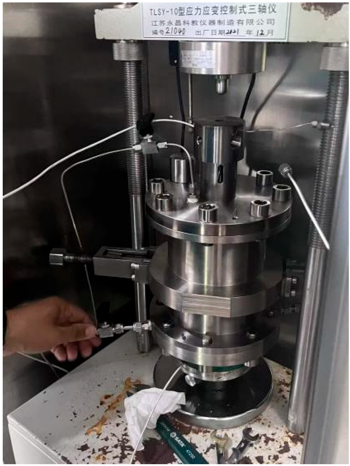
Experiments were conducted in a self-developed physical simulation system for hydrate-bearing sediments. As shown in
Figure 1. This system comprises (a) back-pressure control, (b) confining pressure system, (c) pore pressure system, (d) data acquisition system, (e) high-pressure reactor, (f) axial load control system, and (g) flowmeter, enabling the precise control and monitoring of temperature, pressure conditions, and mechanical states of sediment specimens.
2.1.1. Sample Materials and Granulometry
The sediment skeleton was composed of purified quartz sand (particle density: 2.65 g/cm
3) with a granulometry range of 100–300 μm (D10 = 125 μm, D50 = 210 μm, D90 = 285 μm) measured by laser particle size analysis (Malvern Mastersizer 3000 (Malvern Panalytical Ltd., Worcestershire, United Kingdom)). This sand type was selected for its similarity to natural hydrate-bearing sediments in the South China Sea [
5]. The initial porosity of packed sand was 38.2% ± 1.5%, determined by the water displacement method.
2.1.2. Layered Structure Preparation
Homogeneous Distribution: Quartz sand was uniformly mixed with deionized water to achieve the target initial water saturation (45%), then packed into the reactor in 10 mm layers. Each layer was compacted to a bulk density of 1.62 g/cm3 ± 0.03 g/cm3 to ensure uniform porosity.
Layered Distribution: The specimen (Φ39.1 mm × 120 mm) was designed with two equal-height sublayers (60 mm each). Physical separation was achieved using a porous polyethylene membrane (pore size: 1 μm, thickness: 0.2 mm) between sublayers to prevent mass transfer while maintaining pressure equilibrium. Each sublayer was independently packed with sand–water mixtures to achieve different target hydrate saturations, following the same compaction standard as for the homogeneous specimens.
The experimental workflow comprises four primary steps:
Step a: Sand Preparation, Sand Packing, and Bearing Pressure Fluid Injection—Prepare sedimentary skeletons matching target formation characteristics and apply initial bearing pressure (0.5 MPa).
Step b: Base Installation—Complete specimen mounting and sealing.
Step c: Parameter Setting and Airtightness Check—Configure experimental temperature, pressure, and load parameters while ensuring system integrity.
Step d: Decompression and Data Monitoring—Implement decompression to induce hydrate decomposition while simultaneously monitoring key parameters including gas production rate, cumulative gas yield, and axial displacement.
2.2. Experimental Protocol
2.2.1. Saturation Achievement
Hydrate saturation (Sh) was controlled by adjusting the initial water saturation of the sediment. Based on the stoichiometric ratio of methane hydrate (CH4·6H2O), the target water saturation for each sublayer was calculated to achieve the desired Sh. For example,
To obtain Sh = 10% in a sublayer: initial water saturation = (molar mass of water × Sh)/(molar mass of hydrate) × 100% = (108 × 10%)/124 × 100% ≈ 8.7%.
After packing, methane gas (purity: 99.99%) was injected into the reactor to a pore pressure of 10 MPa. The system was cooled to 1 °C (±0.5 °C) and maintained for 72 h to ensure complete hydrate formation.
2.2.2. Saturation Measurement
Hydrate saturation was verified using a combination of low-field NMR (NMI20-015V-I, resonance frequency: 20 MHz (Suzhou Niumag Analytical Instrument Corporation, Suzhou, China)) and gravimetric methods:
- (1)
NMR Method: T2 relaxation spectra were used to quantify the pore space occupied by hydrates (hydrate-bearing pores show shorter T2 relaxation times than water-filled pores).
- (2)
Gravimetric Method: The mass change in the specimen before and after hydrate formation was measured (accounting for methane consumption). The mass of formed hydrate was calculated as m_hydrate = (m_final − m_initial) × (molar mass of hydrate/molar mass of methane).
- (3)
Final Sh Calculation: Sh = (m_hydrate/(ρ_hydrate × V_pore)) × 100%, where ρ_hydrate = 0.91 g/cm3 and V_pore = porosity × specimen volume. The average of NMR and gravimetric results was taken as the final Sh, with a measurement error of ±1.2%.
2.3. Experimental Results
2.3.1. Analysis of Strain–Time (Creep) Mechanical Characteristics
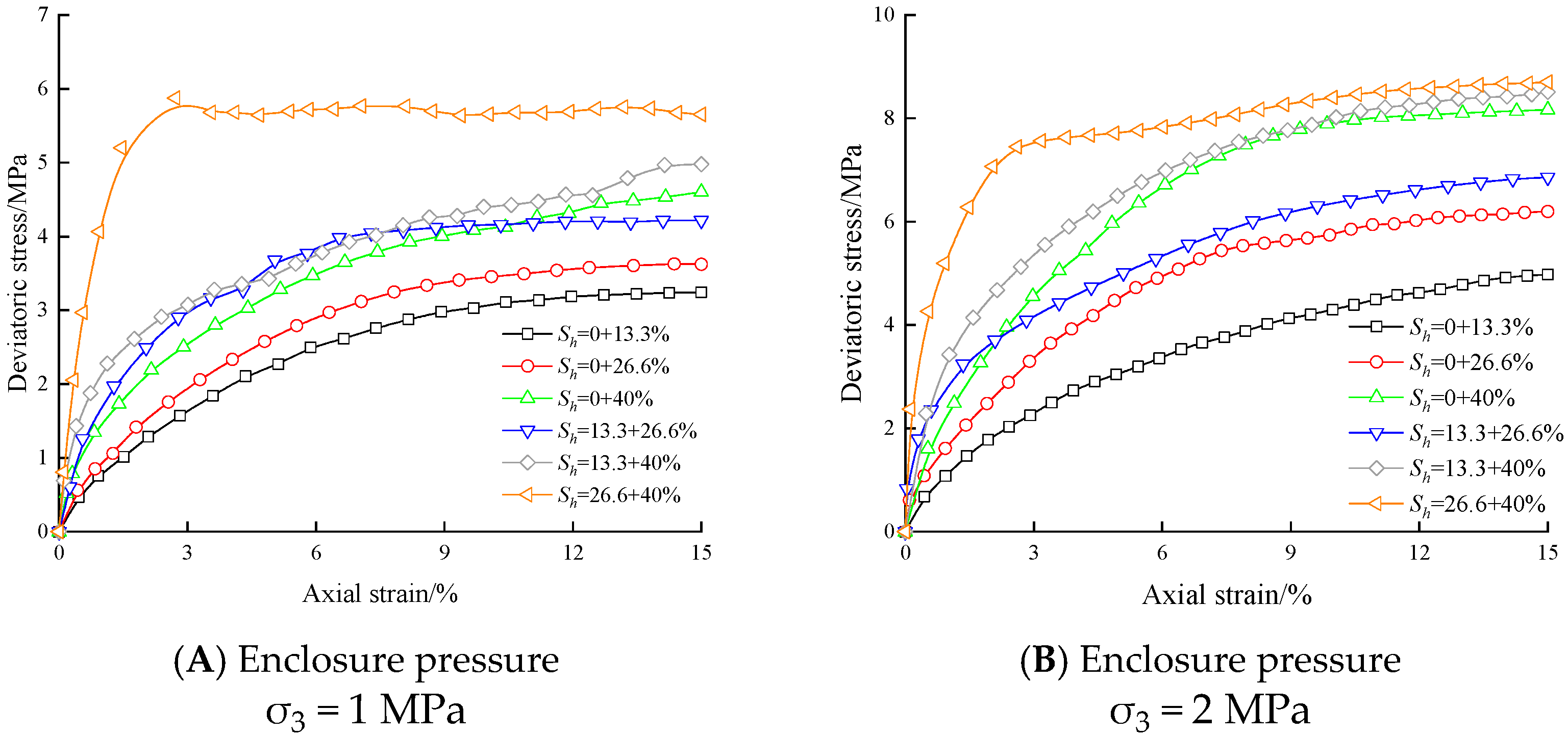
“Based on triaxial creep test results under homogeneous hydrate distribution conditions, at high hydrate saturation, sediments exhibit creep-resistant brittleness characterized by low steady-state creep rates and susceptibility to sudden instability”. On the other hand, at low saturation levels, the sediment exhibits enhanced cumulative plastic creep behavior with higher steady-state creep rates. As hydrate saturation increases, the creep characteristics transition from continuous deformation accumulation (corresponding to original strain hardening) to accelerated creep failure (corresponding to original strain softening). The strain–time (creep) relationship curve for sediments under layered hydrate distribution is shown in
Figure 2. The figure indicates that under layered hydrate distribution, high-saturation sediment sublayers enhance the long-term bearing capacity limit and reduce total creep deformation, while low-saturation sediment sublayers cause rapid strain growth within short timescales (early creep) [
6]. When low-saturation sediment sublayers are present, strain increases rapidly during the early creep stage, resulting in a lower long-term bearing capacity [
7]. Conversely, high-saturation sediment sublayers suppress early creep deformation, slow strain growth, and enhance long-term creep resistance.
Under fixed specimen dimensions (
Φ39.1 mm × 120 mm), the average hydrate saturation (
S_h) in sediments is defined as the weighted average of the saturations in the upper and lower sublayers. Under layered hydrate distribution conditions, the softening–hardening mechanism of sediments is influenced by the hydrate distribution pattern [
8,
9]. Only when both upper and lower sublayers exhibit high hydrate saturation (
S_h ≥ 26% at 1 MPa effective confining pressure;
S_h ≥ 40% at 2 Mpa effective confining pressure) does the creep curve exhibit “accelerated instability” (corresponding to original strain softening). If either sublayer (upper or lower) exhibits low saturation, the entire specimen’s creep curve exhibits “continuous deformation accumulation (corresponding to original strain hardening).” Whether the creep curve displays deformation accumulation or accelerated failure characteristics depends on the sublayer with the lowest saturation within the sediment, that is, the creep behavior of the weakest part of the sediment determines the strain–time curve morphology of the entire sediment. This aligns with the mechanical mechanism where sediment creep failure initiates in the weakest sublayer. Given the pronounced heterogeneity in hydrate distribution within actual reservoirs, construction must account not only for weak surfaces like fractures, pores, karst cavities, and bedding planes but also for hydrate distribution’s impact on long-term creep stability.
Layered hydrate distribution accelerates long-term creep deformation, alters failure patterns and softening–hardening mechanisms, and reduces overall bearing capacity, thus impairing reservoir stability. Therefore, for reservoirs with nodular, vein-like, fracture-filled, or layered hydrate distributions, it is crucial to analyze the impact of weak sections and low-saturation sublayers on creep deformation, creep rate, and bearing capacity [
10,
11]. This involves identifying long-term creep-weakened zones caused by non-uniform hydrate distribution and implementing control measures based on the creep characteristics of weak layers and local weakening control theory. During drilling in natural gas hydrate reservoirs, attention must be paid to the long-term creep characteristics of sediments under layered hydrate distribution conditions. This requires optimizing wellbore trajectories and selecting appropriate drilling fluids while considering the impact of reservoir creep mechanics on long-term wellbore stability. During extraction, hydrate recovery must fully account for the creep effects of weak surfaces and low-saturation sublayers, ensuring the effective control of both wellbore stability and long-term reservoir integrity [
12].
2.3.2. Analysis of Creep Deformation Differences Under Layered and Homogeneous Distribution Conditions
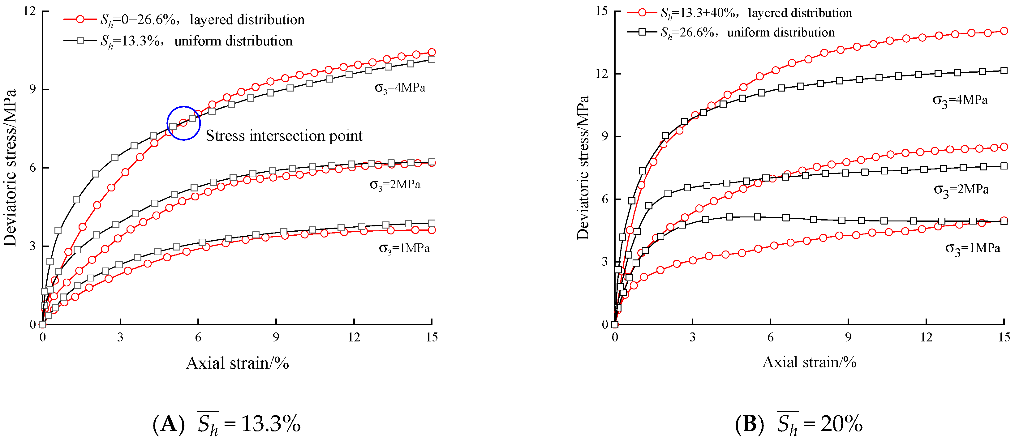
The creep failure mechanism of sediments under layered hydrate saturation distribution differs from that under homogeneous hydrate distribution, exhibiting more complex failure patterns. Sediment layers with varying hydrate saturations exhibit distinct controlling segments in their strain–time (creep) curves across different timescales. As shown in
Figure 3, two curves with identical average hydrate saturation but differing distribution patterns typically intersect beyond the origin—denoting a deformation intersection point—indicating divergent strain growth patterns under varying hydrate distribution states at different time conditions [
13]. When time is less than the deformation intersection time, sediment creep behavior is primarily governed by low-hydrate-saturation sublayers within layered sediments. In
Figure 3A,B, sediments with uniformly distributed hydrates exhibit slower strain growth under identical time conditions, with their curves lying below those of sediments with layered hydrate distributions. When time exceeds the deformation junction time, the sediment creep behavior is primarily governed by sublayers with high hydrate saturation within the layered sediment. This is illustrated in
Figure 3A,B, manifested by the strain–time (creep) curve of sediments with layered hydrate distributions lying below that of sediments with uniformly distributed hydrates under identical time conditions. Furthermore, the long-term bearing capacity limit of the sediment approaches the bearing capacity limit corresponding to the high-saturation sublayer within the sediment, rather than the average of the bearing capacity limits for the two saturation layers [
14,
15].
Under conditions of layered hydrate distribution, sediment particles exhibit varying intergranular cohesion and creep resistance across different hydrate saturation layers. During triaxial creep, as constant stress persists, the weaker strength and bearing capacity of the low-hydrate-saturation sublayer first undergo significant deformation and consolidation, thereby enhancing its creep-resisting bearing capacity until it equals that of the high-saturation sublayer. As loading continues, random creep compression and deformation occur in the weaker sediment sections, causing another saturation sublayer to change. The bearing capacities of the two sublayers then align once more. This process cycles repeatedly until loading ceases, resulting in a cyclical development of compaction–equilibrium–re-deformation within the specimen, ultimately leading to creep failure. During this process, deformation in the sediment occurs primarily in the low-saturation sublayer on short timescales (early creep), while deformation failure on long timescales (late creep) may occur randomly between the high-saturation sublayer and the compacted low-saturation sublayer. Consequently, the creep failure process manifests in the strain–time (creep) relationship as follows: during the early creep stage, the magnitude of strain is primarily determined by the low-saturation sublayers, while the long-term bearing limit is closer to the high-saturation sublayers. Furthermore, the two strain–time (creep) curves under different distribution patterns exhibit deformation intersections.
Through a series of creep experiments, creep characteristic curves for hydrate-containing sediments under different stress conditions were successfully obtained (
Figure 3). The experimental data clearly reveal the synchronous evolution of gas production and axial settlement (displacement) during decompression. Based on this, the study preliminarily identifies the key parameter range governing the critical state of settlement transition, providing indispensable experimental data support for establishing an accurate dynamic correlation model between gas production and settlement.
2.3.3. Hydrate Sediment Failure Strength
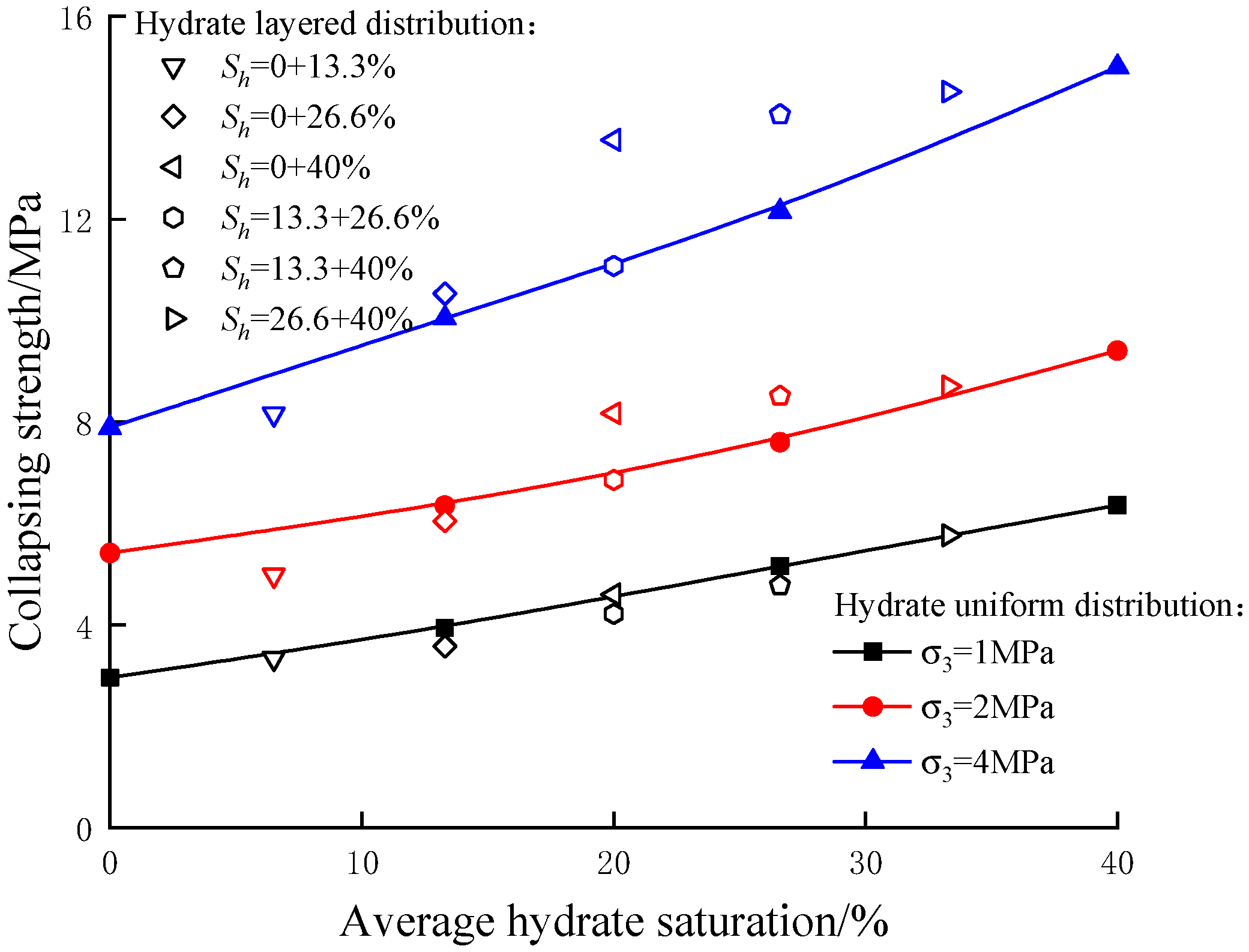
The creep failure strength (long-term bearing capacity limit) of hydrate sediments is defined as the maximum constant stress under which sediments can sustain long-term loading without instability during triaxial creep testing, provided the axial strain remains below 15%.
Figure 4 illustrates the relationship between creep failure strength and hydrate saturation for sediments under different hydrate distribution conditions. Under identical effective confining pressure conditions, the creep failure strength of sediments increases with higher hydrate saturation and is influenced by the distribution pattern of hydrates within the sediment [
16]. At equivalent average hydrate saturations, sediments with layered hydrate distribution exhibit significantly different creep failure strengths compared to those with uniformly distributed hydrates. Under identical effective confining pressure conditions, the creep failure strength shows an approximately linear relationship with hydrate saturation.
Hydrates act as a cementing agent for sediment particles. Consequently, as hydrate saturation increases, cementation strengthens, effectively inhibiting relative particle sliding and creep deformation, thereby enhancing the sediment’s creep failure strength. Under layered hydrate distribution, sediment layers with different hydrate saturations exhibit varying cementation effects and distinct creep resistances. Since creep instability initiates in sediment weak points, creep failure strength is influenced by hydrate distribution patterns. Under identical hydrate saturation conditions, the creep failure strength of sediments significantly increases with rising effective confining pressure. As effective confining pressure rises, overcoming greater frictional resistance for relative particle sliding, rotation, and overriding adjacent particles inhibits lateral creep deformation. This requires increased energy expenditure to induce creep instability in the specimen, manifesting as enhanced creep failure strength [
17].
2.3.4. Cohesion and Internal Friction Angle of Hydrate Sediments
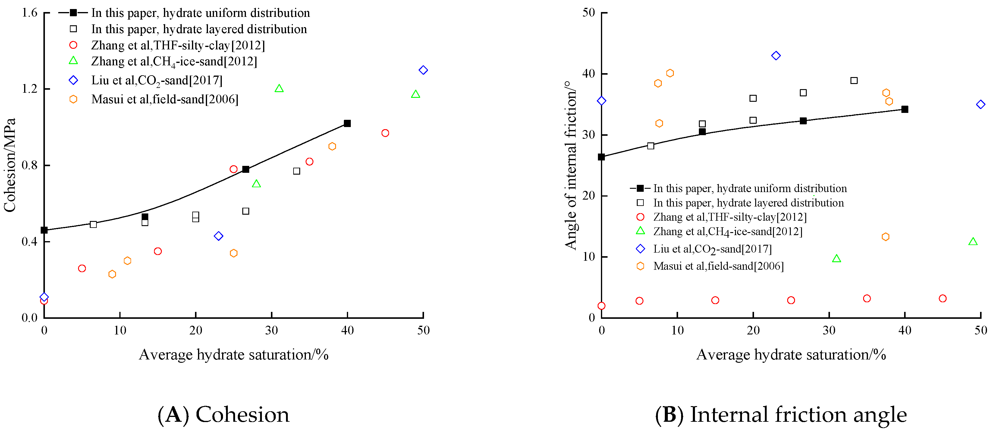
The creep strength indicators (creep cohesion and creep internal friction angle) of hydrate-containing sediments at different hydrate saturations are shown in
Figure 5. The creep cohesion of hydrate deposits (reflecting the cohesive resistance to creep between particles under long-term loading) increases significantly with rising hydrate saturation. Under conditions of uniform hydrate distribution, the creep cohesion of deposits increases from 0.42 MPa to 1.02 Mpa, approaching a 2.5-fold increase. Under conditions of layered hydrate distribution, the creep cohesion of the sediment increased from 0.49 Mpa to 0.77 Mpa. The creep internal friction angle of hydrate deposits (reflecting the anti-creep capability of inter-particle friction under long-term loading) increases with hydrate saturation. Under uniform hydrate distribution, the creep internal friction angle increased from 26.4° to 34.2°, while under layered hydrate distribution, it increased from 28.2° to 38.9°.
This indicates that within a certain range, hydrates enhance the long-term creep resistance of hydrate deposits by increasing the cementation strength between sediment particles, thereby boosting creep cohesion. Conversely, the creep internal friction angle is less significantly influenced by hydrate saturation. Furthermore, the trend in sediment creep cohesion closely resembles that of creep failure strength in hydrate sediments, indicating similar mechanisms governing hydrate saturation effects on both properties. Concurrently, creep internal friction angle results fall within reasonable ranges, validating experimental reliability [
18].
At the same average hydrate saturation, the creep internal friction angle of sediments under layered hydrate distribution is higher than that under uniform hydrate distribution, with the difference increasing as average saturation rises. The creep cohesion of sediments under layered hydrate distribution is lower than that under uniform hydrate distribution. Under layered hydrate distribution, creep instability initiates at weak planes (points). Since hydrate cementation is relatively weaker in low-saturation sublayers, sediment creep cohesion is more significantly influenced by these sublayers. Consequently, sediment creep cohesion under layered hydrate distribution is lower than that under the same average saturation.
In summary, the creep cohesion and creep internal friction angle of hydrate sediments are influenced by hydrate distribution patterns and exhibit distinct trends with increasing average saturation. The creep cohesion and creep internal friction angle of sediments play a crucial role in predicting the long-term creep strength parameters of hydrate sediments. Therefore, predicting the long-term stability of natural gas hydrate reservoirs necessitates consideration of hydrate distribution within sediments [
19].
Figure 5.
Creep cohesion and internal friction angle of hydrate sediments [
20,
21,
22].
Figure 5.
Creep cohesion and internal friction angle of hydrate sediments [
20,
21,
22].
3. Discussion
Key parameters obtained from the experiments (including but not limited to critical gas production rate, critical saturation, critical pore pressure, and critical effective stress) will provide calibration references for subsequent particle-scale discrete element simulations and support the reliability of macro-scale formation stability analyses using continuous medium models. Based on the physical simulation system for hydrate sedimentation, an innovative experimental study covering the entire hydrate formation–creep–decomposition process was conducted. By simultaneously monitoring the evolution of gas production rate, cumulative gas production, and axial displacement during decompression decomposition, precise ranges for four critical control parameters under sedimentation-induced critical state were obtained for the first time—critical gas production rate: 0.15–0.25 kg/m3·s, critical saturation: 25–35%, critical pore pressure: 2.5–3.5 MPa, and critical effective stress: 1.8–2.5 MPa.
3.1. Interpretation of Experimental Results and Physical Mechanisms
The experimental results reveal that hydrate distribution patterns (layered vs. homogeneous) exert a significant regulatory effect on sediment creep behavior and mechanical properties, which can be attributed to three core physical mechanisms.
3.1.1. Sublayer Dominance Effect
Under layered distribution, low-saturation sublayers act as “weak links” dominating early creep deformation (0–10 h). This is because low hydrate saturation leads to insufficient cementation between sediment particles, resulting in higher intergranular sliding and plastic deformation. In contrast, high-saturation sublayers provide structural support, enhancing long-term bearing capacity by inhibiting particle rearrangement and creep localization. This dual-dominance mechanism (low-saturation for short-term strain, high-saturation for long-term strength) explains the deformation intersection phenomenon in
Figure 3.
3.1.2. Cementation–Friction Synergy
Creep cohesion is primarily determined by hydrate cementation strength. In layered sediments, low-saturation sublayers have weaker cementation (15–28% lower than homogeneous sediments), leading to lower overall cohesion. However, physical separation of sublayers and enhanced particle interlocking in high-saturation zones increase frictional resistance, resulting in a 5–12% higher internal friction angle compared to homogeneous sediments [
20,
23].
3.1.3. Gas Production–Settlement Coupling
The positive correlation between cumulative gas production and formation settlement (
R2 = 0.94) indicates that hydrate decomposition alters pore structure and increases effective stress, triggering consolidation [
21]. The critical gas production rate (0.15–0.25 kg/m
3·s) represents the threshold where settlement transitions from stable to accelerated deformation, as excessive gas production causes rapid pore pressure reduction beyond the sediment’s creep resistance.
3.2. Comparison with the Literature Data
The findings of this study are validated and contextualized through a comparison with the key literature, as shown in
Table 1:
3.3. Limitations and Future Work
This study focuses on quartz sand sediments with two-layered distribution; future research should (1) investigate multi-layered and irregular distribution patterns (e.g., vein-like, nodular) common in natural reservoirs; (2) consider the effect of clay content on creep–cohesion relationships; (3) integrate in situ NMR data to visualize pore-scale hydrate decomposition and creep deformation.
3.4. Industry Application Recommendations
(1) Drilling Engineering: For layered hydrate reservoirs, optimize wellbore trajectories to avoid low-saturation sublayers (
Sh ≤ 20%) where possible; if unavoidable, use a 30–45° inclined wellbore to reduce stress concentration on weak sublayers [
14]. Select drilling fluids with dynamic viscosity 15–25 mPa·s and filtration loss ≤5 mL/30 min to balance borehole stability and reservoir protection, considering the 15–28% lower cohesion of layered sediments.
(2) Extraction Operation: Control gas production rate within 0.15–0.25 kg/m
3·s to avoid exceeding the critical settlement threshold; use stepwise decompression (0.1 MPa/min) to match the creep response of low-saturation sublayers [
22]. For reservoirs with layered distribution (e.g., upper
Sh = 15%, lower
Sh = 25%), implement segmented extraction: first extract from high-saturation sublayers (to maintain 30–40% saturation) and then low-saturation sublayers, reducing cumulative deformation by 25–35%.
(3) Reservoir Monitoring:
Deploy fiber optic sensors to monitor axial displacement in real time; set an alarm threshold of 0.1 mm/h (corresponding to 0.35% formation settlement for 50 m formations). Use low-field
NMR to detect changes in hydrate saturation; when the average saturation drops to 25–35% (critical range), adjust extraction parameters to prevent accelerated creep failure [
15,
16].
4. Conclusions
- (1)
Compared to homogeneous hydrate distribution, layered hydrate saturation modifies sediment creep characteristics by 35–50% (long-term creep deformation acceleration) and reduces long-term bearing capacity by 20–35%. The creep softening–hardening mechanism depends on low-saturation zones (Sh ≤ 20%): only when both sublayers have high saturation (Sh ≥ 26% at 1 MPa confining pressure; Sh ≥ 40% at 2 MPa) does accelerated instability occur. For a 1:1 height ratio of high- and low-saturation sublayers, low-saturation sublayers dominate early creep strain (contribution ≥ 70%) within 0–10 h, while long-term bearing capacity approaches that of high-saturation sublayers (deviation ≤ 10%).
- (2)
At the same average hydrate saturation, layered distribution results in a 5–12% higher creep internal friction angle (28.2–38.9°) and a 15–28% lower creep cohesion (0.49–0.77 MPa) compared to homogeneous distribution (friction angle: 26.4–34.2°; cohesion: 0.42–1.02 MPa). Creep cohesion of layered sediments is dominated by low-saturation sublayers (contribution ≥ 65%), while the internal friction angle is mainly influenced by high-saturation sublayers.
- (3)
The critical parameter range for stable hydrate extraction is as follows: critical gas production rate 0.15–0.25 kg/m3·s, critical saturation 25–35%, critical pore pressure 2.5–3.5 MPa, and critical effective stress 1.8–2.5 MPa. Exceeding these thresholds leads to 0.35% or higher formation settlement (for 50 m thick formations), increasing geological hazard risks.
Author Contributions
Conceptualization, Z.L.; Methodology, J.J.; Software, Y.L.; Validation, J.Z.; Formal analysis, B.H. All authors have read and agreed to the published version of the manuscript.
Funding
This research was funded by the Hainan province major science and technology project (ZDKJ2021025).
Data Availability Statement
The original contributions presented in the study are included in the article, further inquiries can be directed to the corresponding author.
Conflicts of Interest
Author Bo Han was employed by the company Jiangsu Zhengdao Ocean Technology Co., Ltd. The remaining authors declare that the research was conducted in the absence of any commercial or financial relationships that could be construed as a potential conflict of interest.
References
- Bian, H.; Zhang, Z.; Li, S.; Pang, S.; Li, Y.; Sun, Y.; Li, X. Mechanisms and challenges of large–scale exploitation of natural gas hydrate in the South China sea. J. Eng. Geol. 2025, 33, 1736–1750. [Google Scholar] [CrossRef]
- Yu, G.; Ou, W.; Wu, X.; Ning, F.; Zhang, L. Research advances on the dissociation dynamics of natural gas hydrates. Bull. Geol. Sci. Technol. 2023, 42, 175–188. [Google Scholar]
- Zhang, Z.; Li, Y.; Bian, H.; Li, S.; Ma, C. Coupled reservoir–wellbore production model and multi–physical field evolution mechanism for natural gas hydrate reservoirs. Acta Geol. Sin. 2025, 99, 3871–3882. [Google Scholar] [CrossRef]
- Sun, J.; Zhao, K.; Liao, B.; Lv, K.; Wang, J.; Liu, J.; Bai, Y.; Wang, R.; Bai, Y. Research progress on drilling fluids for wellbore stabilization in marine natural gas hydrate reservoirs. Nat. Gas Ind. 2025, 45, 1–16. [Google Scholar] [CrossRef]
- Wu, N.; Yang, S.; Zhang, H.; Liang, J.; Wang, H.; Su, X.; Fu, S. Preliminary discussion on gas hydrate reservoir system of Shenhu area, North Slope of South China Sea. In Proceedings of the 6th International Conference on Gas Hydrates ICGH 2008, Vancouver, BC, Canada, 6–10 July 2008. [Google Scholar]
- Lei, L.; Seol, Y. Pore–scale investigation of methane hydrate–bearing sediments under triaxial condition. Geophys. Res. Lett. 2020, 47, e2019GL086448. [Google Scholar] [CrossRef] [Scilit]
- Yu, C.; Sun, B.; Ji, J.; Wang, Z.; Gao, Y.; Chen, L. Study on the Dissociation Characteristics of Methane Hydrate in Clayey Silts. Chem. Eng. Sci. 2022, 252, 117508. [Google Scholar] [CrossRef] [Scilit]
- Miyazaki, K.; Yamaguchi, T.; Sakamoto, Y.; Tenma, N.; Ogata, Y.; Aoki, K. Effect of confining pressure on mechanical properties of sediment containing synthetic methane hydrate. J. Min. Mater. Process. Inst. Jpn. 2010, 126, 408–417. [Google Scholar]
- Li, Y.; Wu, N.; Wang, H.; Ji, Y.; Qi, M.; Liu, C.; Wan, Y.; Chen, M. Multi–field coupling modes during marine natural gas hydrate explotation and its advancements. J. Eng. Geol. 2024, 32, 1355–1366. [Google Scholar] [CrossRef]
- Qin, X.; Lu, C.; Zhang, Z.; Wang, P.; Li, S.; Dong, Y.; Ma, C.; He, Y.; Pang, S. Research progress on thermal–fluid coupling and temperature field regulation in natural gas hydrate production tests in the South China Sea. Acta Geol. Sin. 2024, 98, 3213–3224. [Google Scholar]
- Liu, L.; Li, Y.; Zhang, X.; Luo, D.; Liu, C. Experimental study on gas hydrate system state evolving during depressurization. J. Eng. Geol. 2021, 29, 1916–1925. [Google Scholar] [CrossRef]
- Li, Q.; Cheng, Y.; Zhang, H.; Yan, C.; Liu, Y. Simulating the effect of hydrate dissociation on wellhead stability during oil and gas development in deep water. J. Ocean Univ. China 2018, 17, 35–45. [Google Scholar] [CrossRef] [Scilit]
- Uchida, S.; Klar, A.; Yamamoto, K. Sand production model in gas hydrate–bearing sediments. Int. J. Rock Mech. Min. Sci. 2016, 86, 303–316. [Google Scholar] [CrossRef] [Scilit]
- Li, H.; Zhang, X.; Lu, C.; Xie, P.; Lu, X. Analysis of creep characteristics of hydrate sediments under compressive loading. Mar. Geol. Quat. Geol. 2023, 43, 217–225. [Google Scholar]
- Hu, T.; Wang, H.N.; Jiang, M.J. Analytical approach for the fast estimation of time dependent wellbore stability during drilling in methane hydrate–bearing sediment. J. Nat. Gas Sci. Eng. 2022, 99, 104422. [Google Scholar] [CrossRef] [Scilit]
- Bhandari, R.A.; Cardona, A.; Flemings, B.P.; Germaine, J.T. The geomechanical response of the Gulf of Mexico Green Canyon 955 reservoir to gas hydrate dissociation: A model based on sediment properties with and without gas hydrate. Mar. Pet. Geol. 2024, 167, 107000. [Google Scholar] [CrossRef] [Scilit]
- Norimasa, Y.; Qi, W.; Kazuki, F.; Kajiyama, S.; Nakata, Y.; Hyodo, M. Hydrate dissociation and mechanical properties of hydrate–bearing sediments under local thermal stimulation conditions. Gas Sci. Eng. 2023, 116, 205045. [Google Scholar] [CrossRef] [Scilit]
- Kalacheva, P.L.; Portnyagin, S.A.; Solovyeva, A.S. Research of Formation and Decomposition Processes of Natural Gas Hydrates of Different Composition in Model Stratum Waters of a Bicarbonate–Sodium Type. IOP Conf. Ser. Earth Environ. Sci. 2020, 459, 052069. [Google Scholar] [CrossRef] [Scilit]
- Li, S.; Sun, Y.; Cao, H.; Geng, W.; Chen, W.; Zhang, X.; Zhang, D.; Xu, C.; Chen, Y.; Zhou, Y.; et al. Research progress on natural gas hydrate accumulation in shallow marine layers. Mar. Geol. Quat. Geol. 2025, 45, 120–131. [Google Scholar]
- Zhang, X.H.; Lu, X.B.; Zhang, L.M.; Wang, S.Y.; Li, Q.P. Experimental study on mechanical properties of methane-hydrate-bearing sediments. Acta Mech. Sin. 2012, 28, 1356–1366. [Google Scholar] [CrossRef] [Scilit]
- Liu, Y.; Wang, P.; Yang, M.; Zhao, Y.; Zhao, J.; Song, Y. CO2 sequestration in depleted methane hydrate sandy reservoirs. J. Nat. Gas Sci. Eng. 2018, 49, 428–434. [Google Scholar] [CrossRef] [Scilit]
- Masui, A.; Haneda, H.; Ogata, Y.; Aoki, K. Mechanical properties of sandy sediment containing marine gas hydrates in deep sea offshore Japan. In ISOPE Ocean Mining and Gas Hydrates Symposium; ISOPE: Mountain View, CA, USA, 2007; p. ISOPE-M. [Google Scholar]
- Sun, N.D.; Li, W.P. Natural gas hydrate production technology and outlook of its prospect. Pet. Technol. Forum 2013, 32, 15–19. [Google Scholar]
| Disclaimer/Publisher’s Note: The statements, opinions and data contained in all publications are solely those of the individual author(s) and contributor(s) and not of MDPI and/or the editor(s). MDPI and/or the editor(s) disclaim responsibility for any injury to people or property resulting from any ideas, methods, instructions or products referred to in the content. |