Article

Influence of Harmonic and DC-Bias Coupling on Transformer Energization Inrush Current in Complex Power Grids

1
State Grid Guanyun Power Supply Company, Lianyungang 222000, China
2
Jiangsu Electric Power Company, Nanjing 210024, China
3
State Key Laboratory of Smart Power Distribution Equipment and System, Hebei University of Technology, Tianjin 300401, China
4
Key Laboratory of Electromagnetic Field and Electrical Apparatus Reliability of Hebei Province, Hebei University of Technology, Tianjin 300401, China
*
Author to whom correspondence should be addressed.
Energies 2026, 19(18), 4455; https://doi.org/10.3390/en19184455 (registering DOI)
Submission received: 23 August 2026 / Revised: 12 September 2026 / Accepted: 15 September 2026 / Published: 20 September 2026

Abstract

The methodological innovation of this study is a phase-domain separation-and-recombination framework that maps harmonic voltage to prospective flux, maps controlled quasi-DC winding current to magnetic operating-point displacement, and then resolves their nonlinear interaction through a shared-yoke three-limb model. A reduced nonlinear model informed by the measured major loops of a 50 kVA, 10 kV/400 V, Yyn0 transformer is evaluated over breaker-command angle and residual-flux sweeps. The operating matrix contains a sinusoidal baseline, a 0.15 p.u. negative-sequence second harmonic, a 0.08 p.u. negative-sequence fifth harmonic, their simultaneous application, and single-phase or asymmetric DC-current commands. Peak current, cycle-envelope decay, current total harmonic distortion, negative-sequence ratio, and a fourth-order three-phase current norm distinguish instantaneous from sustained stress. At the 60° command angle, the baseline, harmonic, DC-biased, and combined peaks are 21.30, 32.19, 35.15, and 41.67 A, respectively. Harmonic phase and sequence shift the knee-crossing instant and the dominant limb, whereas differential DC injection compresses one-directional saturation margin. The interaction contrast is interpreted as a model-output non-additivity statistic rather than an independent physical coupling constant. The conclusions are limited to the modeled distorted-source and differential-bias conditions; absolute prediction requires transformer-specific transient validation.

1. Introduction

Transformer energization establishes core flux through the time integral of the applied winding voltage. If residual flux at contact making is incompatible with the prospective periodic flux, the offset can carry the core beyond the knee of its magnetization curve, sharply reducing incremental inductance and drawing a large asymmetric current. The resulting electrodynamic force, bus-voltage depression, vibration, thermal stress, and harmonic-rich differential current can affect insulation life and protection security [1,2]; the broader equipment-reliability implications of repeated electromagnetic and thermal duty are reviewed in [3].
Residual-flux estimation and controlled switching address causal variables before the inrush develops. Brunke and Froehlich derived the theoretical flux-matching condition for controlled switching [4] and then quantified application and breaker-performance requirements [5]. Active residual-magnetism elimination based on energy-storage oscillation provides another means of controlling the initial magnetic state before energization of large power transformers [6]. Chiesa et al. demonstrated the sensitivity of inrush calculation to the saturation characteristic, residual state, source impedance, and breaker timing [7]; a companion study combined laboratory measurements with analytical interpretation of mitigation [8]. Cui et al. tested sequential phase energization [9]. Mitra et al. extended controlled switching to three-phase units [10]. Pan et al. combined prefluxing with controlled switching [11], whereas Pachore et al. minimized a three-phase flux-error objective [12].
The distinction between passive identification and active suppression is important. Hamilton compared harmonic-restraint principles using analytical, recorded, and simulated inrush cases [13]. Raichura and Patel reviewed signal-based discrimination methods and their dependence on core saturation and harmonic content [14]. These methods improve protection security after current appears, whereas active measures modify the residual state, contact-making angle, or initial loop impedance and can therefore reduce the physical current duty.
A sinusoidal-source assumption is insufficient when converters and unbalanced nonlinear loads distort terminal voltage, while geomagnetically induced or controlled quasi-DC current shifts the magnetic operating point. Cheng et al. linked the energization model to the resulting harmonic spectrum [15]. Boteler et al. measured GIC-associated current harmonics in a 500 kV system [16]. Rezaei-Zare compared quasi-DC transformer calculations with laboratory and system observations [17], and Price established the corresponding transformer effects and design considerations [18]. Harmonic voltage and DC current enter through different physical inputs, but their current response is non-additive once the nonlinear core and shared return paths are considered.
Recent suppression studies also clarify the control variables relevant to converter-rich grids. Alassi et al. compared controlled switching and soft energization under grid-forming inverter current limits [19]. Lukaniszyn et al. analyzed coordinated pre-magnetization and switching for a three-column transformer [20]. These studies motivate a coupled assessment in which magnetic initial state, distorted voltage, differential DC displacement, and electrical damping are treated together.
This paper therefore investigates transformer energization under harmonic voltage and controlled differential DC-current injection. Its contributions are: (1) a methodology that separates voltage-integral flux from current-driven operating-point displacement before recombining them in the nonlinear phase-domain state equation; (2) a three-limb calculation informed by measured phase major-loop trends; (3) a consistent set of peak, duration, distortion, unbalance, and fourth-order indices; and (4) sensitivity tests that delimit the roles of residual flux, source impedance, harmonic magnitude, order, phase, magnetic parameters, and angular resolution.

2. Methodology and Theoretical Formulation

2.1. Study Design and Scope

The study follows four linked steps. First, the terminal-voltage harmonics and the phase DC-current commands are mapped to physically distinct magnetic inputs. Second, the residual state and these inputs are combined in a nonlinear three-limb state model. Third, identical initial conditions and network parameters are used for four-case contrasts and angle sweeps. Fourth, peak, duration, spectral, sequence, and integrated severity measures are extracted, followed by parameter-sensitivity checks. The method is intended for mechanism and relative-ranking analysis under the specified disturbance set, rather than universal absolute-current prediction.

2.2. Analytical Expression of Transient Flux During Energization with Harmonic Voltage

Following the phase-domain harmonic source representation used in inrush harmonic analysis [15], the phase k energizing voltage is written as Equation (1). The DC disturbance is excluded from this voltage equation and introduced separately as a winding-current magnetomotive force in Section 2.3.
u k t = U 1 s i n ω t + α k + h = 2 H U h s i n h ω t + φ h , k , k a b c
Here, uk(t) is the phase-k terminal voltage; U1 and Uh are the peak values of the fundamental and hth-harmonic voltages; ω = 2πf is the angular frequency; αk and φh,k are their phase angles; h is the harmonic order; and k belongs to {a, b, c}.
Flux continuity requires the post-closing solution to begin at the residual linkage left by de-energization [7]. The winding relation with this initial condition is expressed by Equation (2).
ψ k t = ψ r , k + 0 t u k τ R 1 , k i k τ d τ
Here, ψk(t) is the phase-k flux linkage, ψr,k is its residual value at contact making, R1,k is the phase-k winding resistance, ik is the phase-k current, t0 is the contact-making instant, and τ is the integration variable.
Equation (2) is the general winding relation. If current is still small during the initial unsaturated interval, the winding-resistance drop may be neglected. Applying the initial condition then gives the explicit special case in Equation (3).
ψ k t ψ r , k + U 1 ω c o s α k c o s ω t + α k + h = 2 H U h h ω c o s φ h , k c o s h ω t + φ h , k
In Equation (3), ψp,k(t) denotes the prospective flux linkage generated by the applied voltage, while the remaining symbols retain the definitions above; the approximation is valid only before the winding-resistance drop becomes appreciable.
Equation (3) separates the periodic prospective flux from the nonperiodic offset. The contribution of harmonic order h is scaled by 1/h and depends on its phase at contact making. A second harmonic therefore perturbs prospective flux more strongly than an equal-amplitude fifth harmonic, although sequence and contact-making phase determine the limb and instant at which the perturbation approaches a knee. Once saturation increases the magnetizing current, winding resistance and upstream impedance produce a counteracting voltage drop, and the transient is governed by Equation (2).
The familiar decay factor is thus not an independent magnetic constant. It emerges from the electrical time constant together with the changing incremental inductance. Before saturation, a high inductance gives a long flux-offset time scale; after the knee is crossed, the inductance collapses and current rises until the source and winding impedance limit it. This explains why two cases with similar first peaks can exhibit different decay envelopes.

2.3. Shift of the Core Operating Point Caused by DC Bias

A controlled quasi-DC winding current adds unidirectional magnetomotive force and displaces the operating point rather than entering the voltage integral [17]. Equation (4) first converts the differential current command to magnetic-field displacement and then to a flux-linkage increment on the phase characteristic.
H d c , k = H o p , k H r , k = N 1 l m , k I d c , k I - d c , ψ d c , k = Γ k I d c , k I - d c
Here, Hdc,k is the DC magnetic-field displacement; Hop,k and Hr,k are the operating-point and residual magnetic-field strengths of limb k; N1 is the number of turns of the modeled winding; lm,k is the effective magnetic-path length; Idc,k and I - d c are the phase command and its three-phase arithmetic mean; ψdc,k is the resulting DC flux-linkage increment; and Γk is the local secant conversion coefficient with units of flux linkage per ampere. Γk is obtained from the measured phase magnetic characteristic over the imposed DC-current range, so both terms in the flux-linkage state have identical physical dimensions.
All DC-current commands use the same high-voltage rated-current base IN = 2.887 A used for AC current. Thus, 0.05, 0.10, and 0.15 p.u. correspond to 0.144, 0.289, and 0.433 A per commanded phase. These values form a normalized weak-to-moderate bias sweep for the controlled injection channel; they are test conditions rather than a site-specific GIC specification.
The incremental permeability decreases as the displaced operating point approaches the knee of the measured loop. A harmonic flux excursion that remains within the high-permeability region without injection can therefore enter deep saturation after the DC current has shifted the operating point. Residual-flux polarity determines whether the first prospective excursion approaches or retreats from that knee. The response is consequently polarity dependent even when the magnitude of the injected DC current is unchanged.
DC bias also changes the balance between peak and duration. A moderate displacement may raise the minimum current over a broad angle interval without producing the largest single peak, whereas stronger displacement can keep one limb near the knee for successive half cycles. Source resistance, leakage reactance, and any temporary current-limiting element then determine how rapidly the offset energy is dissipated [20,21,22].

2.4. Asymmetric Saturation of a Three-Phase Three-Limb Core

The three limbs share upper and lower yokes. Coupled electromagnetic and topology-based transformer models therefore impose the approximate node constraint in Equation (5) [22]. Magnetic-coupling suppression in coupled magnetic assemblies illustrates the same principle that shared magnetic paths can redistribute branch quantities [23], consistent with coupled electromagnetic model formulations [24].
ψ a + ψ b + ψ c 0
Here, ψa, ψb, and ψc are the instantaneous flux linkages of phases A, B, and C; the approximation neglects small leakage and measurement-model deviations from the ideal three-limb zero-sum constraint.
This constraint transfers an offset in one limb to the return paths of the other two. The center limb has a different effective yoke path from the outer limbs, and the measured phase magnetization curves are consequently not identical. When one limb approaches saturation, its incremental permeability falls, and its incremental reluctance rises. The shared-yoke magnetomotive-force balance then changes the return-path flux and the magnetizing-current demand of the other limbs. A single-phase DC-current command or a negative-sequence harmonic can therefore move the dominant current from one phase to another as the command angle changes.
Phase sharing also prevents a single reference-phase criterion from describing a three-pole closing event. A small mismatch in phase A can coexist with a large mismatch in phase B or C because their prospective fluxes are shifted by 120 degrees and are further modified by harmonic sequence. The maximum phase-domain mismatch must therefore be evaluated after all three prospective trajectories have been formed.
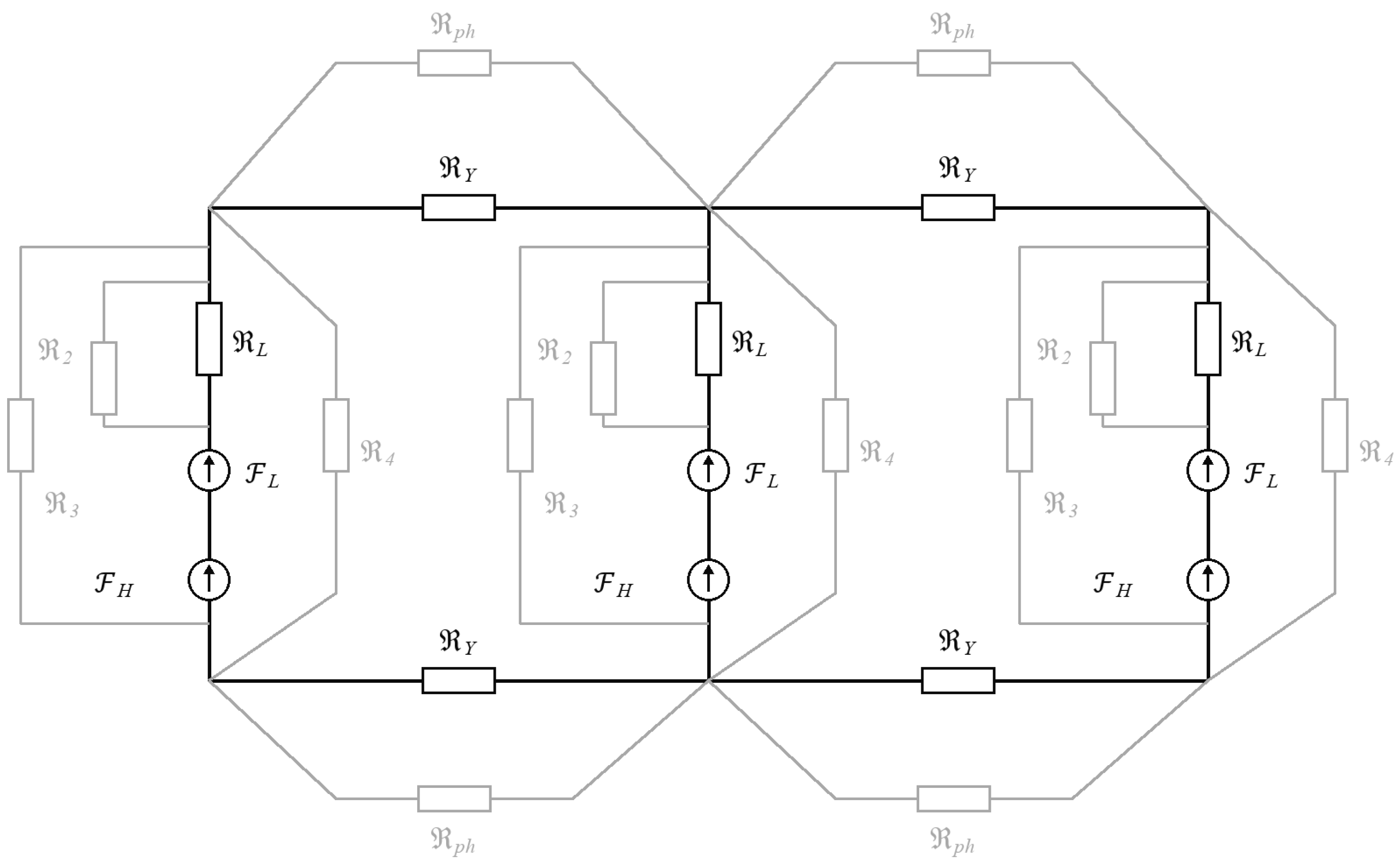
Figure 1 shows the reluctance paths that enforce this magnetic coupling.

2.5. Formation Mechanism of Magnetizing Inrush Current Under Combined Harmonic and DC-Bias Conditions

Let the effective limb flux include the residual state, prospective excursion, and the displacement associated with differential DC current. Equation (6) defines its positive- and negative-direction margins to the symmetric knee.
m k ± = ψ s a t , k ψ e , k
Here, mk+ and mk are the positive- and negative-direction saturation margins, ψsat,k is the symmetric knee-flux magnitude, and ψe,k is the effective flux after residual, harmonic, and DC-bias contributions are combined.
A positive-going harmonic increment compresses the positive margin and expands the negative margin; reversing its instantaneous direction exchanges those roles. Coupling strength is therefore governed by whether residual flux, DC-current displacement, and harmonic phase compress the same directional margin during the first major excursion, not by 1/h scaling alone. As a margin approaches zero, incremental permeability collapses, limb reluctance rises, and the shared-yoke constraint redistributes return flux and magnetizing current among phases. This sequence explains both non-additive peak growth and migration of the dominant phase. The margin-based interpretation is consistent with coupled electromagnetic transformer models and measurement-oriented inrush studies, which relate knee crossing, phase redistribution, and current severity to the nonlinear magnetic state [7,15,22].
The phase k residual-to-prospective flux mismatch is defined by Equation (7).
Δ ψ k = ψ r , k ψ p , k 0
The maximum normalized mismatch over all three phases is then defined by Equation (8).
D ψ = m a x k a b c Δ ψ k Ψ m
In Equations (7) and (8), Δψk is the phase-k residual-to-prospective mismatch, ψp,k(0) is the prospective flux at contact making, Dψ is the maximum normalized mismatch over the three phases, and Ψm is the selected flux normalization base.
The zero-residual-flux state provides a direct test of whether a single-phase description is sufficient. Setting all residual components to zero removes the magnetic-memory term, but the three prospective phase fluxes at contact making remain separated by their phase displacement and are further reshaped by harmonic sequence. Consequently, the phase that supplies the maximum in Dψ changes with command angle: phase-A matching can coincide with a larger phase-B or phase-C mismatch. Through the three-limb zero-sum constraint, the excursion of that dominant phase changes the return-path flux of the other two limbs. Angle sensitivity at zero residual flux is therefore evidence of three-phase magnetic coupling, rather than a contradiction in the mismatch definition, and it requires a phase-domain maximum instead of a phase-A scalar criterion.
Harmonic voltage modifies the prospective term, DC current modifies the operating point and the dynamic magnetizing slope, and the three-limb constraint redistributes the resulting flux. Inrush forms when their temporal combination crosses the saturation knee. If the harmonic excursion has the same instantaneous direction as the residual mismatch and DC displacement, the crossing occurs earlier, and the saturated interval widens. Opposite polarity can delay the crossing or move the dominant current to another limb. This is the physical basis of reinforcement and partial cancellation under combined conditions. Similar reinforcement and cancellation mechanisms have been reported in analytical and coupled-model studies of transformer inrush and harmonic distortion [7,15,16,22].
Flux matching minimizes the discontinuity at contact making, but the zero-sum constraint and a distorted source leave multiple combinations capable of producing a small three-phase maximum. Matching is therefore a sufficient favorable condition under the ideal constraints used to derive it, not a necessary condition for every low-current event. A practical controller must evaluate all phases and include the actual harmonic phase and expected DC displacement. The sufficiency of flux matching, together with its dependence on residual state and switching conditions, is also supported by controlled-switching and prefluxing studies [4,5,9,10].

3. Model Implementation and Operating Conditions

3.1. Three-Phase Three-Limb Transformer Model and Parameterization

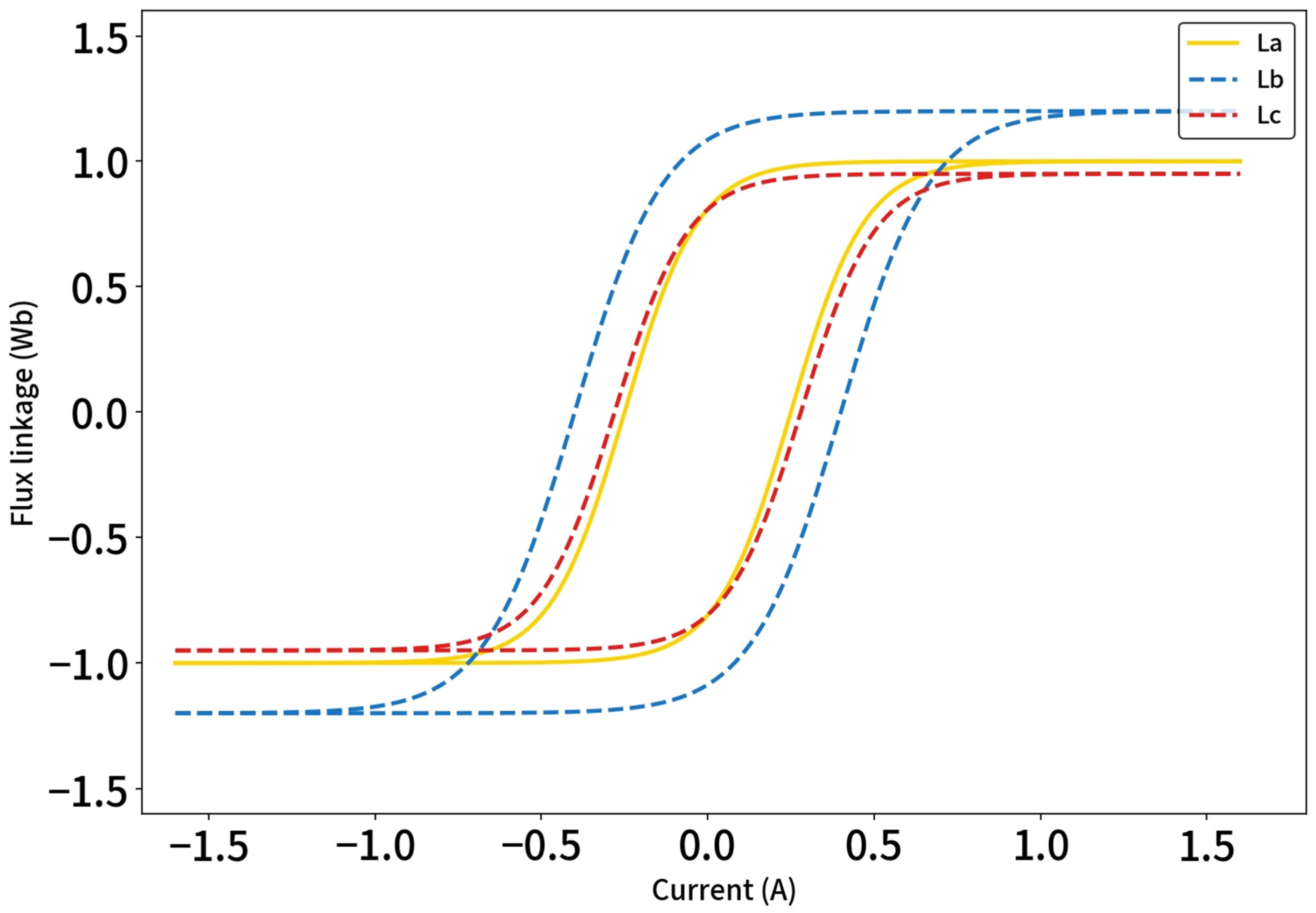
The model represents a 50 kVA, 10 kV/400 V, 50 Hz, Yyn0 transformer by coupled nonlinear limb branches, winding resistance and leakage inductance, core-loss branches, and a shared-yoke reluctance network. The measured major loops in Figure 2 inform residual-state polarity, phase-dependent knee ordering, and post-knee trends; nameplate, no-load, DC-resistance, and short-circuit tests constrain the electrical branches. This reduced parameterization follows the distinction between measured magnetic data and transient-model closure emphasized in [7,25].
Table 1 summarizes the nameplate and test parameters used to define the electrical and magnetic branches.
The rated high-voltage line current in Table 1 is the common normalization base for reported AC and injected DC currents. Saturation is represented phase by phase rather than by a single positive-sequence magnetizing inductance. Winding capacitance, detailed joint/air-gap geometry, tank return flux, and frequency-dependent losses are outside the present closing interval model; transformer-model reviews show that these elements must be restored for higher-frequency or topology-specific studies [21,24]; frequency-dependent thermal modeling that accounts for material anisotropy offers a complementary treatment when such material effects are retained [26]. Core temperature is held constant over each sweep.
Residual flux is initialized directly in the nonlinear branch states while satisfying the three-limb sum constraint to numerical tolerance. The breaker is represented by simultaneous three-pole contacts for the nominal sweep. Contact-making dispersion is treated as an implementation uncertainty because even a small mechanical timing error changes the realized electrical angle. This uncertainty becomes especially important near a narrow optimum and should be added to the command angle when transferring a selected setting to hardware [7,21].
During strong asymmetric saturation, leakage flux, yoke-joint reluctance, construction asymmetry, small air gaps, zero-sequence paths, and flux return through the tank or air can alter limb sharing. Here, their first-order influence is absorbed into leakage reactance and phase-dependent magnetic coefficients. The ideal three-limb projection cannot represent an externally closed common-mode flux path; such cases require a topology-based magnetic circuit or field model [22,24].

3.2. Modeling of Harmonic and DC-Bias Components

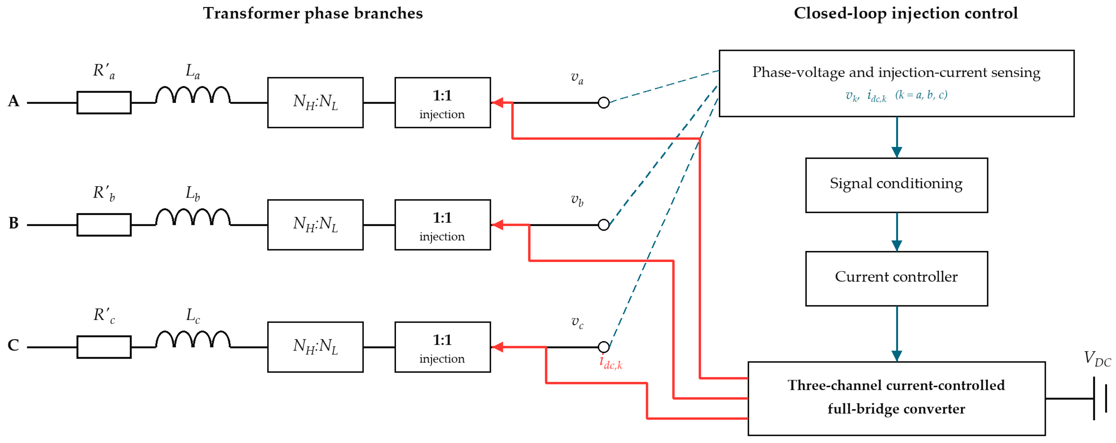
The AC source contains a balanced 50 Hz fundamental, and programmable negative-sequence harmonic voltages are superposed phase by phase. A separate three-channel closed-loop subsystem commands the phase-specific quasi-DC winding currents through the current-controlled full-bridge converter in Figure 3 using voltage and current feedback. Accordingly, harmonic voltage enters Equations (1)–(3), whereas the DC-current command is converted to the flux-linkage increment in Equation (4) and enters the effective-flux state in Equation (10). The same transformer and network parameters are retained in every condition.

3.3. Configuration of Individual and Combined Disturbance Conditions

Every operating condition includes balanced 50 Hz energization; labels identify only the additional perturbation. Breaker-command angles cover 0–330° at 30° intervals, with a 5° repeat used to test angular resolution. Each angle denotes the phase-A fundamental reference; phases B and C follow their electrical displacement and the specified harmonic sequence. Residual states include zero, scaled asymmetric, polarity-reversed, and approximately matched cases. Table 2 summarizes the disturbance matrix.
The second and fifth harmonics were selected because both belong to the negative-sequence families generated by the adopted phase progression, while their 1/h flux weighting separates a low-order even component from a common converter-related higher-order component. The 0.15 and 0.08 p.u. magnitudes are intentionally conservative programmable-source stress levels, not universal grid limits. Reference phases of 180° and 30° define a reproducible mixed case containing both margin compression and partial cancellation. Section 4.5 tests magnitude, phase, and order dependence; triplen components are excluded because the ideal zero-sum projection removes their common-mode voltage.
The DC commands are normalized to the 2.887 A high-voltage rated-current base. A single-phase command tests cross-limb transfer, and the 0.10/0.05/0 pattern introduces controlled differential asymmetry. An equal three-phase command is removed by Equation (4) and the zero-sum projection and would therefore reproduce the baseline exactly; it has been removed from Table 2. Representing common-mode neutral GIC requires an explicit neutral and external return-flux path, which is outside the present model.

3.4. Phase-Domain Numerical Implementation and Consistency Checks

A phase-domain nonlinear implementation resolves the time sequence of the coupled disturbance without prescribing a decay envelope. The winding-state derivative follows Equation (9), where the indexed coefficients denote the per-unit series resistance and leakage reactance of each phase. The denominator contains the instantaneous slope of the nonlinear magnetizing branch; consequently, current rise and transient decay emerge from the applied voltage, winding impedance, residual state, and knee crossing.
1 + x σ , k i m , k ψ e , k d ψ ~ k t d t = ω u k t r k i m , k , k a b c
Here, ψ ~ k is the projected flux state, im,k is the nonlinear magnetizing current, xσ,k and rk are the phase-k leakage reactance and series resistance in per unit, and ∂im,k/∂ψe,k is the instantaneous magnetizing-branch slope.
The integrated state and the DC flux-linkage increment defined in Equation (4) are both projected onto the three-limb zero-sum subspace by Equation (10). This operation prevents numerical drift or unequal phase conversion coefficients from creating a fictitious zero-sequence core flux.
ψ e , k = ψ ~ k 1 3 j a b c ψ ~ j + ψ d c , k 1 3 j a b c ψ d c , j
Here, ψdc,k is the DC flux-linkage increment defined in Equation (4), and the two summations over j remove the zero-sequence components of the integrated and DC-induced flux linkages before they are combined.
Figure 2 and Equation (11) serve different modeling roles. The remanent point and phase ordering of the measured major loops define the initial state and relative saturation thresholds. Equation (11) is a reduced single-valued backbone used to compute instantaneous magnetizing current and incremental slope. It does not reproduce loop width, minor-loop memory, or dynamic loss, so the measured loops are not claimed as a pointwise fit of Equation (11) [7,25].
The resulting single-valued state-equation closure is given by Equation (11). It retains phase-dependent knee position and post-knee steepness, while q > 1 controls the nonlinear rise beyond the knee.
i m , k = a k ψ e , k + b k s g n ψ e , k m a x | ψ e , k | ψ s a t , k , 0 q
Here, ak is the linear magnetizing slope, bk is the post-knee gain, q is the post-knee exponent, sgn(.) is the sign function, and max(.) limits the nonlinear excess to the portion beyond the knee flux ψsat,k.
Table 3 consolidates the fixed numerical, magnetic, network, residual-state, and disturbance settings used for the waveform and envelope results in Section 4; only the explicitly swept variable is changed in each sensitivity test.
The MATLAB R2023b fixed-step RK4 calculation exports the complete flux and current histories used for the waveform and envelope results reported in Section 4. Reducing the step from 20 μs to 10 μs changes the largest peak by at most 4.12 × 10⁻⁶ and K4 by at most 9.18 × 10⁻⁶; the maximum three-phase flux-sum residual is 2.22 × 10⁻¹⁶ p.u. These checks demonstrate numerical convergence and constraint enforcement; they are not used as evidence of physical model validation.

3.5. Quantification of Coupling Effects and Inrush-Current Evaluation Indices

Maximum and minimum phase-current envelopes are extracted over the common 0.30 s window. Decay time is the end of the last 20 ms cycle whose three-phase absolute-current maximum exceeds 20% of the case peak. Equation (12) then defines a normalized fourth-order three-phase current norm that retains phase participation and emphasizes large excursions.
K 4 = 1 3 T w k a b c 0 T w i k I N 4 d t 1 4
Here, K4 is the dimensionless fourth-order three-phase current norm, Tw is the common observation-window length, ik(t) is the phase current, and IN is the rated-current base listed in Table 1.
The fourth root in Equation (12) keeps K4 linear in current. K4 is a fourth-order current norm, not a direct force, energy, or force-rms measure. The choice p = 4 is motivated by the approximate current-squared dependence of winding force [27], while three-dimensional frequency-response-analysis signatures provide complementary evidence of winding mechanical condition [28]: the fourth-power integrand is the square of a normalized current-squared force proxy, whereas time integration prevents one sample from defining the index. Its ranking is therefore checked against peak and rms current in Section 4.5. Non-additive interaction is quantified by Equation (13).
C I = I p k , H + D C I p k , H I p k , D C + I p k , 0 I N
Here, CI is the peak interaction contrast; Ipk,H+DC, Ipk,H, Ipk,DC, and Ipk,0 are the four-case three-phase peak currents with both, harmonic-only, DC-only, and no additional disturbance, respectively.
Positive CI denotes reinforcement beyond additive individual increments, whereas negative CI denotes partial cancellation. Because CI is a four-case contrast, all currents use the same residual state, command angle, network impedance, and observation window. Phase-current distortion is defined by Equation (14).
T H D k = n = 2 n m a x I n , k 2 I 1 , k × 100 %
Here, THDk is the total harmonic distortion of phase k, In,k is its nth-harmonic rms component, I1,k is its fundamental rms component, and nmax is the highest retained order. The corresponding sequence ratio is defined by Equation (15).
ρ I = I 2 I 1 × 100 %
Here, ρI is the negative-sequence current ratio, while I2 and I1 are the negative- and positive-sequence rms current magnitudes, respectively.
The Fourier window is 0.01–0.29 s, which begins after the first half cycle and contains 14 complete 50 Hz cycles. Harmonics through order 10 are retained. Because the waveform is decaying rather than stationary, the reported THD values characterize this defined transient segment and should not be interpreted as steady-state power-quality indices. The negative-sequence ratio is calculated from the fundamental phasors over the same window.

4. Simulation Results and Analysis

4.1. Inrush Characteristics Under Individual Harmonic and DC-Bias Conditions

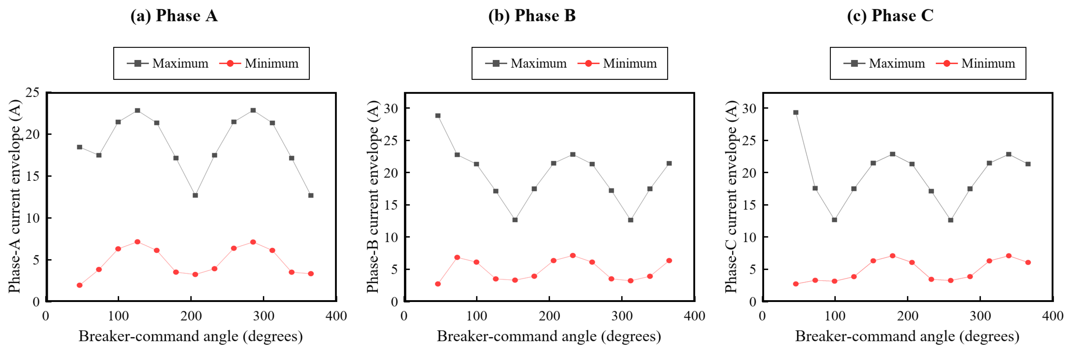
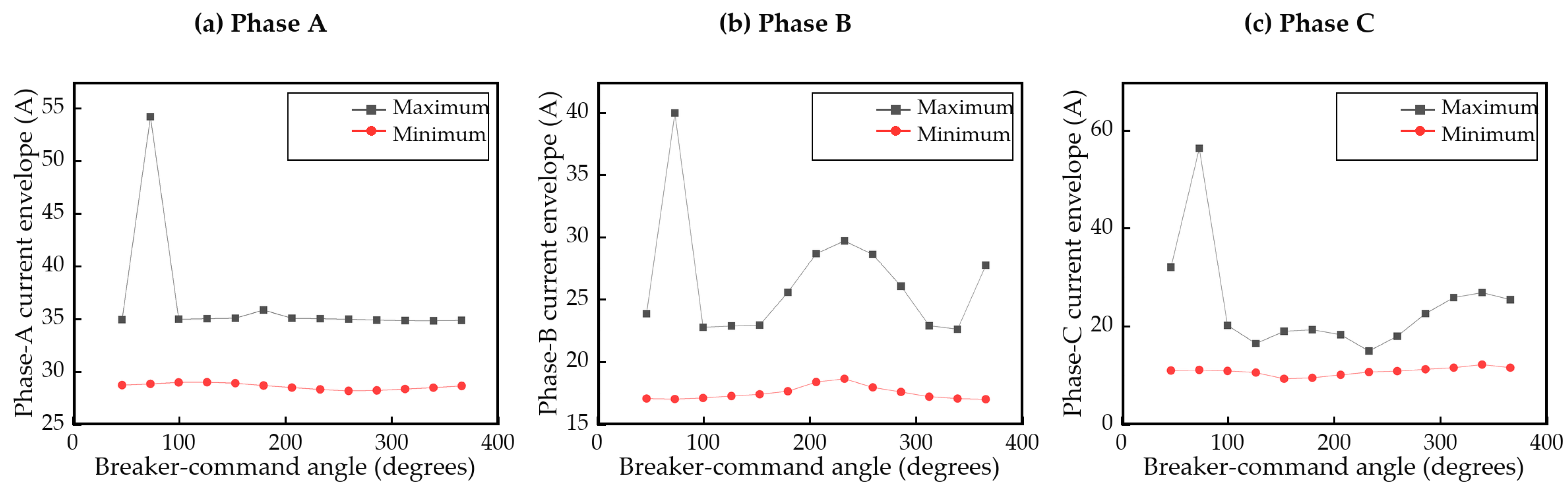
Figure 4 presents model-derived cycle-current envelopes over the breaker-command-angle sweep. The maximum and minimum curves are the largest and smallest cycle maxima for each phase at each command angle, rather than signed extrema of one waveform. The phase containing the upper bound migrates with the three prospective-flux trajectories.
At 60°, the Figure 4 upper envelopes are approximately 21.4, 21.2, and 12.8 A for phases A, B, and C. The corresponding time-domain peaks are 21.30, 21.15, and 12.88 A, so the angle-envelope and time-domain outputs agree in phase ordering and amplitude scale. The positive lower curves are cycle-envelope minima, not instantaneous current minima.
Figure 5 applies the 0.10/0.05/0 p.u. differential DC command. At 60°, its phase-A, phase-B, and phase-C upper envelopes are approximately 35.0, 22.8, and 20.0 A; the corresponding time-domain peaks are 35.15, 22.95, and 19.89 A. The matched values confirm internal consistency between the angle sweep and the displayed waveform calculation.
Across the angle sweep, the DC-biased upper envelope reaches approximately 54 A in phase A, 40 A in phase B, and 57 A in phase C at different command angles. These sweep-wide maxima need not occur at the displayed 60° condition; direct comparison is made only between values at the same command angle.

4.2. Inrush Magnitude and Decay Characteristics Under Combined Harmonic and DC-Bias Conditions

Combined harmonic-voltage and DC-current excitation must be interpreted through a causal sequence. Harmonic order, sequence, and phase first reshape the prospective limb-flux trajectories. The DC current translates the magnetic operating point and makes the positive and negative margins unequal. When a trajectory exhausts the compressed margin, incremental permeability collapses; the corresponding increase in limb reluctance changes shared-yoke magnetomotive-force balance and redistributes current demand among the three phases. The resulting peak and current floor therefore cannot be obtained by adding the separate current traces.
For a fixed residual state, reinforcement occurs when the harmonic prospective-flux increment points toward the knee selected by the DC-current displacement during the first major excursion. If the increment points in the opposite direction, the first crossing may be delayed even though later half cycles remain biased. The peak contrast CI distinguishes this non-additivity, while decay time and K4 reveal whether a lower first peak is accompanied by repeated saturation. A reduction in K4 is therefore interpreted as lower sustained high-current severity over the common window, not merely as a shorter transient.
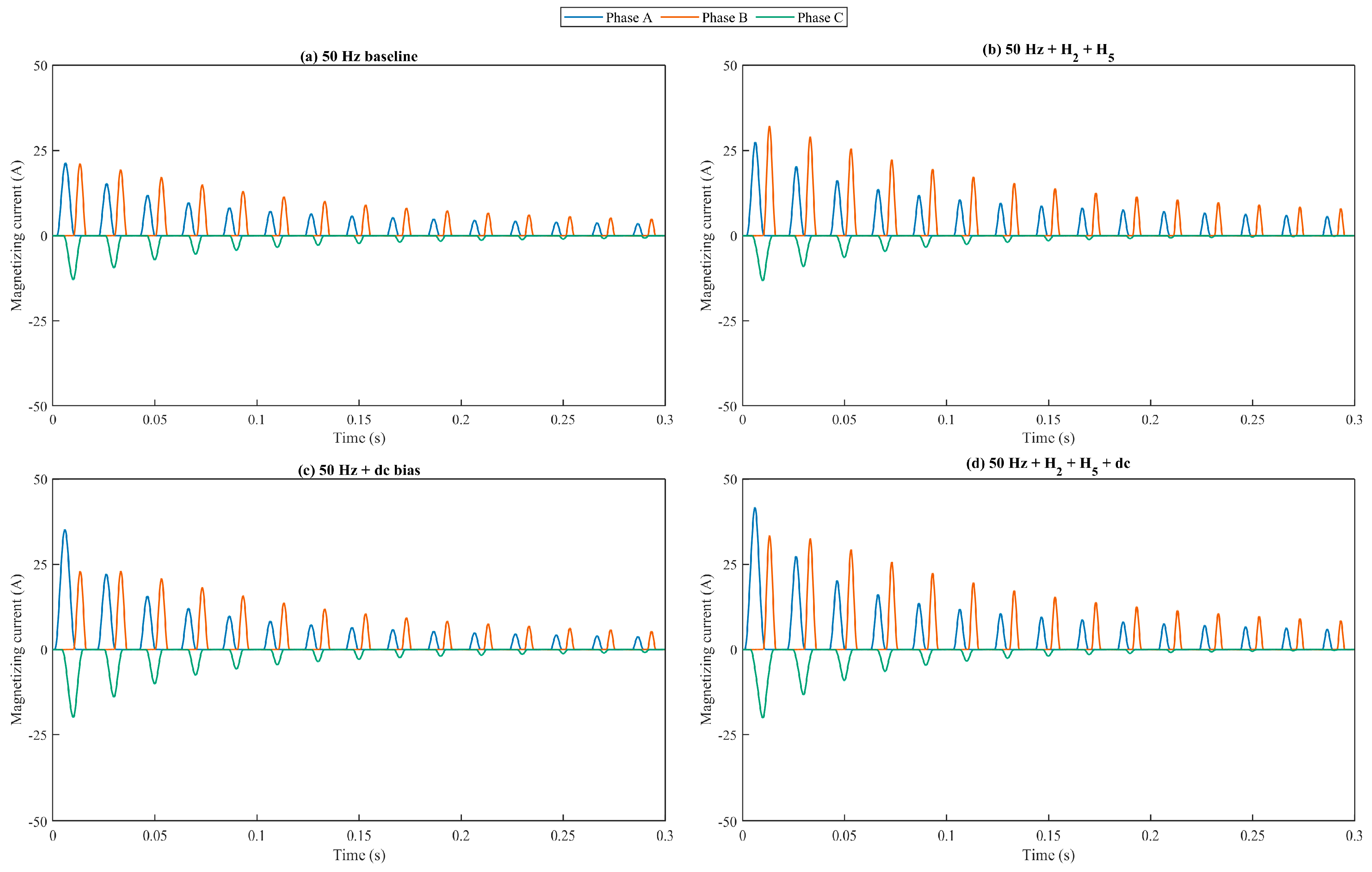
Figure 6 compares four complete energization cases at the 60° command angle using the common initial state and numerical settings in Table 3. Every case contains the 50 Hz fundamental, and each panel displays phases A, B, and C together. Harmonic voltage advances and reshapes the phase-A and phase-B pulses, DC bias increases the phase-A saturation depth, and their combination produces the largest phase-A excursion. Phase C remains smaller in the harmonic cases but increases under DC bias, demonstrating phase-selective knee crossing rather than uniform scaling.
The peak statistic is the largest absolute instantaneous phase current among phases A, B, and C over the 0.30 s window. On the common high-voltage rated-current base of 2.887 A, the baseline, harmonic-voltage, DC-biased, and combined peaks are 7.38, 11.15, 12.18, and 14.43 p.u., equivalent to 21.30, 32.19, 35.15, and 41.67 A, respectively. The corresponding K4 values are 2.28, 3.17, 3.28, and 4.04 p.u. Relative to baseline, the combined condition raises the peak by 95.7% and K4 by 77.0%. The peak interaction contrast CI is −1.518 p.u., indicating partial cancellation of the individual peak increments; the K4 four-case contrast is −0.1409 p.u., indicating partial cancellation in the integrated current norm.
Table 4 supplies the decay, distortion, and unbalance values defined in Section 3.5. The harmonic case has the highest negative-sequence ratio (36.2%), while the DC-only case decays below the threshold by 220 ms. The other three cases remain above the threshold at the end of the common window and are reported as right-censored rather than extrapolated.
The negative CI value in the four-case comparison describes non-additivity of the complete model output. It does not, by itself, identify a new physical coupling coefficient. The non-additivity originates in the single-valued magnetic nonlinearity; three-limb sharing changes its phase distribution through the zero-sum projection, and network impedance limits the current after incremental permeability collapses. Isolating these contributions would require controlled model ablations, whereas the present CI is used only as a matched four-case contrast.
The appropriate closing command minimizes a three-phase objective, not necessarily the phase-A peak. The controlled-switching theory in [4,5], the three-phase studies in [10,20], and inverter-limited energization results in [19] all show that the realized benefit depends on residual state, breaker timing, and source dynamics. Under a distorted source, the candidate interval must be computed from the full harmonic prospective-flux vector.
Decay and peak magnitude are network-dependent. In the source-impedance sweep in Table 5, increasing both series resistance and leakage reactance by 20% lowers the combined peak from 41.67 to 38.14 A, whereas reducing them by 20% raises it to 46.25 A. This direction agrees with the parameter sensitivity and measured/model comparisons reported by Chiesa et al. [7] and Nițu et al. [29].
The comparison with published measurements is therefore restricted to response direction and parameter ranking. The absolute values in this paper apply to the modeled 50 kVA transformer and require recalibration and transient switching tests before they are transferred to another design [7,29].

4.3. Harmonic-Order Contribution and Three-Phase Current Unbalance

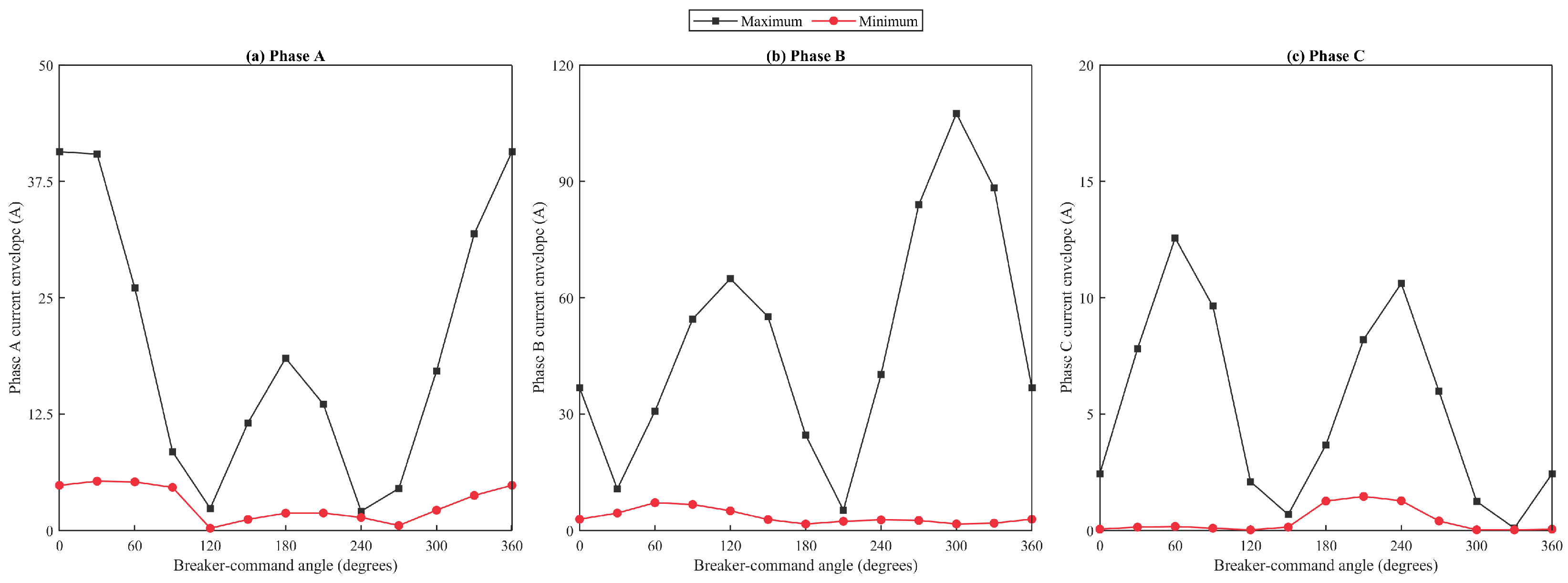
Figure 7 shows the current envelopes for a 0.15 p.u., 180° negative-sequence second harmonic calculated with the same parameter set as Figure 6. Its 1/h weighting in Equation (3) gives substantial prospective-flux leverage, but the observed phase selectivity also depends on negative-sequence rotation, residual polarity, and the directional margins in Equation (6). Across the angle sweep, the phase-A, phase-B, and phase-C maximum envelopes reach 40.7, 107.5, and 12.6 A, respectively, at different command angles; the largest lower-envelope value is 7.2 A. At 60°, the second-harmonic phase peaks are 26.05, 30.74, and 12.57 A.
The reverse phase progression of the second harmonic shifts its relative phase against each fundamental limb voltage. As the command angle advances, the phase with the smallest flux margin changes; the largest current consequently migrates from one limb to another. This mechanism also increases negative-sequence current and prevents the phase THD values from being interpreted as copies of a single waveform.
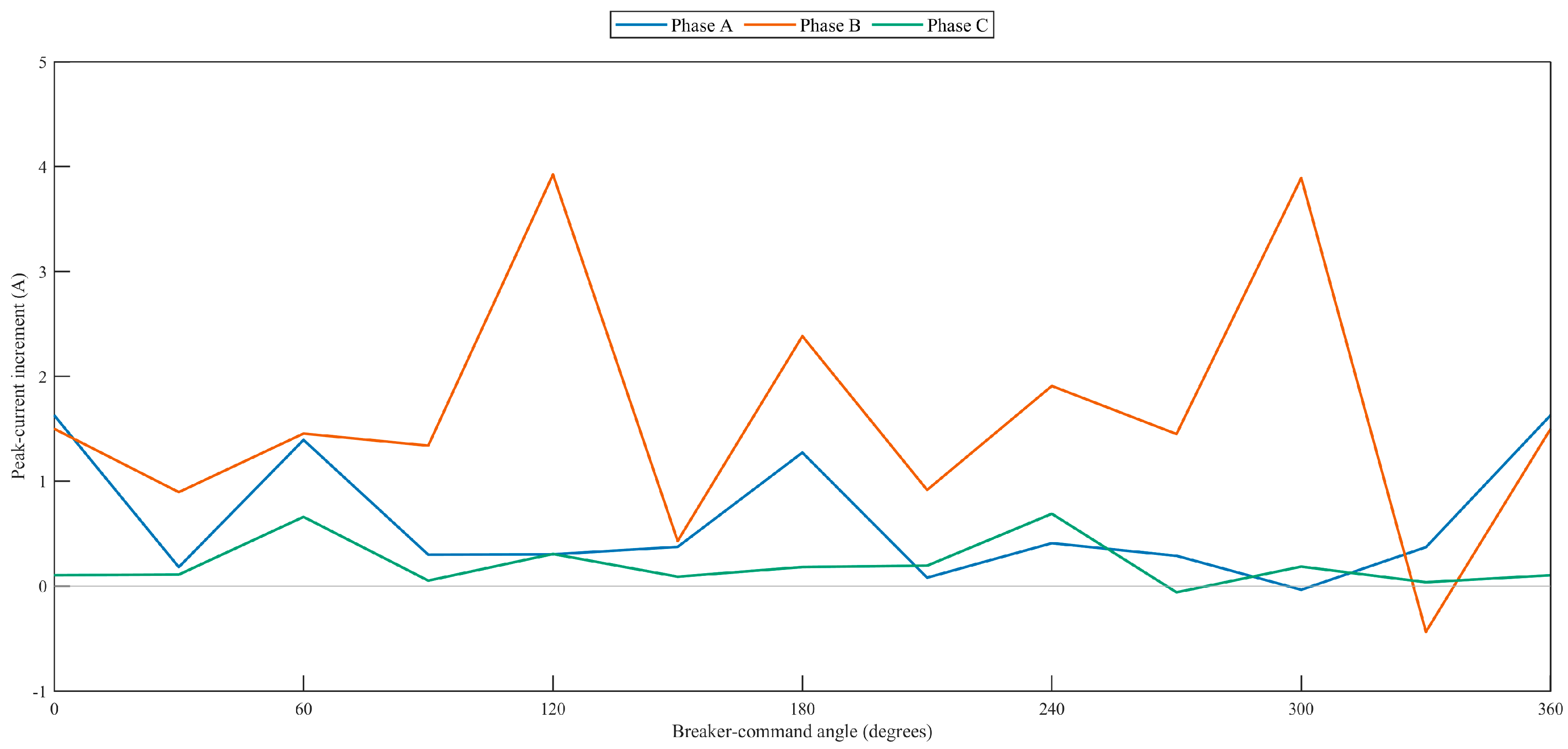
Because the full mixed-harmonic envelope closely follows Figure 7, Figure 8 isolates the phase-peak increment obtained after adding the 0.08 p.u., 30° negative-sequence fifth harmonic to the second-harmonic case. The increment ranges from −0.44 to +3.92 A over the angle sweep. At 60°, the mixed-harmonic peaks are 27.44, 32.19, and 13.23 A, identical to the harmonic-only panel of Figure 6 within numerical precision. The sign reversals show that the fifth harmonic can either compress or expand the active directional margin according to phase and command angle.
The small direct fifth-harmonic flux contribution can still alter the current spectrum because a slight shift of the knee-crossing instant changes saturation depth and pulse width. Voltage-spectrum magnitude therefore cannot be mapped directly to current THD. THD and negative-sequence ratio should be reported with the peak increment and evaluated over the same transient window.

4.4. Effects of Energization Angle and Residual-Flux State on Coupling Strength

The operating sets establish three distinct angular signatures. The sinusoidal baseline is quasi-periodic and moderate; asymmetric DC-current injection raises the current floor and introduces phase-specific maxima; harmonic voltage produces sharper peak migration. Their differences follow the coupling mechanism in Section 2: residual flux selects the initial side of the loop, the command angle and harmonic sequence set the prospective vector, DC current makes the directional margins unequal, and the shared yokes redistribute the response after incremental permeability collapses.
Residual polarity reverses the relation between DC displacement and the first harmonic-modulated excursion. A command angle that is favorable for a positive A-phase residual state can therefore be unfavorable after that state is reversed. More importantly, the zero-residual-flux sweep isolates coupling from magnetic memory: Dψ remains angle-dependent because its maximizing phase migrates among A, B, and C, and the shared yokes transfer the dominant-limb reluctance change into the other two current responses. The zero-residual case thus demonstrates why three-pole severity cannot be inferred from phase A alone and why the coupled phase-domain objective is necessary.
An approximately matched residual state reduces the fundamental mismatch, but it is only a sufficient favorable condition under the idealized constraints; it is not necessary for every low-current case. Harmonic phase and DC polarity can still move the operating point toward or away from the knee. Conversely, a nonmatched state may produce a moderate maximum if the first distorted prospective excursion opposes the residual flux and the other limbs remain below the knee.
A practical controller should minimize a robust coupled objective containing Dψ, predicted K4, the three-phase current maximum, and contact-making dispersion. If the acceptable interval is narrower than breaker scatter, prefluxing, controlled switching, or soft energization can enlarge the operating margin [4,8,19,20]. Temporary current limiting provides an additional electrical bound when magnetic-state control is unavailable.

4.5. Sensitivity, Indicator Comparison, and Model Scope

Table 5 varies one factor at a time without re-fitting the calibrated coefficients. Residual-flux and magnetic-parameter tests use the combined 60° case; harmonic tests use the harmonic-only 60° case; the angular test repeats the combined sweep. The ranges are intended to test conclusion stability, not to define universal operating limits.
The four 60° cases have the same severity ranking under peak current, K4, and three-phase rms current: baseline < harmonic < DC bias < combined. The rms values are 1.11, 1.50, 1.53, and 1.90 p.u., respectively. This agreement supports K4 as a supplementary high-current-duration indicator for the present dataset, but not as a standardized force measure. The phase and order sweeps also show that 1/h weighting alone does not rank current severity after sequence, phase, knee crossing, and shared-yoke redistribution are included.
The model has no transient switching measurements for the studied unit. It also uses a single-valued magnetic backbone and an idealized zero-sum core constraint. Consequently, numerical convergence, the Figure 4, Figure 5 and Figure 6 consistency check, and literature trend agreement do not substitute for laboratory validation. The reported results should be read as mechanism-level and relative-ranking evidence for the selected harmonic, differential-bias, residual-state, and network conditions.

5. Conclusions

The main methodological contribution is a phase-domain separation-and-recombination framework: harmonic voltage enters prospective flux through time integration, controlled differential DC current enters through magnetomotive-force displacement, and the two are recombined only inside the nonlinear three-limb state equation. This resolves the source-type ambiguity and makes the assumptions behind the interaction contrast explicit.
For the 60° case, the baseline, harmonic, DC-biased, and combined peaks are 21.30, 32.19, 35.15, and 41.67 A; the corresponding K4 values are 2.28, 3.17, 3.28, and 4.04 p.u. The harmonic case gives the largest fundamental negative-sequence ratio, 36.2%, whereas the DC-only case reaches the 20% decay threshold at 220 ms. The remaining cases are still above the threshold at 300 ms and are reported as right-censored.
The sensitivity study shows that a ±20% source-impedance change shifts the combined peak from 46.25 to 38.14 A, second-harmonic phase changes the harmonic-only peak from 17.99 to 32.19 A, and a 5° angle sweep changes the maximum from 114.14 A at 300° to 114.19 A at 295°. The identical peak, rms, and K4 ranking supports the use of K4 as a supplementary index for this dataset.
The conclusions are limited by the reduced single-valued magnetic backbone, idealized three-limb zero-sum constraint, omission of explicit tank/air return flux and common-mode neutral paths, and absence of transient switching measurements for the studied unit. Accordingly, the results establish mechanism and relative ranking only for the modeled distorted-source and differential-bias conditions.
Future work will identify a dynamic hysteresis model from digitized major and minor loops, add topology-based leakage and zero-sequence paths, and compare representative harmonic-phase and DC-bias cases with synchronized three-phase switching records. Breaker-time dispersion and transformer-design variation should then be included in a probabilistic robust-closing assessment.

Author Contributions

Conceptualization, J.H. and W.X.; Methodology, J.H., C.L., S.G., S.P., F.R. and X.G.; Software, C.L., S.P. and J.Y.; Validation, S.P., J.Y. and X.G.; Formal analysis, C.L., S.H. and X.Z.; Investigation, J.H., S.G., S.H. and S.P.; Resources, J.H., S.G., S.H., W.X., F.R., X.G. and X.Z.; Data curation, S.G., S.H., F.X. and J.Y.; Writing—original draft, J.H.; Visualization, F.X. and X.Z.; Supervision, F.X. and X.Z.; Project administration, X.Z. All authors have read and agreed to the published version of the manuscript.

Funding

This research was funded by Science and Technology Project Funding of State Grid Jiangsu Electric Power Company grant number J2025155.

Data Availability Statement

The data presented in this study are available on request from the corresponding author. The data are not publicly available due to privacy restrictions.

Conflicts of Interest

Authors Junchi He, Shaofan Gu, Shoujiang He, Shouhua Pan, Wenjing Xu, Fei Ren and Fan Xu were employed by the State Grid Guanyun Power Supply Company. Author Chenlei Li was employed by the Jiangsu Electric Power Company. The remaining authors declare that the research was conducted in the absence of any commercial or financial relationships that could be construed as a potential conflict of interest. The authors declare that this study received funding from Science and Technology Project Funding of State Grid Jiangsu Electric Power Company. The funder was not involved in the study design, collection, analysis, interpretation of data, the writing of this article or the decision to submit it for publication.

References

  1. Specht, T.R. Transformer magnetizing inrush currents. Trans. AIEE 1951, 70, 323–327. [Google Scholar] [CrossRef] [Scilit]
  2. Holcomb, J.E. Distribution transformer magnetizing inrush current. Trans. AIEE Part III Power Appar. Syst. 1961, 80, 697–702. [Google Scholar] [CrossRef] [Scilit]
  3. Zhao, X.; Tong, H.; Wu, H.; Abu-Siada, A.; Li, K.; Yao, C. A comprehensive review of reliability analysis for pulsed power supplies. Energies 2026, 19, 518. [Google Scholar] [CrossRef] [Scilit]
  4. Brunke, J.H.; Froehlich, K.J. Elimination of transformer inrush currents by controlled switching—Part I: Theoretical considerations. IEEE Trans. Power Deliv. 2001, 16, 276–280. [Google Scholar] [CrossRef] [Scilit]
  5. Brunke, J.H.; Froehlich, K.J. Elimination of transformer inrush currents by controlled switching—Part II: Application and performance considerations. IEEE Trans. Power Deliv. 2001, 16, 281–285. [Google Scholar] [CrossRef] [Scilit]
  6. Zhao, X.; Wu, H.; Yang, D.; Wei, J.; Li, Z.; Guo, Z.; Zhang, S. Residual magnetism elimination method for large power transformers based on energy storage oscillation. IEEE Trans. Power Deliv. 2025, 40, 2759–2768. [Google Scholar] [CrossRef] [Scilit]
  7. Chiesa, N.; Mork, B.A.; Høidalen, H.K. Transformer model for inrush current calculations: Simulations, measurements and sensitivity analysis. IEEE Trans. Power Deliv. 2010, 25, 2599–2608. [Google Scholar] [CrossRef] [Scilit]
  8. Chiesa, N.; Høidalen, H.K. Novel approach for reducing transformer inrush currents: Laboratory measurements, analytical interpretation and simulation studies. IEEE Trans. Power Deliv. 2010, 25, 2609–2616. [Google Scholar] [CrossRef] [Scilit]
  9. Cui, Y.; Abdulsalam, S.G.; Chen, S.; Xu, W. A sequential phase energization technique for transformer inrush current reduction-Part I: Simulation and experimental results. IEEE Trans. Power Deliv. 2005, 20, 943–949. [Google Scholar] [CrossRef] [Scilit]
  10. Mitra, J.; Xu, X.; Benidris, M. Reduction of three-phase transformer inrush currents using controlled switching. IEEE Trans. Ind. Appl. 2020, 56, 890–897. [Google Scholar] [CrossRef]
  11. Pan, Y.; Yin, X.; Zhang, Z.; Liu, B.; Wang, M.; Yin, X. Three-phase transformer inrush current reduction strategy based on prefluxing and controlled switching. IEEE Access 2021, 9, 38961–38978. [Google Scholar] [CrossRef] [Scilit]
  12. Pachore, P.; Gupta, Y.; Anand, S.; Sarkar, S.; Mathur, A.; Singh, P.K. Flux error function based controlled switching method for minimizing inrush current in 3-phase transformer. IEEE Trans. Power Deliv. 2021, 36, 870–879. [Google Scholar] [CrossRef] [Scilit]
  13. Hamilton, R. Analysis of transformer inrush current and comparison of harmonic restraint methods in transformer protection. IEEE Trans. Ind. Appl. 2013, 49, 1890–1899. [Google Scholar] [CrossRef] [Scilit]
  14. Raichura, M.B.; Patel, N.C. Review of methodologies used for detection of magnetising inrush and fault conditions in power transformer. IET Energy Syst. Integr. 2021, 3, 230–246. [Google Scholar] [CrossRef] [Scilit]
  15. Cheng, C.L.; Lin, C.E.; Huang, C.L.; Yeh, J.C. A simple model for transformer inrush current calculation and harmonic analysis. Electr. Power Syst. Res. 1992, 24, 153–163. [Google Scholar] [CrossRef] [Scilit]
  16. Boteler, D.H.; Shier, R.M.; Watanabe, T.; Horita, R.E. Effects of geomagnetically induced currents in the BC Hydro 500 kV system. IEEE Trans. Power Deliv. 1989, 4, 818–823. [Google Scholar] [CrossRef] [Scilit]
  17. Rezaei-Zare, A. Behavior of single-phase transformers under geomagnetically induced current conditions. IEEE Trans. Power Deliv. 2014, 29, 916–925. [Google Scholar] [CrossRef] [Scilit]
  18. Price, P.R. Geomagnetically induced current effects on transformers. IEEE Trans. Power Deliv. 2002, 17, 1002–1008. [Google Scholar] [CrossRef] [Scilit]
  19. Alassi, A.; Ahmed, K.H.; Egea-Alvarez, A.; Foote, C. Transformer inrush current mitigation techniques for grid-forming inverters dominated grids. IEEE Trans. Power Deliv. 2023, 38, 1610–1620. [Google Scholar] [CrossRef] [Scilit]
  20. Łukaniszyn, M.; Baron, B.; Kolańska-Pluska, J.; Majka, Ł. Inrush current reduction strategy for a three-phase Dy transformer based on pre-magnetization of the columns and controlled switching. Energies 2023, 16, 5238. [Google Scholar] [CrossRef] [Scilit]
  21. Martinez, J.A.; Walling, R.; Mork, B.A.; Martin-Arnedo, J.; Durbak, D. Parameter determination for modeling system transients-Part III: Transformers. IEEE Trans. Power Deliv. 2005, 20, 2051–2062. [Google Scholar] [CrossRef] [Scilit]
  22. Yacamini, R.; Bronzeado, H. Transformer inrush calculations using a coupled electromagnetic model. IEE Proc. Sci. Meas. Technol. 1994, 141, 491–498. [Google Scholar] [CrossRef] [Scilit]
  23. Zhao, X.; Wu, H.; Tong, H.; Zhang, S.; Ma, J.; Li, K.; Yao, C. High-efficiency stacked Blumlein pulse generator using a multi-Boost topology with magnetic coupling suppression. IEEE Trans. Power Electron. 2026, 41, 16803–16815. [Google Scholar] [CrossRef] [Scilit]
  24. Martinez, J.A.; Mork, B.A. Transformer modeling for low- and mid-frequency transients-A review. IEEE Trans. Power Deliv. 2005, 20, 1625–1632. [Google Scholar] [CrossRef] [Scilit]
  25. Yonezawa, R.; Noda, T.; Suzuki, N.; Nagashima, H.; Nomiyama, F.; Yamaguchi, N.; Honma, H.; Kitamura, S. Development of a transformer magnetizing circuit model for inrush current and residual flux calculations. IEEJ Trans. Power Energy 2014, 134, 749–758. [Google Scholar] [CrossRef] [Scilit]
  26. Zhao, X.; Wei, J.; Lv, Y.; Yue, S.; Ren, F.; Zhang, S.; Abu-Siada, A.; Li, K.; Li, Y. Frequency-dependent thermal modeling of high-power, high-frequency transformers considering material anisotropy. Electr. Power Syst. Res. 2026, 258, 113054. [Google Scholar] [CrossRef] [Scilit]
  27. Faiz, J.; Ebrahimi, B.M.; Noori, T. Three- and two-dimensional finite-element computation of inrush current and short-circuit electromagnetic forces on windings of a three-phase core-type power transformer. IEEE Trans. Magn. 2008, 44, 590–597. [Google Scholar] [CrossRef] [Scilit]
  28. Zhao, X.; Wu, G.; Yang, D.; Xu, G.; Xing, Y.; Yao, C.; Abu-Siada, A. Enhanced detection of power transformer winding faults through 3D FRA signatures and image processing techniques. Electr. Power Syst. Res. 2025, 242, 111433. [Google Scholar] [CrossRef] [Scilit]
  29. Nițu, M.-C.; Nicolae, I.-D.; Dina, L.-A.; Mircea, P.-M. Power transformer inrush current analysis: Simulation, measurement and effects. Appl. Sci. 2024, 14, 10926. [Google Scholar] [CrossRef] [Scilit]
Figure 1. Reluctance network of the three-phase three-limb core. Script symbols ℜ and denote reluctance and magnetomotive force, respectively.
Energies 19 04455 g001
Figure 2. Measured phase major hysteresis loops used to identify remanent state, phase-dependent knee ordering, and post-knee trends.
Energies 19 04455 g002
Figure 3. Three-phase transformer energization model with three independent, closed-loop, current-controlled DC-injection channels.
Energies 19 04455 g003
Figure 4. Phase-current envelopes under sinusoidal excitation and asymmetric residual flux.
Energies 19 04455 g004
Figure 5. Phase-current envelopes under a 0.10/0.05/0 p.u. asymmetric DC-current command and asymmetric residual flux.
Energies 19 04455 g005
Figure 6. Three-phase magnetizing-current waveforms at a 60° breaker-command angle: (a) 50 Hz baseline; (b) 50 Hz with second- and fifth-harmonic voltage; (c) 50 Hz with controlled DC-current bias; and (d) 50 Hz with both perturbations. Each panel contains phases A, B, and C. Currents are referred to the high-voltage side using the 2.887 A rated-current base.
Energies 19 04455 g006
Figure 7. Phase-current envelopes with a 0.15 p.u., 180° negative-sequence second harmonic and asymmetric residual flux.
Energies 19 04455 g007
Figure 8. Increment in the three-phase peak-current envelopes produced by adding a 0.08 p.u., 30° negative-sequence fifth harmonic to the second-harmonic condition.
Energies 19 04455 g008
Table 1. Transformer parameters used in the transient model.
ParameterValueParameterValue
Rated frequency50 HzRated capacity50 kVA
Voltage ratio and vector group10 kV/400 V, Yyn0No-load current≤1.3%
Short-circuit impedance3.95%No-load loss0.100 kW
High-/low-voltage DC resistance60 Ω/32 mΩRated high-voltage current2.887 A
Table 2. Disturbance conditions.
ConditionVoltage ExcitationDC-Current CommandPurpose
Baseline50 Hz fundamentalNoneReference
Second harmonic50 Hz + H2: 0.15 p.u.; 180°; negative seq.NoneLow-order effect
Fifth harmonic50 Hz + H5: 0.08 p.u.; 30°; negative seq.NoneHigh-order effect
Combined harmonics50 Hz + H2 + H5NoneJoint harmonic effect
Single-phase DC50 Hz fundamentalA: 0.05, 0.10, or 0.15 p.u. (0.144, 0.289, or 0.433 A)Bias-magnitude sweep
Asymmetric DC50 Hz fundamentalA/B/C: 0.10/0.05/0 p.u. (0.289/0.144/0 A)Asymmetric DC shift
Combined disturbance50 Hz + H2 + H5A/B/C: 0.10/0.05/0 p.u. (0.289/0.144/0 A)Coupled response
Table 3. Settings used for the phase-domain coupled-condition calculation.
SettingValueSettingValue
Time step20 μsObservation window0.30 s
Residual flux(0.265, −0.201, −0.064) p.u.Series resistance0.0212 p.u.
Second harmonic0.15 p.u.; 180°; negative seq.Fifth harmonic0.08 p.u.; 30°; negative seq.
DC-current command(0.10, 0.05, 0) p.u.Angle sweep0–330°; 30° step
Knee flux (A/B/C)(0.900, 0.900, 1.071) p.u.Displayed angle60°
Linear slope0.012Post-knee gain (A/B/C)(20.14, 121.12, 7.61)
Post-knee exponent2.2DC flux-linkage gain (A/B/C)(6.67, 18.00, 6.43) p.u./p.u.
Leakage reactance0.0395 p.u.Flux-sum residual2.22 × 10−16 p.u.
All four waveform conditions at 60° use the same residual state, winding parameters, nonlinear characteristic, time step, and observation window.
Table 4. Quantitative current metrics at the 60° breaker-command angle.
ConditionPeak (A)Decay (ms)K4 (p.u.)THD A (%)THD B (%)THD C (%)I2/I1 (%)
Baseline21.30≥3002.28100.6120.796.026.6
Harmonic voltage32.19≥3003.17107.8126.489.336.2
DC bias35.152203.2892.7116.186.922.7
Combined41.67≥3004.04100.6122.480.032.0
Decay values marked ≥300 ms are right-censored by the 0.30 s observation window. THD uses orders 2–10 over 0.01–0.29 s; I2/I1 is the fundamental negative-to-positive sequence ratio over the same interval.
Table 5. One-factor sensitivity and angular-resolution results.
FactorLevelsPeak-Current ResponseK4 Response
Residual-flux scale0, 0.5, 1.0, 1.540.74–48.67 A4.03–4.35 p.u.
Source-impedance scale0.8, 1.0, 1.246.25 to 38.14 A4.47 to 3.72 p.u.
Second-harmonic phase0°, 90°, 180°, 270°17.99–32.19 A1.76–3.17 p.u.
Second-harmonic magnitude0.05–0.20 p.u.24.23–34.16 A2.52–3.34 p.u.
Harmonic order2, 4, 5, 7 at 0.08 p.u.18.37–22.77 A1.98–2.38 p.u.
Knee-flux scale0.95, 1.0543.54 to 39.79 A4.34 to 3.75 p.u.
Post-knee-gain scale0.9, 1.139.42 to 43.78 A3.81 to 4.25 p.u.
Command-angle step30° versus 5°Max: 114.14 A at 300° versus 114.19 A at 295°Max: 9.43 p.u. at 300° versus 9.48 p.u. at 295°
Peak-current ranges are computed from the calibrated phase-domain model. The harmonic-order row holds voltage magnitude and reference phase fixed; sequence therefore changes with order.
Disclaimer/Publisher’s Note: The statements, opinions and data contained in all publications are solely those of the individual author(s) and contributor(s) and not of MDPI and/or the editor(s). MDPI and/or the editor(s) disclaim responsibility for any injury to people or property resulting from any ideas, methods, instructions or products referred to in the content.