Review

Recent Advances in Modular Permanent Magnet Machines: Electromagnetic and Thermal Perspectives

Electrical Machines & Power Group, School of Electrical and Electronic Engineering, University of Sheffield, Sheffield S10 2TN, UK
*
Author to whom correspondence should be addressed.
Energies 2026, 19(12), 2887; https://doi.org/10.3390/en19122887
Submission received: 14 May 2026 / Revised: 10 June 2026 / Accepted: 12 June 2026 / Published: 18 June 2026

Abstract

This paper reviews recent advances in modular permanent magnet (PM) machines and their associated thermal management strategies. It begins by examining developments in conventional PM machines and highlighting their limitations, particularly in fault tolerance and manufacturability. To overcome these challenges, modular stator configurations have been extensively investigated over the past decade. The review discusses the key advantages of modular PM machines, including improved torque density, efficiency, operational reliability, and enhanced fault-tolerant capability, supported by findings from recent studies. The paper then presents a comprehensive review of state-of-the-art thermal management techniques for PM machines, emphasizing their importance in maintaining performance, reliability, and durability under increasingly high-power densities and thermal stresses. Both passive and active cooling approaches are considered, including air cooling, liquid cooling, heat pipes, oil-spray cooling, shaft cooling, and emerging ferrofluid-based cooling technologies. Advances in thermal modelling and coupled electromagnetic–thermal optimization are also highlighted as important enablers for improving machine performance and efficiency. Furthermore, the review explores the interaction between stator modularity and thermal management, with particular attention to how modular machine architectures affect heat generation, thermal paths, cooling integration, and overall thermal performance. Finally, the paper identifies key research challenges and outlines future opportunities for the development of high-performance, thermally robust PM machines for next-generation energy and transportation applications.

1. General Introduction

Electrical machines have played a pivotal role in modern life since the construction of the direct current (DC) electrical machine by Thomas Davenport in 1834 and the patenting of the alternating current (AC) induction machine by Nikola Tesla in 1888. These innovations have endowed electrical machines with immense significance, especially in industrial applications, including electrical/hybrid electrical vehicles (EVs/HEVs), aerospace applications, renewable energy. Various types of electrical machines have been developed, such as induction machines (IMs), reluctance machines (RMs), and permanent magnet (PM) machines [1]. Among the pivotal advancements in electrical machines, permanent magnet synchronous machines (PMSMs) hold a prominent position. In contrast to other synchronous machines that adopt DC current to establish a constant magnetic field over time within the rotor, PMSMs generate a constant magnetic field through the excitation provided by PMs [2]. Benefiting from the high energy density that rare-earth magnets exhibit, PMSMs have gained significant popularity over the past few decades, owing to a range of attractive features, such as their high efficiency, high torque and power density, and excellent overload capability. Numerous research studies on PMSMs have been undertaken to improve their electromagnetic (EM) performance, with a particular focus on improving the torque/power density, increasing fault-tolerance capability, and minimizing volume and cost. A PM machine with a modular stator is a type of PMSM. Research studies have revealed that the introduced flux gaps/flux barriers between stator segments holds significant potential for improving machine EM performance. The advantages and shortcomings of modular machines will be detailed in this paper.
Although PM machines offer significant advantages over other types of electrical machines, their permanent magnets are susceptible to demagnetization at elevated operating temperatures, which can lead to degraded electromagnetic performance. To address this challenge, advanced thermal management has become increasingly important in PM machine design, particularly in response to the growing demand for higher power density and improved power output [3]. A well-designed cooling system can effectively reduce machine temperatures, enabling higher current densities, improved reliability, and greater resistance to demagnetization. This paper will provide a comprehensive overview of the state of the art in PM machines and their associated thermal management strategies, with particular emphasis on modular PM machine technologies. The aim is to provide machine designers and practitioners in the electrical machine community with valuable insights into current design practices, key challenges, and emerging opportunities in high-performance PM machine technologies and thermal management.

2. Conventional Permanent Magnet (PM) Machines

The basic characteristics which are often required for electrical machines encompass [1]: (a) high torque and power densities, (b) high efficiency, (c) intermittent overload capability, and (d) high reliability and robustness. Compared with IMs and switched or synchronous reluctance machines, PM machines have higher power density and efficiency, as well as lower mass, and shorter machine active length [4,5]. Nevertheless, additional costs are incurred due to the high expense associated with PMs. Additionally, the PM machines are attractive for their low-maintenance operation, precise controllability, and exceptional robustness. However, the high cost and volatile supply of rare-earth materials pose significant challenges, potentially inflating the overall machine cost. Therefore, lots of research efforts have been directed towards improving the performance of PM machines and minimizing PM material consumption, as will be detailed in the following sections.

2.1. Rotor-Mounted PM Machines

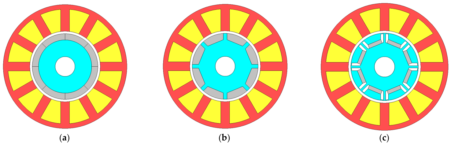
Various PM machine topologies have been proposed over the past few decades for a wide range of industrial applications, including electric vehicles, renewable energy systems, and aerospace technologies. One of the most popular PM machine topologies is the rotor-mounted PM machine, including, surface-mounted PM (SPM) machines, inset SPM machines, and interior PM (IPM) machines, as shown in Figure 1. It is noteworthy that SPM machines, shown in Figure 1a, feature non-salient rotor cores where arc-shaped PMs are affixed to the rotor’s surface. In such configurations, the electromagnetic torque is solely generated by the magnet torque. This is because the d- and q-axis inductances of SPM machines are identical, so no reluctance torque is generated. In contrast, both the inset SPM machines [see Figure 1b] and the IPM machines [see Figure 1c] exhibit a certain level of magnetic saliency, i.e., the difference between d- and q-axis inductances, resulting in reluctance torque [6]. As reluctance torque is generally less expensive to generate because it does not rely on expensive high-performance rare-earth magnets, inset SPM and IPM machines can potentially achieve a similar torque output while requiring less magnet material. This reduced magnet consumption can lead to a lower overall system cost.
Numerous research has undertaken a comparative study between SPM and IPM machines. In [7], it was highlighted that IPM machines exhibit better overload capabilities compared to SPM machines, both at low and high speeds. Notably, IPM machines achieve substantial reductions in PM losses, especially under high-speed conditions. This is mainly because the magnets in IPM machines are embedded within the rotor iron core, which provides magnetic shielding from the harmonic fields generated by both the permanent magnets and the armature MMF. As a result, the eddy-current losses in the magnets are significantly reduced. This assertion was corroborated by [8], which also acknowledged that while SPM machines tend to generate higher PM losses, they achieve a notable reduction in iron losses, leading to higher efficiency. Ref. [9] noted that SPM machines experience additional copper losses during flux-weakening operation at high speed. This is mainly due to the relatively low d-axis inductance of SPM machines, which requires a larger d-axis current to achieve the same level of flux weakening as in an IPM machine. Consequently, the copper losses increase during flux-weakening operation. On the other hand, ref. [10] emphasized the advantage of SPM machines, particularly their better dynamic responses and fault-tolerant capabilities, mitigating unbalanced magnetic forces, particularly in the presence of rotor eccentricity. However, a concern with SPM machines pertains to PM separation due to centrifugal forces under high-speed conditions. This is mainly because the magnets are typically bonded to the outer surface of the rotor. Under high-speed operation, the resulting centrifugal forces can cause the magnets to detach, potentially damaging the rotor. However, this issue can be mitigated by incorporating a rotor sleeve to provide additional mechanical support [11]. Meanwhile, IPM machines face more serious mechanical stress, as noted in [5], since their rotor iron bridges are subjected not only to centrifugal forces, but also to magnetic forces generated by the magnets. In contrast, ref. [12] showed that SPM machines can achieve higher torque density due to lower magnet leakage flux, while lower vibrations and acoustic noise due to smoother air-gap flux density distribution and more uniform effective air gap. Additionally, ref. [13] proposed that the SPM machines have smaller phase voltage distortion, as well as lower torque ripple than IPM machines, generally due to lower local saturation. In [14], a comparison between SPM and IPM machines using large-scale 7MW PM generators was conducted, and the authors concluded that SPM machines offer advantages in terms of reduced weight and cost, as well as improved demagnetization withstand capability, again due to lower d-axis inductance.
IPM machines provide more degree of freedom for machine designs when it comes to rotor structures, a factor that affects several important EM characteristics. These characteristics include torque density, cogging torque, and torque–speed range. Thus, different IPM machines can be implemented to meeting various requirements during industrial applications [6]. Evolving from basic concept of flat magnets [15], as shown in Figure 1c, IPM machines have developed into a diverse array of rotor configurations. These various rotor configurations and their associated advantages are listed in Table 1. Remarkably, certain IPM machine designs are capable of achieving exceptionally high reluctance torque, often reaching values in the range of 40% to 50% or even higher of the total torque [15,16]. These machines typically employ IPM rotors with multiple magnet layers per pole, which increase the difference between the d-axis and q-axis inductances, thereby enhancing the reluctance torque component. It should be noted that modifying the rotor structure alone is often insufficient to maximize reluctance torque; the rotor design must be complemented by an appropriate stator winding configuration. For example, although fractional-slot concentrated windings generally exhibit a lower saliency ratio and may not exploit reluctance torque as effectively as optimized integer-slot distributed windings. A similar phenomenon is observed in sensorless control applications, where the saliency ratio of fractional-slot concentrated-winding IPM machines is often close to unity, limiting the effectiveness of high-frequency signal injection methods. Nevertheless, despite these limitations, the combination of high torque density, wide constant-power speed range, and reduced permanent-magnet material requirements has contributed significantly to the widespread adoption of IPM machines, particularly in electric vehicle applications.

2.2. Stator Mounted PM Machines

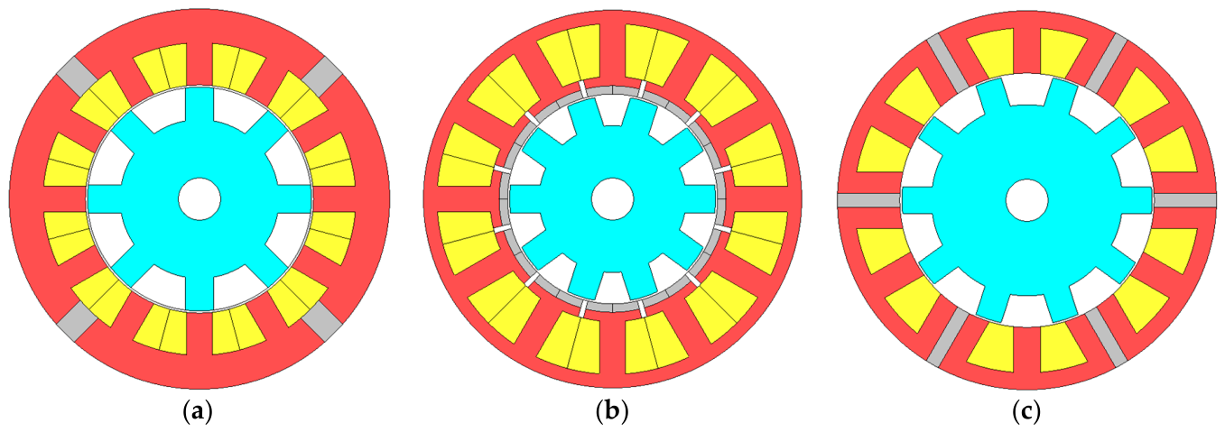
In addition to the rotor-mounted PM machines, various stator-mounted PM machines have seen significant development, including the double salient PM (DSPM) machines, the flux-reversal PM (FRPM) machines, and the flux-switching PM (FSPM) machines, and their topologies are shown in Figure 2. In contrast to the rotor-mounted PM machines, where the PMs are situated on the rotor, stator-mounted PM machines place windings and PMs on the stator, with the rotor primarily consisting of iron core. This simplified rotor structure results in enhanced robustness and reliability, especially in high-speed applications. As highlighted in [26], stator-mounted machines offer improved thermal performance. This improvement arises from the fact that dissipating heat from the rotor for rotor-mounted PM machines is a challenge due to the limitation in the poor thermal conduction within the air-gap region.
All three types of stator-mounted PM machines exhibit distinctive characteristics, determined by the location of their PMs. For example, the DSPM machine [see Figure 2a] produces unipolar flux linkages—that is, as the rotor rotates, the polarity of the phase flux linkage does not change. Consequently, its phase EMF is significantly lower than that of the other two stator-mounted PM machines, which exhibit bipolar flux linkages. This results in lower torque and power density for DSPM machines compared with their counterparts. The FRPM machine [see Figure 2b], to some extent, similar to the SPM configuration, has magnets placed adjacent to the air gap and mounted on the surface of the stator teeth. Due to this arrangement, the magnets are typically small and therefore more susceptible to demagnetization. In contrast, the FSPM machine [see Figure 2c] overcomes these limitations, as its magnets are sandwiched between stator segments, which act as magnetic shields and prevent demagnetization during the flux-weakening operation. Furthermore, owing to the flux-focusing effect and bipolar flux linkage, the FSPM machine generally exhibits the highest torque and power density among stator-mounted PM machines, although its relatively high magnet usage remains a concern.

3. Modular PM Machines

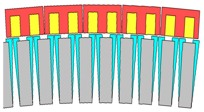
In addition to the advances in conventional PM machines discussed in Section 2, various stator and rotor configurations, particularly those incorporating modular (also referred to as segmented) designs, have been developed to further enhance machine performance while simplifying manufacturing and assembly processes. For example, Spooner et al. [27,28,29] introduced a new machine topology, involving a modular arrangement of stator and/or rotor, as shown in Figure 3, for a 166-pole/180-slot radial-field PM machine. Another study on a modular PM machine featuring both segmented stator and rotor structures was reported in [30]. However, the flux gaps introduced in the modular rotor are located directly within the main magnetic flux path, resulting in an increased effective air-gap length and consequently degraded torque performance. Despite these drawbacks, these modular designs are specifically implemented in generators with power ratings more than 1 MW. In contrast to the non-modular, continuous core designs, modular configurations offer distinctive advantages in terms of assembly and maintenance. Moreover, these modular designs have the potential to reduce both the machine’s mass and its active length.
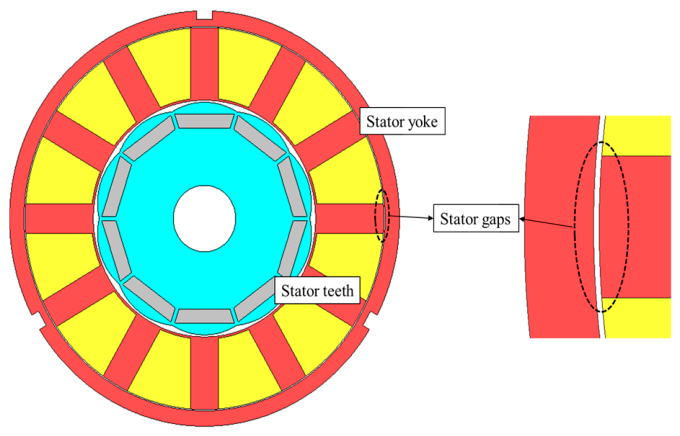
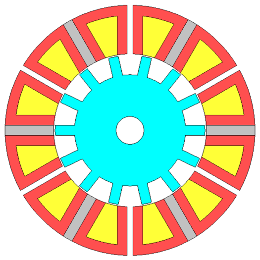
Another modular stator structure was explored and presented by Zhu et al. in [31]. A closed-slot stator with segmented teeth and yoke is implemented for a 10-pole/12-slot IPM machine as shown in Figure 4. Additional stator gaps between stator teeth and yoke with nonuniform gap width are introduced due to manufacturing tolerances. This topology effectively minimizes the cogging torque, which is a primary contributor to torque ripple, while having a negligible influence on the back-EMF waveform. The concept of modular technology extends to the stator design of FSPMs [32,33]. In this approach, the PM is selectively removed from alternate stator teeth, as shown in Figure 5. Research findings revealed that, the modular stator exhibits significantly enhanced fault-tolerant capability but comes at the cost of reduced power density. However, by maintaining the same PM volume, it becomes possible to achieve higher torque and power density in this design [34]. Another modular stator surface-mounted PM machine employing E-core stator modules with surface-mounted PMs on the central teeth was reported in [35]. For a 12-slot/13-pole configuration, the introduction of flux gaps was found to increase the back-EMF and average torque by 21.6% and 7.1%, respectively. These improvements were attributed to the enhanced winding factor and flux-focusing effect resulting from the incorporation of flux gaps in alternate stator teeth.
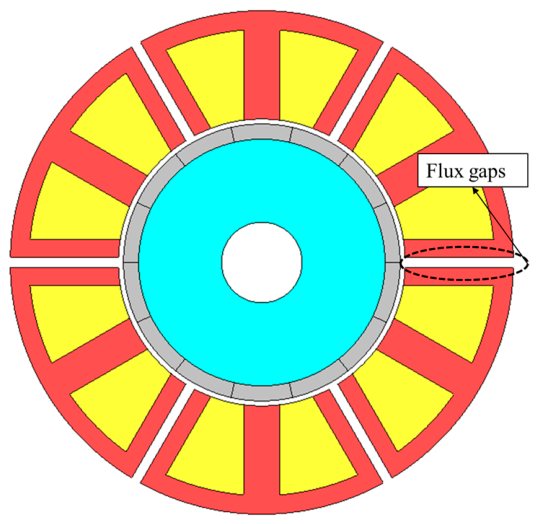
A number of studies by Li et al. [36,37,38,39,40,41,42] further investigated the influence of flux gaps on the electromagnetic performance of modular PM machines, as shown in Figure 6. Their research explores the influence of flux gaps on the electromagnetic performance of 12-slot/14-pole and 12-slot/10-pole SPM machines with stator modularity, as detailed in [38]. By inserting flux gaps in alternative stator teeth, this topology effectively prevents the flux of one phase from crossing into other phases. This configuration brings about significant reductions in mutual inductance (almost 0 mH at large flux-gap width of 5 mm) between phases, leading to enhanced fault-tolerant capabilities. The findings from this study reveal that the introduction of flux gaps in alternative stator teeth has several significant effects. It not only improves the winding factor to unity for fractional-slot concentrated windings, (more precisely, the pitch factor) but also enhances the open-circuit air-gap flux density. This is mainly because the introduction of flux gaps allows the coil pitch to be adjusted (by varying the flux-gap width) to match the pole pitch, resulting in a unity pitch factor while maintaining a unity distribution factor. In addition, the presence of flux gaps modifies the air-gap permeance; similar to a magnetic gearing effect, certain harmonic flux components are effectively converted into the fundamental component, thereby increasing the fundamental air-gap flux density. Additionally, it introduces an extra flux focusing effect for the machines, but only when their pole number (2p) is larger than the slot number (Ns). These threefold effects in modular machine with 2 p > N s result in higher torque and power densities that are more than 10% higher than those of their non-modular counterparts. It is noteworthy, however, that these threefold effects have a negative impact on modular machines with 2 p < N s . In such cases, flux defocusing, together with a reduced pitch factor and decreased open-circuit air-gap flux density, leads to a reduction in electromagnetic torque. Another analytical modelling study of a modular PM machine was reported in [43]. Unlike conventional modular machines employing E-core stator segments, this machine incorporates additional flux gaps within the wound stator teeth. However, these flux gaps do not extend through the entire tooth height, which is the case for the C-core modular stator; the tooth-tip region remains continuous and unsegmented. Consequently, they do not create slot openings, which distinguishes them from the flux gaps commonly found in most modular machine topologies. In other studies, the introduction of flux gaps in modular machines has been shown to improve demagnetization withstand capability [39]. Similar to its impact on torque and power density, flux gaps can also mitigate magnet demagnetization for the modular machines with 2 p > N s . In contrast, for modular machines with 2 p < N s , the introduction of flux gaps exacerbates magnet demagnetization.
Modular machines also exhibit improvements in vibrations and acoustic noise. A study referenced in [37] investigated the influence of flux gaps on machine vibrations and acoustic noise, revealing noteworthy findings. Despite the reduction in resonant frequency due to the stator modularity, the decrease in radial force and magnetic pressure within the air gap contributes to a reduction in vibrations by 71% and in the sound pressure level by 85%. A related study was reported in [44], which investigated the vibration characteristics and optimization of a novel E-core modular stator permanent magnet synchronous motor from the perspective of stator tooth modulation. Unlike the machine presented in [37], the E-core stator segments incorporate dummy slots in the stator teeth while retaining continuous iron bridges and windings, thereby enhancing the flux modulation effect. The use of dummy slots for flux modulation enhancement was also explored by Yu et al. [45] in a Vernier machine developed for electric vertical takeoff and landing (eVTOL) aircraft propulsion. Their results showed that the combination of dummy slots and flux gaps can further strengthen the flux modulation effect.
Li et al., as investigated in [36], have further formulated the design guidelines for fractional-slot multi-phase modular PM machines. Embracing stator modularity offers several advantages, including easing the manufacturing process, notably the winding process, and providing additional flexibility for cooling designs. Furthermore, the modular topology has the capacity to reduce the sub-harmonics of air-gap MMF, thereby mitigating their adverse impact on machine EM performance. These advantages of introducing flux gaps can be extended to multiphase machines, such as four-phase, five-phase, or higher-phase configurations. In another study on multiphase modular PM machines, Dajaku [46] investigated an 11-phase modular PM machine (with single-layer windings) and compared its performance with that of a conventional non-modular 12-slot/10-pole PM machine employing double-layer windings. The results demonstrated that the multiphase modular PM machine achieved a higher average torque while maintaining minimal torque ripple.
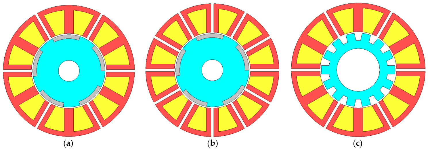
Research on the influence of flux gaps on SPM machines is not limited to a specific type of rotor structure. Similar findings have been established for other rotor structures. For instance, Zhou et al., as presented in [42], investigated two types of modular stators designed for consequent-pole PM machines. One design, as shown in Figure 7a, is referred to as the E-core stator, while the other, depicted in Figure 7b, is known as the C-core stator. Their findings have demonstrated that the E-core modular stator for consequent-pole PM machines contributes to enhancements in electromagnetic torque, increased machine efficiency, and improved flux-weakening capability. Conversely, the C-core modular stator design helps reduce the torque ripple, minimizing the on-load unbalance magnetic forces and enhancing the power factor. The consequent pole modular PM machine concept was further investigated in [47,48]. Both studies showed excellent electromagnetic performance improvement due to the introduction of flux gaps in either alternate stator teeth—E-core modular machine or in all stator teeth—C-core modular machine.
The literature also encompasses an analysis of iron losses in modular inset SPM machines, as detailed in [40]. The introduction of flux gaps has been shown to result in a substantial reduction in onload iron losses for these modular inset SPM machines. For example, for the 12-slot/14-pole modular inset SPM machine, its onload iron loss is reduced by more than 20% from 0 mm flux-gap width (non-modular) to 5 mm flux-gap width. In addition, the presence of flux gaps has also led to improvements (by >10%) in machine electromagnetic torque.
Stator modularity has also been applied to IPM machines [50,51,52]. The findings align with Li’s research, demonstrating that introducing flux gaps, also known as flux barriers by Gerling, results in the improvement of machine EM performance, particularly when the machine’s pole number is larger than the slot number. Stator modularity is not limited to PM machines either; it also offers advantages for SRMs [49,53,54]. Modular 12-slot/14-pole and 12-slot/8-pole SRMs were developed in [49]. It is found that, modular 12-slot/14-pole SRM exhibited a high average torque. Its reduced sensitivity to magnetic saturation in the back iron allows it to generate high torque under overload conditions. Furthermore, similar to stator modularity in PM machines, modular SRMs demonstrated lower iron losses and radial force compared to their non-modular counterparts.
In this section, various machines with different levels of modularity are reviewed, and their advantages are investigated and analysed, as listed in Table 2. In summary, all the reviewed literature consistently highlights several general advantages associated with the modular structure in machine design, which include:
  • Improved electromagnetic torque due to increased winding factor (by more than 3%).
  • Mitigation of mutual inductance (to almost 0 mH due to flux gap between adjacent coils), leading to improved fault-tolerant capability.
  • Simplified manufacturing process, including assembly and winding process.
  • Reduced machine maintenance and replacement costs.
  • Decreased overall machine weight by up to 10%.
However, several trade-offs must be considered in the design of such modular machines. For example, when flux gaps are introduced into alternate stator teeth, the iron section width of those teeth should be maintained to avoid excessive magnetic saturation. If the overall stator tooth width is kept unchanged, inserting flux gaps reduces the effective iron area in the affected teeth, leading to higher local saturation and reduced overload capability. Conversely, maintaining the same iron section width requires a reduction in the slot area, which results in smaller conductors (for a fixed number of turns) and therefore increased copper loss. For this reason, it is important to evaluate the average torque-to-copper-loss ratio, rather than average torque alone, when designing modular machines. The results in [38] indicate that although copper loss increases with the introduction of flux gaps, the average torque also improves. With proper design optimisation, it is possible to achieve lower copper loss for a given torque level.
Other issues, such as structural stiffness and manufacturing tolerances, also require careful consideration during the manufacturing and assembly of modular stator segments. One typical approach is to insert prefabricated stator segments with windings into corresponding slots on the inner surface of the housing. One example can be found in [38]. However, unlike conventional shrink-fit assemblies, the contact between the stator segments and the housing may be relatively loose, resulting in larger assembly tolerances and potential segment radial displacement. In a study by Ren et al. in [41], the impact of manufacturing (assembly) tolerances on segment radial displacement was comprehensively investigated. The analysis included back-EMF, on-load torque, cogging torque, and unbalanced magnetic force in modular SPM machines, in order to evaluate the tolerance of the machine to segment displacement. The results indicate that the modular structure, particularly for machines with 2p < Ns, is relatively insensitive to segment radial displacement.
In summary, although PM machines, particularly modular PM machines, offer distinct advantages over other types of electrical machines, their rotor- or stator-mounted permanent magnets are susceptible to irreversible demagnetization at elevated operating temperatures. This can limit their performance and reliability in high-power-density applications. To address this challenge, advanced thermal management has become increasingly critical, as effective cooling can extend machine lifespan, further improve torque and power density, and enable PM machines to fully realize their potential in demanding applications such as electric vehicles, wind power, and aerospace systems.

4. Thermal Managements for PM Machines

The preceding sections have analysed a number of studies concerning the designs and investigations of modern PM machine topologies. These studies are primarily focused on improving machine EM performance, such as increasing torque and power density, minimizing machine size and mass, and improving the efficiency. However, a notable constraint in the pursuit of improved EM performances lies in the realm of thermal management. Elevated temperatures, beyond the desired range, lead to irreversible damage for machines. The damage includes derating of power electronics components, irreversible demagnetization of PMs, and the deterioration or expedited aging of wire insulation. As a rule of thumb, a 10 °C increase in operating temperature reduces the lifespan of winding insulation by half, with a similar effect observed on bearing life.
Cooling technologies adopted for machine thermal management can be categorized into two main aspects: passive cooling methods and active cooling methods. Passive cooling methods work without additional pumps or devices to circulate coolant. Some of them aim to improve heat conduction within machines, particularly between the end-windings and the machine housing. Others focus on improving heat convection and radiation at the surface of machine components or its external surfaces. On the other hand, active cooling methods represent another category of cooling technology. They involve the incorporation of additional pumps or devices to establish either a close-loop coolant circulation or throughflow ventilation for machine cooling. This section reviews and compares the existing literature on cooling technologies for both conventional and modular PM machines. It is worth noting that all conventional cooling methods could be applied to modular PM machines. However, owing to their modular structure, modular PM machines can also accommodate novel cooling strategies that further enhance their thermal performance.

4.1. Passive Cooling Technology

4.1.1. Natural Passive Cooling

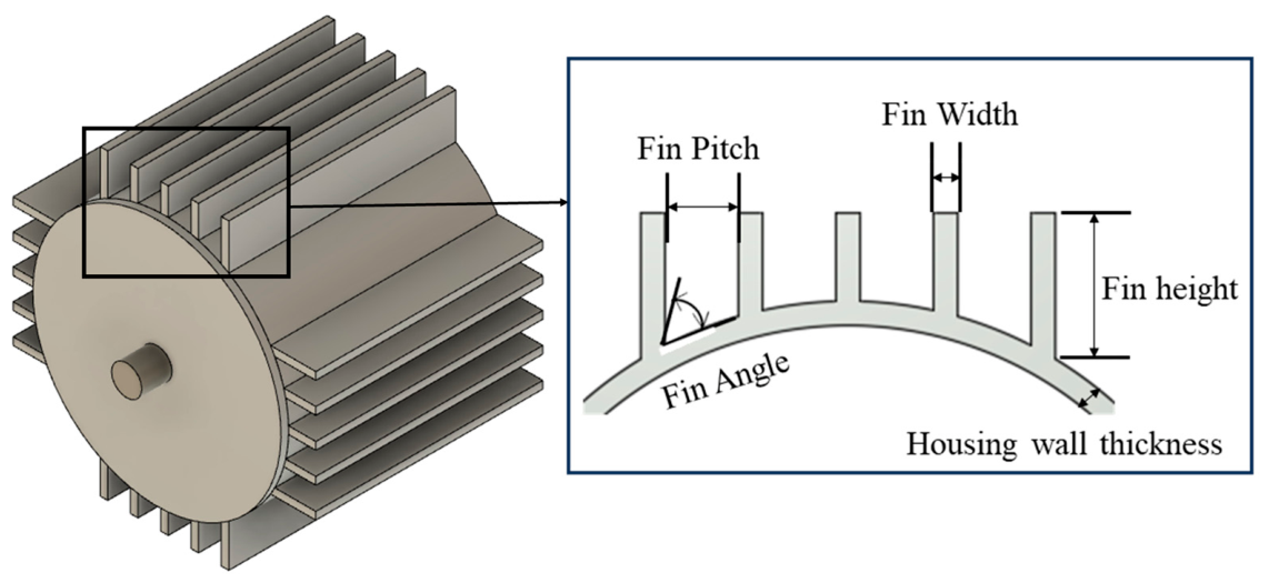
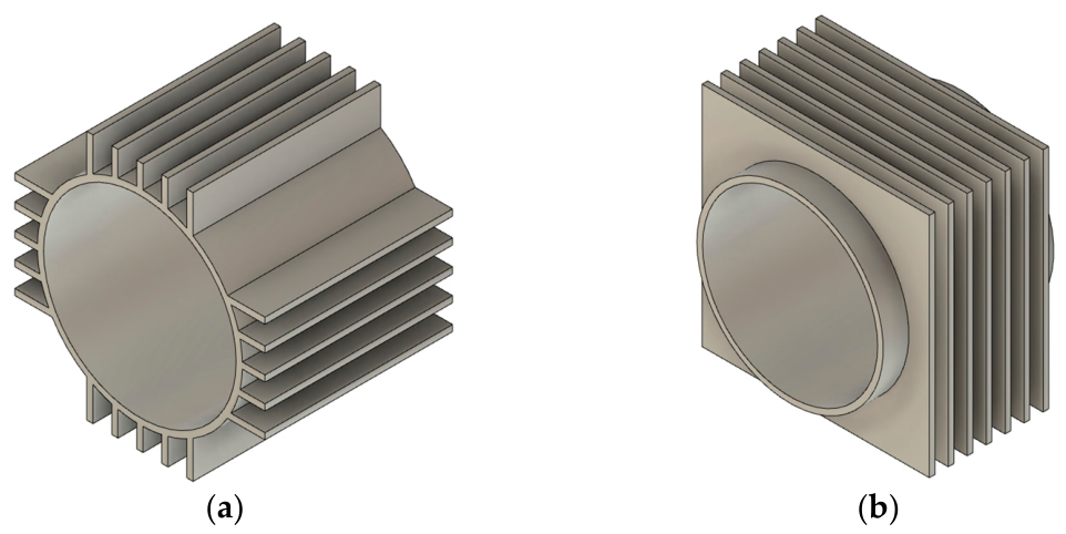
The outer surface of the machine housing serves as the primary path for transferring heat from the inner components to the surrounding environment. The objective of the natural passive cooling method is to optimize this mechanism to improve the rate of heat dissipation. Finned housing, as shown in Figure 8, employs cooling fins on the frame to enlarge the contact surface area of housing and enhance the convection coefficient. The cooling efficiency of finned housing is affected by different parameters, including the number of fins, fin width, fin height, fin pitch, fin angle, etc. These parameters play a crucial role in determining the effectiveness of finned housing.
A study on optimizing the finned housing was conducted in [55]. In this study, 2600 cases of finned housing with various parameters were compared. It was found that the finned housing with higher number of fins tended to exhibit better cooling efficiency. Specially, the study indicated that finned housing with nine fins exhibited the best cooling efficiency in this research. A further increase in the number of fins cannot boost the cooling efficiency. It is worth noting that further increasing the number of fins did not yield enhanced cooling efficiency, as this led to a larger portion of the cooling channel being obstructed. Furthermore, this study highlighted the importance of the outer contour of the finned housing, suggesting that it is better to follow a circular shape. Deviating from a circular shape may result in significant temperature differences within finned housing, potentially leading to additional heat flow from the inner cooling circuit.
The orientation of fins is also important for designing a finned housing. In a study conducted by [56], two orientations of fins were investigated and compared: axial longitudinal fins and radial fins, as shown in Figure 9. For both fin configurations, an increase in fin height led to lower housing temperature. Moreover, a comparison of housing temperatures for these two designs under different housing masses demonstrates that radial fins exhibit lower housing temperatures when compared to axial longitudinal fins.
It is essential to highlight that the orientation of fins should be carefully considered to avoid disrupting the airflow [57]. Consequently, the cooling efficiency of finned housing with axial longitudinal fins, radial fins, or other configurations will be different under different operating conditions. The finned housing is commonly integrated into totally enclosed fan-cooled (TEFC) machines [58,59,60]. In the TEFC machines, axial airflow is prevalent, making axial longitudinal fins a more attractive choice due to their compatibility with axial airflow.

4.1.2. Potting Materials

Particular attention must be given to addressing the two primary areas of concern with electrical machines. One is the rotor, especially in rotor-mounted PM machines, where the issue arises due to a poor heat transfer rate in the air-gap region. The other is the end-windings, which characterized by poor heat transfer path between the end-windings and the housing [61].
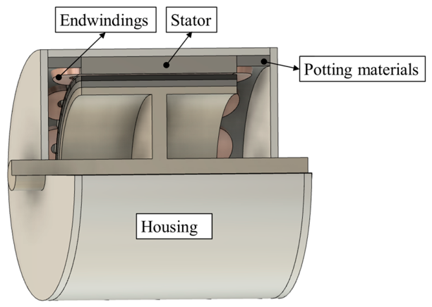
To improve the heat transfer in end-winding regions, potting materials have been employed to serve the purpose of replacing the air within the end space as shown in Figure 10. The potting material establishes highly effective heat conduction between the end-winding and the housing, a process that would be notably inefficient if air were retained. The main reason is the significantly higher thermal conductivity of potting materials in comparison to air. Moreover, low air velocity and limited turbulence around end-windings render it less effective at facilitating heat convection. It is worth noting that, the cooling efficiency of potting materials is impacted by its thermal conductivity and density. Additionally, the choice of potting materials should consider the allowable temperature limits of these materials. A summary of these properties for various potting materials is listed in Table 3.
Moreover, various liquids, including liquid hydrogen (LH), liquefied natural gas (LNG), or liquid nitrogen (LN2) [62], as well as nanofluids [63], ferrofluid (also known as thermomagnetic liquid) [64,65], and phase change materials (PCMs) [66] can also be introduced in end-space regions to improve the heat transfer rate from end-windings to housing. Compared with air, these liquids can provide higher conductive heat transfer. Additionally, the presence of gravity significantly aids in establishing a more efficient coolant circulation when employing liquids.
It is worth noting that, amongst these coolants, LH, LNG and LN2 stand out for their ability to provide much lower coolant temperatures, specifically −253 °C, −161 °C and −196 °C, respectively. This enables highly effective cooling systems, particularly in scenarios such as in superconducting machines where maintaining low operating temperatures is crucial. Furthermore, it is worth noting that, ferrofluids have thermomagnetic convection to create a novel coolant circulation system. This phenomenon occurs when ferrofluids experience a magnetic body force in the presence of magnetic field gradients or discontinuities, enabling efficient heat dissipation and cooling. These represent emerging cooling technologies, and considerable research is currently underway to develop them into commercially viable solutions for a range of industrial applications.
Table 3. Physical properties of potting materials.
MaterialsThermal Conductivity ( W / m / K )Density ( k g / m 3 )Allowable Temperature ( ° C )Reference
Air0.0261.185-[67]
Lord SC-3203.22810-[68]
AIN Compound3.82470-[69]
Stycast 27621.37--[70]
Electrolube ER22180.281160−50 °C to 150 °C[71]

4.1.3. Back-Iron Extension and Heat Guides

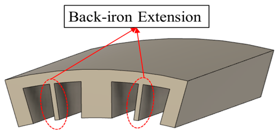
The previous section focused on improving the heat transfer from end-windings to the housing, primarily aiming to reduce the end-winding temperature. On the other hand, other cooling technologies are focused on reducing the temperature of the active coils. Back-iron extension is one of these cooling technologies, as shown in Figure 11 [72]. This method offers a simple and cost-effective means to reduce winding temperature, particularly the active coil. The extended back-iron enhances the heat transfer rate from the coils to the stator. However, it is important to consider its potential influence on slot fill factor and end-winding length. The research in [72] demonstrated a significant temperature reduction, with a remarkable decrease of 26.7%.
A similar structure is proposed and investigated in [73]. In contrast to the back-iron extension, the approach utilizes detachable thermal conductive heat guides (HGs) within the slot. There are two types of HGs: passive type and active type. The mechanism of the passive HGs is similar to the back-iron extension by improving the heat dissipation from windings. However, due to their detachability, they offer advantages in terms of ease of manufacture, assembly, and maintenance. The incorporation of additive manufacturing, commonly known as 3D-printing, is introduced to fabricate different HGs. This technology allows for achieving a lighter weight, reduced power loss, and improved heat transfer rate in the HG design. The active type of HGs is more like a heat pipe, which provide a cooling channel for forced cooling systems [74,75].
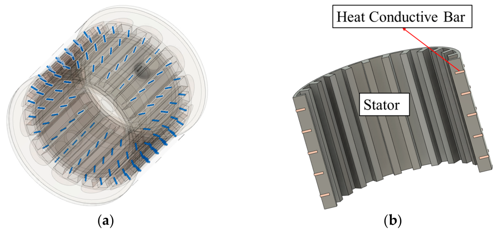
These HGs can be employed not only within the slot but also inside the stator, as shown in Figure 12 [76]. In this design, a highly thermal conductive bar, which made of copper as seen in [76], is embedded through the stator iron core. This arrangement allows for more effective transfer of heat generated in stator teeth to the external frame, usually embedded with a water jacket. The placement of these thermal conductive bars aligns with the magnetic flux, resulting in negligible eddy-current losses. However, it is worth considering potential mechanical reliability problems associated with this design.

4.2. Active Cooling Technology

Passive cooling technologies improve machine thermal performance without requiring an external power supply. However, compared with active cooling methods, passive approaches generally provide lower cooling capability, as outlined in Table 4. Consequently, active cooling is often necessary in high torque- and high-power-density applications, such as electric vehicles and wind power systems. In active cooling system design, the physical properties of the coolant must be carefully considered to achieve an effective balance between cooling performance, system volume and mass, and the maximum pressure or flow rate that can be supplied by external pumps or auxiliary devices. The physical properties of several commonly used coolants for active cooling of electrical machines are summarized in Table 5. The following sections will review established active cooling systems widely used across various industries, as well as several emerging cooling technologies for electrical machine applications.

4.2.1. Forced-Air Cooling

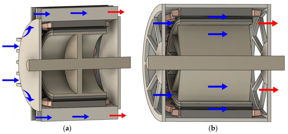
Force air cooling technology employs a fan or a blower to create airflow. The airflow can either pass through the machine outer frame, namely totally enclosed fan-cooled (TEFC) machine, or flow through the machine internal components, as observed in a throughflow ventilation machine. The airflow patterns for these two machine configurations are shown in Figure 13. In comparison to the passive cooling systems, the forced-air cooling systems significantly enhance heat convection. Various machine designs utilize fans in different locations to generate different airflow patterns. For example, the enclosed fan cooled (EFC) machine implements a fan outside the totally enclosed machine, as shown in Figure 13a [60,81,82,83,84]. It achieves a significant enhancement of convection coefficient at the outer surface of the frame. However, the cooling efficiency of the EFC machines is constrained by the heat transfer within the machines.
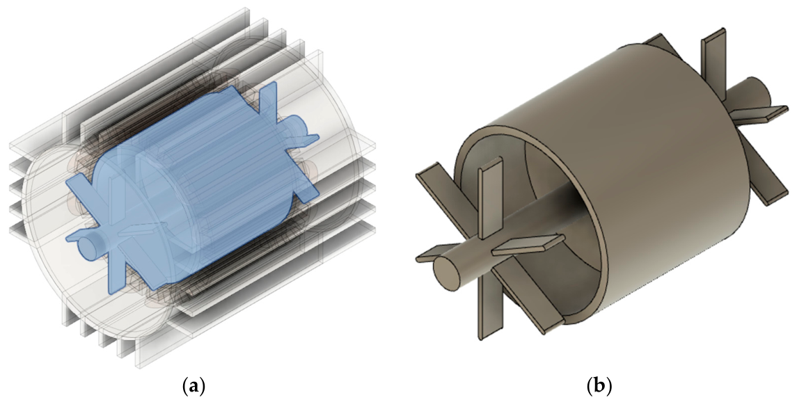
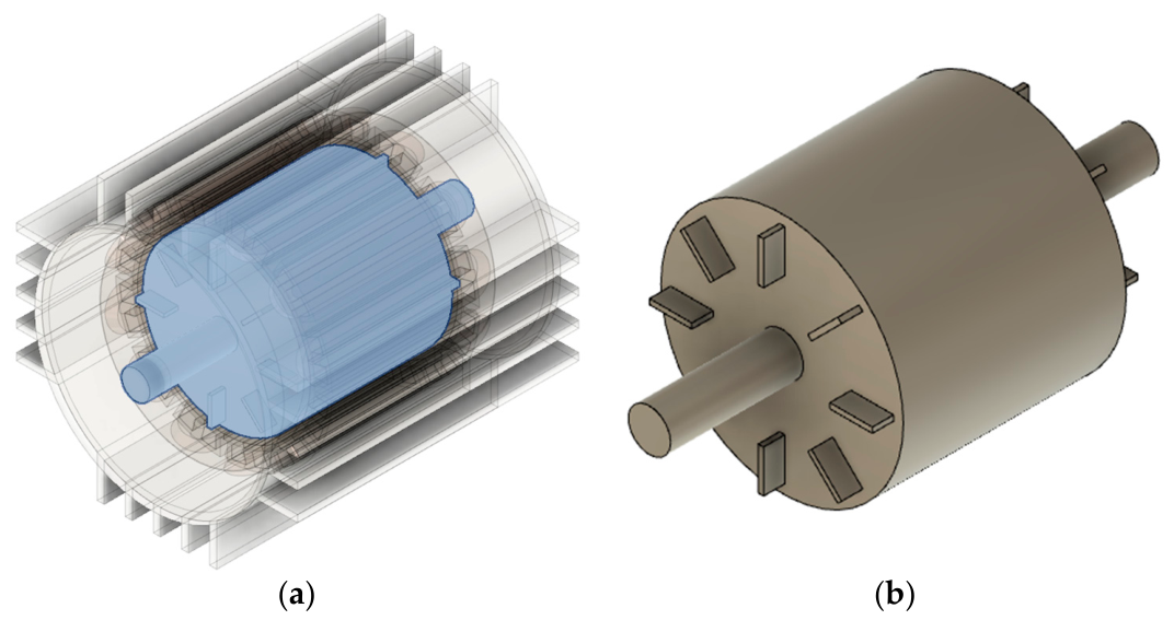
To maintain the isolation of the machine from surrounding debris while enhancing the internal heat transfer rate, inner fan blades are employed and mounted on the shaft in the EFC machines, as shown in Figure 14 [57,85]. In addition, wafters can also be integrated onto the rotor, as shown in Figure 15 [86,87,88]. Both shaft mounted fan blades and rotor-mounted wafters establish new air circulation within the machines, improving heat transfer from the inner components to the housing frame. However, it is worth noting that the cooling efficiencies of these designs are limited by the machine rotor speed and they are not particularly effective at relatively low rotor speeds.
The EFC machines offer advantages such as reduced acoustic noise and lower maintenance cost [85]. However, the totally enclosed frame design constrains the effectiveness of forced cooling systems, as the overall heat dissipation still depends on the cooling mechanism applied to the outer surface of the housing. To address this limitation, a new machine configuration, known as the throughflow ventilation machine, has been introduced [89,90], as shown in Figure 13b. In throughflow ventilation machines, air is continuously drawn from the ambient environment into the machines without recirculation. However, this exposure to the surrounding environment means that ventilated machines are vulnerable to contaminants. To mitigate this issue, inlet and outlet grills and guards are commonly used to shield ventilated machines from direct exposure to surrounding particles and moisture [57]. Nevertheless, grills and guards raises concerns regarding potential reductions in cooling efficiency, increased system flow resistance, and fan losses [91].
In addition to air, other gases, such as hydrogen and helium, can also be employed as coolants in forced cooling systems with machine configurations similar to those discussed in this section. These gases provide better cooling efficiency compared to air, primarily because of their lower density, reduced dynamic viscosity, and higher heat conductivity, as listed in Table 5 [80].

4.2.2. Indirect Forced Liquid Cooling

Liquids are another category of fluid in machine cooling. Typically, liquid cooling systems tend to offer better cooling efficiency than gas cooling systems, as indicated in Table 4. This achievement is mainly attributed to the higher thermal conductivity of liquid. Indirect forced liquid cooling technology is widely used not only for its good cooling efficiency but also because it prevents direct contact between the coolant and machine components, thereby avoiding potential corrosion issues. In addition, adopting a totally enclosed design allows the machine to achieve high ingress protection (IP) ratings, such as IP67 or IP68, ensuring effective protection against environmental factors and contaminants.
Housing water jackets are commonly employed in automotive traction motors [92,93,94,95]. The heat generated in the windings and stator is conducted to the cooling housing and transferred to the surrounding environment via the coolant within the water jacket. This approach significantly improves convection coefficient at the housing surface, leading to a reduction in machine temperature. The cooling efficiency of a housing water jacket is related to the properties of the coolant employed. The ethylene Glycol based water (EGW) are typically implemented for traction motors [96]. In addition, for aerospace applications [97], aviation turbine fuel and lubricating oil may be implemented as coolants, considering the specific operating conditions of these applications.
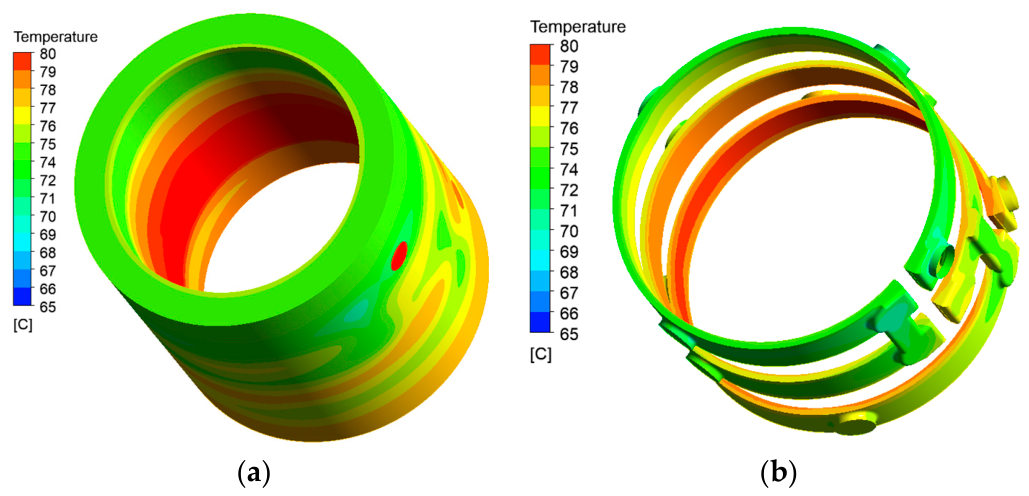
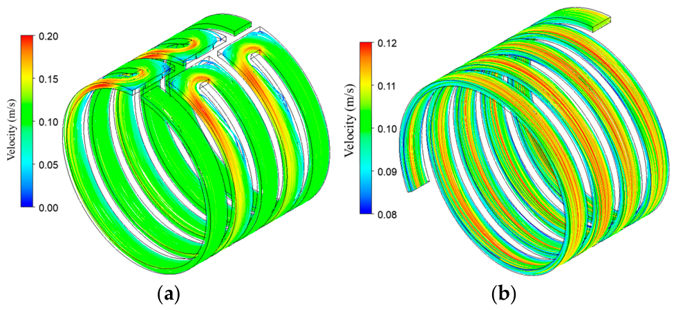
The cooling efficiency of a housing water jacket is also influenced by the design of the flow channel. One of the flow channel designs is the circumferential flow design, which is employed in the Nissan-leaf electric motor. In this design, circumferential flow channels are connected by axial channels, and when combined with external flow channels and heat exchanger, a closed-loop coolant circulation is established to effectively reduce machine temperature. It is worth noting that, in this system, the convection coefficient is non-uniform, and there is a non-uniform temperature distribution of coolant and housing, as shown in Figure 16.
The concept of spiral flow channel was proposed in [96]. Compared with a circumferential flow channel, utilizing a spiral flow design leads to a noticeable reduction in flow resistance. For instance, when both designs are subjected to a water flow rate of 6.5 L/min, the pressure loss for circumferential flow channel amounts to 103 Pa, while the pressure loss is reduced to 61 Pa for the spiral flow channel. The bends in the circumferential flow channel result in higher coolant velocity in the bending area, as shown in Figure 17. Nevertheless, it is important to note that these bends can also introduce additional pressure losses [91].
The housing water jacket has a significant ability to improve the rate of heat dissipation from the machines to the ambient environment. However, the poor heat transfer rate from the end-windings to the housing frame can limit the overall cooling efficiency. Particularly, the end-winding is typically the region where the hottest spots are located. To address this challenge, the passive methods discussed in Section 4.1 for enhancing heat transfer within the end space can be combined with water-jacket cooling to improve the overall cooling efficiency of the machine. Moreover, some active cooling technologies have also been developed to achieve the same purpose.
Inserting a dedicated liquid cooling pipe into the end-windings offers a direct means to efficiently transfer the heat generated by the end-winding out of the machines. Reference [98] proposed a new cooling technology that combines this direct end-winding cooling method with a housing water jacket. This combined system has been demonstrated to significantly reduce machine temperature, particularly in the end-winding regions. Different materials for the dedicated liquid cooling pipe, including metallic pipe, thermoformed polymer, and silicone rubber, have been investigated and compared. The comparisons reveal that silicone rubber exhibits the best cooling efficiency among these materials. This superiority can be attributed to the expansion of the silicone rubber pipe, when carrying pressurized fluid.
The additive manufactured (AM) heat guides discussed in Section 4.1.3 are similar to the cooling effect of heat pipes, connecting to an external pump or device to provide effective cooling efficiency. For instance, a polycarbonate aluminium flake (PC-AL) heat pipe, serving as a direct heat exchanger, can be placed within a slot to improve the heat dissipation of windings [74]. Moreover, heat pipes can be placed inside stator slots, the shaft, rotor, end-windings, and end-region cavities [75].
Heat dissipation in machine’s rotating components is more critical than in stationary components, especially in the rotor-mounted PM machines. In these machines, PM eddy-current losses are conducted through the shaft and dissipated primarily by air-gap convection. To enhance heat dissipation from the shaft, a hollow shaft topology is employed [99,100,101], resulting in a significant temperature reduction due to this shaft cooling method. In addition, the rotation of the shaft introduces additional coolant velocity in the tangential direction, caused by the rough wall and coolant viscosity. As the rotation speed increases, the convection coefficient at the shaft surface is enhanced [101].
It should be noted that the indirect forced liquid cooling methods presented in this section generally lower machine temperatures and minimise corrosion risks. Nevertheless, challenges related to coolant leakage and the maintenance of the machine and its cooling system require careful consideration.

4.2.3. Direct Forced Liquid Cooling

In contrast to indirect forced liquid cooling systems, direct forced liquid cooling technologies bring the coolant closer to the heat sources, typically the stator iron losses and winding copper losses. Thus, higher cooling efficiency is expected from direct forced liquid cooling systems.
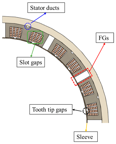
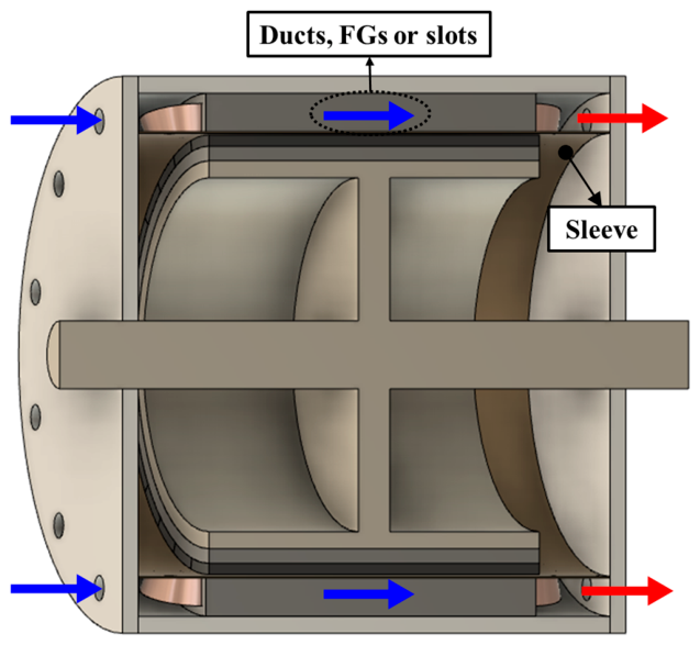
Semi-flooded cooling is one of the direct forced liquid cooling methods, in which the coolant is forcibly directed through the components, typically the stationary components such as the stator iron core and windings. This approach involves several flow pathways, as shown in Figure 18. These flow paths include annular gaps between the stator and the housing [102], stator axial ducts [103], gaps between each conductor in slots [104], gaps in tooth tips for semi-closed slots [103], and flux gaps (FGs) in machines with stator modularity [105]. The latter will be detailed further in Section 4.3. It is worth noting that the viscosities of the coolants employed in semi-flooded cooling systems are typically higher than that of air. To prevent increases in friction losses and coolant leakage, a sleeve is often employed to separate the machine into an oil-flooded stator part and an oil-free rotor part, as shown in Figure 19.
Semi-flooded cooling achieves significant temperature reductions in machine stationary components. However, it presents a challenge in cooling the rotating components, particularly the PMs in rotor-mounted PM machines, as they cannot be directly cooled by the flooded coolant. To address this issue, the concept of a totally immersed electrical machine was investigated in [106]. In this approach, both the rotational and stationary components are directly cooled by coolant. However, it is important to note that this introduces additional friction losses. To make this concept work effectively, the coolant must be an electrically non-conductive and non-magnetic material with a high specific heat capacity and high thermal conductivity. In addition, to mitigate the influence of increased friction losses, the viscosity of the coolant should be low.
Oil spray and oil jets represent another form of direct forced liquid cooling [107,108,109]. For these cooling methods, oil is atomised and breaks into droplets, which are then impinged onto the surfaces of the end-windings. The impinging oil mitigates the thermal resistance and improves the heat transfer rate between the end-windings and the housing. The impingement heat transfer contributes to the high convection coefficient observed in oil-spray and oil-jet cooling systems [110]. However, it is worth noting that oil atomisation requires much higher pumping pressure than other active cooling technologies. This high-pressure atomised oil raises concerns about the potential damage to the winding insulation [96]. Careful consideration of the design and operational parameters is crucial to mitigate these concerns.

4.3. Cooling Technology for Modular PM Machines

4.3.1. Rotor-Mounted Modular PM Machines

As reviewed in Section 3, PM machines incorporating stator modularity have been extensively developed and investigated because of their advantages in enhancing electromagnetic (EM) performance. However, the introduction of flux gaps in these modular machines not only affects the EM field distribution but also provides additional opportunities and design flexibility for thermal management and cooling integration.
In a study by Zhou et al., a ventilation cooling system (see Figure 18 and Figure 19 when FGs are used) was implemented in a consequent PM machine with stator modularity [111]. They investigated the heat transfer characteristics and flow profiles, and found that the presence of flux gaps enhances convective heat transfer, resulting in a significant reduction in machine temperature from 91 °C in the non-modular machine to 83 °C in the modular counterpart at a flow speed of 2.5 m/s. This reduction in winding peak (hot-spot) temperature is mainly attributed to the increased heat transfer surface area introduced by the flux gaps. For example, in the non-modular machine investigated in [111], the coolant primarily flows through the air gap, and the corresponding stator-side air-gap surface area is approximately 8953.5 mm2. In contrast, for the modular machine with a 2 mm flux-gap width, an additional heat transfer surface area of about 12,900 mm2 is introduced. This corresponds to an increase of approximately 145%, which contributes to the observed temperature reduction. In addition, the presence of flux gaps reduces flow resistance for the whole machine, leading to lower pressure losses by as much as 70% compared to the non-modular machine. This reduction is also attributed to the presence of flux gaps. For example, in the non-modular machine, the coolant channel (i.e., air gap) has a cross-sectional area of 179 mm2, whereas the introduction of flux gaps in the modular machine provides an additional cross-sectional area of 258 mm2. This corresponds to an increase of approximately 145%. In addition to the forced-air cooling, the semi-flooded cooling system can also benefit from the introduced flux gaps for the same reason, resulting in much lower pressure losses and reduced machine temperature [105].
Similarly, a new ventilation cooling using flux gaps and rotor ducts in a modular SPM machines as extra cooling channels have been proposed in [112]. In this method, cooling air is pumped into the stator flux gaps and rotor ventilation ducts to enhance heat dissipation. The introduction of airflow through the modular structure leads to a considerable reduction in machine temperature, e.g., >10 °C reduction in maximum winding temperature compared to non-modular machine design. This is mainly because the stator flux gaps not only create additional coolant flow paths that significantly alter the internal airflow distribution but also increase the heat exchange surface area between the machine and the cooling medium, thereby improving the overall heat transfer capability.
In addition to forced-air cooling using flux gaps as cooling channels, further research has extended this concept to forced liquid cooling. In [113], a semi-flooded cooling approach was proposed for modular machines to enhance their thermal performance and increase power density. In this configuration, a polyether ether ketone (PEEK) sleeve is employed to isolate the stator from the rotor, while coolant oil is circulated around the stator windings and iron core to achieve substantial temperature reduction. This design also prevents coolant leakage into the rotating components, thereby avoiding additional friction losses. 3D computational fluid dynamics (CFD) results demonstrated that, owing to the significantly higher thermal conductivity and density of the coolant compared with air, the semi-flooded cooling strategy can reduce the end-winding temperature of the modular SPM machine by approximately 80 °C compared with that of a non-modular machine.
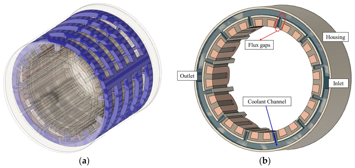
Nollau et al. established a new water jacket for machines with stator modularity [114]. The coolant channel is extended into flux-gap region, as shown in Figure 20. The bent channel design in the flux gaps not only increases the cooling area but also induces turbulent flow, leading to 10% higher cooling efficiency than a standard water jacket. These innovations demonstrate how flux gaps in stator-modular machines can significantly improve cooling and overall machine performance.
It is worth noting that the cooling methods discussed above for modular PM machines use conventional coolants, either air for forced-air cooling or liquid for semi-flooded or water-jacket cooling. A somewhat unconventional magnetic liquid, i.e., ferrofluid, has also been proposed as a coolant for a modular PM machine in [115]. In this work, ferrofluid is injected into in the cavity around the end-windings and flux gaps in alternate stator teeth. The multiphysics analysis based using COMSOL software (Multiphysics 6.0) package presented in this study demonstrates that flux gaps affect the thermal behaviour of the modular PM machine through two main mechanisms. First, the gravitational effect enables greater self-driven circulation of the coolant through the flux gaps, enhancing heat transfer to the housing and lowering the machine temperature by approximately 5 °C when the flux-gap width is 2 mm. Second, the magnetic body force, also referred to as the thermomagnetic effect, significantly improves cooling performance in non-modular machines. However, its effectiveness is slightly reduced in modular machine configurations because the thermomagnetic effect adversely influences the self-circulation of the ferrofluid within the flux gaps that is induced by gravity.

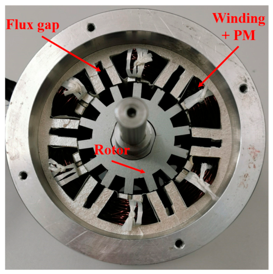
4.3.2. Stator-Mounted Modular PM Machines

In the previous section, the flux gaps were shown to be highly effective in cooling the stator components. However, in rotor-mounted permanent magnet (PM) machines, the PMs are located relatively far from the cooling channels within the flux gaps (separated by an air gap) and are therefore cooled less effectively than the stator windings. To overcome this limitation in PM thermal management, researchers have proposed both forced-air and liquid-cooling approaches for stator-mounted modular PM machines, as shown in Figure 21. In these configurations, the PMs and windings are both positioned on the stator, allowing them to benefit from a similar cooling effect provided by the coolant flowing through the flux gaps located in alternate stator teeth.
Zhang et al. proposed a forced-air cooling method for a 12-slot/10-pole modular FSPM machine in [116]. To evaluate the effectiveness of this cooling approach, 3D CFD simulations were conducted for FSPM machines with flux-gap widths ranging from 0 to 8 mm. Here, 0 mm flux gaps mean a non-modular machine. The results show that under a fixed inlet air velocity, the minimum operating temperature occurs with a 1 mm flux gap, whereas under a constant pressure-drop condition, the best cooling performance is obtained with a 4 mm gap. Although excessively small or large flux gaps reduce cooling effectiveness, modular FSPM machines still demonstrate superior thermal performance compared with non-modular designs. The influence of rotor speed was also investigated, showing that higher rotational speeds enhance airflow turbulence and lower machine temperatures, especially above 2800 rpm, though at the expense of increased pressure losses.
In addition to the modular FSPM machine, a forced liquid cooling concept has been adopted for other stator-mounted PM machines, such as doubly salient PM (DSPM) and flux-reversal PM (FRPM), in [117]. A conventional surface-mounted PM (SPM) machine is included as a benchmark for comparison. Preliminary analysis using a conventional water-jacket cooling arrangement reveals that stator-mounted topologies maintain lower magnet temperatures than the rotor-mounted SPM machine. Among them, the modular FSPM machine exhibits additional thermal advantages because the flux gaps between stator modules promote heat transfer and improve cooling capability under liquid-cooling conditions. In addition, the modular structure of the FSPM machine allows the implementation of a semi-flooded cooling method, where the flux gaps act as dedicated coolant passages between stator segments. The findings demonstrate that water delivers considerably better cooling effectiveness than oil in this configuration. It is also observed that the optimum flux-gap dimension for achieving the best thermal performance is influenced by the coolant characteristics and inlet operating conditions.

4.4. Current-Constrained Control Strategies for Thermal Management

For all PM machines, including the modular PM machines reviewed in this paper, thermal limitations impose restrictions on the allowable current loading of the machine. Consequently, control strategies must not only satisfy torque and speed requirements but also ensure that current levels remain within safe operating limits to prevent excessive losses, localised overheating, and insulation degradation.
To improve efficiency under current-limited operation, ref. [118] proposed a maximum torque per ampere (MTPA) control strategy for an unconventional permanent magnet reluctance hybrid-rotor dual-stator synchronous machine employing a sliding-mode speed controller. Sliding-mode control is widely recognised for its robustness against parameter uncertainties and external disturbances, as well as its fast dynamic response. By generating the required torque with the minimum stator current, the MTPA strategy reduces copper losses and associated heat generation. As a result, MTPA control is particularly attractive for PM machines operating under stringent electrical and thermal constraints.
The interaction between thermal behaviour and control performance is, however, bidirectional. While current-constrained control can limit temperature rise, variations in operating temperature can also influence control accuracy. Changes in magnet temperature alter the permanent magnet flux linkage, while winding heating increases phase resistance. These parameter variations may cause deviations from the predetermined MTPA trajectory, resulting in suboptimal torque production and reduced efficiency [119]. Furthermore, thermal-induced parameter drift can degrade the performance of conventional field-oriented control (FOC) schemes and may ultimately necessitate torque derating to maintain safe operating temperatures [120]. These studies highlight the importance of incorporating thermal effects into the design of advanced control algorithms.
The coupling between thermal management and control becomes even more critical during fault-tolerant operation. Multiphase PM machines, such as six-phase and nine-phase topologies, are widely employed in marine propulsion systems because they can continue operating after phase or winding-set failures [121]. However, the isolation of a faulted winding set introduces magnetic field asymmetry and redistributes the current demand among the remaining healthy phases, increasing local copper losses and creating thermal hotspots. To ensure safe post-fault operation, vector-control-based fault-tolerant strategies have been developed, in which the maximum permissible torque is determined according to asymmetric thermal constraints and load requirements. Appropriate derating actions are then applied to the healthy winding sets to maintain hotspot temperatures below insulation limits while minimising torque pulsations.
A similar approach was reported for a dual three-phase machine in [122]. Following an open-phase fault, the resulting current redistribution among the healthy phases can lead to excessive phase currents, elevated copper losses, and localised overheating. To address these issues, an analytical optimisation method was developed to maximise the torque-to-total-loss (TTL) ratio while simultaneously enforcing current constraints on the healthy phases. The proposed strategy suppresses hotspot formation, improves post-fault torque capability, and maintains acceptable current waveforms without introducing significant harmonic distortion.
More recently, ref. [123] proposed a model-free predictive current control (MFPCC) strategy for dual three-phase permanent magnet synchronous motor (DTP-PMSM) drives operating under open-circuit fault conditions. Combined with Vector Space Decomposition (VSD), the controller determines optimal current references in real time without requiring detailed machine parameter estimation. By minimising copper losses and constraining the asymmetric current redistribution caused by the fault, the proposed method reduces winding thermal stress while maintaining operation within safe current limits. Consequently, both the thermal performance and fault-tolerant capability of the machine are enhanced.
Overall, the studies reviewed in this section demonstrate that thermal management and control strategy design are strongly interconnected. Current-constrained control methods can effectively reduce losses and mitigate overheating, while thermal variations directly influence machine parameters and control performance. Therefore, future PM machine designs should adopt an integrated electro-thermal-control framework in which thermal behaviour, current limitations, and control objectives are considered simultaneously.

5. Challenges and Opportunities

As discussed earlier, numerous PM machine designs have been developed over the past few decades, offering significant potential due to their distinctive characteristics. Researchers continue to push the limits of these machines to achieve higher torque and power densities, as well as broader operating ranges for electric vehicles, aerospace, and renewable energy applications. However, these advancements present a critical challenge: as power density increases, heat generation rises while allowable temperature margins shrink. This issue is particularly severe for PM machines, as PMs are vulnerable to demagnetization at elevated temperatures. In addition, excessive heat significantly reduces the lifetime of winding insulation and bearings—typically, insulation life is halved with every 10 °C increase in temperature. The following section outlines key challenges and promising technical opportunities identified based on the authors’ current understanding; this summary is not intended to be exhaustive.

5.1. Key Challenges in Thermal Management

One of the most significant challenges is that, traditionally, thermal design has received far less attention than electromagnetic design in electrical machines. Moreover, electrical machine designers often have strong backgrounds in electrical engineering but limited expertise in thermal sciences, particularly fluid dynamics. Compounding the problem, thermal management tools are often highly specialized and require substantial knowledge of heat transfer to be used effectively.
Even if an accurate thermal model is developed using lumped parameter thermal network (LPTN), finite element analysis (FEA), or CFD, parameters such as the equivalent thermal conductivity of the stator slots and the contact thermal resistance between the stator core and housing are challenging to quantify and depend heavily on empirical data. This empirical data is generally suitable for mass-produced electrical machines, where the characteristics of one unit can represent the others in the same series. However, during the early design stage—when many machine parameters and manufacturing practices are still undetermined—empirical data from existing machines may not be directly applicable.
In addition to the challenges discussed above, other more technical challenges are listed below:
  • Localized hotspot and uneven temperature fields. End-winding cooling remains a major challenge in the thermal management of electrical machines. Various approaches—such as potting materials, ferrofluid cooling, embedded cooling channels in end-windings, and oil-spray cooling—have been explored and proven effective to some extent. However, these methods often increase machine mass, potentially reducing power density, and may cause erosion of end-winding insulation, particularly in oil-spray systems. In addition, losses such as PM eddy-current losses are spatially non-uniform, resulting in localized hotspots within the magnets and partial demagnetization.
  • Limited internal access for cooling. The drive to increase torque and power density leads to smaller machine dimensions, which reduce the available surface area for heat removal. Consequently, even machines designed for high efficiency can face thermal challenges, as increased power ratings result in greater losses that push component temperature limits. Furthermore, compact machine structures restrict the space available for direct liquid cooling, which is one of the most effective cooling techniques. For example, directly cooling the rotor and stator interiors in high-power-density machines is particularly difficult without using complex sealing systems, which in turn require additional space.
  • Material and manufacturing constraints. All materials used in electrical machines—including winding insulation, thermal interface materials between the stator core and housing, and permanent magnets—have specific operating-temperature limits. Efforts to enhance thermal pathways inevitably require the redesign of these materials or their manufacturing processes. For example, incorporating nanoparticles into insulation can improve thermal conductivity but may significantly increase cost or pose challenges for large-scale production.
  • Last but not least, there are inherent trade-offs between cooling effectiveness and electromagnetic performance. For example, using flux gaps as cooling ducts in a modular PM machine reduces the slot area, as additional space is required to accommodate the flux gaps within the stator teeth. This creates direct competition between thermal and electromagnetic performance. A similar challenge exists in direct slot cooling, where the introduction of heat guides or heat pipes into the stator slots reduces the available conductor area.

5.2. Opportunities in Thermal Management

Although the thermal management of PM machines faces several key challenges, there are also exciting opportunities and emerging developments with the potential to deliver a step change in thermal performance. Some examples are outlined below.
  • Advanced materials, such as high-thermal-conductivity insulation enhanced with nanomaterials and engineered fluids like ferrofluids, offer promising solutions. The former can increase the effective thermal conductivity of stator slots, thereby improving cooling performance in the active winding region. The latter can be used to fill end-winding cavities, significantly improving the end-winding cooling by enhancing the heat transfer between the end-windings and the housing. Ongoing research aims to reduce the cost of these materials, which could enable large-scale adoption and cost-effective production.
  • Additive manufacturing and novel topologies. 3D printing enables conformal cooling channels, optimized thermal pathways, and integrated structures, allowing the co-optimization of electromagnetic and thermal performance. These capabilities can be incorporated into novel machine topologies that simultaneously consider manufacturability, electromagnetic design, and thermal management during the design and optimization process.
  • AI-driven digital twins for CFD simulations. Traditional CFD simulations offer detailed insights into complex heat-transfer and fluid-flow phenomena, but they are computationally intensive and impractical for real-time applications. By integrating CFD models with machine-learning techniques, it is possible to develop surrogate models that accurately capture the key thermal behaviour of a machine while drastically reducing computational cost. This approach can greatly improve the thermal management of electrical machines that employ forced-air or liquid cooling, as typically required by modern PM machines with high power or torque density.

6. Conclusions

This paper has reviewed typical modern PM machine topologies, including rotor-mounted and stator-mounted configurations used in applications such as electric vehicles, aerospace, and renewable energy systems. A comparative analysis was conducted to evaluate their respective advantages and limitations. Particular attention was given to modular PM machine concepts, where stator modularity offers notable benefits over conventional continuous stator structures. These include simplified manufacturing, reduced iron waste, enhanced electromagnetic performance (e.g., higher torque density, improved efficiency, and lower iron and magnet losses), reduced noise and vibration, and improved fault tolerance. Such advantages make modular PM machines highly suitable for demanding applications requiring both high-power density and reliability, such as aerospace and offshore wind power systems.
Thermal management strategies for these machines were also reviewed. This is because thermal performance is critical, as PMs are susceptible to demagnetization at elevated temperatures. However, the drive toward higher torque and power density inherently reduces machine size and the available surface area for heat dissipation, demanding more advanced cooling solutions—from forced-air to liquid cooling and from indirect to direct cooling techniques. Among these, end-winding cooling remains particularly challenging due to poor thermal conduction paths between the windings and the housing. Various approaches, including high-thermal-conductivity potting materials, embedded cooling channels, ferrofluid-based cooling, and oil-spray systems, have demonstrated promise, though each introduces trade-offs in mass, complexity, or durability.
Despite significant advances, thermal management in modern PM machines remains a major challenge. In general, thermal design has received less attention than electromagnetic design, and limited expertise in thermal sciences among machine designers impedes progress. Accurate modelling is further hindered by uncertainties in parameters such as contact resistance and equivalent thermal conductivity, which depend heavily on empirical data. Additionally, localized hotspots, restricted internal access for cooling, material and manufacturing constraints, and inherent trade-offs between electromagnetic and thermal performance complicate the design of compact, high-power-density machines with reliable thermal characteristics.
Nevertheless, emerging opportunities in advanced thermal management are promising. Developments in high thermal conductivity materials, engineered fluids (such as ferrofluids), additive manufacturing, novel machine topologies, and AI-driven digital twins for thermal and CFD simulations have the potential to deliver a step change in the thermal performance of future PM machines.

Author Contributions

Writing—original draft, W.Z.; Writing—review and editing, G.-J.L. All authors have read and agreed to the published version of the manuscript.

Funding

This work is supported by the UK Engineering and Physical Science Research Council (EPSRC) under Grant No. EP/T017988/1.

Data Availability Statement

No new data were generated in this study. All data discussed in this review are available in the cited published literature.

Conflicts of Interest

The authors declare no conflicts of interest.

References

  1. Zhu, Z.Q.; Howe, D. Electrical machines and drives for electric, hybrid, and fuel cell vehicles. Proc. IEEE 2007, 95, 746–765. [Google Scholar] [CrossRef]
  2. Gerling, D. Electrical Machines; Springer: Berlin/Heidelberg, Germany, 2016. [Google Scholar]
  3. Staton, D.; Chong, E.; Pickering, S.; Boglietti, A. Cooling of Rotating Electrical Machines: Fundamentals, Modelling, Testing and Design; IET: London, UK, 2022; Volume 109. [Google Scholar]
  4. Aydin, M.; Huang, S.; Lipo, T.A. Axial flux permanent magnet disc machines: A review. Conf. Rec. SPEEDAM 2004, 8, 61–71. [Google Scholar]
  5. He, T.; Zhu, Z.; Eastham, F.; Wang, Y.; Bin, H.; Wu, D.; Gong, L.; Chen, J. Permanent magnet machines for high-speed applications. World Electr. Veh. J. 2022, 13, 18. [Google Scholar] [CrossRef]
  6. Morimoto, S. Trend of permanent magnet synchronous machines. IEEJ Trans. Electr. Electron. Eng. 2007, 2, 101–108. [Google Scholar] [CrossRef]
  7. Vagati, A.; Pellegrino, G.; Guglielmi, P. Comparison between SPM and IPM motor drives for EV application. In Proceedings of The XIX International Conference on Electrical Machines-ICEM 2010; IEEE: Rome, Italy, 2010; pp. 1–6. [Google Scholar]
  8. Reddy, P.B.; El-Refaie, A.M.; Huh, K.-K.; Tangudu, J.K.; Jahns, T.M. Comparison of interior and surface PM machines equipped with fractional-slot concentrated windings for hybrid traction applications. IEEE Trans. Energy Convers. 2012, 27, 593–602. [Google Scholar] [CrossRef]
  9. Pellegrino, G.; Vagati, A.; Guglielmi, P.; Boazzo, B. Performance comparison between surface-mounted and interior PM motor drives for electric vehicle application. IEEE Trans. Ind. Electron. 2011, 59, 803–811. [Google Scholar] [CrossRef]
  10. Kim, T.J.; Hwang, S.M.; Kim, K.T.; Jung, W.B.; Kim, C.U. Comparison of dynamic responses for IPM and SPM motors by considering mechanical and magnetic coupling. IEEE Trans. Magn. 2001, 37, 2818–2820. [Google Scholar] [CrossRef]
  11. Damiano, A.; Floris, A.; Fois, G.; Porru, M.; Serpi, A. Modelling and design of PM retention sleeves for High-Speed PM Synchronous Machines. In Proceedings of 2016 6th International Electric Drives Production Conference (EDPC); IEEE: Nuremberg, Germany, 2016; pp. 118–125. [Google Scholar]
  12. Fakam, M.; Verbeke, D.; Hecquet, M.; Lanfranchi, V.; Brochet, P.; Randria, A. Electromagnetic noise comparaison between’SPM’and’IPM’concentrated winding synchronous machine. In Proceedings of XV International Symposium on Electromagnetic Fields in Mechatronics, Electrical and Electronic Engineering; ISEF (International Symposium on Electromagnetic Fields in Mechatronics, Electrical and Electronic Engineering): Funchal, Madeira, 2011. [Google Scholar]
  13. Zhao, N.; Schofield, N.; Hu, Y. Phase voltage distortion of IPM and SPM machines with distributed windings in field weakening region. J. Eng. 2019, 2019, 3872–3877. [Google Scholar] [CrossRef]
  14. Chen, H.; Qu, R.; Li, J.; Zhao, B. Comparison of interior and surface permanent magnet machines with fractional slot concentrated windings for direct-drive wind generators. In Proceedings of 2014 17th International Conference on Electrical Machines and Systems (ICEMS); IEEE: Hangzhou, China, 2014; pp. 2612–2617. [Google Scholar]
  15. Dutta, R.; Rahman, M. Design and analysis of an interior permanent magnet (IPM) machine with very wide constant power operation range. IEEE Trans. Energy Convers. 2008, 23, 25–33. [Google Scholar] [CrossRef]
  16. Agamloh, E.; Von Jouanne, A.; Yokochi, A. An overview of electric machine trends in modern electric vehicles. Machines 2020, 8, 20. [Google Scholar] [CrossRef]
  17. Husain, T.; Lee, S.T. Design considerations for magnet configurations in IPM rotor for high speed traction applications. In Proceedings of 2019 IEEE Energy Conversion Congress and Exposition (ECCE); IEEE: Baltimore, MD, USA, 2019; pp. 6062–6069. [Google Scholar]
  18. Guo, L.; Parsa, L. Effects of magnet shape on torque characteristics of interior permanent magnet machines. In Proceedings of 2009 IEEE Electric Ship Technologies Symposium; IEEE: Baltimore, MD, USA, 2009; pp. 93–97. [Google Scholar]
  19. Hajdinjak, M.; Miljavec, D. Analytical calculation of the magnetic field distribution in slotless brushless machines with U-shaped interior permanent magnets. IEEE Trans. Ind. Electron. 2019, 67, 6721–6731. [Google Scholar] [CrossRef]
  20. Charih, F.; Dubas, F.; Espanet, C.; Chamagne, D. Performances comparison of PM machines with different rotor topologies and similar slot and pole numbers. In Proceedings of International Symposium on Power Electronics Power Electronics, Electrical Drives, Automation and Motion; IEEE: Sorrento, Italy, 2012; pp. 56–59. [Google Scholar]
  21. Hu, Y.H.; Zhu, S.S.; Liu, C.; Wang, K. Electromagnetic performance analysis of interior PM machines for electric vehicle applications. IEEE Trans. Energy Convers. 2017, 33, 199–208. [Google Scholar] [CrossRef]
  22. Zhu, S.; Hu, Y.; Liu, C.; Wang, K. Iron loss and efficiency analysis of interior PM machines for electric vehicle applications. IEEE Trans. Ind. Electron. 2017, 65, 114–124. [Google Scholar] [CrossRef]
  23. Akiki, P.; Hassan, M.H.; Bensetti, M.; Dessante, P.; Vannier, J.-C.; Prieto, D.; McClelland, M. Multiphysics design of a V-shape IPM motor. IEEE Trans. Energy Convers. 2018, 33, 1141–1153. [Google Scholar] [CrossRef]
  24. McFarland, J.D.; Jahns, T.; EL-Refaie, A.M.; Reddy, P.B. Effect of magnet properties on power density and flux-weakening performance of high-speed interior permanent magnet synchronous machines. In Proceedings of 2014 IEEE Energy Conversion Congress and Exposition (ECCE); IEEE: Pittsburgh, PA, USA, 2014; pp. 4218–4225. [Google Scholar]
  25. Han, S.H.; Jahns, T.M.; Zhu, Z.Q. Design tradeoffs between stator core loss and torque ripple in IPM machines. IEEE Trans. Ind. Appl. 2010, 46, 187–195. [Google Scholar] [CrossRef]
  26. Cheng, M.; Hua, W.; Zhang, J.; Zhao, W. Overview of stator-permanent magnet brushless machines. IEEE Trans. Ind. Electron. 2011, 58, 5087–5101. [Google Scholar] [CrossRef]
  27. Chen, Z.; Spooner, E. A modular, permanent-magnet generator for variable speed wind turbines. In Proceedings of the 1995 Seventh International Conference on Electrical Machines and Drives, Durham, UK, 11–13 September 1995. [Google Scholar]
  28. Spooner, E.; Williamson, A.; Catto, G. Modular design of permanent-magnet generators for wind turbines. IEE Proc.-Electr. Power Appl. 1996, 143, 388–395. [Google Scholar] [CrossRef]
  29. Spooner, E.; Williamson, A. Modular, permanent-magnet wind-turbine generators. In Proceedings of IAS’96. Conference Record of the 1996 IEEE Industry Applications Conference Thirty-First IAS Annual Meeting; IEEE: San Diego, CA, USA, 1996; pp. 497–502. [Google Scholar]
  30. Khoshoo, B.; Aggarwal, A.; Barron, M.; Foster, S.N. Analysis of Segmented Stator and Rotor Design in PMSM Using A Physics-Based MEC Model. In Proceedings of 2024 IEEE Energy Conversion Congress and Exposition (ECCE); IEEE: Phoenix, AZ, USA, 2024; pp. 5240–5246. [Google Scholar]
  31. Zhu, Z.Q.; Azar, Z.; Ombach, G. Influence of additional air gaps between stator segments on cogging torque of permanent-magnet machines having modular stators. IEEE Trans. Magn. 2011, 48, 2049–2055. [Google Scholar] [CrossRef]
  32. Hoang, E.; Ahmed, H.B.; Lucidarme, J. Switching flux permanent magnet polyphased synchronous machines. In Proceedings of the EPE 97, 7th European Conference on Power Electronics and Application, Trondheim, Norway, 8–10 September 1997. [Google Scholar]
  33. Owen, R.L.; Zhu, Z.Q.; Thomas, A.S.; Jewell, G.W.; Howe, D. Alternate poles wound flux-switching permanent-magnet brushless AC machines. IEEE Trans. Ind. Appl. 2010, 46, 790–797. [Google Scholar] [CrossRef]
  34. Jin, M.J.; Wang, C.F.; Shen, J.X.; Xia, B. A modular permanent-magnet flux-switching linear machine with fault-tolerant capability. IEEE Trans. Magn. 2009, 45, 3179–3186. [Google Scholar] [CrossRef]
  35. Hua, H.; Chen, X.; Li, D.; Zhang, W.; Wu, Z.; Hua, W. Investigation of Torque Improvement of Modular Stator Surface-Mounted Permanent Magnet Machines with Flux Gaps. IEEE Trans. Ind. Appl. 2024, 60, 6787–6798. [Google Scholar] [CrossRef]
  36. Li, G.J.; Ren, B.; Zhu, Z.Q. Design guidelines for fractional slot multi-phase modular permanent magnet machines. IET Electr. Power Appl. 2017, 11, 1023–1031. [Google Scholar] [CrossRef]
  37. Li, G.J.; Liang, X.B.; Zhu, Z.Q.; Ojeda, J.; Gabsi, M. Vibrations and Acoustic Noise Analyses of Modular SPM Machines. In Proceedings of 2020 IEEE Energy Conversion Congress and Exposition (ECCE); IEEE: Detroit, MI, USA, 2020; pp. 5567–5573. [Google Scholar]
  38. Li, G.J.; Zhu, Z.Q.; Chu, W.Q.; Foster, M.P.; Stone, D.A. Influence of flux gaps on electromagnetic performance of novel modular PM machines. IEEE Trans. Energy Convers. 2014, 29, 716–726. [Google Scholar] [CrossRef]
  39. Li, G.J.; Ren, B.; Zhu, Z.Q.; Foster, M.; Stone, D. Demagnetization withstand capability enhancement of surface mounted PM machines using stator modularity. IEEE Trans. Ind. Appl. 2017, 54, 1302–1311. [Google Scholar] [CrossRef]
  40. Ren, B.; Li, G.J.; Zhu, Z.Q.; Foster, M.; Stone, D. Performance comparison between consequent-pole and inset modular permanent magnet machines. J. Eng. 2019, 2019, 3951–3955. [Google Scholar] [CrossRef]
  41. Ren, B.; Li, G.J.; Zhu, Z.Q.; Foster, M.P.; Stone, D.A. Study of manufacturing tolerance of modular permanent magnet machines: Segment radial displacement. In Proceedings of 2019 IEEE International Electric Machines & Drives Conference (IEMDC); IEEE: San Diego, CA, USA, 2019; pp. 615–622. [Google Scholar]
  42. Zhou, R.; Li, G.J.; Zhang, K.; Zhu, Z.Q.; Foster, M.P.; Stone, D.A. Performance investigation of consequent-pole PM machines with E-core and C-core modular stators. IEEE Trans. Energy Convers. 2020, 36, 1169–1179. [Google Scholar]
  43. Yang, J.; Li, H.; Liu, H.; Zhang, P.; Yu, J.; Li, Y.; Jiang, Y.; Huang, S. Electromagnetic Performance Analysis of Modular Permanent Magnet Machine with Nonuniform Stator Opening Using Conformal Mapping. IEEE Trans. Energy Convers. 2026, 41, 337–346. [Google Scholar] [CrossRef]
  44. Zhou, T.; Shi, L.; Shi, S.; Pan, Z.; Rong, R. Vibration Analysis and Optimization of E-Type Modular Stator Permanent Magnet Motor Considering Teeth Modulation. IEEE Trans. Energy Convers. 2026, 41, 734–747. [Google Scholar] [CrossRef]
  45. Yu, Y.; Chai, F.; Pei, Y.; Lee, C.H.T. Performance Comparison of Two Modular Permanent Magnet Machines with E-Core Stators for eVTOL Hovering Propulsion System. IEEE Trans. Transp. Electrif. 2026, 1. [Google Scholar] [CrossRef]
  46. Dajaku, G. Multiphase FSCWs with Flux Barrier Stator—A Novel Solution for High Torque Density Applications. In Proceedings of 2025 IEEE International Electric Machines & Drives Conference (IEMDC); IEEE: Houston, TX, USA, 2025; pp. 1274–1279. [Google Scholar]
  47. Ullah, W.; Khan, F.; Hussain, S.; Alturise, F.; Yousuf, M.; Akbar, S. Consequences of Flux Gap on Intriguing Features of Modular Stator Inset Permanent Magnet Consequent Pole Synchronous Machine. IEEE Access 2022, 10, 49551–49565. [Google Scholar] [CrossRef]
  48. Hu, Q.; Zhao, W.; Ji, J.; Zeng, Y.; Guo, S. Torque Improvement and Losses Reduction of Flux-Modulated Dual Permanent Magnet Motor With Stator Flux Gaps. IEEE/ASME Trans. Mechatron. 2025, 1–12. [Google Scholar] [CrossRef]
  49. Li, G.; Ma, X.; Jewell, G.; Zhu, Z. Novel modular switched reluctance machines for performance improvement. IEEE Trans. Energy Convers. 2018, 33, 1255–1265. [Google Scholar] [CrossRef]
  50. Dajaku, G.; Gerling, D. A novel 12-teeth/10-poles PM machine with flux barriers in stator yoke. In Proceedings of 2012 XXth International Conference on Electrical Machines; IEEE: Marseille, France, 2012; pp. 36–40. [Google Scholar]
  51. Dajaku, G.; Gerling, D. Analysis of different PM machines with concentrated windings and flux barriers in stator core. In Proceedings of 2014 International Conference on Electrical Machines (ICEM); IEEE: Berlin, Germany, 2014; pp. 375–384. [Google Scholar]
  52. Gerold, J.W.; Gerling, D. Analysis of Different Arrangements of Flux Barriers and Different Pole Pairs in a Stator with Concentrated Winding. In Proceedings of 2018 XIII International Conference on Electrical Machines (ICEM); IEEE: Alexandroupoli, Greece, 2018; pp. 58–64. [Google Scholar]
  53. Lee, C.; Krishnan, R. New designs of a two-phase E-core switched reluctance machine by optimizing the magnetic structure for a specific application: Concept, design, and analysis. IEEE Trans. Ind. Appl. 2009, 45, 1804–1814. [Google Scholar] [CrossRef]
  54. Mao, S.H.; Tsai, M.C. A novel switched reluctance motor with C-core stators. IEEE Trans. Magn. 2005, 41, 4413–4420. [Google Scholar] [CrossRef]
  55. Ulbrich, S.; Kopte, J.; Proske, J. Cooling fin optimization on a TEFC electrical machine housing using a 2-D conjugate heat transfer model. IEEE Trans. Ind. Electron. 2017, 65, 1711–1718. [Google Scholar] [CrossRef]
  56. Gilson, G.; Raminosoa, T.; Pickering, S.; Gerada, C.; Hann, D. A combined electromagnetic and thermal optimisation of an aerospace electric motor. In Proceedings of The XIX International Conference on Electrical Machines-ICEM; IEEE: Rome, Italy, 2010; pp. 1–7. [Google Scholar]
  57. Gai, Y.H.; Kimiabeigi, M.; Chong, Y.C.; Widmer, J.D.; Deng, X.; Popescu, M.; Goss, J.; Staton, D.A.; Steven, A. Cooling of automotive traction motors: Schemes, examples, and computation methods. IEEE Trans. Ind. Electron. 2018, 66, 1681–1692. [Google Scholar] [CrossRef]
  58. Staton, D.; Boglietti, A.; Cavagnino, A. Solving the more difficult aspects of electric motor thermal analysis in small and medium size industrial induction motors. IEEE Trans. Energy Convers. 2005, 20, 620–628. [Google Scholar] [CrossRef]
  59. Boglietti, A.; Cavagnino, A.; Staton, D.A. TEFC induction motors thermal models: A parameter sensitivity analysis. IEEE Trans. Ind. Appl. 2004, 41, 756–763. [Google Scholar]
  60. Valenzuela, M.A.; Tapia, J.A. Heat transfer and thermal design of finned frames for TEFC variable-speed motors. IEEE Trans. Ind. Electron. 2008, 55, 3500–3508. [Google Scholar] [CrossRef]
  61. ANSYS CFX. ANSYS CFX Material Database. Available online: https://www.ansys.com (accessed on 1 March 2026).
  62. Biasion, M.; Fernandes, F.J.; da Costa Branco, P.J.; Vaschetto, S.; Cavagnino, A.; Tenconi, A. A comparison of cryogenic-cooled and superconducting electrical machines. In Proceedings of 2021 IEEE Energy Conversion Congress and Exposition (ECCE); IEEE: Vancouver, BC, Canada, 2021; pp. 4045–4052. [Google Scholar]
  63. Vaschetto, S.; Darmani, M.A.; Cavagnino, A.; Tenconi, A. Nanofluids for rotating electrical machines cooling: Perspectives and challenges. In Proceedings of 2019 21st European Conference on Power Electronics and Applications (EPE’19 ECCE Europe); IEEE: Genova, Italy, 2019; pp. P.1–P.10. [Google Scholar]
  64. Karimi Moghaddam, G.; Gould, R.D.; Bhattacharya, S.; Tremelling, D.D. Thermomagnetic liquid cooling: A novel electric machine thermal management solution. In Proceedings of 2014 IEEE Energy Conversion Congress and Exposition (ECCE); IEEE: Pittsburgh, PA, USA, 2014; pp. 1482–1489. [Google Scholar]
  65. Zhang, W.; Li, G.J.; Ren, B.; Chong, Y.C.; Michon, M. Investigation of Ferrofluid Cooling for High Power Density Permanent Magnet Machines. IEEE Trans. Magn. 2023, 59, 4600211. [Google Scholar] [CrossRef]
  66. T’Jollyn, I.; Nonneman, J.; Vanhee, S.; De Paepe, M. Measurements on Thermal Buffering of Electric Machine Peak Loads with Phase Change Materials. In Proceedings of 2022 International Conference on Electrical Machines (ICEM); IEEE: Valencia, Spain, 2022; pp. 1934–1940. [Google Scholar]
  67. Polikarpova, M.; Lindh, P.; Tapia, J.; Pyrhönen, J. Application of potting material for a 100 kW radial flux PMSM. In Proceedings of 2014 International Conference on Electrical Machines (ICEM); IEEE: Berlin, Germany, 2014; pp. 2146–2151. [Google Scholar]
  68. Lord Corp. Technical Data File. Thermoset SC-320 Thermally Conductive Silicone Encapsulant. Available online: www.lord.com (accessed on 1 May 2026).
  69. Tracy, D.; Nguyen, L.; Giberti, R.; Gallo, A.; Bischof, C.; Sweet, J.; Hsia, A. Reliability of aluminum-nitride filled mold compound. In Proceedings of 1997 Proceedings 47th Electronic Components and Technology Conference; IEEE: San Jose, CA, USA, 1997; pp. 72–77. [Google Scholar]
  70. Li, H.; Klontz, K.W.; Ferrell, V.E.; Barber, D. Thermal models and electrical machine performance improvement using encapsulation material. IEEE Trans. Ind. Appl. 2016, 53, 1063–1069. [Google Scholar] [CrossRef]
  71. Electrolube. Epoxy Resin ER2218 Technical Reference. Available online: https://uk.rs-online.com (accessed on 1 May 2020).
  72. Zhang, F.Y.; Gerada, D.; Xu, Z.Y.; Zhang, X.C.; Tighe, C.; Zhang, H.; Gerada, C. Back-iron extension thermal benefits for electrical machines with concentrated windings. IEEE Trans. Ind. Electron. 2019, 67, 1728–1738. [Google Scholar] [CrossRef]
  73. Wrobel, R.; Hussein, A. Design considerations of heat guides fabricated using additive manufacturing for enhanced heat transfer in electrical machines. In Proceedings of 2018 IEEE Energy Conversion Congress and Exposition (ECCE); IEEE: Portland, OR, USA, 2018; pp. 6506–6513. [Google Scholar]
  74. Sixel, W.; Liu, M.; Nellis, G.; Sarlioglu, B. Cooling of windings in electric machines via 3-D printed heat exchanger. IEEE Trans. Ind. Appl. 2020, 56, 4718–4726. [Google Scholar] [CrossRef]
  75. Wrobel, R.; McGlen, R.J. Heat pipes in thermal management of electrical machines—A review. Therm. Sci. Eng. Prog. 2021, 26, 101053. [Google Scholar] [CrossRef]
  76. Polikarpova, M.; Ponomarev, P.; Lindh, P.; Petrov, I.; Jara, W.; Naumanen, V.; Tapia, J.A.; Pyrhönen, J. Hybrid cooling method of axial-flux permanent-magnet machines for vehicle applications. IEEE Trans. Ind. Electron. 2015, 62, 7382–7390. [Google Scholar] [CrossRef]
  77. Dorrell, D.G.; Hsieh, M.-F.; Popescu, M.; Evans, L.; Staton, D.A.; Grout, V. A review of the design issues and techniques for radial-flux brushless surface and internal rare-earth permanent-magnet motors. IEEE Trans. Ind. Electron. 2010, 58, 3741–3757. [Google Scholar]
  78. Polikarpova, M. Liquid Cooling SOLUTIONS for Rotating Permanent Magnet Synchronous Machines. Ph.D. Thesis, Lappeenranta University of Technology, Lappeenranta, Finland, 2014. [Google Scholar]
  79. ANSYS Motor Design Ltd. ANSYS MotorCAD Database. Available online: https://www.motor-design.com (accessed on 1 May 2020).
  80. Lahne, H.C.; Gerling, D.; Staton, D.; Chong, Y.C. Design of a 50,000 rpm high-speed high-power six-phase PMSM for use in aircraft applications. In Proceedings of 2016 Eleventh International Conference on Ecological Vehicles and Renewable Energies (EVER); IEEE: Monte Carlo, Monaco, 2016; pp. 1–11. [Google Scholar]
  81. Roffi, M.; Ferreira, F.J.; De Almeida, A.T. Comparison of different cooling fan designs for electric motors. In Proceedings of 2017 IEEE International Electric Machines and Drives Conference (IEMDC); IEEE: Miami, FL, USA, 2017; pp. 1–7. [Google Scholar]
  82. Boglietti, A.; Cavagnino, A.; Lazzari, M.; Pastorelli, A. A simplified thermal model for variable speed self cooled industrial induction motor. In Proceedings of Conference Record of the 2002 IEEE Industry Applications Conference. 37th IAS Annual Meeting (Cat. No. 02CH37344); IEEE: Pittsburgh, PA, USA, 2002; pp. 723–730. [Google Scholar]
  83. Kral, C.; Haumer, A.; Haigis, M.; Lang, H.; Kapeller, H. Comparison of a CFD analysis and a thermal equivalent circuit model of a TEFC induction machine with measurements. IEEE Trans. Energy Convers. 2009, 24, 809–818. [Google Scholar] [CrossRef]
  84. Zhu, Z.Q.; Liang, D. Perspective of Thermal Analysis and Management for Permanent Magnet Machines, with Particular Reference to Hotspot Temperatures. Energies 2022, 15, 8189. [Google Scholar] [CrossRef]
  85. Mizuno, S.; Noda, S.; Matsushita, M.; Koyama, T.; Shiraishi, S. Development of a totally enclosed fan-cooled traction motor. IEEE Trans. Ind. Appl. 2013, 49, 1508–1514. [Google Scholar] [CrossRef]
  86. Micallef, C.; Pickering, S.J.; Simmons, K.A.; Bradley, K.J. Improved cooling in the end region of a strip-wound totally enclosed fan-cooled induction electric machine. IEEE Trans. Ind. Electron. 2008, 55, 3517–3524. [Google Scholar]
  87. Mugglestone, J.; Lampard, D.; Pickering, S.J. Effects of end winding porosity upon the flow field and ventilation losses in the end region of TEFC induction machines. IEE Proc.-Electr. Power Appl. 1998, 145, 423–428. [Google Scholar]
  88. Mugglestone, J.; Pickering, S.J.; Lampard, D. Effect of geometric changes on the flow and heat transfer in the end region of a TEFC induction motor. In Proceedings of 1999. Ninth International Conference on Electrical Machines and Drives (Conf. Publ. No. 468); IEEE: Canterbury, UK, 1999; pp. 40–44. [Google Scholar]
  89. Yung, C. Cool facts about cooling electric motors. In Proceedings of Industry Applications Society 60th Annual Petroleum and Chemical Industry Conference; IEEE: Chicago, IL, USA, 2013; pp. 1–10. [Google Scholar]
  90. Fawzal, A.S.; Cirstea, R.M.; Gyftakis, K.N.; Woolmer, T.J.; Dickison, M.; Blundell, M. Fan performance analysis for rotor cooling of axial flux permanent magnet machines. IEEE Trans. Ind. Appl. 2017, 53, 3295–3304. [Google Scholar] [CrossRef]
  91. Staton, D.A.; Cavagnino, A. Convection heat transfer and flow calculations suitable for electric machines thermal models. IEEE Trans. Ind. Electron. 2008, 55, 3509–3516. [Google Scholar] [CrossRef]
  92. Sato, Y.; Ishikawa, S.; Okubo, T.; Abe, M.; Tamai, K. Development of High Response Motor and Inverter System for the Nissan LEAF Electric Vehicle; 0148-7191; SAE Technical Paper: Detroit, MI, USA, 2011. [Google Scholar]
  93. Doerr, J.; Attensperger, T.; Wittmann, L.; Enzinger, T. The new electric axle drives from audi. MTZ Worldw. 2018, 79, 18–25. [Google Scholar] [CrossRef]
  94. Zhang, B.; Qu, R.; Xu, W.; Wang, J.; Chen, Y. Thermal model of totally enclosed water-cooled permanent magnet synchronous machines for electric vehicle applications. In Proceedings of 2014 International Conference on Electrical Machines (ICEM); IEEE: Berlin, Germany, 2014; pp. 2205–2211. [Google Scholar]
  95. Ye, L.Z.; Li, D.S.; Ma, Y.J.; Jiao, B.F. Design and performance of a water-cooled permanent magnet retarder for heavy vehicles. IEEE Trans. Energy Convers. 2011, 26, 953–958. [Google Scholar] [CrossRef]
  96. Chong, Y.C.; Staton, D.; Gai, Y.; Adam, H.; Popescu, M. Review of advanced cooling systems of modern electric machines for Emobility application. In Proceedings of 2021 IEEE Workshop on Electrical Machines Design, Control and Diagnosis (WEMDCD); IEEE: Modena, Italy, 2021; pp. 149–154. [Google Scholar]
  97. Sayed, E.; Abdalmagid, M.; Pietrini, G.; Sa’adeh, N.-M.; Callegaro, A.D.; Goldstein, C.; Emadi, A. Review of electric machines in more-/hybrid-/turbo-electric aircraft. IEEE Trans. Transp. Electrif. 2021, 7, 2976–3005. [Google Scholar] [CrossRef]
  98. Madonna, V.; Walker, A.; Giangrande, P.; Serra, G.; Gerada, C.; Galea, M. Improved thermal management and analysis for stator end-windings of electrical machines. IEEE Trans. Ind. Electron. 2018, 66, 5057–5069. [Google Scholar] [CrossRef]
  99. Gai, Y.H.; Widmer, J.D.; Steven, A.; Chong, Y.C.; Kimiabeigi, M.; Goss, J.; Popescu, M. Numerical and experimental calculation of CHTC in an oil-based shaft cooling system for a high-speed high-power PMSM. IEEE Trans. Ind. Electron. 2019, 67, 4371–4380. [Google Scholar]
  100. Gai, Y.; Kimiabeigi, M.; Chong, Y.C.; Widmer, J.D.; Goss, J.; SanAndres, U.; Steven, A.; Staton, D.A. On the measurement and modeling of the heat transfer coefficient of a hollow-shaft rotary cooling system for a traction motor. IEEE Trans. Ind. Appl. 2018, 54, 5978–5987. [Google Scholar] [CrossRef]
  101. Gai, Y.; Kimiabeigi, M.; Widmer, J.; Chong, Y.; Goss, J.; SanAndres, U.; Staton, D. Shaft cooling and the influence on the electromagnetic performance of traction motors. In Proceedings of 2017 IEEE International Electric Machines and Drives Conference (IEMDC); IEEE: Miami, FL, USA, 2017; pp. 1–6. [Google Scholar]
  102. Huang, Z.; Nategh, S.; Lassila, V.; Alaküla, M.; Yuan, J. Direct oil cooling of traction motors in hybrid drives. In Proceedings of 2012 IEEE International Electric Vehicle Conference; IEEE: Greenville, SC, USA, 2012; pp. 1–8. [Google Scholar]
  103. La Rocca, A.; Xu, Z.; Arumugam, P.; Pickering, S.; Eastwick, C.; Gerada, C.; Bozhko, S. Thermal management of a high speed permanent magnet machine for an aeroengine. In Proceedings of 2016 XXII International Conference on Electrical Machines (ICEM); IEEE: Lausanne, Switzerland, 2016; pp. 2732–2737. [Google Scholar]
  104. Schiefer, M.; Doppelbauer, M. Indirect slot cooling for high-power-density machines with concentrated winding. In Proceedings of 2015 IEEE International Electric Machines & Drives Conference (IEMDC); IEEE: Coeur d’Alene, ID, USA, 2015; pp. 1820–1825. [Google Scholar]
  105. Zhou, R.; Li, G.J.; Zhu, Z.Q.; Foster, M.; Stone, D.; Jia, C.J.; McKeever, P. Novel liquid cooling technology for modular consequent-pole PM machines. In Proceedings of 2021 IEEE International Electric Machines & Drives Conference (IEMDC); IEEE: Hartford, CT, USA, 2021; pp. 1–7. [Google Scholar]
  106. Ponomarev, P.; Polikarpova, M.; Pyrhönen, J. Thermal modeling of directly-oil-cooled permanent magnet synchronous machine. In Proceedings of 2012 XXth International Conference on Electrical Machines; IEEE: Marseille, France, 2012; pp. 1882–1887. [Google Scholar]
  107. Zhang, F.Y.; Gerada, D.; Xu, Z.Y.; Liu, C.; Zhang, H.; Zou, T.J.; Chong, Y.C.; Gerada, C. A thermal modeling approach and experimental validation for an oil spray-cooled hairpin winding machine. IEEE Trans. Transp. Electrif. 2021, 7, 2914–2926. [Google Scholar] [CrossRef]
  108. La Rocca, A.; Fregni, A.; La Rocca, S.; Gerada, C. Numerical Thermal Modelling of Multiphase Spray Cooling of Hairpin Windings. In Proceedings of 2020 International Conference on Electrotechnical Complexes and Systems (ICOECS); IEEE: Ufa, Russia, 2020; pp. 1–5. [Google Scholar]
  109. Bennion, K.; Moreno, G. Convective heat transfer coefficients of automatic transmission fluid jets with implications for electric machine thermal management. In Proceedings of the International Electronic Packaging Technical Conference and Exhibition, San Francisco, CA, USA, 6–9 July 2015. [Google Scholar]
  110. Ma, C.F.; Zheng, Q.; Lee, S.C.; Gomi, T. Impingement heat transfer and recovery effect with submerged jets of large Prandtl number liquid—I. Unconfined circular jets. Int. J. Heat Mass Transf. 1997, 40, 1481–1490. [Google Scholar] [CrossRef]
  111. Zhou, R.; Li, G.J.; Zhu, Z.Q.; Foster, M.P.; Stone, D.A. Improved cooling in modular consequent pole PM machine utilizing flux gaps. In Proceedings of 2020 IEEE Energy Conversion Congress and Exposition (ECCE); IEEE: Detroit, MI, USA, 2020; pp. 4253–4260. [Google Scholar]
  112. Zhang, W.; Li, G.J.; Zhu, Z.Q.; Ren, B.; Chong, Y.C. New Ventilation Cooling for Modular PM Machines Utilizing Flux Gaps and Rotor Ducts. IEEE Trans. Energy Convers. 2024, 39, 2718–2727. [Google Scholar] [CrossRef]
  113. Zhang, W.; Li, G.J.; Zhu, Z.Q.; Ren, B.; Chong, Y.C. Semi-flooded cooling for high torque density modular permanent magnet machines. IET Electr. Power Appl. 2024, 18, 756–765. [Google Scholar] [CrossRef]
  114. Nollau, A.; Gerling, D. A flux barrier cooling for traction motors in hybrid drives. In Proceedings of 2015 IEEE International Electric Machines & Drives Conference (IEMDC); IEEE: Coeur d’Alene, ID, USA, 2015; pp. 1103–1108. [Google Scholar]
  115. Zhang, W.; Li, G.J.; Zhu, Z.Q.; Ren, B.; Chong, Y.C.; Michon, M. Investigation of Ferrofluid Cooling in Modular Permanent Magnet Machines. IEEE Trans. Magn. 2023, 59, 3294790. [Google Scholar] [CrossRef]
  116. Zhang, G.-B.; Li, G.-J. Forced Air-Cooling of Modular Flux Switching PM Machines Using Flux Gaps as Cooling Channels. IET Electr. Power Appl. 2025, 19, e70135. [Google Scholar] [CrossRef]
  117. Zhang, G.; Li, G.J.; Li, K. Comparative Study of Stator-Mounted PM Machine with Forced Liquid Cooling. IEEE Access 2025, 13, 214520–214532. [Google Scholar] [CrossRef]
  118. Jin, W.; Jin, S.; Yu, S.; Wang, H.; Zhang, Z. Maximum torque per ampere control of permanent magnet reluctance hybrid rotor dual stator synchronous motor based on sliding mode speed controller. IET Power Electron. 2024, 17, 2072–2082. [Google Scholar] [CrossRef]
  119. Yoo, J.; Kim, H.S.; Sul, S.K. MTPA Tracking Control of Sensorless IPMSM Based on Square-Wave Voltage Signal Injection. IEEE Trans. Power Electron. 2022, 37, 12525–12537. [Google Scholar] [CrossRef]
  120. Muazzam, H.; Ishak, M.K.; Hanif, A.; Bhatti, A.I. Compensating Thermal Derated Torque of IPMSM Centric Electric Vehicles. IEEE Access 2022, 10, 24468–24480. [Google Scholar] [CrossRef]
  121. Zhai, Z.; Li, C.; Li, M.; Zheng, X. Vector Control of Nine-phase Permanent Magnet Synchronous Motor under Symmetrical Fault Condition for Derating Operation. In Proceedings of 2020 23rd International Conference on Electrical Machines and Systems (ICEMS); IEEE: Hamamatsu, Japan, 2020; pp. 2154–2157. [Google Scholar]
  122. Ding, B.; Lu, Y.; Lai, C.; Feng, G. Single Open-Phase Fault Tolerant Control of Salient Dual Three-Phase PMSMs with Maximized Torque to Total Loss Ratio Considering Peak Phase Current Limit. IEEE Trans. Ind. Electron. 2025, 72, 6852–6864. [Google Scholar] [CrossRef]
  123. Wang, W.; Zheng, A.; Li, M.; Liang, G. A Model-Free Predictive Current Control-Based Fault-Tolerant Scheme for Dual Three-Phase PMSM Drives with Minimized Copper Loss. IEEE Access 2026, 14, 39261–39271. [Google Scholar] [CrossRef]
Figure 1. Topologies of rotor-mounted PM machines. (a) SPM, (b) inset SPM, and (c) IPM.
Energies 19 02887 g001
Figure 2. Topologies of stator-mounted PM machines. (a) DSPM, (b) FRPM, and (c) FSPM.
Energies 19 02887 g002
Figure 3. Topology of a radial-field PM machine with modular (also called segmented) stator and rotor [29].
Energies 19 02887 g003
Figure 4. Topology of an IPM machine with a closed-slot stator featuring segmented teeth and yoke [31].
Energies 19 02887 g004
Figure 5. Topology of FSPM with stator modularity.
Energies 19 02887 g005
Figure 6. Topology of SPM with stator modularity [38].
Energies 19 02887 g006
Figure 7. Topology of modular consequent-pole PM machines and SRM with stator modularity. (a) E-core modular stator [42], (b) C-core modular stator [42], and (c) modular SRM [49].
Energies 19 02887 g007
Figure 8. Topology of a finned-housing machine and fin parameters [55].
Energies 19 02887 g008
Figure 9. Finned housing with different fin orientations [56]. (a) Axial longitudinal fins and (b) radial fins.
Energies 19 02887 g009
Figure 10. Cut away view of the machines with potting materials.
Energies 19 02887 g010
Figure 11. Back-iron extension in machine stator slots [72].
Energies 19 02887 g011
Figure 12. Machine topology with highlighted thermal conductive bars [76]. (a) Entire machine; (b) stator and thermal conductive bar.
Energies 19 02887 g012
Figure 13. Airflows for an electrical machine with forced-air cooling systems. (a) TEFC and (b) Throughflow ventilation machine.
Energies 19 02887 g013
Figure 14. Topology of an EFC machine with inner fan blades. (a) EFC machine with inner fan blades and (b) shaft design.
Energies 19 02887 g014
Figure 15. Topology of an EFC machine with rotor-mounted wafters. (a) EFC machine with rotor-mounted wafters and (b) Shaft design.
Energies 19 02887 g015
Figure 16. Temperature distributions for the water jacked cooled machine with a flow rate of 6.5 L/min. (a) Housing and (b) coolant.
Energies 19 02887 g016
Figure 17. Coolant velocity distribution for different design of flow channel with a flow rate of 6.5 L/min. (a) Circumferential flow channel and (b) spiral flow channel.
Energies 19 02887 g017
Figure 18. Layout of the flow pathways in the stator. FGs represent flux gaps in this figure.
Energies 19 02887 g018
Figure 19. Coolant flow of an electrical machine with direct forced liquid cooling. FGs represent flux gaps in this figure.
Energies 19 02887 g019
Figure 20. Water jacket design for the modular machine [114]. (a) Machine configuration and (b) coolant channel design.
Energies 19 02887 g020
Figure 21. Modular flux switching PM machines with forced-air or liquid cooling using flux gaps as cooling channels [116,117].
Energies 19 02887 g021
Table 1. Cited advantages of different rotor configurations for IPM machines.
Types of PMAdvantagesReference
V-shaped
  • Improved average torque
[17,18]
U-shaped
  • High torque with low torque ripple
  • Low PM losses
  • High efficiency
[17,18,19,20]
-shaped
  • High machine efficiency
  • Low torque ripple
[20,21,22]
Spoke-shaped
  • High torque density
  • Reduced back-EMF harmonics
[20]
VV-shaped
  • Low back-EMF harmonics
  • High-power density
[17,23]
UV-shaped
  • Minimized machine size
  • Doubled back-EMF
  • Reducing harmonic eddy-current losses
  • Reducing torque ripple and high-speed core losses
[24,25]
U-shaped
  • Low core loss
  • Low torque ripple
  • High efficiency
[22]
Note: The advantages summarized in this table are reported in the respective references and may have been obtained under different machine specifications, operating conditions, and optimization objectives. Therefore, the table provides a qualitative overview rather than a direct quantitative comparison among different rotor topologies.
Table 2. Cited advantages of machines with different modularity components.
MachineModularityAdvantagesReference
Spoke-type PM machineStator & Rotor
  • Simplified assembly and maintenance
  • Reduction of machine weight
  • Reduction of machine active length
[27,28,29]
IPMStator teeth
  • Minimized cogging torque
[31]
FSPME-core stator
  • Enhanced fault-tolerant capability
  • Reduction of PM usage
[32,33,34]
SPM with 2 p > N s E-core stator
  • Increased torque and back-EMF
  • Mitigation of mutual inductance
  • Improved fault-tolerant capability
  • Improved demagnetization withstand capability
  • Mitigation of radial displacement, vibrations, and sound pressure level
  • Improved withstand capability of segment radial displacement
[37,38,39,41]
Multiphase SPME-core stator
  • Reduced sub-harmonic of air-gap MMF
[36]
Consequent-poleE-core stator
  • Enhanced average torque
  • Increased machine efficiency
  • Improved flux-weakening capability
[42]
Consequent-poleC-core stator
  • Reduced torque ripple
  • Lowered on-load unbalance magnetic force
  • Improved power factor
[42]
Inset SPME-core stator
  • Reduced iron losses
  • Increased torque
[40]
IPME-core stator
  • Increased torque
  • Reduced iron losses and PM losses
  • Reduced sub-harmonic
  • Improved field weakening capability
[50,51,52]
SRME-core
  • Increased torque
  • Less sensitive to magnetic saturation
  • Reduced torque ripple
  • Reduced iron losses
  • Reduced radial force
[49]
Note: The advantages summarized in this table are reported in the cited references and may have been obtained under different machine topologies, specifications, operating conditions, and optimization objectives. Therefore, the table is intended to provide a qualitative overview of the reported benefits of different modular machine configurations rather than a direct quantitative comparison based on a unified benchmark.
Table 4. Typical performance for different cooling technologies [57,77,78].
Cooling MethodLinear Current Density (kA/m)Current Density (A/mm2)Convection Coefficient (W/m2/K)
Natural Convection-1.5 to 55 to 30
Forced gas
cooling
Air<805 to 1020 to 300
Hydrogen70–1107 to 12100 to 1000
Forced liquid coolingIndirect contact90 to 1307 to 20100 to 10,000
Direct contact100 to 20010 to 30200 to 25,000
Table 5. Physical properties of coolants [61,79,80].
CoolantThermal
Conductivity
( W / m / K )
Specific
Heat Capacity
( J / k g / K )
Density
( k g / m 3 )
Dynamic Viscosity ( P a · s )
GasesAir0.02610041.1851.83 ×   10 5
Helium (20 °C)0.15451930.161.98 ×   10 5
Hydrogen (20 °C)0.18114,3600.0838.9 ×   10 6
LiquidWater0.60741829978.90 ×   10 4
Engine oil (50 °C)0.1422006870.60.143
ATL 134 fluid (50 °C)0.13522008220.017
Brayco Micronic 756 (50 °C)0.1341997828.40.012
EGW 50/50 (50 °C)0.40534201059 1.97   ×   10 3
PGW 50/50 (50 °C)0.37536751019 2.55   ×   10 3
Disclaimer/Publisher’s Note: The statements, opinions and data contained in all publications are solely those of the individual author(s) and contributor(s) and not of MDPI and/or the editor(s). MDPI and/or the editor(s) disclaim responsibility for any injury to people or property resulting from any ideas, methods, instructions or products referred to in the content.