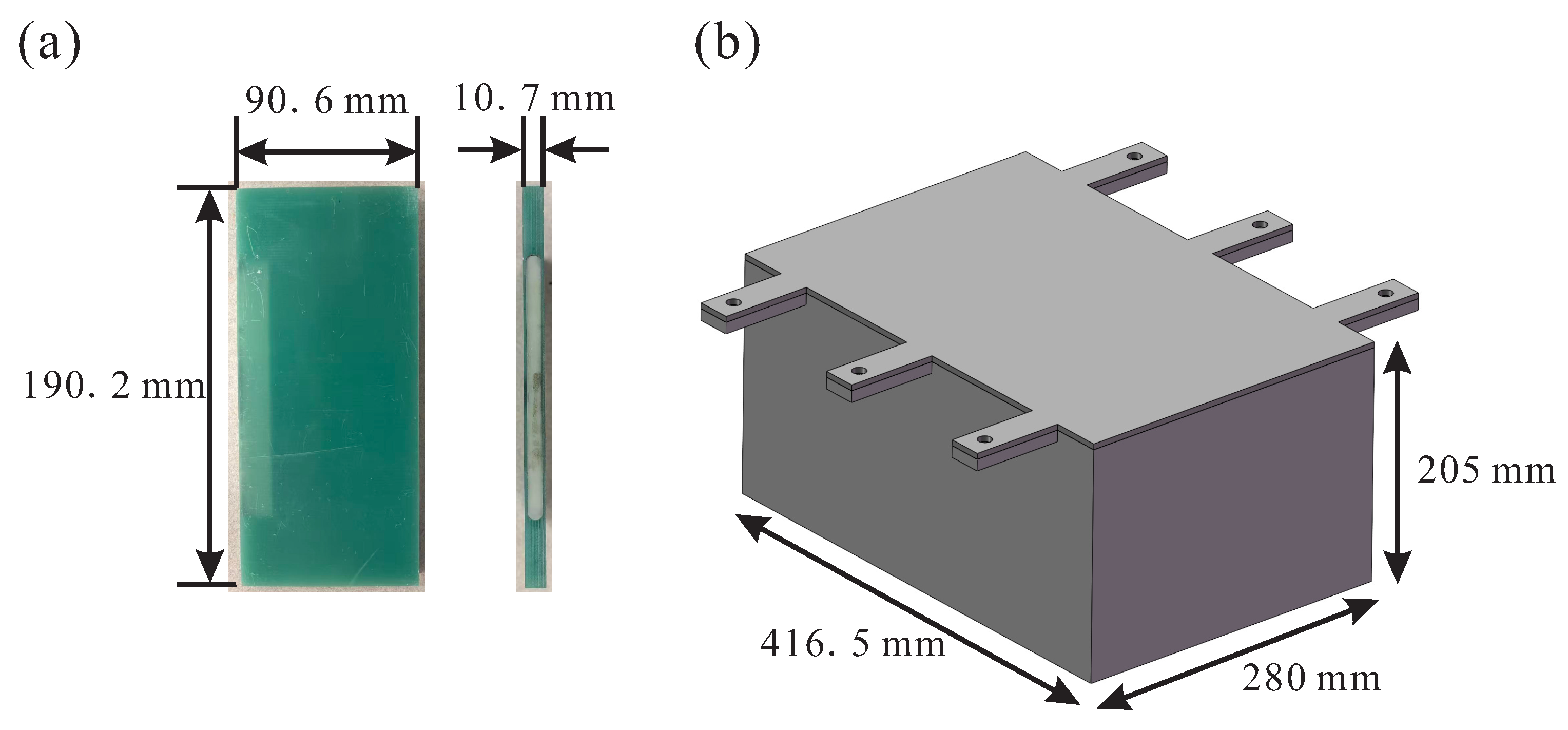
Figure 1.
(
a) Dimensions of the surrogate battery cell. (
b) Overall dimensions of the solid battery pack casing [
18].
Figure 1.
(
a) Dimensions of the surrogate battery cell. (
b) Overall dimensions of the solid battery pack casing [
18].
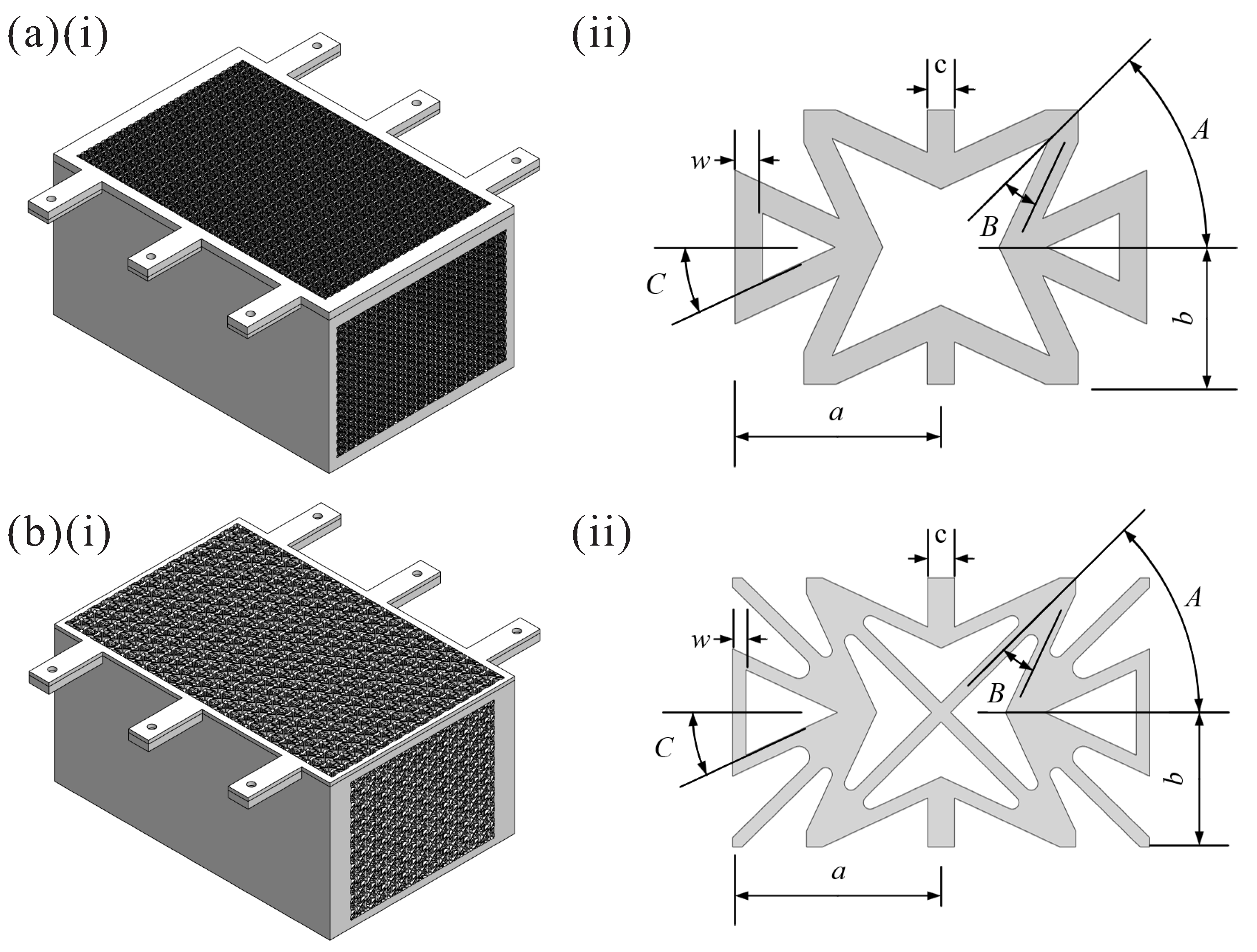
Figure 2.
Battery pack casings with (
a) STH [
11] and (
b) NHA [
19] wall modifications.
Figure 2.
Battery pack casings with (
a) STH [
11] and (
b) NHA [
19] wall modifications.
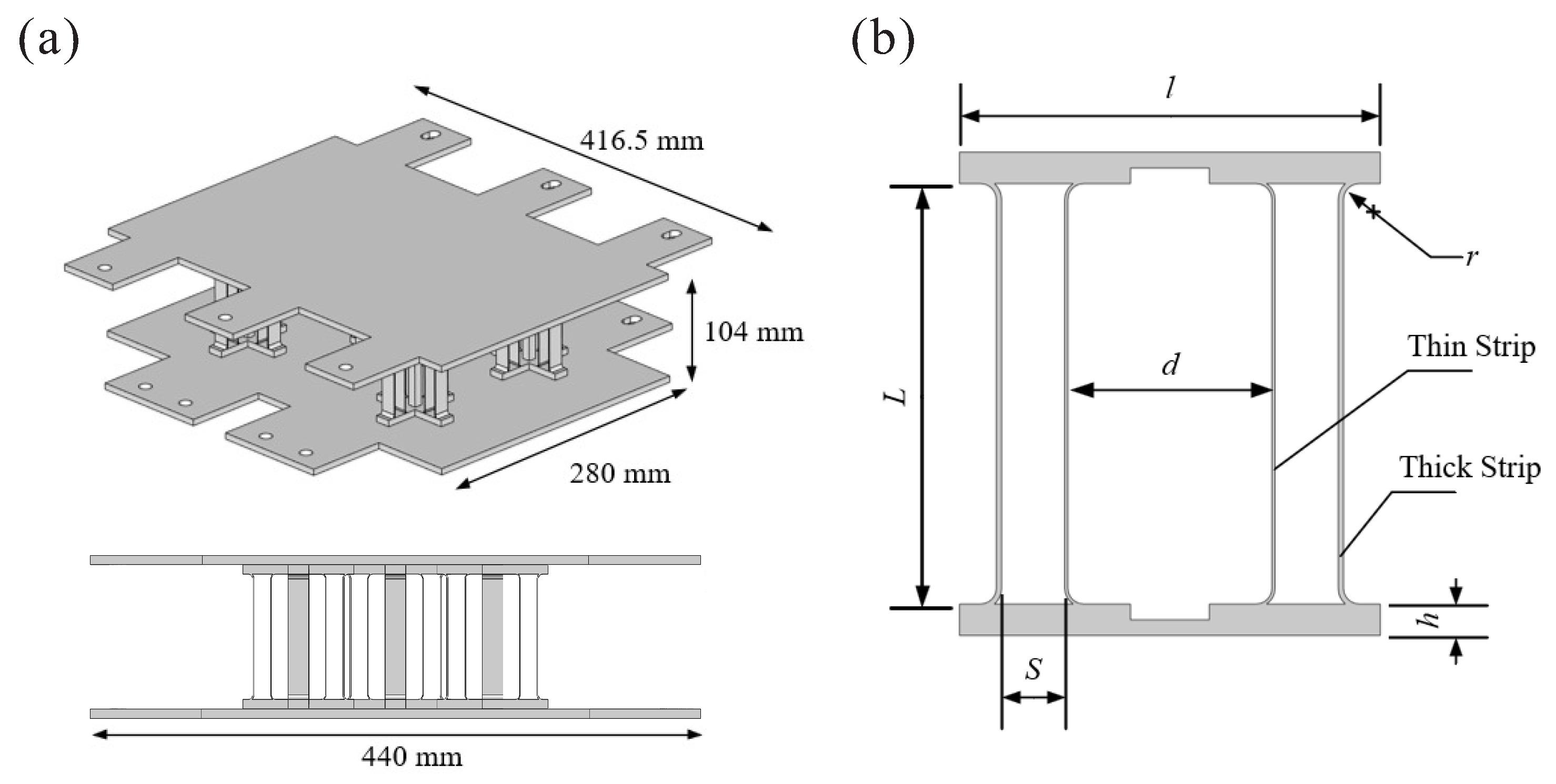
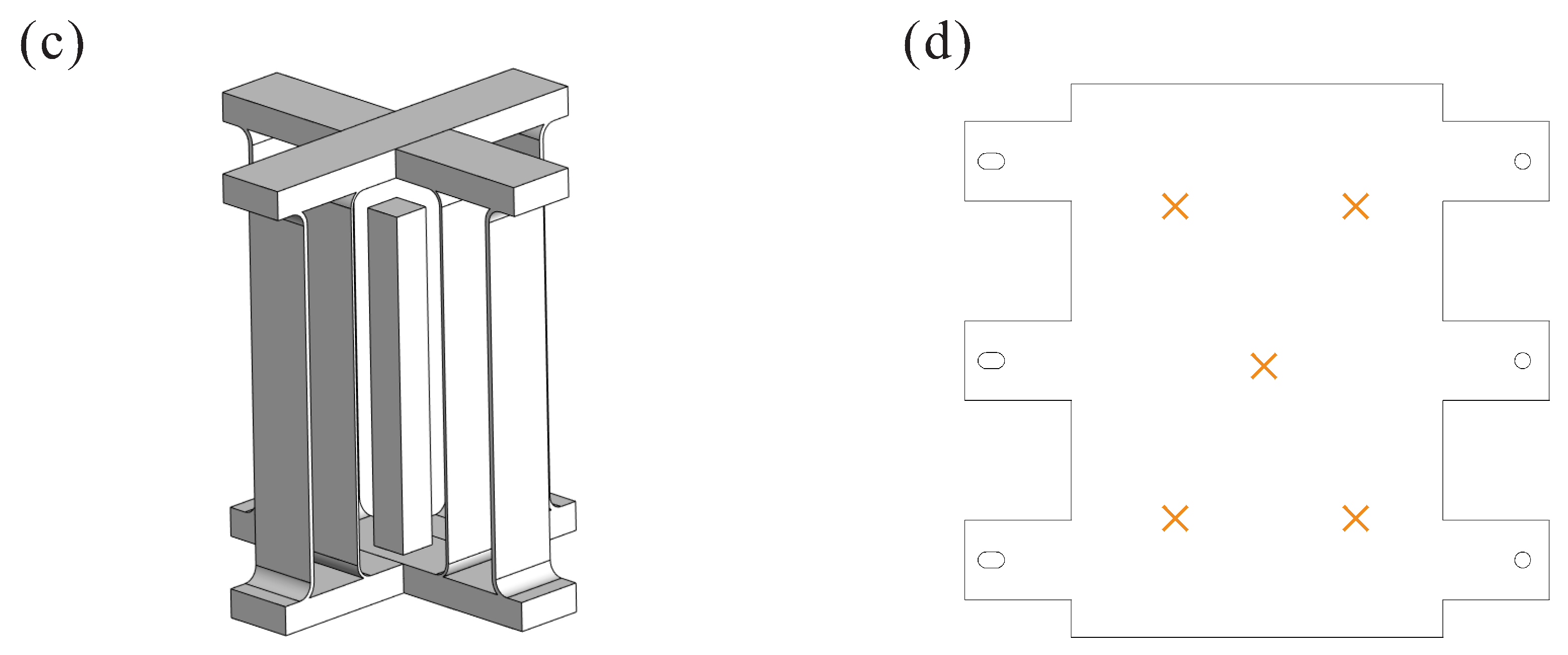
Figure 3.
(a) DSMS with its (b) unit cell and its (c) unit block. (d) The positions of five unit blocks.
Figure 3.
(a) DSMS with its (b) unit cell and its (c) unit block. (d) The positions of five unit blocks.
Figure 4.
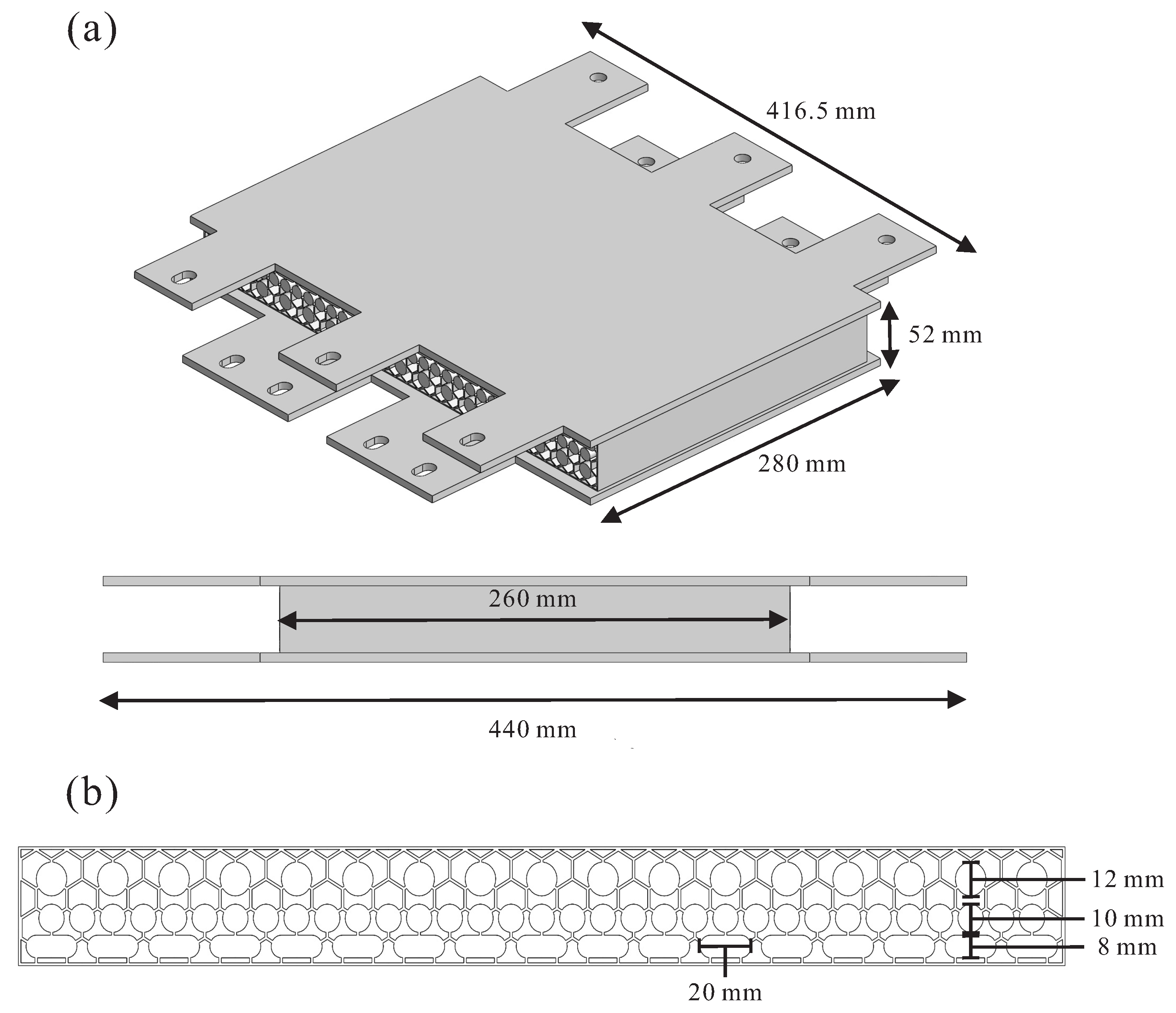
(a) BBIGPS with its (b) side view and dimensions of the cavities.
Figure 4.
(a) BBIGPS with its (b) side view and dimensions of the cavities.
Figure 5.
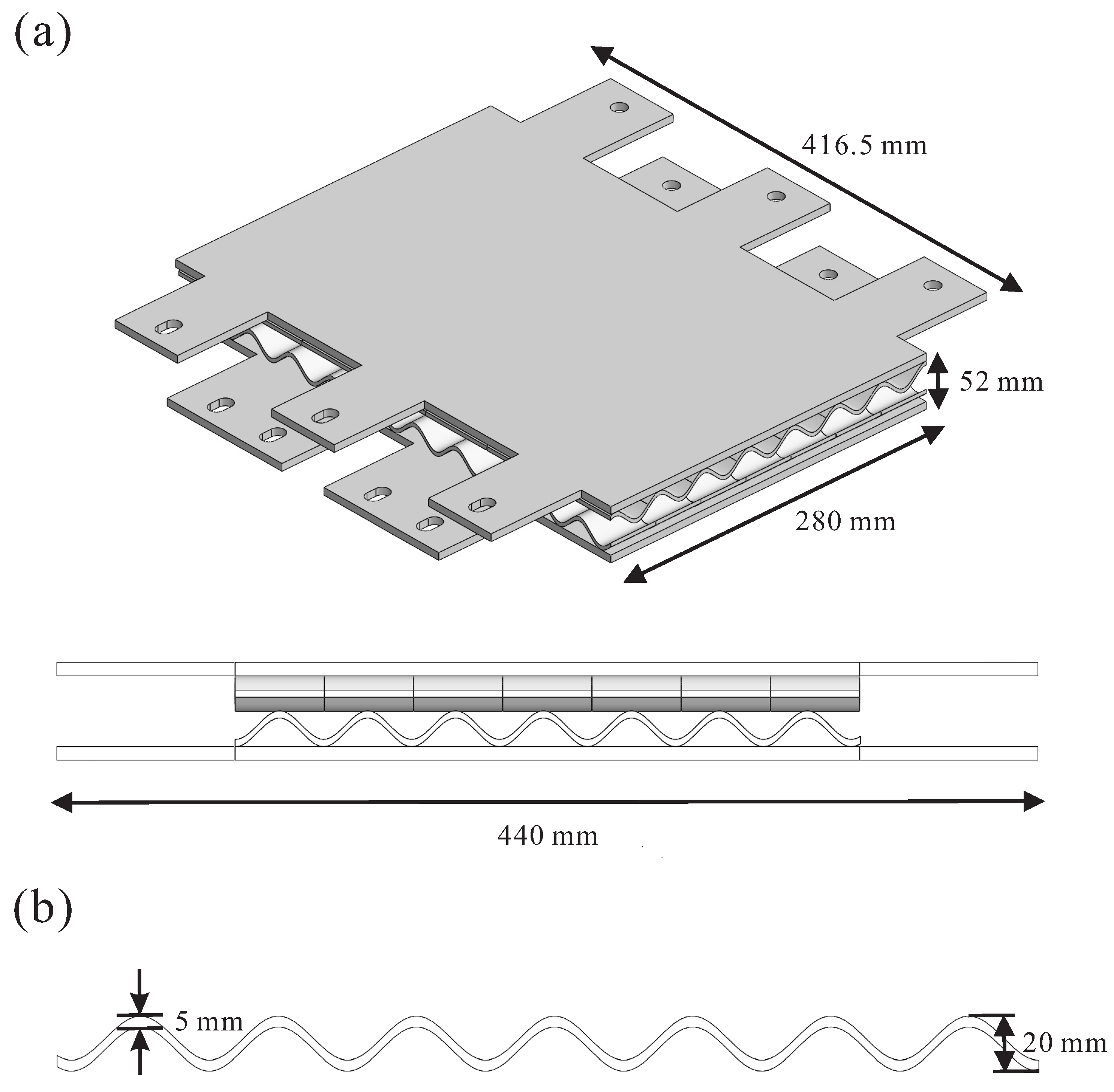
(a) BWBIS and its (b) unit cell dimensions.
Figure 5.
(a) BWBIS and its (b) unit cell dimensions.
Figure 6.
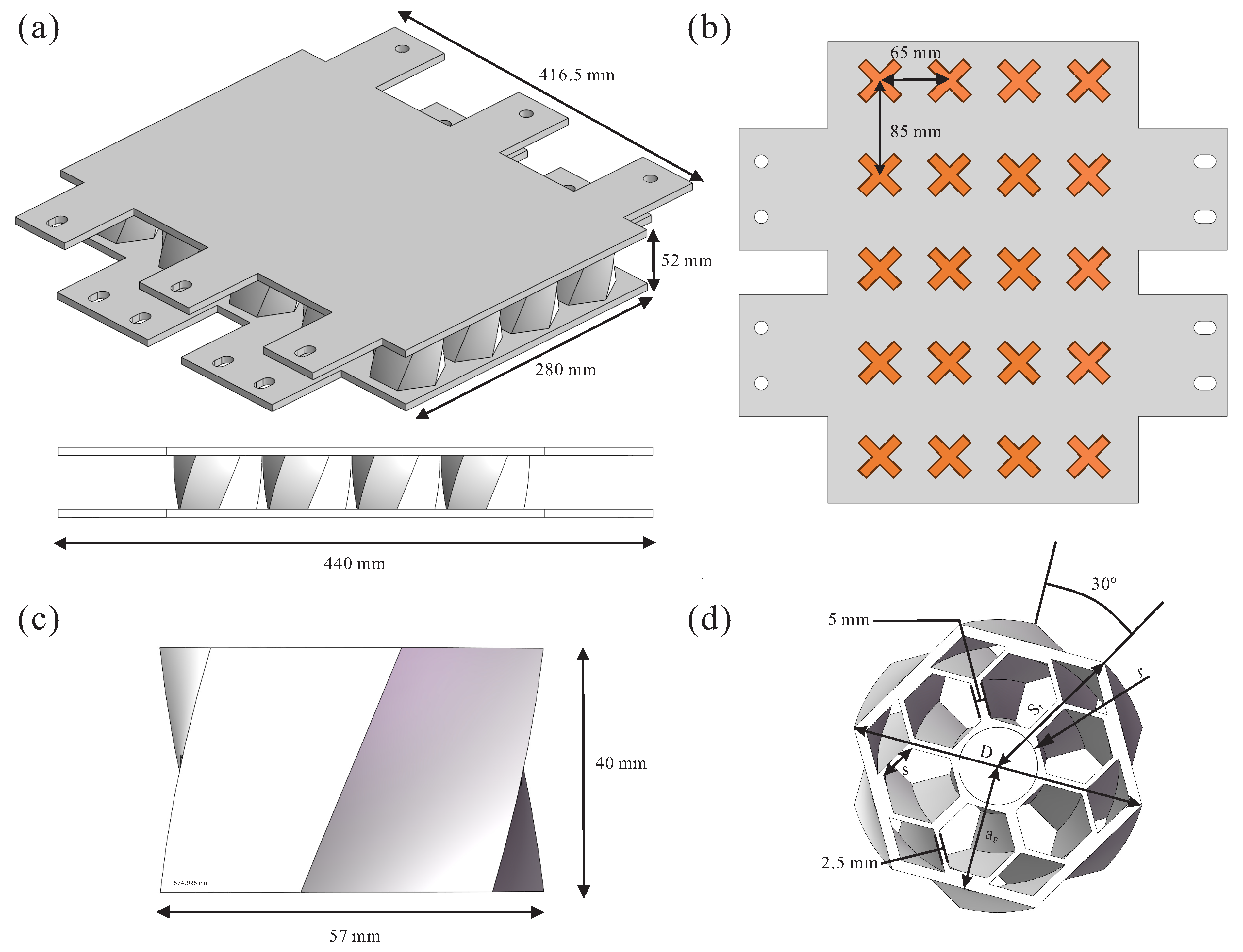
(a) BPPIS. (b) Arrangement of the BPPIS unit cells. (c) External dimensions of a unit cell. (d) Internal view showing wall thicknesses of 5 mm (center) and 2.5 mm (edge).
Figure 6.
(a) BPPIS. (b) Arrangement of the BPPIS unit cells. (c) External dimensions of a unit cell. (d) Internal view showing wall thicknesses of 5 mm (center) and 2.5 mm (edge).
Figure 7.
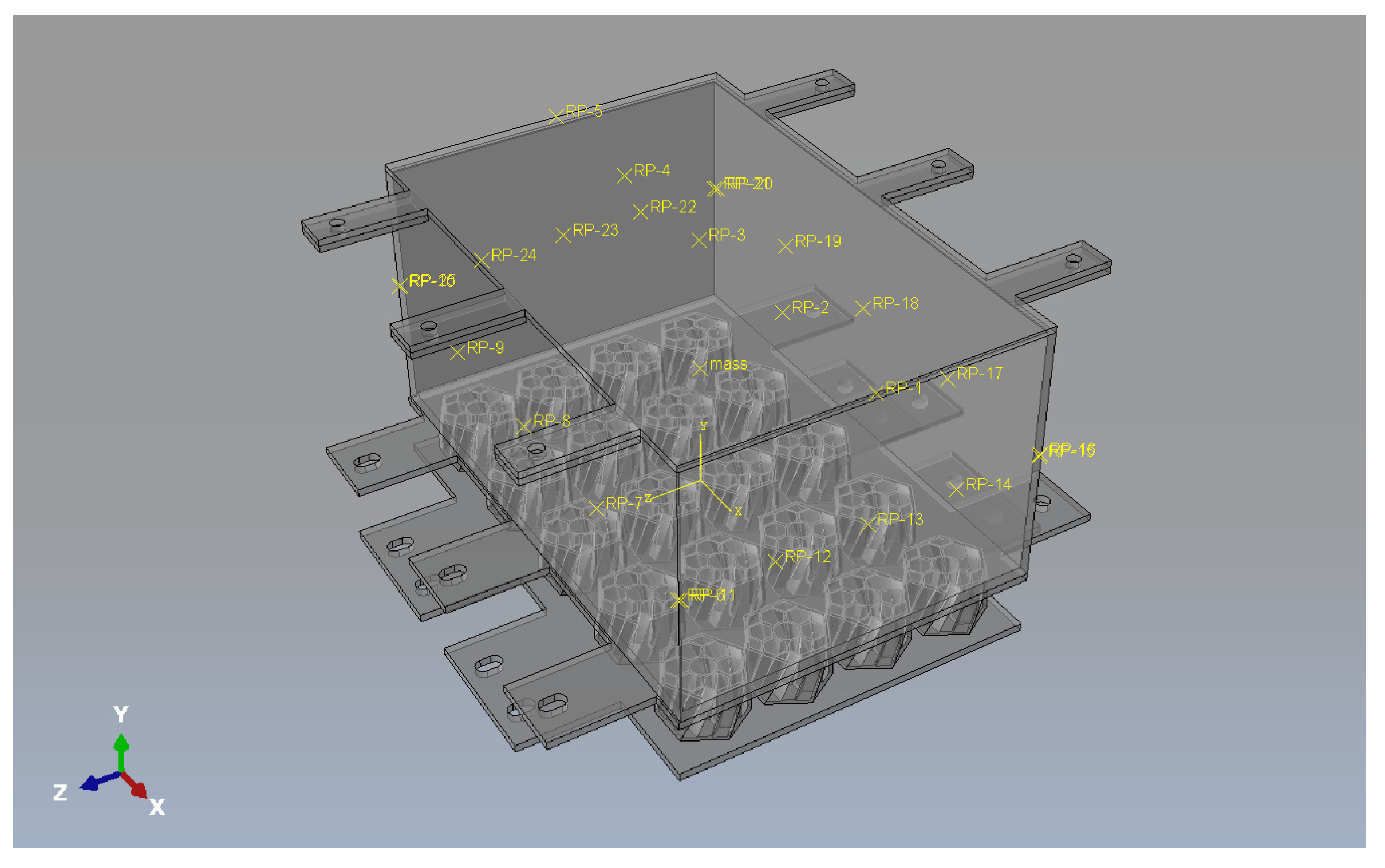
Numerical model of the present study. Only model with attached biomimetic pomelo peel structure is shown for brevity.
Figure 7.
Numerical model of the present study. Only model with attached biomimetic pomelo peel structure is shown for brevity.
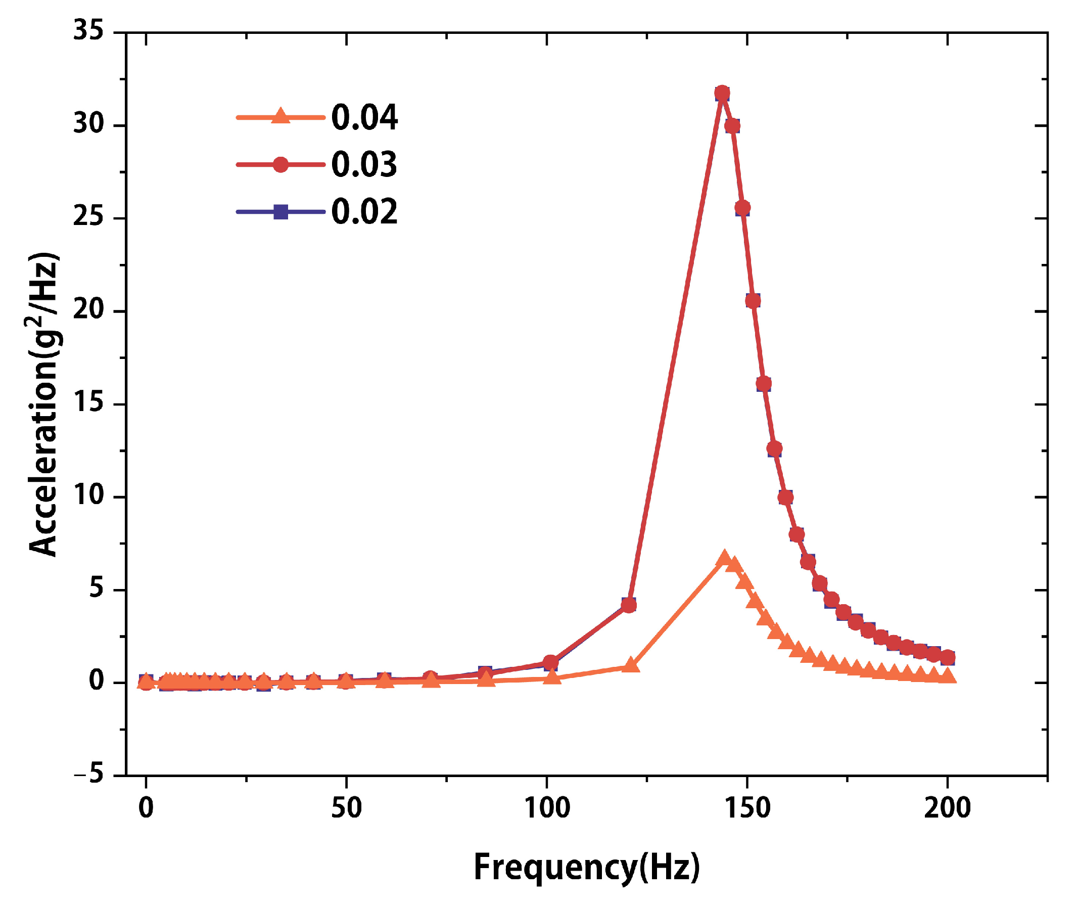
Figure 8.
Mesh convergence analysis of acceleration response under different global mesh sizes.
Figure 8.
Mesh convergence analysis of acceleration response under different global mesh sizes.
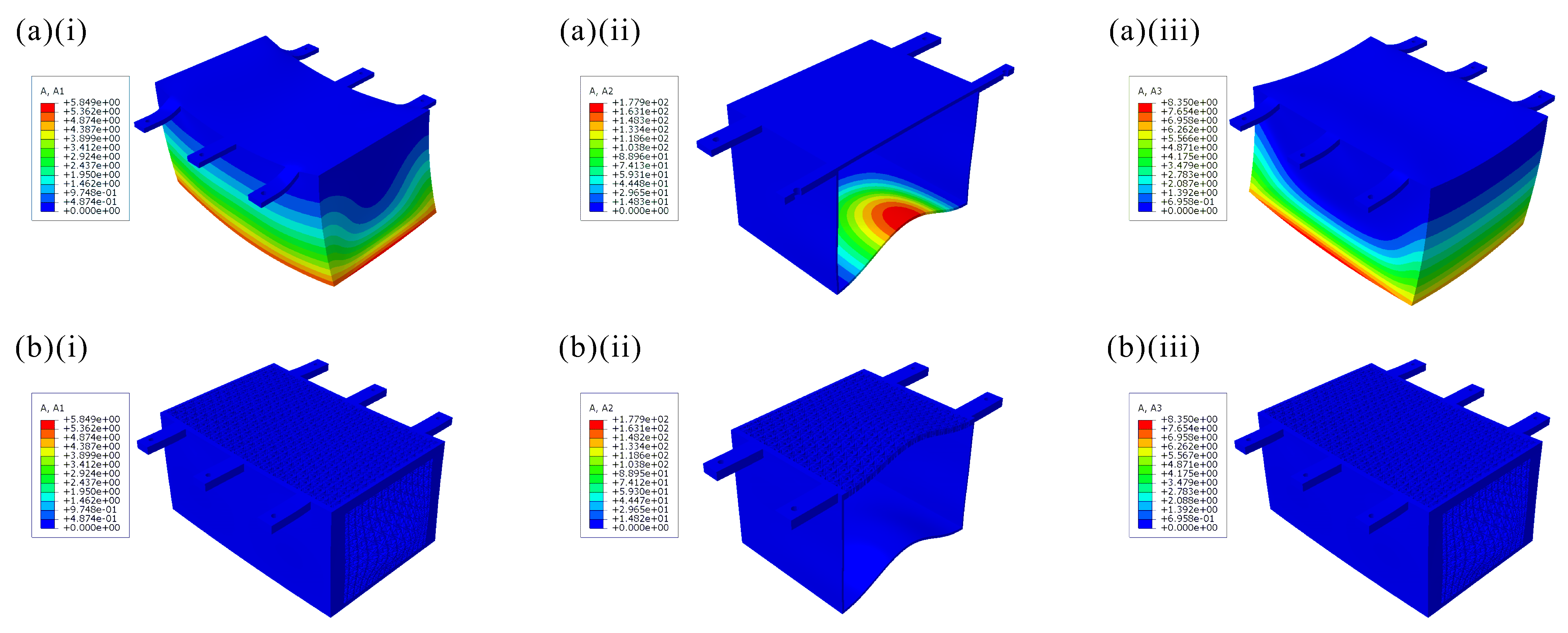
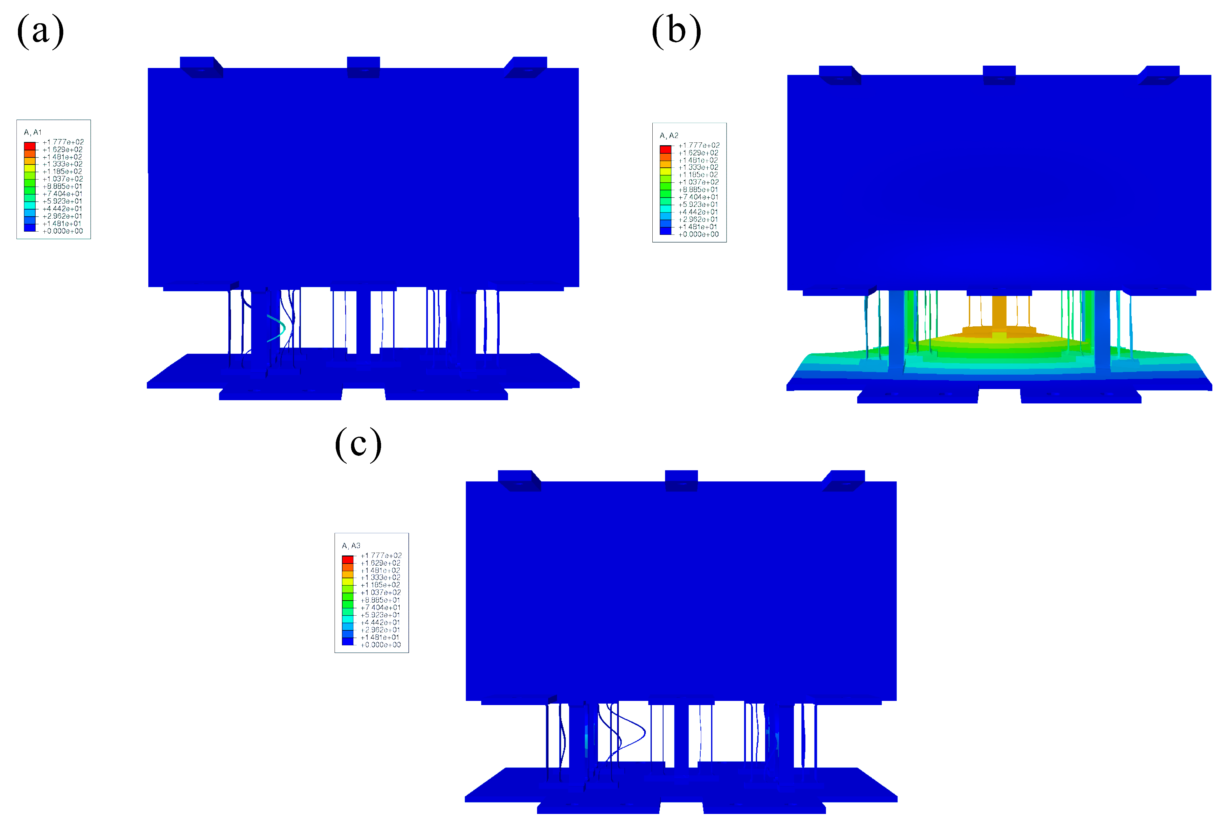
Figure 10.
Acceleration contours of the aluminum (a) solid, (b) NHA and (c) STH battery pack casings. ((i)–(iii)) represent longitudinal acceleration at 85 Hz, vertical acceleration at 45 Hz and transverse acceleration at 85 Hz, respectively.
Figure 10.
Acceleration contours of the aluminum (a) solid, (b) NHA and (c) STH battery pack casings. ((i)–(iii)) represent longitudinal acceleration at 85 Hz, vertical acceleration at 45 Hz and transverse acceleration at 85 Hz, respectively.
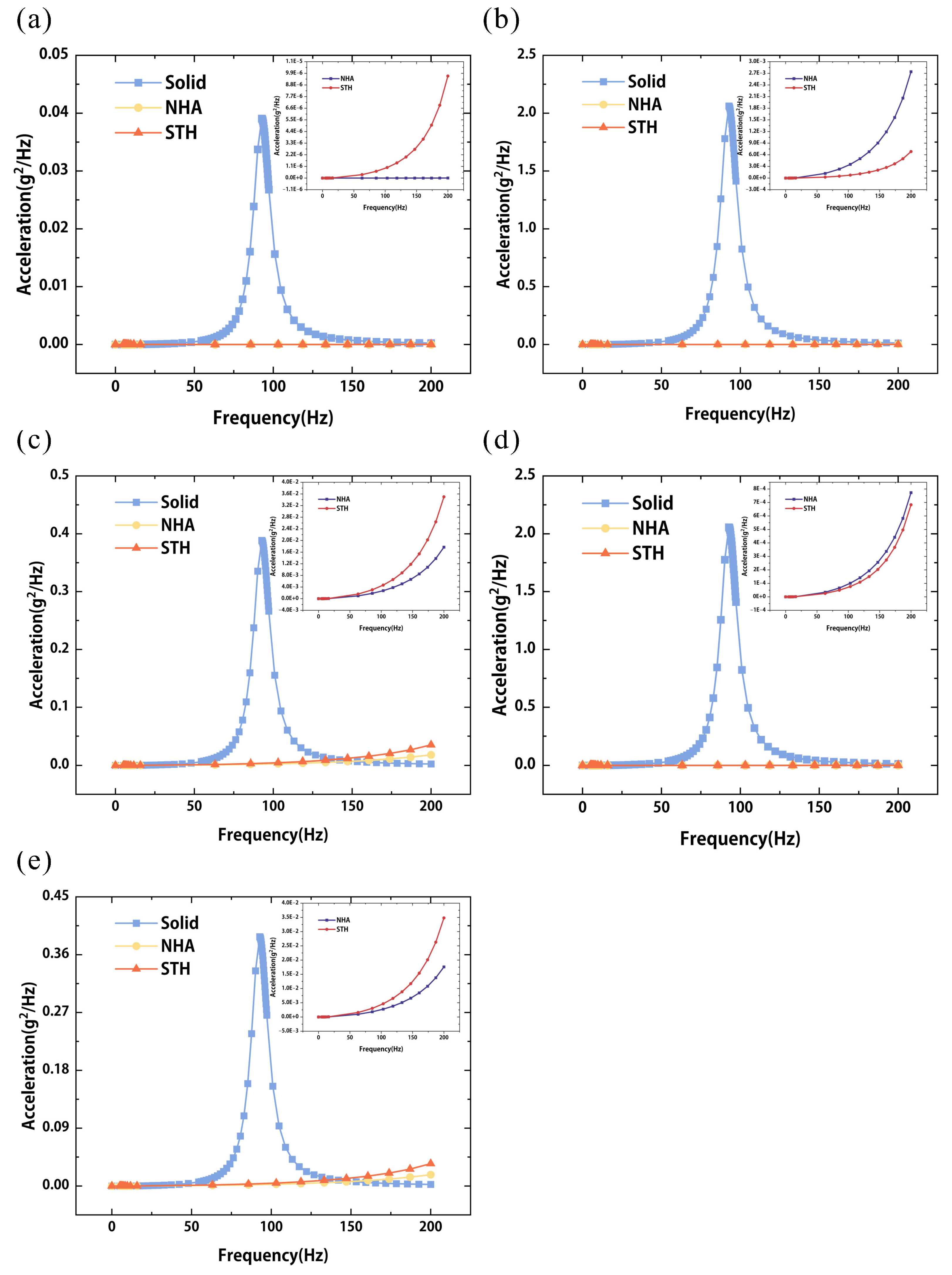
Figure 11.
Longitudinal acceleration of the three different aluminum battery pack casings at (a) RP3, (b) RP8, (c) RP13, (d) RP18, and (e) RP23.
Figure 11.
Longitudinal acceleration of the three different aluminum battery pack casings at (a) RP3, (b) RP8, (c) RP13, (d) RP18, and (e) RP23.
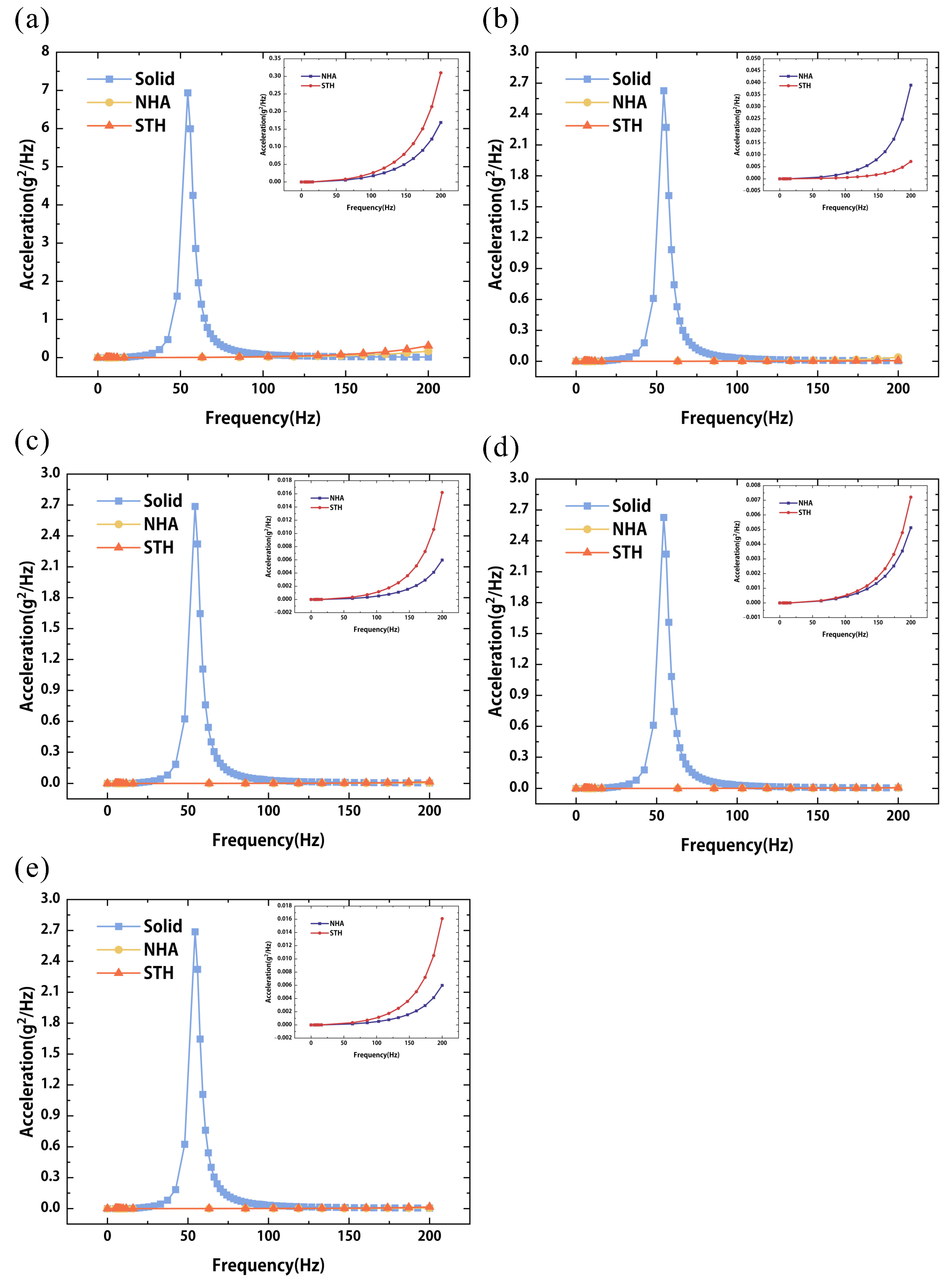
Figure 12.
Vertical acceleration of the three different aluminum battery pack casings at (a) RP3, (b) RP8, (c) RP13, (d) RP18, and (e) RP23.
Figure 12.
Vertical acceleration of the three different aluminum battery pack casings at (a) RP3, (b) RP8, (c) RP13, (d) RP18, and (e) RP23.
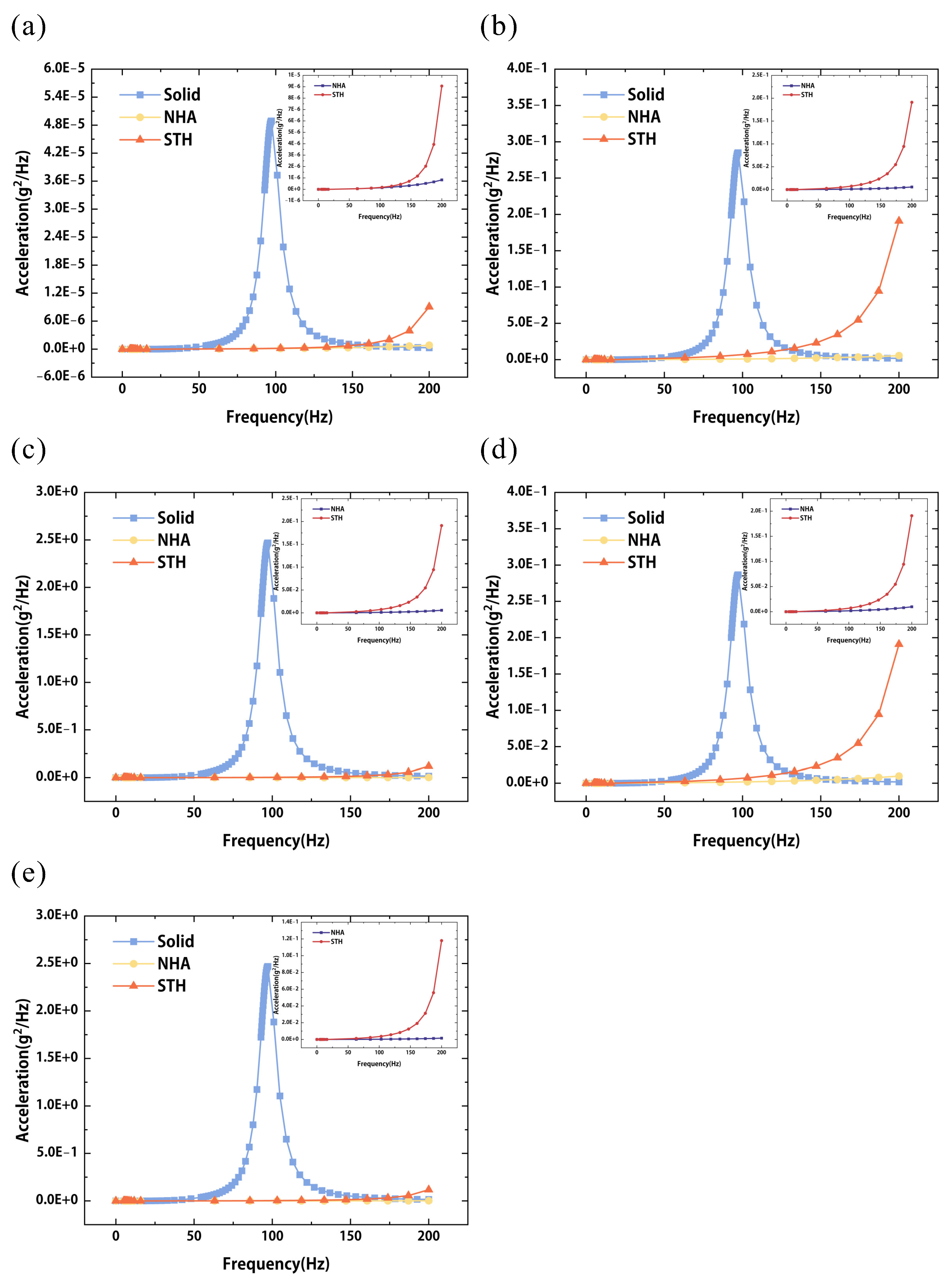
Figure 13.
Transverse acceleration of the three different aluminum battery pack casings at (a) RP3, (b) RP8, (c) RP13, (d) RP18, and (e) RP23.
Figure 13.
Transverse acceleration of the three different aluminum battery pack casings at (a) RP3, (b) RP8, (c) RP13, (d) RP18, and (e) RP23.
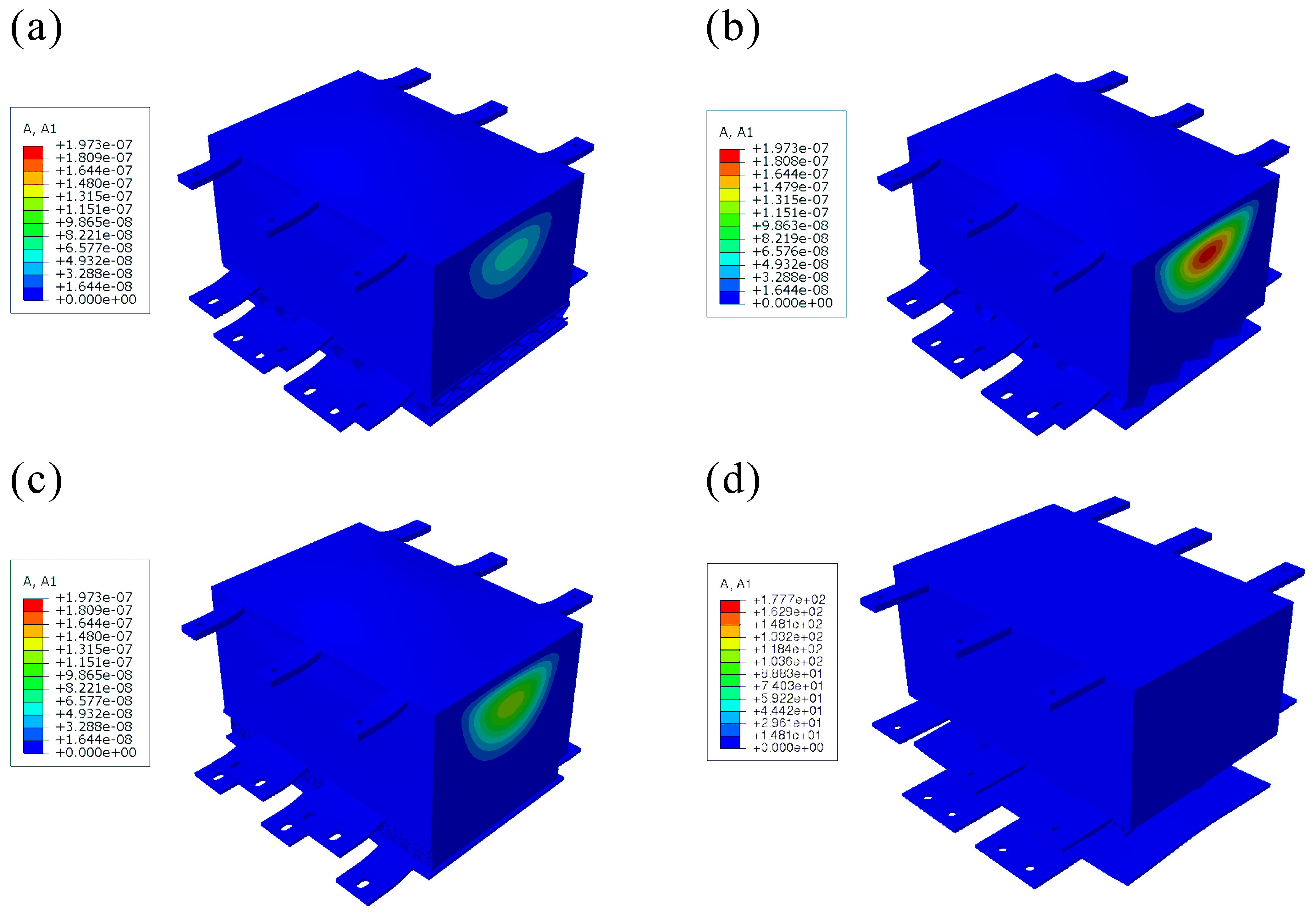
Figure 14.
Longitudinal acceleration contours (152 Hz) of the aluminum solid battery pack casing with different damping structures. (a) BWBIS (b) BPPIS (c) BBIGPS (d) DSMS.
Figure 14.
Longitudinal acceleration contours (152 Hz) of the aluminum solid battery pack casing with different damping structures. (a) BWBIS (b) BPPIS (c) BBIGPS (d) DSMS.
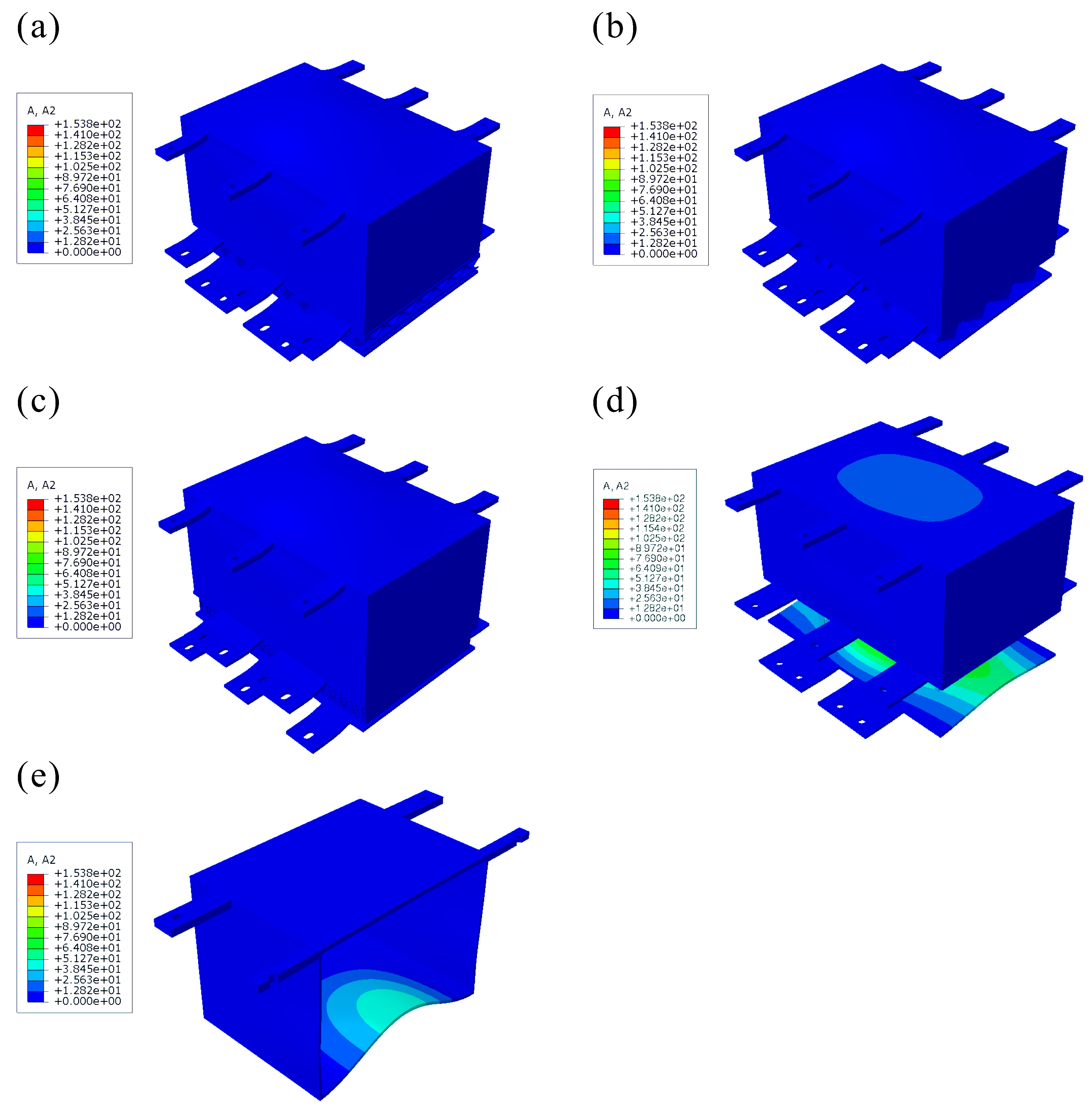
Figure 15.
Vertical acceleration contours (50 Hz) of the aluminum (e) solid battery pack casing with different damping structures. (a) BWBIS (b) BPPIS (c) BBIGPS (d) DSMS.
Figure 15.
Vertical acceleration contours (50 Hz) of the aluminum (e) solid battery pack casing with different damping structures. (a) BWBIS (b) BPPIS (c) BBIGPS (d) DSMS.
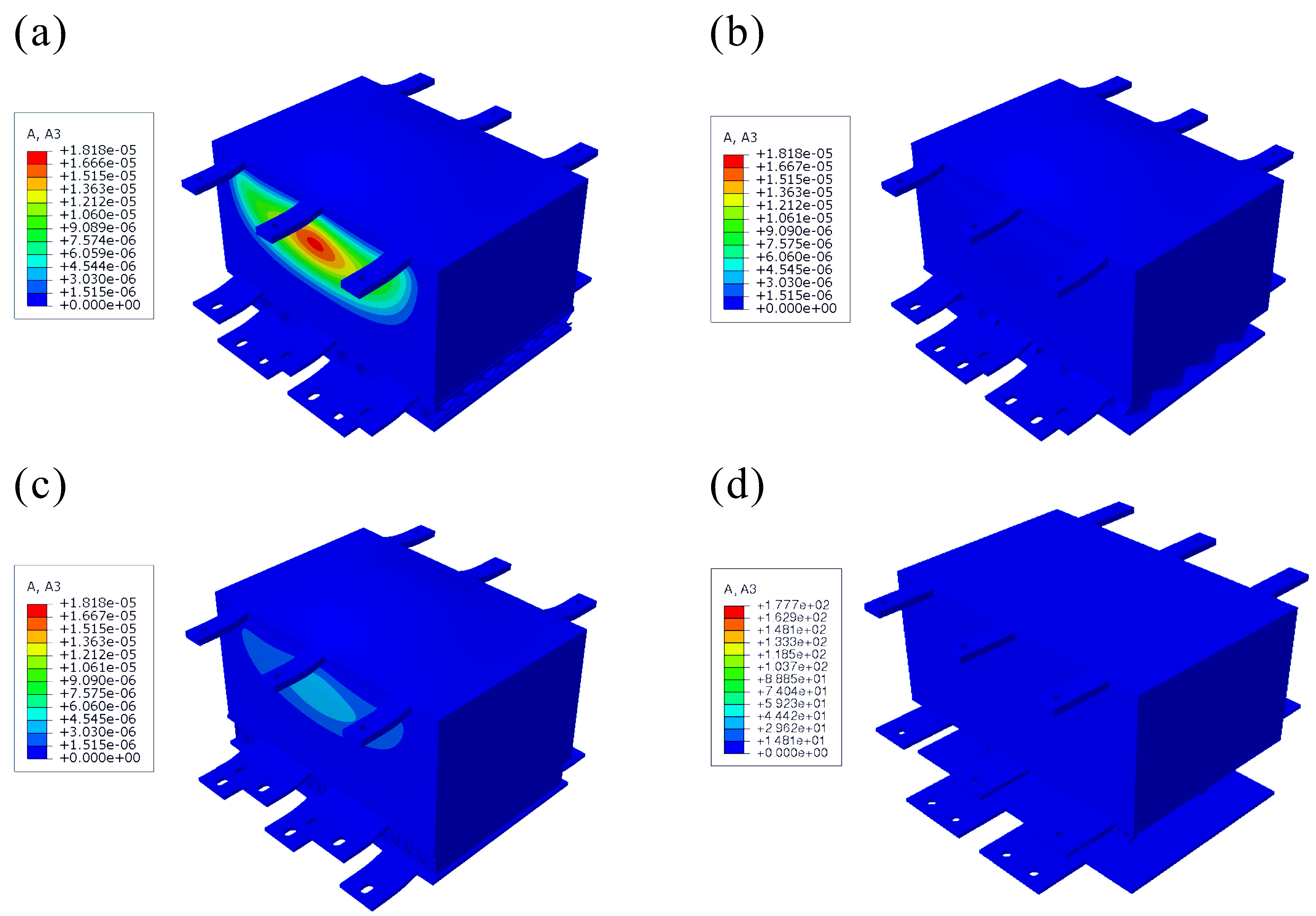
Figure 16.
Transverse acceleration contours (160 Hz) of the aluminum solid battery pack casing with different damping structures. (a) BWBIS (b) BPPIS (c) BBIGPS (d) DSMS.
Figure 16.
Transverse acceleration contours (160 Hz) of the aluminum solid battery pack casing with different damping structures. (a) BWBIS (b) BPPIS (c) BBIGPS (d) DSMS.
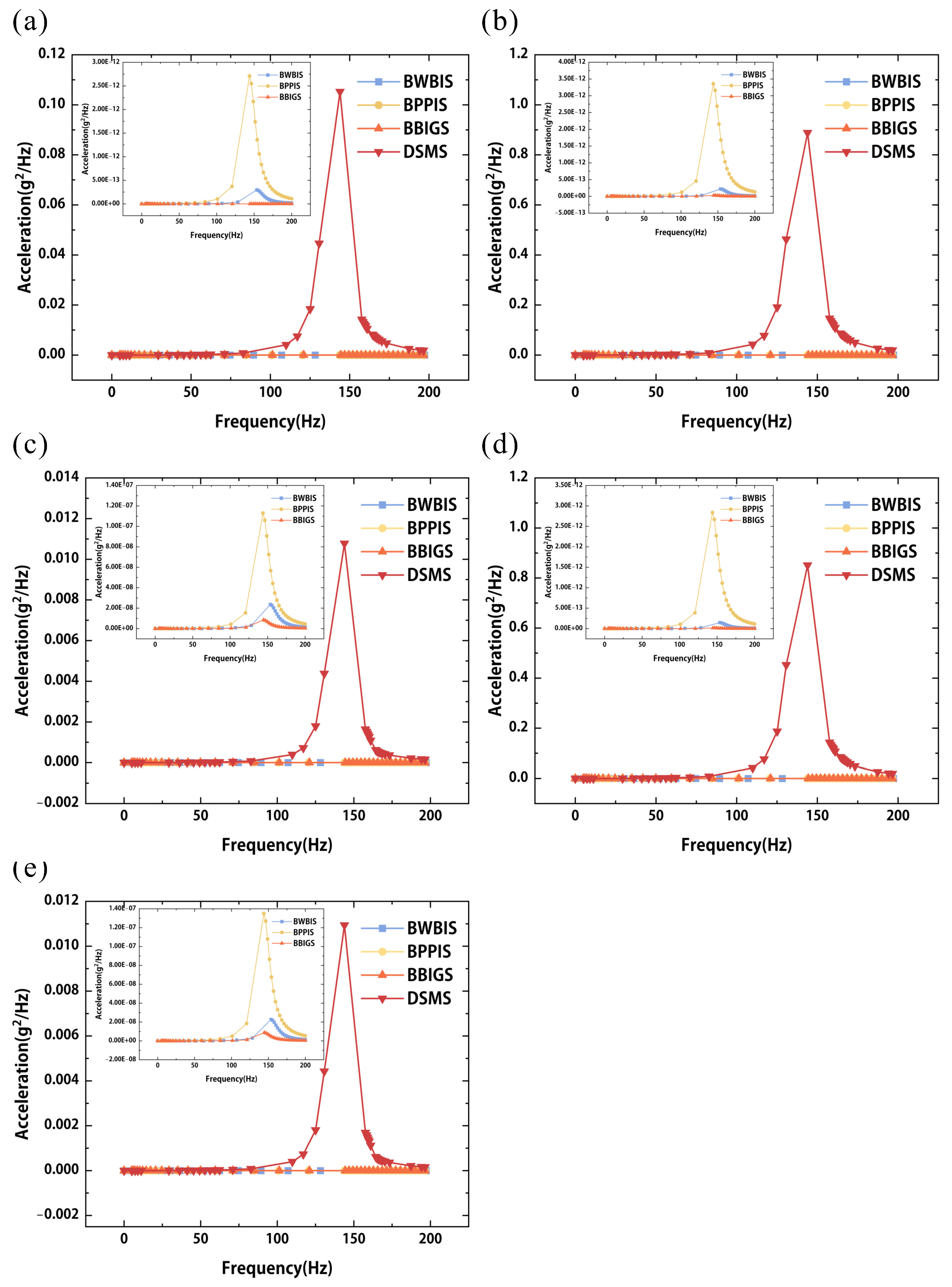
Figure 17.
Longitudinal acceleration of the aluminum solid battery pack casing with different damping structures at (a) RP3, (b) RP8, (c) RP13, (d) RP18, and (e) RP23.
Figure 17.
Longitudinal acceleration of the aluminum solid battery pack casing with different damping structures at (a) RP3, (b) RP8, (c) RP13, (d) RP18, and (e) RP23.
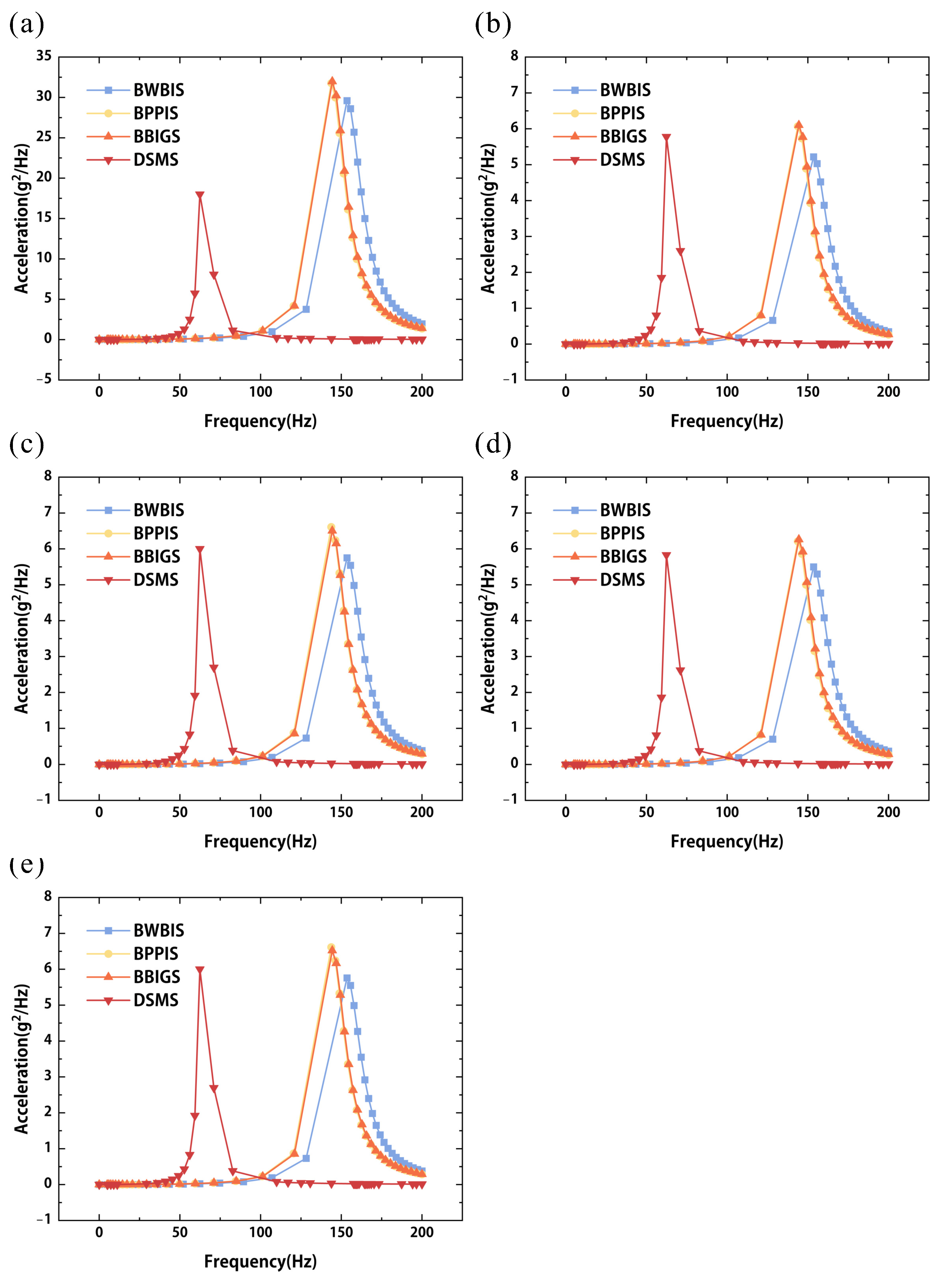
Figure 18.
Vertical acceleration of the aluminum solid battery pack casing different damping structures at (a) RP3, (b) RP8, (c) RP13, (d) RP18, and (e) RP23.
Figure 18.
Vertical acceleration of the aluminum solid battery pack casing different damping structures at (a) RP3, (b) RP8, (c) RP13, (d) RP18, and (e) RP23.
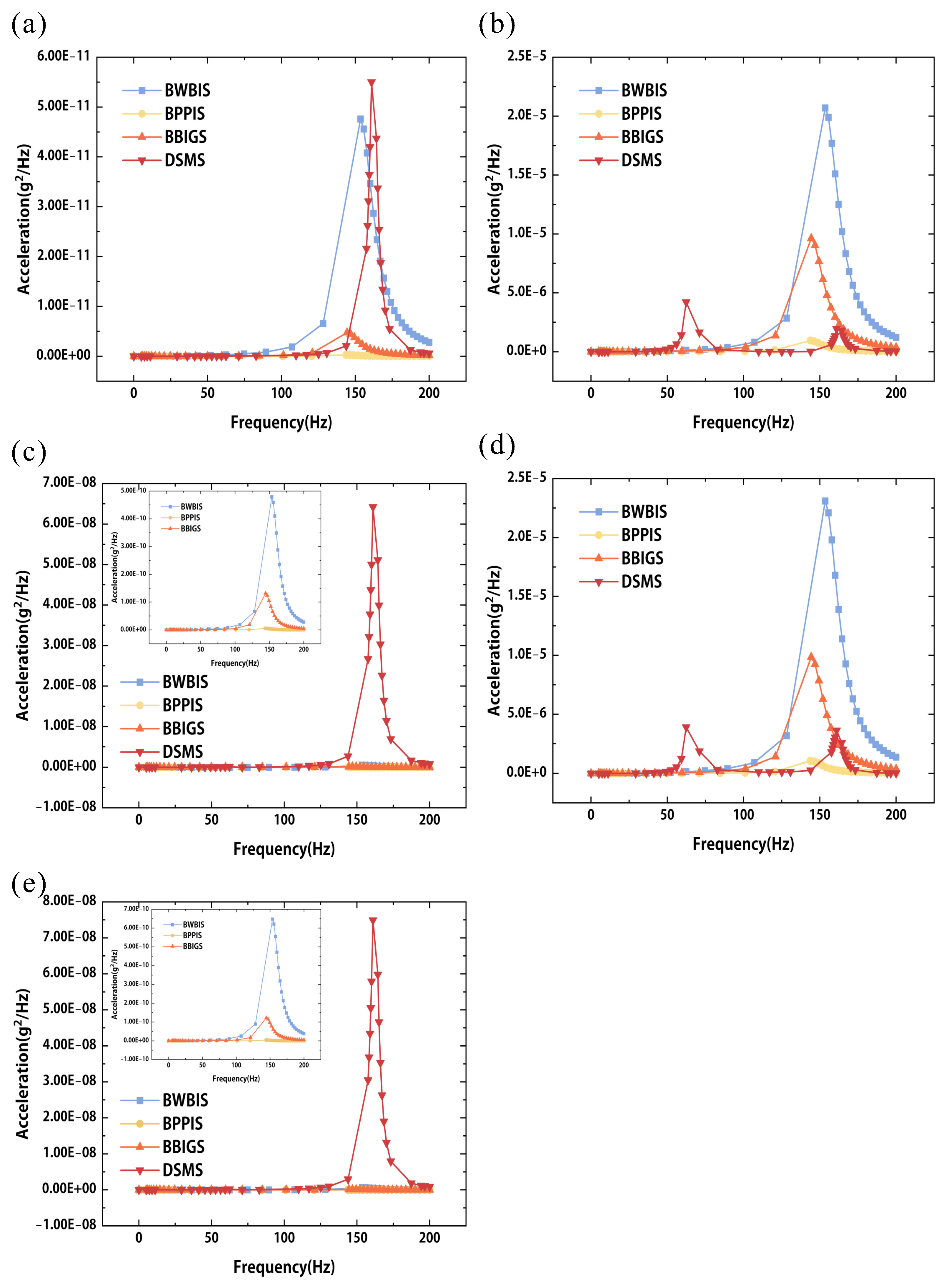
Figure 19.
Transverse acceleration of the aluminum solid battery pack casing with different damping structures at (a) RP3, (b) RP8, (c) RP13, (d) RP18, and (e) RP23.
Figure 19.
Transverse acceleration of the aluminum solid battery pack casing with different damping structures at (a) RP3, (b) RP8, (c) RP13, (d) RP18, and (e) RP23.
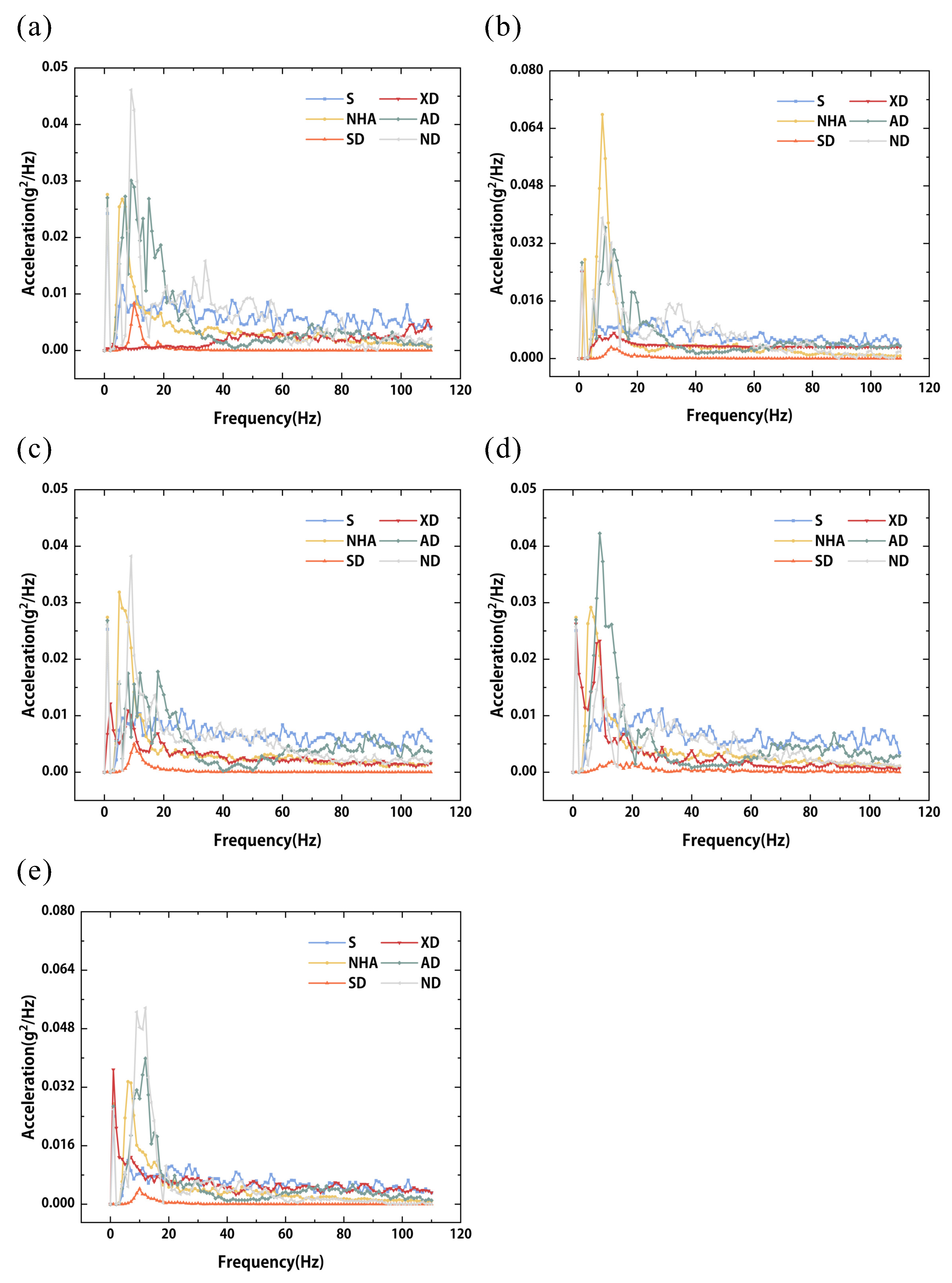
Figure 20.
Longitudinal acceleration of the modified battery pack casings with BPPIS at (a) RP11, (b) RP12, (c) RP13, (d) RP14, and (e) RP15. S: solid, SD: solid with BPPIS, XD: X-shaped with BPPIS, AD: auxetic with BPPIS, ND: NHA with BPPIS.
Figure 20.
Longitudinal acceleration of the modified battery pack casings with BPPIS at (a) RP11, (b) RP12, (c) RP13, (d) RP14, and (e) RP15. S: solid, SD: solid with BPPIS, XD: X-shaped with BPPIS, AD: auxetic with BPPIS, ND: NHA with BPPIS.
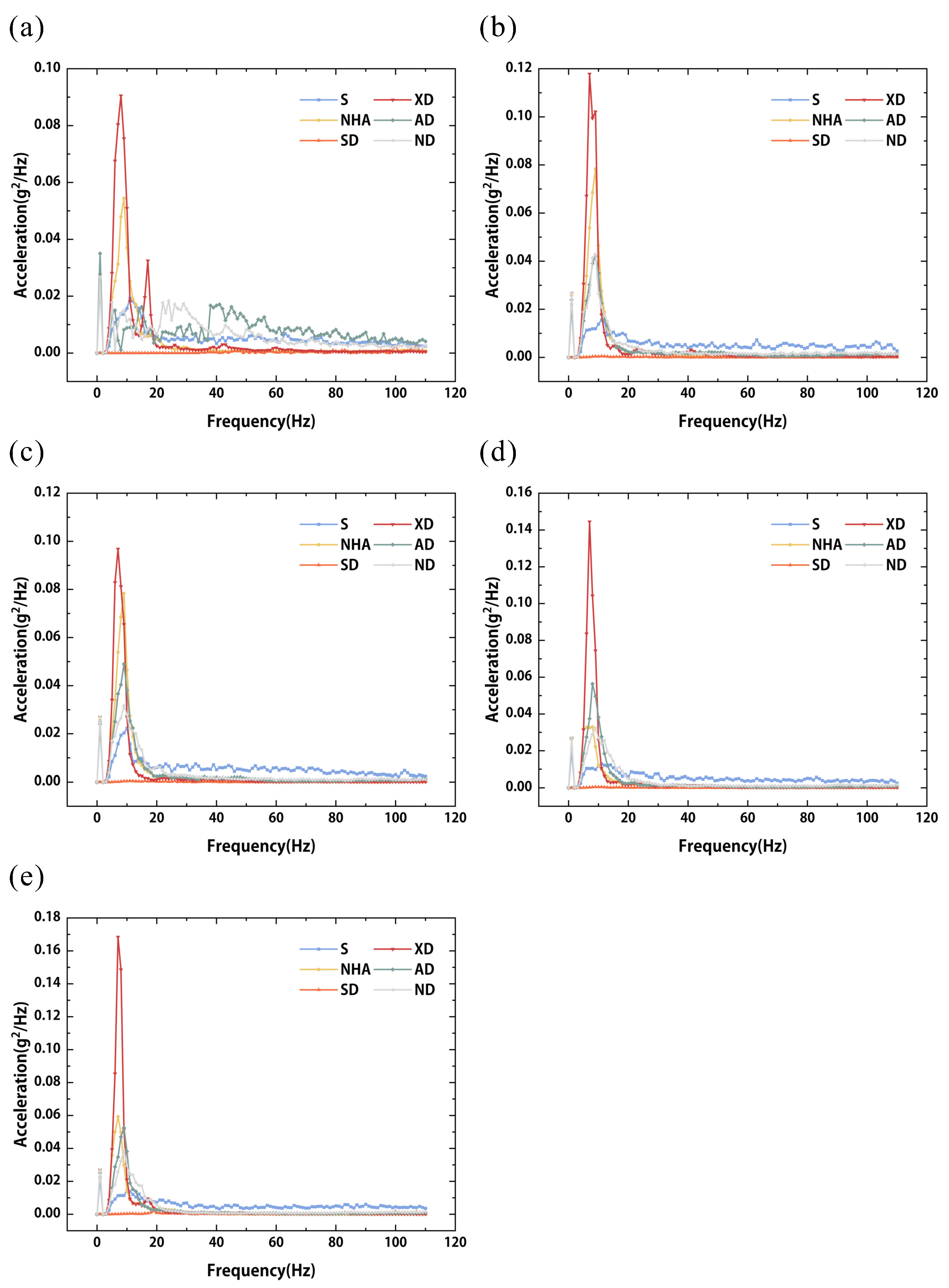
Figure 21.
Vertical acceleration of the modified battery pack casings with BPPIS at (a) RP1, (b) RP2, (c) RP3, (d) RP4, and (e) RP5.
Figure 21.
Vertical acceleration of the modified battery pack casings with BPPIS at (a) RP1, (b) RP2, (c) RP3, (d) RP4, and (e) RP5.
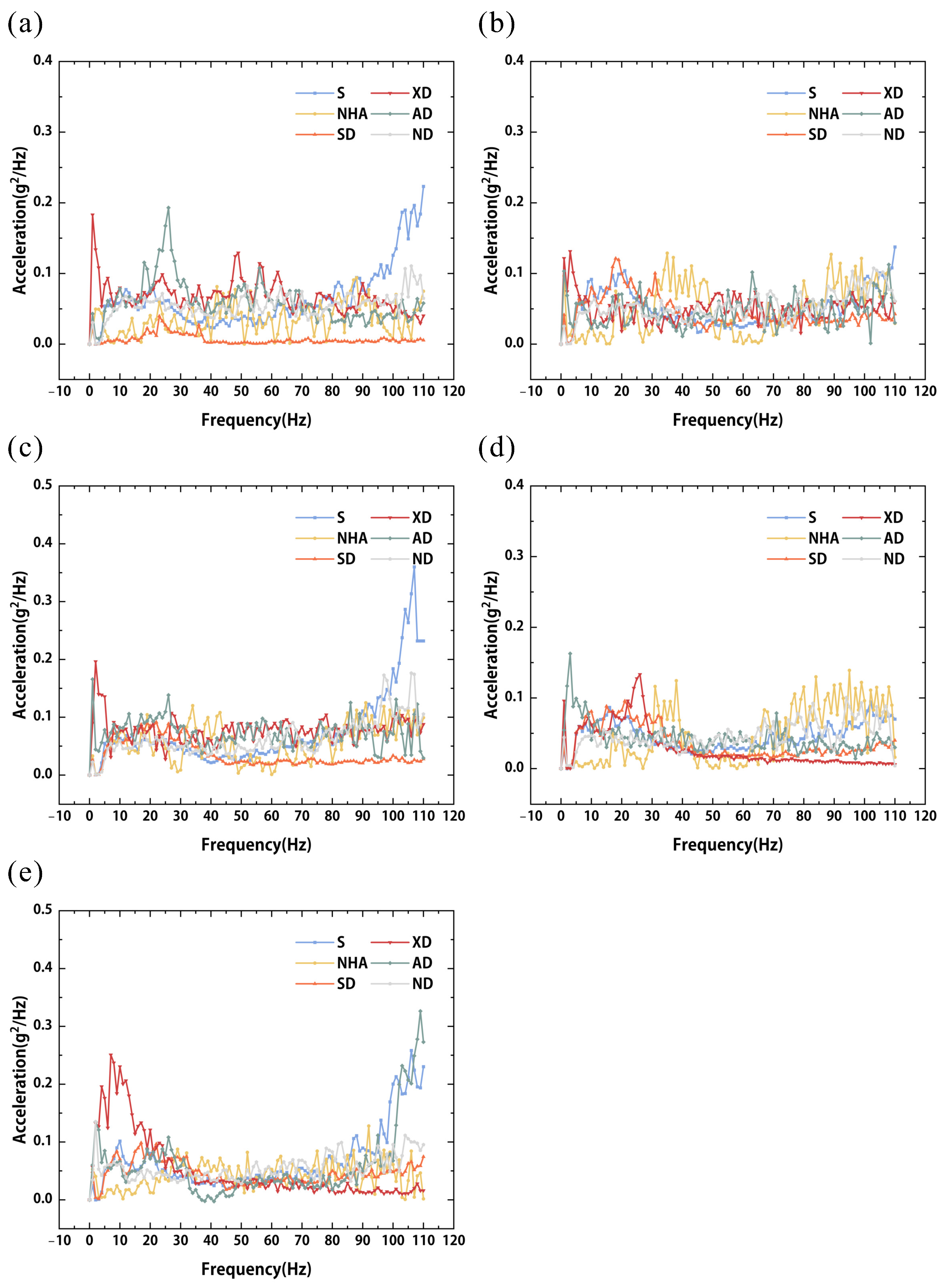
Figure 22.
Transverse acceleration of the modified battery pack casings with BPPIS at (a) RP6, (b) RP7, (c) RP8, (d) RP9, and (e) RP10.
Figure 22.
Transverse acceleration of the modified battery pack casings with BPPIS at (a) RP6, (b) RP7, (c) RP8, (d) RP9, and (e) RP10.
Table 1.
The dimensions of STH and NHA unit cells.
Table 1.
The dimensions of STH and NHA unit cells.
| Structures
| Dimensions |
|---|
| | | | | | |
|---|
| STH | 7.5 | 5 | 2 | 1 | | | |
| NHA | 15.5 | 10 | 2 | 1 | | | |
| Notes: The values of a, b, c and w are all in millimeters. |
Table 2.
Material properties of AlSi10Mg (as-printed) [
33].
Table 2.
Material properties of AlSi10Mg (as-printed) [
33].
| Materials | Properties | Unit | Value |
|---|
| AlSi10Mg | Density () | kg/m3 | 2700 |
| Poisson ratio () | – | 0.3 |
| Tensile strength () | MPa | 330 |
| Yield strength () | MPa | 210 |
| Hardness | HRC | 75 |
| Elongation at break (A) | – | 11% |
| Young’s modulus as-printed (E) | GPa | 44 |
Table 3.
The weights of all structures that have been used in the shock and vibration experiments.
Table 3.
The weights of all structures that have been used in the shock and vibration experiments.
| Structures | Weight (g) |
|---|
| Aluminum solid battery pack casing | 6250.0 |
| Aluminum auxetic battery pack casing | 5214.0 |
| Aluminum X-shaped battery pack casing | 4616.0 |
| Aluminum NHA battery pack casing | 4616.0 |
| Aluminum BPPIS | 4760.0 |
| Surrogate battery cell | 386.0 |
Table 4.
Vibration mitigation capabilities of the aluminum NHA and STH battery pack casings in three directions.
Table 4.
Vibration mitigation capabilities of the aluminum NHA and STH battery pack casings in three directions.
| Modified Battery Pack Casing | Longitudinal (%) | Vertical (%) | Transverse (%) |
|---|
| NHA | 98.07 | 95.09 | 93.60 |
| STH | 97.64 | 94.00 | 91.51 |
Table 5.
Vibration mitigation capabilities of the aluminum solid battery pack casing with different damping structures in three directions.
Table 5.
Vibration mitigation capabilities of the aluminum solid battery pack casing with different damping structures in three directions.
| Damping Structure | Longitudinal (%) | Vertical (%) | Transverse (%) |
|---|
| BPPIS | 99.99 | −92.84 | 99.78 |
| BWBIS | 99.98 | −88.48 | 99.96 |
| BBIGPS | 99.99 | −89.29 | 99.87 |
| DSMS | 74.46 | −2.46 | 99.89 |
Table 6.
The shock damping capability of the modified casings and damping structures in three directions.
Table 6.
The shock damping capability of the modified casings and damping structures in three directions.
| Direction | Point | NHA (%) | NHA-BPPIS (%) | Auxetic (%) | Auxetic-BPPIS (%) |
|---|
| Vertical | RP 1 | −86.41 | −96.45 | 3.33 | −109.55 |
| RP 2 | −126.58 | −149.44 | −10.92 | −136.49 |
| RP 3 | −61.47 | −66.61 | 19.95 | −77.15 |
| RP 4 | −62.37 | −62.12 | 8.96 | −88.51 |
| RP 5 | −104.35 | −50.62 | −7.34 | −146.17 |
| Longitudinal | RP 11 | 16.03 | 85.47 | 21.40 | 84.83 |
| RP 12 | 12.43 | 75.83 | −199.02 | 84.54 |
| RP 13 | 32.28 | 76.39 | −56.50 | 81.19 |
| RP 14 | −47.61 | 55.25 | −269.77 | 71.68 |
| RP 15 | 45.35 | 74.79 | −5.71 | 81.71 |
| RP 21 | 5.72 | 59.71 | 17.96 | 74.79 |
| RP 22 | −38.35 | 50.21 | −75.14 | 54.75 |
| RP 23 | −13.76 | 32.53 | −56.95 | 27.38 |
| RP 24 | −44.49 | −71.67 | −124.44 | −28.64 |
| RP 25 | 50.55 | 72.23 | 1.91 | 76.77 |
| Transverse | RP 6 | 7.30 | 82.64 | −1.62 | 86.17 |
| RP 7 | 25.48 | 22.95 | 3.29 | 90.18 |
| RP 8 | 26.60 | 35.09 | 8.82 | 87.64 |
| RP 9 | 20.51 | 68.74 | 19.56 | 84.59 |
| RP 10 | −16.08 | 81.82 | 37.80 | 84.65 |
| RP 16 | −9.62 | 82.15 | 5.00 | 87.02 |
| RP 17 | −18.87 | 65.52 | 6.27 | 96.01 |
| RP 18 | 5.89 | 59.35 | 42.17 | 95.32 |
| RP 19 | 61.47 | 85.87 | 33.58 | 95.45 |
| RP 20 | 10.04 | 84.08 | −2.88 | 88.20 |
Table 7.
The longitudinal vibration damping capability of the modified battery pack casings and damping structures in three directions.
Table 7.
The longitudinal vibration damping capability of the modified battery pack casings and damping structures in three directions.
| Direction | Point | NHA (%) | Solid-BPPIS (%) | X-Shaped-BPPIS (%) | Auxetic-BPPIS (%) | NHA-BPPIS (%) |
|---|
| Longitudinal | RP 11 | 21.66 | 90.15 | 43.91 | 8.20 | 1.09 |
| RP 12 | 10.98 | 88.58 | 24.94 | 3.44 | −1.72 |
| RP 13 | 24.58 | 90.12 | 36.67 | 15.55 | 10.19 |
| RP 14 | 22.02 | 81.07 | 35.97 | 8.87 | 17.44 |
| RP 15 | 15.86 | 90.75 | 7.41 | 5.05 | 4.86 |
| RP 21 | 11.20 | 85.26 | 30.52 | 49.17 | 15.53 |
| RP 22 | 6.64 | 85.99 | 20.98 | 12.23 | 7.36 |
| RP 23 | 18.88 | 85.62 | 27.58 | 2.86 | 7.62 |
| RP 24 | 18.29 | 89.36 | 10.65 | 18.98 | 9.55 |
| RP 25 | 17.03 | 86.54 | 43.23 | −16.31 | −3.21 |
Table 8.
The vertical vibration damping capability of the modified battery pack casings and damping structures in three directions.
Table 8.
The vertical vibration damping capability of the modified battery pack casings and damping structures in three directions.
| Direction | Point | NHA (%) | Solid-BPPIS (%) | X-Shaped-BPPIS (%) | Auxetic-BPPIS (%) | NHA-BPPIS (%) |
|---|
| Vertical | RP 1 | 27.01 | 68.28 | 1.35 | 4.55 | 7.99 |
| RP 2 | 2.12 | 5.76 | 4.19 | 5.96 | −2.80 |
| RP 3 | 12.99 | 30.50 | 2.06 | 3.40 | 7.83 |
| RP 4 | −1.84 | 11.32 | 22.75 | 7.83 | −0.34 |
| RP 5 | 14.50 | 18.25 | 9.93 | 6.78 | 12.16 |
Table 9.
The transverse vibration damping capability of the modified battery pack casings and damping structures in three directions.
Table 9.
The transverse vibration damping capability of the modified battery pack casings and damping structures in three directions.
| Direction | Point | NHA (%) | Solid-BPPIS (%) | X-Shaped-BPPIS (%) | Auxetic-BPPIS (%) | NHA-BPPIS (%) |
|---|
| Transverse | RP 6 | 16.64 | 75.10 | −0.8 | 18.49 | 18.77 |
| RP 7 | 14.31 | 87.58 | 4.21 | 21.80 | 15.39 |
| RP 8 | 14.60 | 84.64 | 5.16 | 20.56 | 18.77 |
| RP 9 | 32.13 | 89.58 | 4.54 | 19.04 | 15.18 |
| RP 10 | 25.88 | 74.56 | 0.87 | 22.90 | 18.29 |
| RP 16 | 15.48 | 88.66 | 7.69 | 17.25 | 22.99 |
| RP 17 | 6.68 | 85.40 | 3.08 | 9.29 | 3.26 |
| RP 18 | 8.30 | 85.79 | 22.31 | 23.77 | 14.11 |
| RP 19 | 2.14 | 83.32 | 9.31 | 12.97 | 8.77 |
| RP 20 | 8.47 | 81.39 | 15.58 | 26.78 | 19.21 |