Review

A Review of the Josephson Voltage Standard and Its Applications

1
Power Measurement Center, Guangdong Power Grid Co., Ltd., Qingyuan 511547, China
2
Department of Electrical Engineering, Tsinghua University, Beijing 100084, China
*
Author to whom correspondence should be addressed.
Energies 2026, 19(11), 2667; https://doi.org/10.3390/en19112667
Submission received: 12 April 2026 / Revised: 20 May 2026 / Accepted: 26 May 2026 / Published: 31 May 2026

Abstract

Josephson voltage standards (JVSs), which are based on fundamental physical constants, serve as natural voltage references with exceptional accuracy and long-term stability. They play a foundational role in modern precision metrology and in the development of advanced scientific instruments and measurement technologies. This paper reviews their fundamental principles, historical development, key technologies, and application progress. First, the physical mechanism of voltage reproduction based on the Josephson effect is explained. Building on this basis, the working principles, technical features, and research status of three types of standards, i.e., the conventional Josephson voltage standard (CJVS), the programmable Josephson voltage standard (PJVS), and the Josephson arbitrary waveform synthesizer (JAWS), are described in detail. Second, a series of international key comparisons conducted to validate consistency among different Josephson voltage standards is summarized. Next, novel voltage measurement techniques based on Josephson voltage standards are described, with a focus on their broad applications in establishing quantum-based power standards, enabling precise measurements with Kibble/Joule balances, developing noise thermometers, and calibrating advanced metrology standards. Furthermore, directions for further exploration in quantum measurement techniques based on Josephson quantum voltage standards are discussed, and future prospects are outlined. Finally, conclusions are presented.

1. Introduction

The history of reproducing and preserving the voltage unit, the volt, reflects the evolution of metrology from reliance on artifacts toward realization through natural constants. In the pre-standard era of early electrical science, voltage measurement lacked a unified basis. Laboratories used unstable chemical devices such as Daniell cells [1] as temporary references, resulting in isolated and incomparable measured values. With the development of electromagnetic theory, a method for realizing the volt based on Ohm’s law was established. The realization of the volt followed a clear traceability chain: the ampere was first traced to mechanical quantities and the calculable geometric factor of inductance by means of a current balance [2], and the ohm was subsequently traced to a calculable inductance using a quadrature bridge. The volt could then be directly realized from the measured current and resistance. Because the precision of calculable inductance constrained the measurement accuracy of current and resistance, the uncertainty of the voltage realized via the current balance was approximately 10 6 , which is three orders of magnitude poorer than that of the international prototypes for the kilogram and meter.
In 1956, Thompson and Lampson proposed the calculable capacitor method [3], which transforms absolute capacitance measurement into one-dimensional length measurement, thereby improving impedance measurement accuracy to the level of 10 8 . Based on this high-precision calculable-capacitor standard, metrologists employed a voltage balance to trace the volt to mechanical quantities and the calculable-capacitor factor [4]. Compared with the traditional current balance method, this approach improved the realization accuracy of the volt to the level of 10 7 . Absolute measurement devices, including the current balance and voltage balance, traced the volt to mechanical units and calculable electromagnetic quantities (inductance and capacitance), laying a theoretical foundation for the definition of the volt. However, the operational process for reproducing voltage values using these techniques was complex, which hindered the effective dissemination and traceability of the voltage unit across different laboratories and regions.
The invention of the Weston standard cell [5] in the late 19th century marked the beginning of a golden age for artifact-based voltage standards. This saturated cadmium–mercury cell offered unprecedented stability, embodying the volt as a preservable and transferable artifact whose value was assigned through absolute electromagnetic measurements. Thereafter, countries achieved the first global unification of the voltage unit by meticulously preserving groups of primary standard cells. Nevertheless, the core paradigm of this stage focused on unit preservation, and its fundamental limitation lay in its dependence on physical artifacts. Such artifacts suffer from slow aging, are susceptible to environmental interference, and exhibit inevitable long-term drift due to factors such as temperature, altitude, and humidity; moreover, they cannot be replaced once damaged. To address the inherent fragility of artifact-based voltage standards, solid-state electronic technology in the mid-20th century provided a critical transitional solution, i.e., the Zener diode voltage reference [6]. This device is more robust and portable, with better short-term stability, so it rapidly replaced standard cells as the core reference for routine laboratory measurements. In essence, however, it still acts as a high-performance preservation device whose value must be traced back to nationally maintained artifact standard cells, and therefore does not solve the fundamental problems of artifact dependence and long-term value drift.
A complete revolution in the reproduction and preservation of the voltage unit originated from a landmark discovery in quantum physics. In 1962, B. D. Josephson discovered the Josephson effect [7], opening a new era of quantized voltage measurement. The Josephson effect defines a voltage value that is traceable to fundamental physical constants and frequency, which means that highly consistent voltage values can be reproduced anywhere and at any time as long as the frequency is accurately controlled. In 1990, the international metrology community formally adopted the Josephson-effect voltage standard based on the conventional constant K J , marking the transition of voltage metrology from an artifact-preservation paradigm to a quantized-value reproduction paradigm [8]. This revolutionary shift was completed with the historic revision of the International System of Units (SI) in 2019 [9]. With the Planck constant h and elementary charge e defined as exact values, the Josephson constant also became an invariant natural benchmark. At present, the definition of the volt is fully anchored in fundamental physical constants. The Josephson-effect quantum voltage standard is not merely a high-precision approach for voltage reproduction; it corresponds to the very process of realizing the SI volt. This evolutionary path, i.e., from absolute mechanical measurement to artifact-based preservation, quantum reproduction, and finally definition via natural constants, vividly reflects the metrological ideal of permanence, universality, and ultra-high precision. From systems based on single Josephson junctions in the 1970s to programmable quantum voltage systems in the 2000s, Josephson voltage standard technology has steadily advanced to maturity [10,11]. Collectively, these standards enable the reproduction of natural standards for both direct current (DC) and alternating current (AC) voltage, fundamentally overcoming the core limitations of traditional voltage standards, such as long-term drift and high environmental sensitivity.
The literature base of this review was established mainly through a systematic search of Web of Science using “Josephson voltage standard” as the principal search term, covering the period from the origin of the technology to the present day (1962–2026) and initially yielding nearly 300 relevant publications. Following a theme-focused strategy commonly used in narrative reviews, titles and abstracts were first screened to exclude papers clearly unrelated to Josephson voltage standards. The remaining papers were then reviewed in full and classified according to their core contributions into three categories: technological evolution, including CJVS, PJVS, and JAWS; metrological comparisons between different systems or laboratories; and expansion of application fields beyond precision electrical measurement. This framework ensures structural clarity and logical coherence, with the aim of tracing the main technological development of the field rather than providing an exhaustive bibliometric analysis. Although the search was mainly based on a single database, it covers milestone achievements and mainstream advances, thereby providing a reliable literature foundation for this review.
The main contribution of this review is to provide an application-oriented and critically structured synthesis of Josephson voltage standards, rather than a conventional summary limited to their physical principles or system implementations. First, CJVS, PJVS, and JAWS are integrated into a unified framework to clarify their technological evolution, respective capabilities, and current limitations. Second, representative intercomparison studies and precision measurement methods, including differential sampling and subsampling techniques, are summarized to highlight how Josephson-based standards support high-accuracy voltage metrology. Third, the review emphasizes frontier and interdisciplinary applications, such as quantum power standards, Kibble and Joule balances, Josephson noise thermometry, and calibration of advanced metrological instruments. Finally, by discussing the challenges associated with broadband, dynamic, and non-stationary signals, this review identifies realistic future research directions for extending quantum voltage standards from mature DC and steady-state AC applications toward more complex electromagnetic measurement scenarios. This application-driven perspective distinguishes the present review from previous works and provides a systematic reference for future developments in quantum electrical metrology.

2. Quantum Voltage Standards

2.1. Josephson Effect

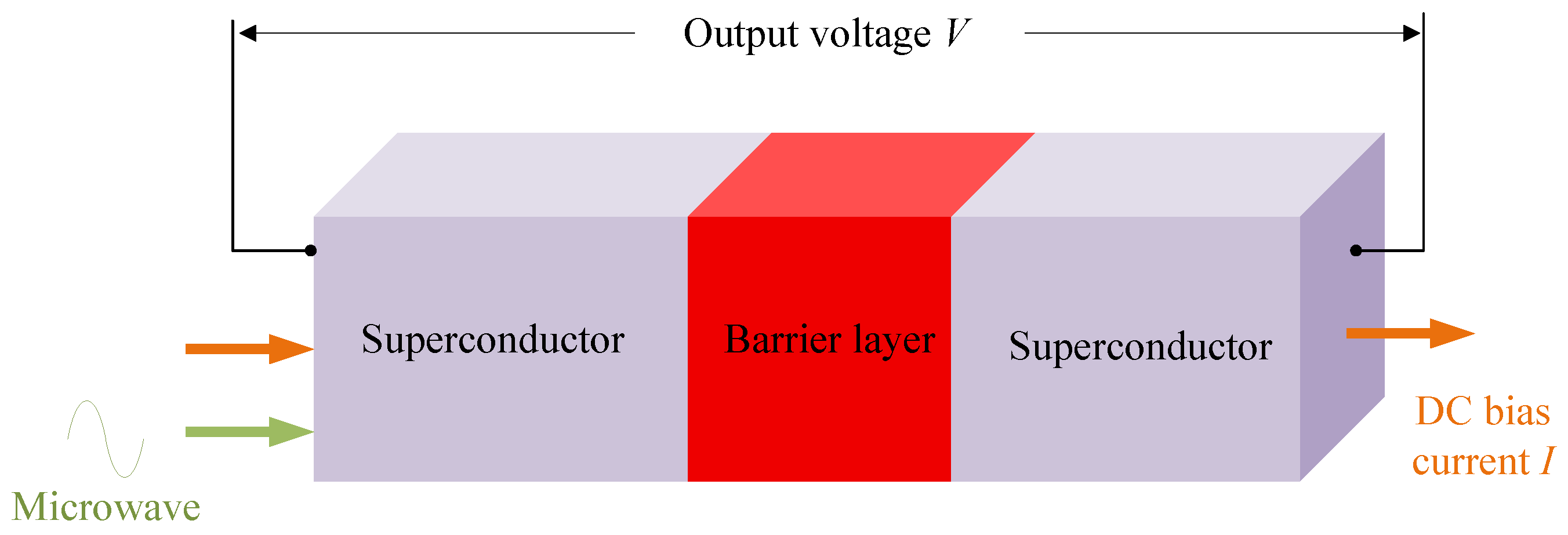
The Josephson effect is a macroscopic quantum interference phenomenon in superconductivity, theoretically predicted by B. D. Josephson in 1962 [7]. It describes the unique quantum tunneling behavior of Cooper pairs (superconducting electron pairs) when two superconductors are weakly coupled by a thin insulating layer, known as a Josephson junction, as illustrated in Figure 1. The Josephson effect is a macroscopic manifestation of phase coherence in the superconducting wave function. It includes both DC and AC effects, both of which were experimentally verified in 1963 [12,13].
When the voltage across a Josephson junction is zero ( V = 0 ), a dissipationless DC supercurrent exists. This current is determined by the phase difference and can be expressed as:
I = I c sin ( ϕ )
where I c is the critical current of the Josephson junction. This demonstrates that a supercurrent can flow through an insulating barrier without any voltage applied across the junction, a phenomenon known as the DC Josephson effect.
When a DC voltage V is applied across the Josephson junction, it exhibits the AC Josephson effect. In this regime, the phase difference evolves linearly with time, and a high-frequency supercurrent is generated within the junction. Its frequency is strictly proportional to the applied voltage, governed by the relation:
V = h 2 e f J
where f J is the frequency of the high-frequency supercurrent; h is the Planck constant; and e is the elementary charge.
When the Josephson junction is irradiated with microwaves of frequency f, its dynamics are modulated. Under appropriate microwave power, a series of voltage steps appear on the IV characteristic curve. The voltage at these steps remains constant regardless of the current (zero slope), and the steps are known as Shapiro steps. These steps occur when the frequency f J of the internal AC Josephson oscillation satisfies an integer multiple relationship with the external microwave frequency f. The voltage of the nth step is quantized and given by:
V n = n h 2 e f ( n = 0 , ± 1 , ± 2 , )
Based on the AC Josephson effect, the Josephson voltage standard operates by precisely controlling a microwave frequency f, which is traceable to the time standard, to reproduce a quantized voltage V n whose value depends solely on the fundamental constants e and h.
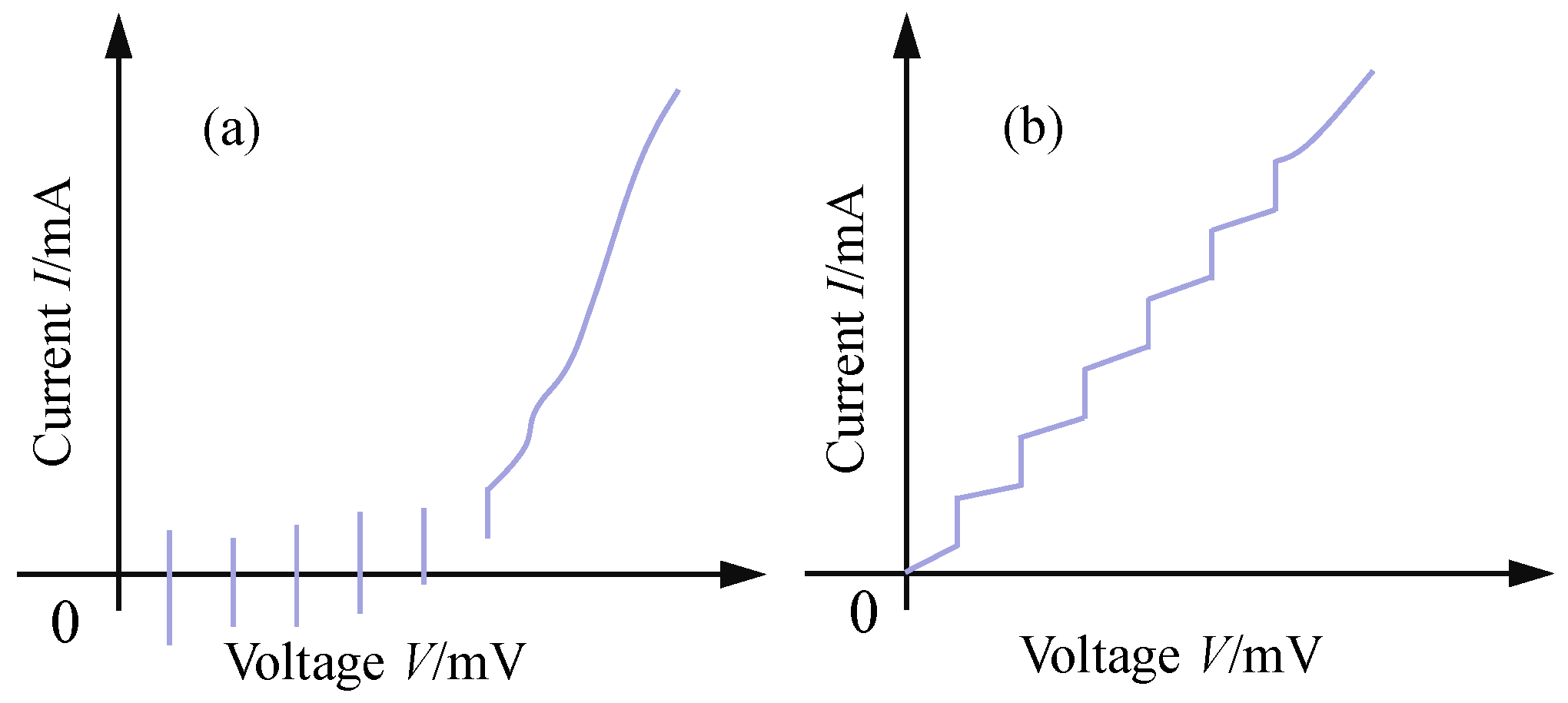
Josephson junctions are further categorized as underdamped or overdamped junctions, whose IV characteristics differ significantly, as shown in Figure 2. For underdamped Josephson junctions, the generated voltage steps overlap and cross the zero-current axis. This allows quantized voltage steps to be output even without a DC bias current. In contrast, the voltage steps of an overdamped junction do not overlap. By controlling the DC bias current, specific quantized voltage steps can be selectively and flexibly generated.

2.2. Conventional Josephson Voltage Standard

In 1972, the United States redefined the voltage unit “volt” based on the Josephson effect, thereby marking the beginning of research on quantum-metrological standards that use this effect [14]. As the first Josephson quantum voltage standard to be developed, the CJVS adopts SIS (superconductor-insulator-superconductor) Josephson junctions. When driven by a microwave source, the CJVS generates a quantized DC voltage. Notably, SIS-type Josephson junctions exhibit underdamped characteristics, which give rise to a hysteresis effect in their current-voltage (IV) characteristic curve, as illustrated in Figure 2a.
The hysteresis effect of SIS-type Josephson junction arrays endows them with two distinct characteristics. First, when SIS-type Josephson junction arrays are driven by a microwave source for a given bias current, multiple possible quantized voltage step outputs exist, as shown in Figure 2a, which makes it difficult to flexibly and efficiently generate a specific quantized voltage step. This characteristic hinders the realization of programmable voltage output. Second, quantized voltage steps can still be output when the DC bias current is zero. Consequently, quantum voltage standards based on SIS-type Josephson junction arrays can reliably generate DC quantum voltage without a DC bias current. If the system is subjected to external electromagnetic interference, the quantized voltage steps may jump or switch. In such cases, fine adjustment of the bias parameters is required to restore the system to its previous quantum-voltage output state, and this adjustment is both complex and time-consuming.
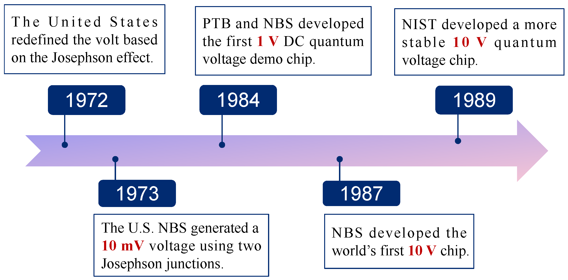
Research on the CJVS has evolved from single junctions to large-scale arrays, with the output quantum voltage gradually increasing from the millivolt level to the 10 V level. An overall development timeline is shown in Figure 3.
In 1973, the U.S. National Bureau of Standards (NBS, the predecessor of the National Institute of Standards and Technology, NIST) employed two Josephson junctions to generate a 10 mV voltage and achieved the calibration of a 1 V electrochemical cell [15]. To achieve a higher-amplitude quantized voltage, metrologists proposed that connecting multiple well-matched Josephson junctions in series and driving them with a single microwave signal could generate a larger quantum voltage with zero bias current. This approach eliminates the need to individually adjust the bias current for each junction, offering a simpler and more practical solution. This idea provided important insight for advancing Josephson quantum voltage standards toward practical applications at the 1 V and 10 V levels.
In 1984, the Physikalisch-Technische Bundesanstalt (PTB) and NBS jointly developed the first demonstration chip for a quantum voltage standard, which achieved a 1 V DC quantized voltage output [16]. The chip comprised 1474 Josephson junctions with electrodes fabricated from a lead-indium-gold alloy. However, this array was not yet fully practical, as the junctions tended to switch spontaneously between different voltage levels, compromising the long-term stability of the output. Through subsequent technical iteration, NBS introduced the world’s first practical, stable, and user-friendly 1 V standard device in 1985 [17]. This device integrated 1484 junctions consisting of niobium and lead-indium-gold superconducting electrodes separated by niobium oxide insulating layers. Such series-array microchips subsequently became the cornerstone of global voltage calibration, finding widespread application in national, industrial, and military laboratories.
In 1987, NBS fabricated the world’s first 10 V Josephson array chip, comprising 14,184 junctions [18]. Each junction was constructed with a niobium electrode, a niobium oxide barrier layer, and a lead-indium-gold counter electrode, and the Josephson array was driven by a 70 GHz microwave signal. The DC quantum voltage standard built with this chip enabled direct calibration of 10 V Zener reference standards without requiring a voltage divider. In 1989, NIST developed the first 10 V chip based on niobium-aluminum oxide-niobium Josephson junctions, integrating a total of 18,992 junctions. The new Josephson array design employed in this chip yielded a more stable output voltage and lower microwave power consumption [19]. A quantum voltage standard implemented with this chip calibrated 10 V Zener cells with a measurement uncertainty of 4 × 10 9 , which was dominated by the noise of the Zener devices. In 1990, NIST published a comprehensive description covering the Josephson array design, cryogenic probe preparation, requirements for the bias current source, system performance tuning, calibration algorithms, and error evaluation [20].
As the first type of Josephson voltage standard studied in depth, the CJVS has been successfully employed by several countries to establish their national DC voltage standards. Results from international comparisons indicate that the consistency between different CJVS systems reaches the 10 10 level, signifying that the reproduction of DC voltage based on the Josephson effect has achieved extremely high accuracy [21] and plays a vital role in maintaining the consistency of voltage values worldwide. The functionality of the CJVS is relatively limited, as it can generate only discrete, fixed-voltage outputs and cannot produce programmable or arbitrary quantum-voltage waveforms. In addition, the CJVS has a lower level of automation than PJVS and JAWS, and it still requires cryogenic operation, typically using liquid helium. These limitations restrict its flexibility in modern automated calibration systems and make it unsuitable for AC, broadband, or dynamic waveform applications. The typical characteristics of CJVS are presented in Table 1.

2.3. Programmable Josephson Voltage Standard

DC quantum voltage standards are inherently limited to generating discrete voltage steps, which constrains their flexibility in modern precision engineering and automated metrology. To address this limitation, programmable quantum voltage output has become a key technological goal, leading to the development of more versatile and practical programmable Josephson voltage standards.
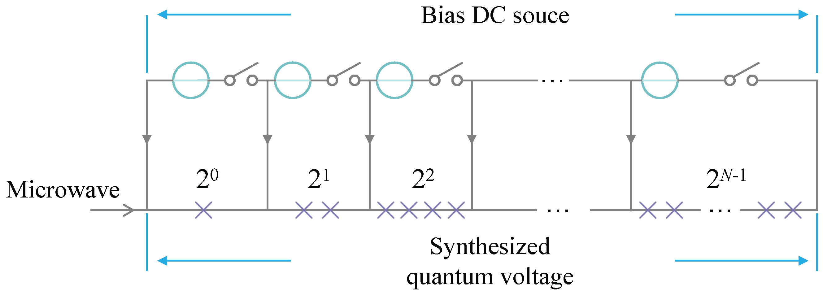
In 1995, Hamilton et al. at NIST first proposed a method for programmable synthesis of quantum voltage using a Josephson digital-to-analog converter [22]. The scheme employs an array of overdamped Josephson junctions configured in a binary sequence to construct a 14-bit digital-to-analog converter. Using thirteen bias lines, any value within the range of −8192 to +8192 (corresponding to approximately −1.2 V to +1.2 V) can be selected within the stabilization time of the bias current (a few nanoseconds). This circuit enables the digital synthesis of high-accuracy AC waveforms. As shown in Figure 4, when a Josephson junction array is divided into N sub-arrays in a binary scheme, the k-th sub-array contains 2 k 1 Josephson junctions. The total output voltage V synthesized by the PJVS is given by the following formula:
V = h 2 e f k = 1 N 2 k 1 δ k
where δ k is the bias state of the k-th sub-array, and its value can be 0, + 1 , or 1 .
PJVS synthesizes quantized step voltages that approximate the shape of a target waveform by presetting appropriate DC bias currents for different Josephson junction arrays. To achieve programmable output, the junction array must be divided into multiple sub-arrays. The earliest division method employed the binary ascending rule, where the number of junctions in the i-th sub-array is N i = 2 i × N LSB ( N LSB is the number of junctions in the smallest sub-array), thereby defining the voltage resolution of the system [23]. The corresponding binary combination algorithm first calculates the total effective number of positively biased junctions N corresponding to the target voltage. The quotient of N divided by N LSB is then converted into a binary number. The “1” or “0” in each bit of this binary number corresponds to the “positive bias” or “zero bias” state of the respective sub-array.
To use all three bias states, i.e., positive, zero, and negative ( + 1 , 0, 1 ) simultaneously, NIST proposed a ternary ascending array design ( N i = N LSB · 3 i ) and a corresponding balanced ternary bias combination algorithm [24]. This algorithm converts the calculated value into a balanced ternary number. The digits 1 , 0, and + 1 in this number correspond to the negative bias, zero bias, and positive bias states of the sub-arrays, respectively. Compared to binary arrays, ternary arrays require fewer sub-arrays to output the same voltage, leading to a simpler drive system design, and have therefore been adopted by more national metrology institutes. This principle can be further extended to quinary division to use even more biased states [25].
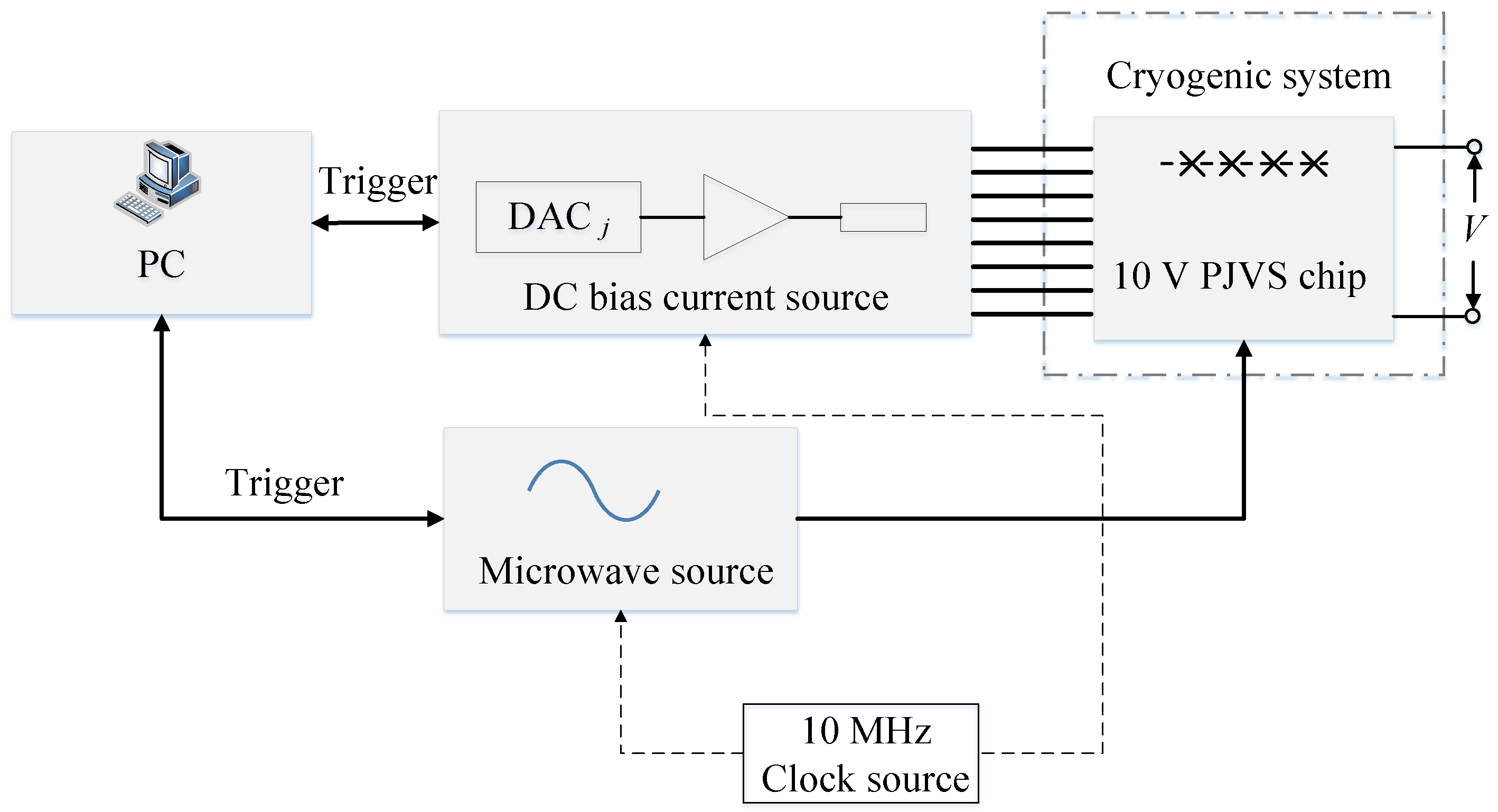
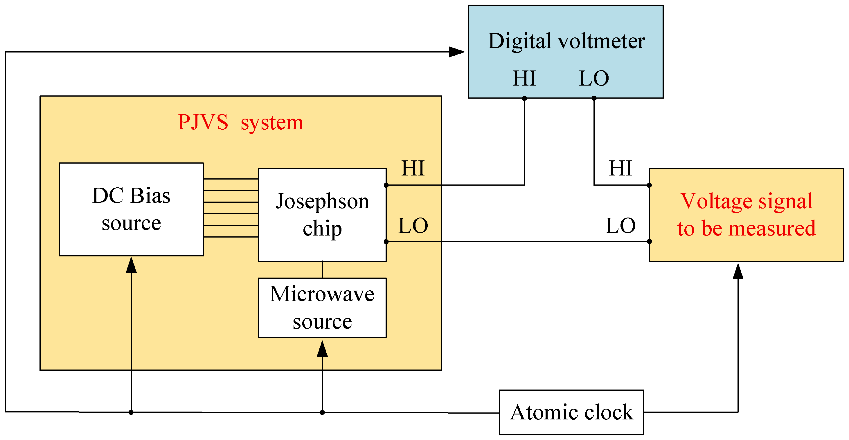
The overall architecture of the PJVS is illustrated in Figure 5. It primarily consists of the PJVS chip (Josephson junction array), the cryogenic refrigeration system, the microwave source, the DC bias current source, the reference clock, and the central control system. Among these, the cryogenic refrigeration system, which can be constructed using liquid helium [26,27] or a cryocooler [28,29], maintains a stable cryogenic environment (∼4 K) to provide the necessary superconducting conditions for the PJVS chip. The microwave source drives the Josephson junction array, inducing it to produce multi-state quantized voltage steps, as shown in Figure 2b. The DC bias current source is capable of high-precision output of multi-channel DC bias currents [30,31]. Each channel independently controls the quantum state of its corresponding Josephson sub-array, making it the key component for manipulating the programmable output of the quantum voltage standard.
The design of Josephson junction arrays primarily follows three technical approaches. First, the Nb/ Nb x Si 1 x /Nb tunnel junction (SNS-type) adopted by NIST can generate quantum voltage steps with a width of approximately 1 mA under microwave drive at around 20 GHz [26]. Second, PTB has employed both Nb-Al/ Al 2 O 3 (SINIS-type) [32] and later SNS-type junctions [33], but with a significantly higher drive frequency of 70 GHz. Third, the NbN/ TiN x /NbN junction (SNS-type) [34] used by Japan’s National Metrology Institute of Japan (NMIJ) and the National Institute of Advanced Industrial Science and Technology (AIST) (NMIJ/AIST) offers the advantage of operating at temperatures up to 10.2 K (with a microwave frequency of 16 GHz), which facilitates system miniaturization, although its fabrication is more challenging.
Currently, leading international institutions have all achieved 10 V-level PJVS systems, albeit via different technical paths. NIST’s 10 V Josephson array integrates over 260,000 junctions, uses 18–20 GHz microwave drive, and employs Wilkinson power dividers for microwave distribution [35,36]. PTB, utilizing a high-frequency 70 GHz drive and a parallel microstrip antenna design, achieved 10 V output with a single-layer array of fewer than 70,000 junctions, and its double-layer stacked design further increased the output voltage to 20 V [33,37,38]. Japan’s NMIJ/AIST has integrated over 520,000 junctions to achieve a 17 V DC voltage output under 16 GHz drive [39] and has developed a novel power divider to optimize microwave distribution uniformity [40]. Furthermore, Italy’s Istituto Nazionale di Ricerca Metrologica (INRIM), in collaboration with PTB, has developed an SNIS-type junction array [41], while Russia’s Kvartz Institute (KVARZ) has successfully demonstrated a quantum voltage standard principle based on the high-temperature superconductor Y Ba 2 Cu 3 O 7 operating at 77 K [42].
PJVS technology has now matured and is moving toward practical application and commercialization. Compact, automated systems based on cryocoolers and requiring no liquid helium have been developed by institutions such as NMIJ/AIST, NIST, and Germany’s Supracon. NIST and Supracon are currently advancing their commercialization [43,44], laying the groundwork for the widespread adoption of quantum voltage standards.
In the early stage of establishing quantum voltage standards in China, PJVS systems were developed using foreign quantum voltage chips. In 2009, the National Institute of Metrology (NIM) of China established a 1.2 V PJVS system based on SINIS junction arrays. In 2013, NIM introduced a 10 V quantum-voltage standard system from NIST and subsequently conducted research on voltage measurement techniques based on this system [45]. As a result, China has achieved a relatively mature capability in the construction of peripheral measurement and control components, including cryogenic thermostats, bias current sources, and quantum voltage generation algorithms. A certain gap remains between China and leading international levels in PJVS chip technology. Since 2011, NIM has devoted substantial effort to developing Josephson junction arrays based on Nb/ Nb x Si 1 x /Nb technology. In 2018, NIM successfully fabricated a DC Josephson junction array and achieved a 0.5 V DC quantum voltage output [46]. In 2022, NIM proposed a balanced segmentation scheme to improve microwave transmission and fabricated a 2 V programmable Josephson junction array based on double-stacked Josephson junctions and a ternary-divided sequence [47]. The quantum locking current range of the full array exceeded 1.5 mA, and the circuit could be programmed to output DC voltages and AC stepwise waveforms over the range from −2 V to 2 V, demonstrating its potential for programmable quantum voltage standards. At present, China is capable of stable production of 2 V PJVS chips, while continued efforts are being made toward 10 V chips to meet the growing demands of diverse voltage metrology applications.
The PJVS combines high accuracy with excellent programmability, making it an important bridge between conventional DC quantum voltage standards and AC quantum voltage metrology. By using binary Josephson junction arrays driven by RF signals, PJVS can generate programmable quantized voltages up to approximately 10 V, covering both DC and low-frequency AC applications up to about 1 kHz. Its high level of automation and uncertainty on the order of 10 10 for DC and 10 8 for low-frequency AC measurements make it suitable for AC voltage calibration and quantum AC voltage standards. However, PJVS generates a step-approximated voltage waveform by switching the quantum state of Josephson junction arrays, and due to the step-switching operation, the frequency of the generated voltage signal is limited to within 1 kHz, which limits its use in broadband and complex dynamic signal measurements. Moreover, its measurement uncertainty increases with frequency. Table 1 presents the fundamental characteristics of PJVS.

2.4. Josephson Arbitrary Waveform Synthesizer

In 1996, Hamilton et al. at NIST demonstrated the first Josephson arbitrary waveform synthesizer, commonly referred to as JAWS [48]. Operating on the magnetic flux quantum principle, JAWS employs a train of high-speed current pulses to excite a Josephson junction array and generate corresponding voltage signals. When the current pulse amplitude falls within the first Shapiro step of the junction, each junction produces a quantized voltage pulse whose time-integrated area is precisely calculable. This fundamental quantization enables JAWS to synthesize spectrally pure AC quantum voltages, with a theoretical spurious-free dynamic range of up to 116 dBc [49].
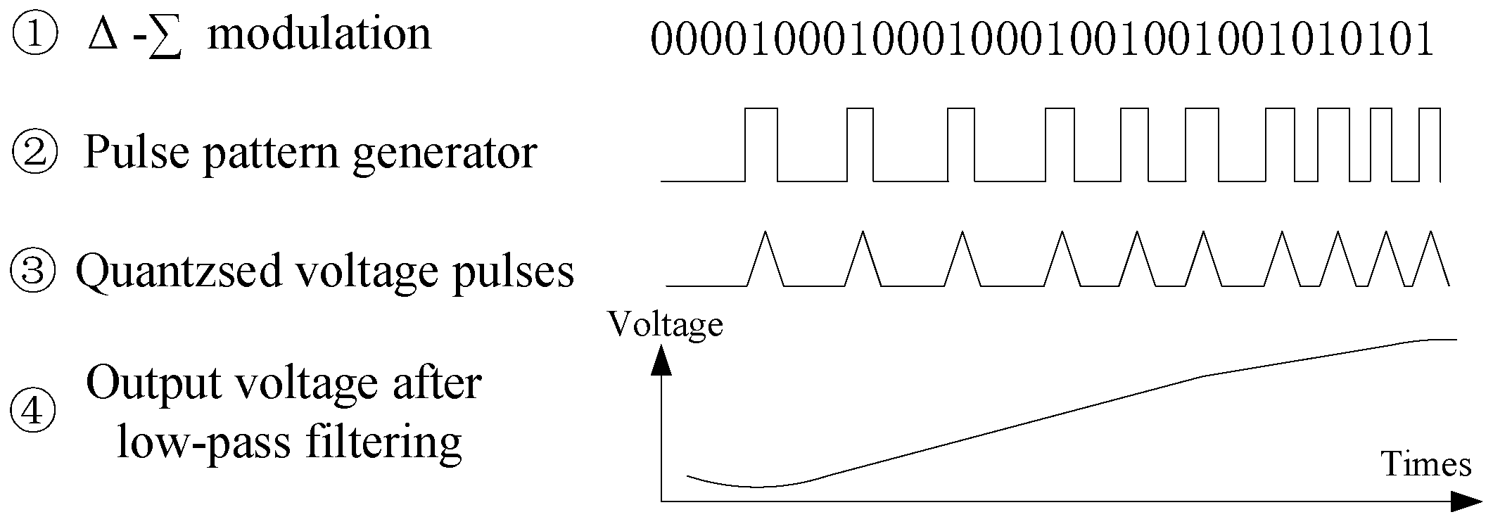
The synthesis of a target quantum voltage waveform using JAWS follows a four-step procedure, as shown in Figure 6. First, the desired analog voltage waveform is encoded into a sequence of digital codes via a modulation process. These codes are then stored in a pulse pattern generator, which converts them into a precise series of high-speed current pulses. Third, these current pulses drive the Josephson junction array, generating a sequence of quantized voltage pulses. Finally, a low-pass filter is applied to the pulse sequence to attenuate high-frequency quantization noise, yielding the final high-fidelity quantum voltage waveform [50].
In the development of JAWS, the output voltage amplitude is typically lower than that of PJVS, a limitation rooted in their fundamental operating principles. JAWS synthesizes arbitrary waveforms by driving Josephson junctions with ultrashort microwave pulses. The instantaneous output voltage is determined by the area of a single pulse, which physically constrains the peak voltage. More critically, the broadband pulse driving required for arbitrary waveform generation makes the system highly sensitive to non-ideal characteristics of the junction array. Consequently, unlike PJVS, JAWS cannot substantially increase the total voltage simply by connecting a very large number of junctions in series, making output amplitude an inherent bottleneck.
To overcome this amplitude limitation, technological advances have primarily focused on three directions. For Josephson junction array design, efforts include integrating larger numbers of Josephson junctions (e.g., NIST integrated 102,480 junctions to achieve 2 V output [51], while PTB used 63,000 junctions for 1 V output [49]) and adopting three-dimensional integration processes such as vertical stacking. These approaches increase junction density within a limited area and improve microwave excitation uniformity [52]. For drive-signal distribution, the core challenge is ensuring uniform microwave energy delivery to each junction. The technological path has evolved from multi-channel independent driving [53] to the use of monolithically integrated power dividers [54]. The latter significantly simplifies the system but imposes stringent requirements on circuit uniformity, often requiring compensation techniques such as pulse shaping [54]. In driving methodologies, the approach has progressed from relying on external compensation current sources [55] to designing intelligent pulse sequences with embedded compensation [56,57]. This improves waveform synthesis accuracy while simplifying the system architecture. JAWS is now capable of generating GHz-frequency voltage signals [58,59], providing vital support for radio, radar, and qubit readout and control. Recent efforts have focused on novel approaches such as optical driving, which replaces electrical pulses with optical stimuli to substantially mitigate electromagnetic interference [60,61]. Internationally, leading institutions including NIST and PTB have advanced JAWS output voltages to the 1–2 V a root mean square (RMS) range and are progressing toward commercialization using cryocooler-based systems [62].
The NIM of China initially established JAWS systems using quantum voltage chips fabricated by NIST, and carried out related studies on chip driving and applications [63]. Reference [56] proposed a dual-pulse driving method to eliminate low-frequency current components, thereby removing the need for both a low-frequency compensation current source and a DC current source. This further simplified the JAWS system architecture and provided important support for quantum noise thermometry. Through these studies, China has achieved autonomous and reliable driving of JAWS quantum chips and has accumulated substantial experience in cryogenic refrigeration, pulse-drive control, and arbitrary quantum-voltage waveform synthesis. On this basis, NIM has continued to advance the domestic fabrication of JAWS quantum chips. In 2025, NIM adopted an on-chip Wilkinson power divider, internal/external DC blocks, and a tapered coplanar waveguide design, which improved chip integration, reduced the number of data input channels, and enhanced microwave transmission uniformity along the long junction arrays. The fabricated chip integrated 16,000 double-stacked Nb/ Nb x Si 1 x /Nb Josephson junctions and was capable of synthesizing a low-distortion sinusoidal voltage with an RMS value of 300 mV, demonstrating the application potential of domestically developed JAWS chips for AC quantum voltage synthesis [64]. In the future, the development of JAWS quantum chips with higher output amplitude, lower distortion, and higher integration density will remain an important research direction.
JAWS offers the unique advantage of directly synthesizing quantum-accurate arbitrary waveforms through pulse-driven Josephson junction arrays. Compared with PJVS, JAWS provides a much broader frequency capability, extending from DC to several GHz, and is therefore particularly promising for broadband waveform generation, dynamic signal calibration, and characterization of metrological devices with wideband responses. Its high level of automation and arbitrary waveform capability make it a powerful candidate for future quantum-based AC and broadband electrical metrology. Nevertheless, JAWS also has important limitations. Its output voltage amplitude is still relatively low, typically not exceeding about 4 V, which restricts its direct use in some practical calibration scenarios. In addition, the system is highly complex, involving demanding pulse generation, broadband microwave transmission, synchronization, cryogenic operation, and waveform reconstruction. Its uncertainty also depends strongly on waveform type and operating conditions, generally ranging from 10 8 to 10 6 , which indicates that standardized high-precision applications are still under further development.

3. Comparison of Josephson Voltage Standards

Mutual consistency among reproduced voltages is a critical requirement for all types of Josephson quantum voltage standards and forms a cornerstone of their scientific and practical legitimacy. This section reviews intercomparison studies that verify agreement and equivalence among the primary system variants, namely the CJVS, PJVS, and JAWS.
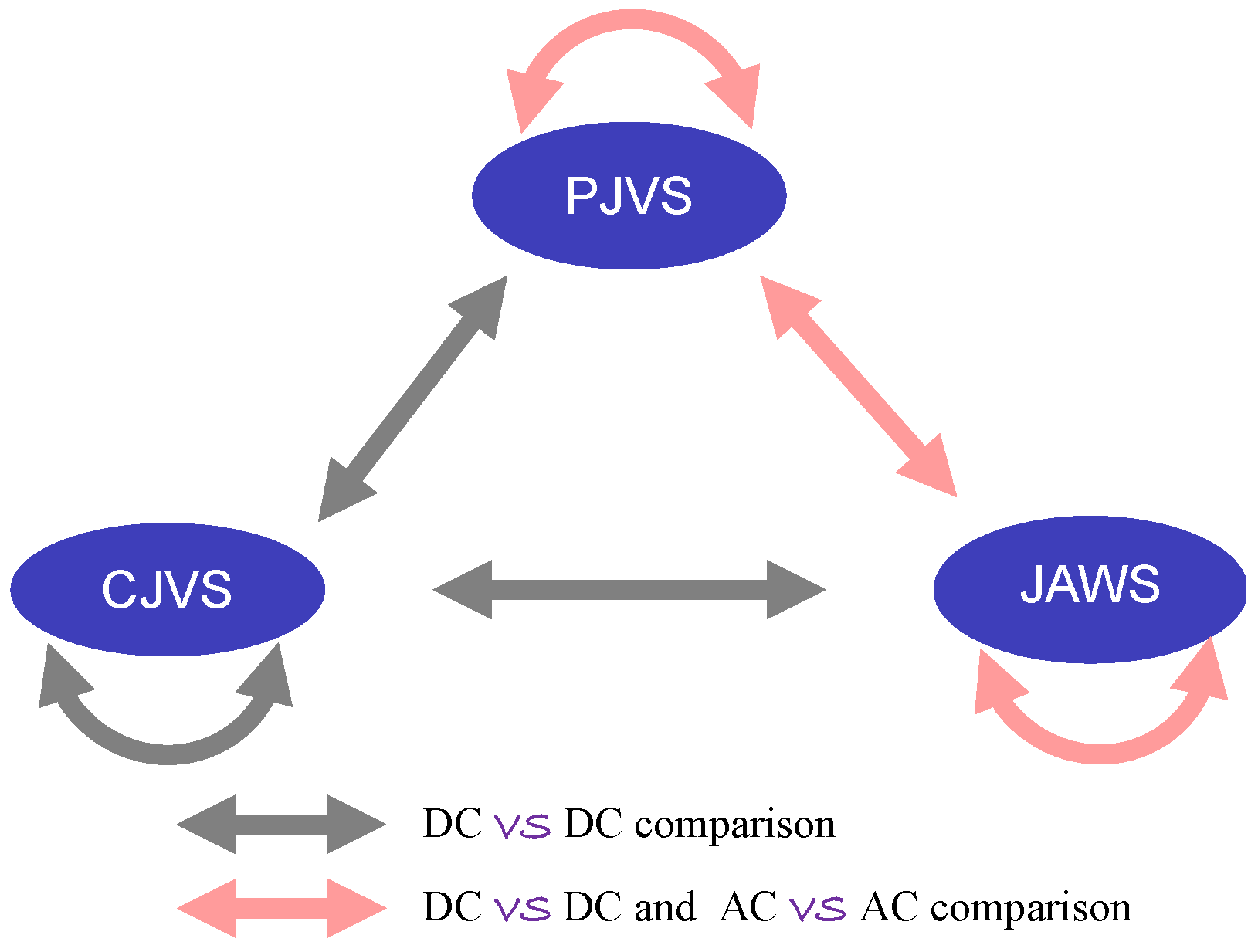
Figure 7 depicts the intercomparison paradigm. In this configuration, solid gray arrows represent comparisons of DC quantum voltages, while light red arrows denote comparisons between DC and AC quantum voltages. Because PJVS and JAWS generate step-approximated and sinusoidal AC voltages, respectively, AC comparisons can be categorized into three types: step-approximated vs. step-approximated, sinusoidal vs. step-approximated, and sinusoidal vs. sinusoidal.

3.1. Comparison Between DC Quantum Voltages

Since CJVS, PJVS, and JAWS share the common capability of DC voltage synthesis, their intercomparison is a direct procedure. The prevailing method follows the BIPM protocol [65], using a transferred CJVS for on-site comparison. The core procedure involves connecting the two systems in reverse series, generating opposing DC quantum voltages, and measuring the resultant residual voltage with a null detector to evaluate their mutual consistency.
Over the past two decades, the International Bureau of Weights and Measures (BIPM) conducted 41 on-site comparisons between CJVS systems, achieving agreement at the 10 10 level [21]. To reach this high degree of consistency, several technical factors proved critical, including proper grounding, effective filtering, high insulation resistance of the measurement leads, and well-controlled microwave distribution to the Josephson arrays.
DC comparisons between PJVS and CJVS systems, as well as among different PJVS systems, have been completed in multiple national metrology institutes and calibration laboratories [66,67,68,69]. Since JAWS and PJVS use distinct microwave-drive strategies, DC comparisons between them serve to verify the operational correctness of JAWS as a quantum voltage standard [70]. Selected results from these JVS intercomparisons are summarized in Table 2.

3.2. Comparison of Staircase Voltages

By comparing the consistency of quantized voltage steps generated by different PJVS systems, the correctness and reliability of JVS systems as quantum voltage references can be further validated. The comparison of step-approximated voltage waveforms between two PJVS systems is performed indirectly using a differential sampling technique, in which the two systems successively measure the same high-stability AC voltage signal. Within this framework, the BIPM and PTB successfully conducted the first key comparison for PJVS [71]. At a RMS voltage of 0.75 V and a frequency of 62.5 Hz, the result was ( 1 ± 2.5 ) × 10 8 (k = 1). At 1 kHz, the result was ( 3.7 ± 1.7 ) × 10 8 (k = 1). When the RMS voltage was increased to 7 V, the measured result at 62.5 Hz was ( 2.6 ± 2.7 ) × 10 8 (k = 1), and at 1 kHz it was ( 2.4 ± 3.3 ) × 10 8 (k = 1). It should be noted that the overall accuracy of this comparison is primarily limited by the performance of the digital sampler itself, including factors such as its stability, noise, nonlinearity, and gain errors. For clarity, the comparison results between PJVS systems are presented in Table 2.

3.3. Comparison Between Staircase Voltage and Smooth Sinusoidal Voltage

Comparing the AC voltage signals generated by JAWS and PJVS can verify the equivalence of these two JVS systems. In the first comparison experiment between JAWS and PJVS, sinusoidal AC voltage waveforms with an RMS value of 100 mV and a frequency of 50 Hz were compared. The experiment employed an analog-to-digital converter as a transfer standard to alternately measure the step-approximated AC voltage waveform generated by the PJVS and the sinusoidal AC voltage waveform generated by JAWS. The results showed that the agreement in fundamental voltage amplitude was ( 0.18 ± 0.13 ) × 10 6 (k = 1) [72]. Subsequently, other researchers directly adopted a differential sampling technique, using a PJVS-based quantum voltmeter to measure the sinusoidal AC voltage waveform generated by JAWS. When comparing sinusoidal waveforms with an amplitude of 1 V and a frequency of 250 Hz, an agreement in fundamental voltage amplitude of ( 3.5 ± 11.7 ) × 10 9 (k = 1) was achieved [73].
Due to the low amplitude of the JAWS output waveform and the limited frequency range of PJVS output, the JAWS vs. PJVS comparison scheme is practically more suitable for low-frequency, small-amplitude voltage comparisons. Some of the comparison results are listed in Table 2.

3.4. Comparison Between Smooth Sinusoidal Voltages

To compare two sinusoidal AC voltage signals, the junction arrays of two JAWS can be connected in series with their output voltages set to a phase difference of 180 . This method requires strict synchronization between the two JAWS systems, necessitating precise adjustment of the relative phase of their output waveforms to minimize the differential signal.
Within this framework, several studies have successfully performed comparisons of sinusoidal voltages generated by JAWS systems. A comparison conducted under conditions of 1 V RMS and 1 kHz demonstrated an agreement of 8 × 10 8 between the output voltages of the two systems [74]. Another study employed a high-precision analog-to-digital converter (ADC) as a transfer standard, comparing the output signals of two JAWS systems through alternating measurements. The resulting Type A standard uncertainty was 0.4 μV/V, primarily limited by factors such as ADC nonlinearity and noise [76]. Furthermore, a comparison experiment based on frequency-domain cross-correlation technology, conducted within a frequency range of 0.48 kHz to 5 kHz and at an RMS voltage value of 20 mV, yielded an agreement of ( 5.8 ± 8 ) × 10 8 (k = 1) [75]. Some comparison results between sinusoidal AC voltage waveforms generated by JAWS systems are presented in Table 2.

4. High-Precision Voltage Measurement Using the Josephson Voltage Standard

4.1. Differential Sampling Measurement of AC Voltage Using the Josephson Voltage Standard

Accurate voltage measurement is fundamental to a wide range of applications in research, industry, and manufacturing. Compared with JAWS, the PJVS has a simpler structure and has been widely adopted in various areas of electromagnetic measurement. The differential sampling method for AC voltage measurement was pioneered by Ralf Behr in 2007 [77], leveraging a high-accuracy, PJVS-generated staircase waveform to approximate the AC voltage signal.
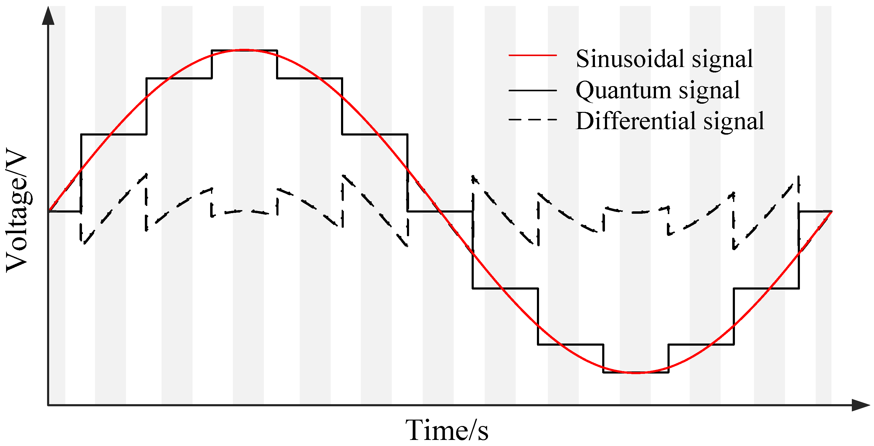
The principle of PJVS-based differential sampling measurement for AC voltage is illustrated in Figure 8. The black solid line represents the step-approximated sinusoidal voltage generated by the PJVS, while the red solid line denotes the sinusoidal voltage to be measured. The black dashed line indicates the differential signal between the two waveforms, and the gray rectangular boxes highlight the stable data regions corresponding to each quantum voltage step.
The core procedure of the differential sampling method is as follows. First, the characteristics of the target AC signal are analyzed. Based on this analysis, the PJVS generates a standard stepwise voltage waveform that approximates the AC signal. This reference signal is subtracted from the measured signal, leaving only the differential component to be sampled. Finally, by adding the sampled differential signal to the known PJVS step voltage, the original sinusoidal voltage is reconstructed with high accuracy.
Figure 9 illustrates the schematic of the PJVS-based differential sampling measurement system. By measuring the small differential voltage signal, the PJVS-based differential sampling method significantly reduces the influence of sampler nonlinearity [78], thereby improving the accuracy of AC voltage measurement. During this process, the differential signal is sampled only within the stable regions corresponding to the quantum voltage steps.
The differential sampling technique can also be implemented using a JAWS system to measure AC voltage. The measurement principle is similar to that illustrated in Figure 8, with the PJVS replaced by JAWS. Researchers at NIST employed this JAWS-based differential method to measure a 1 V RMS, 1 kHz AC voltage, attaining a Type A uncertainty of 45 nV/V over a 10-min measurement [79]. To further reduce the differential signal, an iterative phase alignment procedure between the JAWS output and the voltage to be measured is introduced during the measurement process.

4.2. Coherent Subsampling for Extending AC Voltage Measurement Bandwidth

Due to limitations imposed by transient processes and the Gibbs phenomenon, the PJVS-based differential sampling method was initially limited to measuring AC voltages at frequencies of only about 1 kHz. Achieving accurate measurements at higher frequencies is crucial for applications such as broadband power and impedance measurement. This need has driven metrologists to explore methods for calibrating high-frequency sinusoidal signals using low-frequency PJVS-generated quantum voltage.
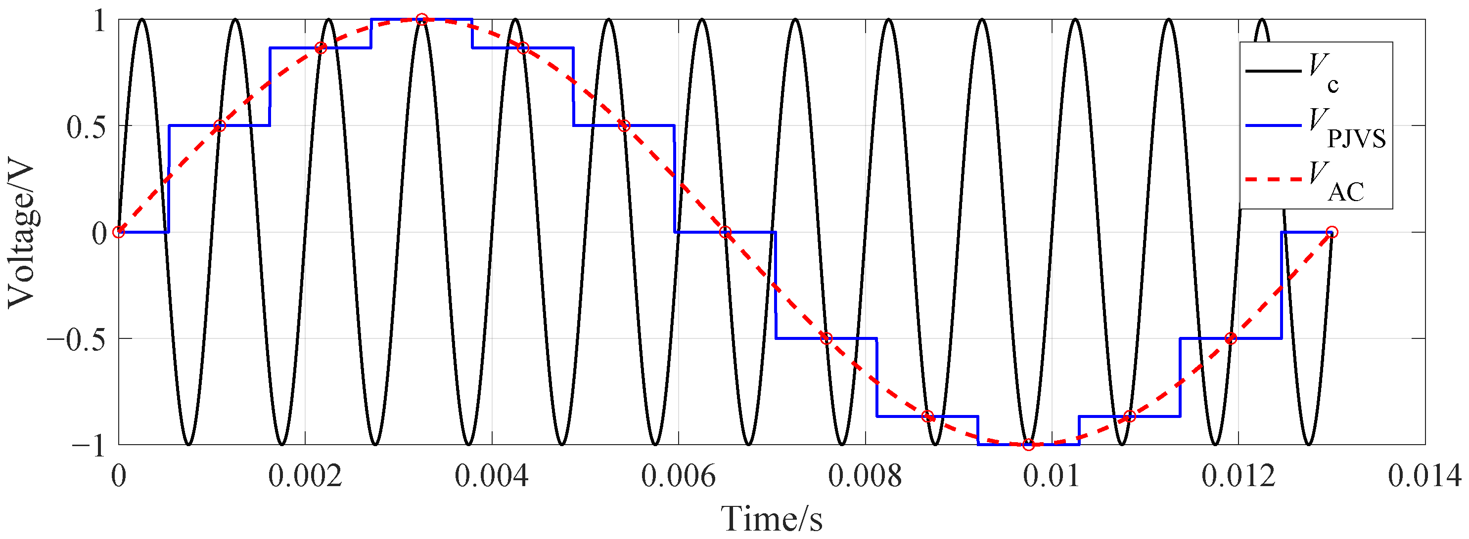
In 2016, researchers at Brazil’s National Institute of Metrology, Quality and Technology (INMETRO) proposed a coherent subsampling method to extend the frequency range of AC voltage calibration based on PJVS [80]. The basic principle is illustrated in Figure 10. Specifically, a frequency relationship is established between the fundamental frequency f J of the PJVS-generated staircase voltage waveform and the frequency f n of the sinusoidal voltage signal to be measured:
f n = ( n N + 1 ) f J
where n is any positive integer, and N is the number of quantum voltage steps within one fundamental period of the PJVS output. In the example of Figure 10, n = 1 and N = 12 .
From Equation (5), the period relationship can be derived as
T J = ( n N + 1 ) T n
where T J is the fundamental period of the PJVS-generated staircase voltage waveform, and T n is the period of the high-frequency sinusoidal voltage to be measured.
The core principle of the PJVS-based coherent subsampling method is to use the frequency relationship described in Equation (5) for measurement or calibration. As shown in Equation (5), within one PJVS fundamental period, the high-frequency voltage to be measured completes exactly n N + 1 full cycles. Consequently, during a single PJVS quantum voltage step, the high-frequency voltage to be measured undergoes n full cycles plus a fractional 1 / N cycle, which is the key to measuring high-frequency voltage with a low-frequency voltage standard.
Because both the PJVS-generated quantum voltage signal and the high-frequency voltage to be measured are coherent, subsampling can be performed within a single PJVS fundamental period. The two signals are coarsely aligned by a careful phase adjustment, positioning the first sampling point at the 0 V quantum voltage step. Within one full PJVS-generated voltage signal period, the two waveforms intersect at 2 N points (N points in each half-cycle). At each intersection point, the differential voltage V diff = V PJVS V A C is recorded. Since V PJVS is a known, quantum-traceable value, the actual voltage of the high-frequency voltage to be measured at that point is derived as V A C = V PJVS V diff .
This process uses the coherence between the two periodic signals. By performing differential measurements at the 2 N uniformly distributed intersection points (i.e., sampling points), an effective high sampling rate for the high-frequency signal is achieved with a lower physical sampling rate. The effective sampling rate is f s = 2 N · f J . Therefore, this method enables the indirect measurement of high-frequency sinusoidal voltages up to 100 kHz by leveraging the low-frequency, high-accuracy Josephson quantum voltage standard.
The factors affecting the measurement accuracy of high-frequency AC voltage signals include the reduced resolution of ADCs operating over a wide range, the stringent phase-alignment requirement between V A C and V PJVS , frequency-dependent ADC gain errors, and timing jitter in the high-frequency voltage to be measured. The measurement capability of the coherent subsampling method was validated in [80] through comparison with a thermal converter and a Fluke 5730A calibrator. The experimental results demonstrated a relative deviation on the order of 10 6 at frequencies up to 12 kHz, and in the range of 20 kHz to 100 kHz, the relative deviation was between 10 4 and 10 5 .
PTB has explored an alternative voltage-differential subsampling approach using a PJVS-generated triangular staircase waveform [81]. The method involves driving the PJVS to generate a triangular staircase waveform and setting the measured voltage frequency to an integer multiple (e.g., 100 times) of the fundamental frequency of the PJVS-generated waveform. As the quantum voltage step changes over one triangular waveform period, the high-frequency voltage to be measured experiences corresponding voltage offsets, enabling a full-cycle scan of the measured voltage within a set voltage limit. Following the principle of “measuring a small differential voltage signal”, this method also uses only the sampled data within a specific voltage range to reconstruct the sine wave, thereby mitigating sampler nonlinearity. Precise control of the trigger acquisition timing for differential sampling is required. For measured voltages with an RMS value of 1 V and frequencies in the range of 500 Hz to 100 kHz, the measurement uncertainty is better than 5 × 10 6 (k = 1).

5. Extended Applications for Quantum Voltage Standards

5.1. Quantum Power Standard

5.1.1. Quantum Power Standard Based on the “Standard Source” Method at NIST

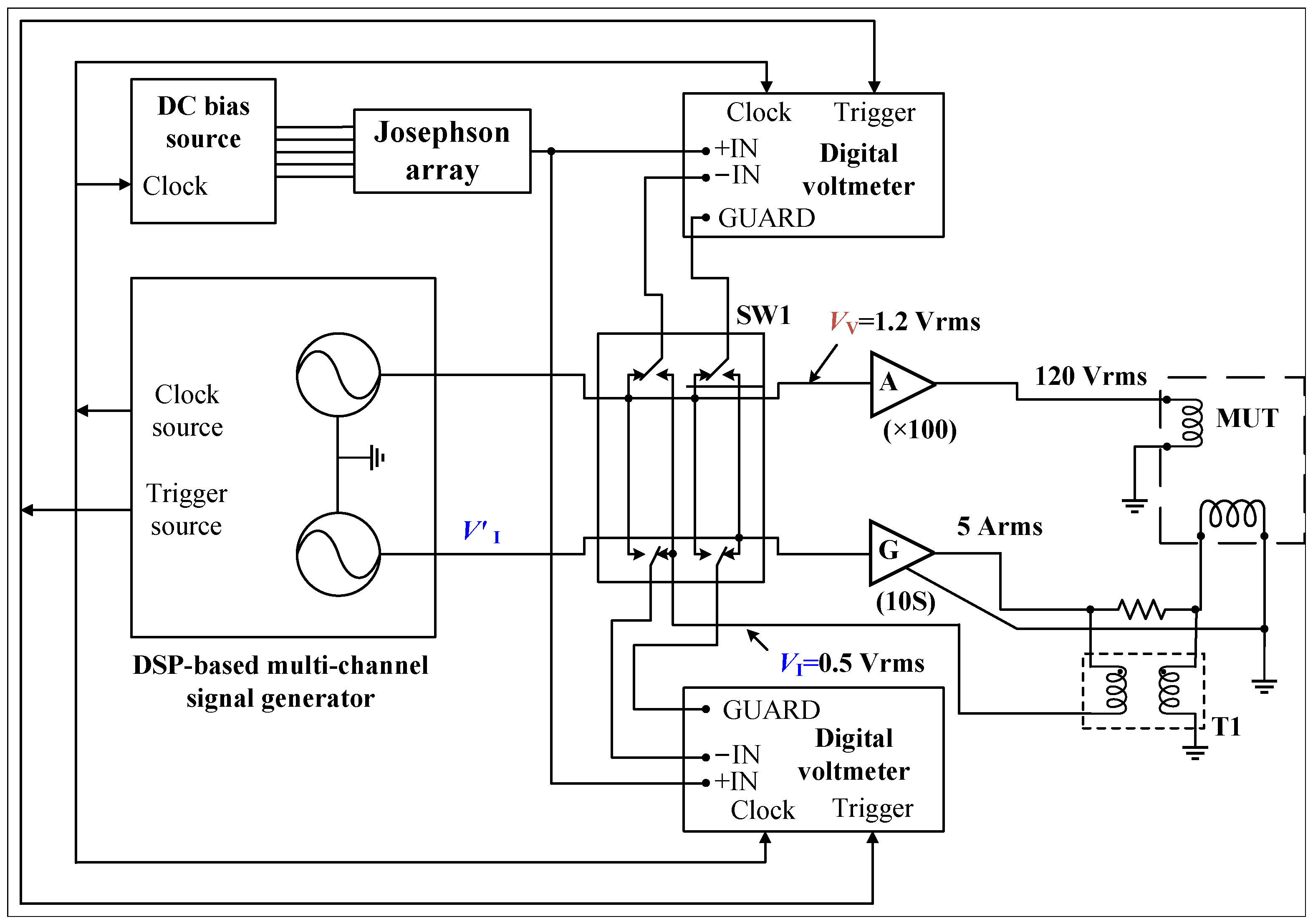
A quantum power standard operating as an accurate power source was proposed and implemented by NIST [82]. This system, with its schematic illustrated in Figure 11, delivers high-accuracy outputs of 120 V and 5 A in RMS over a frequency range of 50 Hz to 400 Hz, with a power output uncertainty better than 2 μW/VA ( k = 1 ) at 60 Hz.
As shown in Figure 11, the system employs a digital signal processing (DSP)-based multi-channel signal generator to produce two voltage signals, i.e., V V (traceable to 1.2 V in RMS) and V I (approximately 0.5 V in RMS), and their phase difference can be flexibly adjusted. V V is amplified by a precise 100× voltage amplifier to generate the 120 V applied to the Meter Under Test (MUT). V I drives a transconductance amplifier with approximately 10 S admittance to produce the 5 A output current. For current traceability, a 0.1   Ω sampling resistor ( Z s ) is used, and the voltage across it is isolated by a 1:1 voltage transformer T 1 to produce a voltage signal V I . The DSP adjusts V I to set the RMS value of V I to approximately 0.5 V.
The differential sampling method, accompanied by a PJVS, is used to accurately measure the voltage signals V V and V I . Based on these values, the DSP can then adjust the values for V V and V I precisely, thereby establishing traceability to 1.2 V and 0.5 V, respectively. The Canadian National Research Council (NRC) has adopted a design similar to that of NIST, with the key distinction that it uses an inductive voltage divider to measure the gain error of the voltage amplifier in real time, and employs a two-stage current transformer to monitor the output current of the transconductance amplifier. Under test conditions of 120 V, 5 A, 50/60 Hz, and arbitrary power factor, the AC quantum power standard developed by the NRC achieves an active-power measurement uncertainty of better than 6 μW/VA ( k = 1 ) [83].

5.1.2. Quantum Power Standard Based on the “Standard Meter” Method at PTB

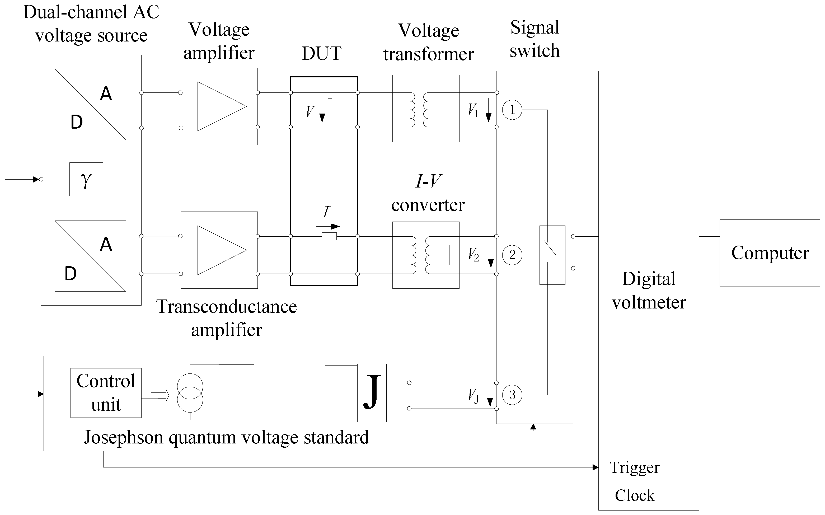
PTB developed an AC quantum power standard operating as a standard meter [84], with its schematic illustrated in Figure 12. A dual-channel digital AC voltage source generates two voltage signals. One voltage signal is amplified by a voltage amplifier and applied to the Device Under Test (DUT), while the other drives a transconductance amplifier to generate the current flowing through the DUT. The amplified voltage V is scaled down to V 1 by a voltage transformer, and the generated current is converted to a voltage signal V 2 by an I-V converter (comprising a current transformer and a shunt resistor). The nominal values of these two scaled-down voltages, V 1 and V 2 , are 8.5 V and 1.5 V, respectively. They are connected via a switch to a single sampling voltmeter for measurement.
The measurement uncertainty of the power standard is dominated by the measurement stability of the digital voltmeter. To achieve quantum accuracy, a PJVS is integrated into the system, as shown in Figure 12, enabling frequent on-site calibration of the digital voltmeter (DVM). This ensures superior short-term measurement accuracy for the DVM, thereby improving the overall accuracy of the AC power standard. For practical implementation, the PJVS generates a quantum-referenced DC voltage, which is sampled by the DVM to yield the sampled values V DVM . The corresponding ideal quantum voltage step value at each sampling instant is given by V Jos = ± N j f / K J , where N j is the number of biased Josephson junctions, f is the microwave frequency, and K J is the Josephson constant. A linear least-squares fit is applied to the data pairs ( V DVM , V Jos ) to determine the parameters in the following relationship:
V Jos = A + G · V DVM
Once the offset A and gain G are determined, any subsequent measured value V DVM obtained with the DVM can be corrected to the accurate voltage value V Jos using Equation (7).
Representing the third generation of AC power standards at PTB, following two prior generations of conventional setups, this quantum-enhanced power standard incorporates either a 1.2 V or a 10 V PJVS. The on-site calibration of the DVM reduces the measurement uncertainty for AC voltage to 0.38 μV/V ( k = 1 ). Under measurement conditions of 120 V, 5 A, and (45∼65) Hz, the achieved measurement uncertainty for the AC power standard is better than 1.1 μW/VA ( k = 1 ).
The NIM of China has established a power-frequency AC quantum power standard as a power standard meter [85]. This design incorporates the differential sampling technique from NIST’s approach into the PTB framework, allowing direct measurement of voltage and current signals. By eliminating the conventional step of pre-calibrating the sampling voltmeter with a PJVS quantum voltage signal, the process is significantly simplified and calibration efficiency is improved. The measured uncertainty of the standard is 9.4 μW/VA (k = 2) at unity power factor and 9.8 μW/VA (k = 2) at a power factor of 0.5 (lagging or leading).

5.2. Application in Mass Realization via Kibble/Joule Balance

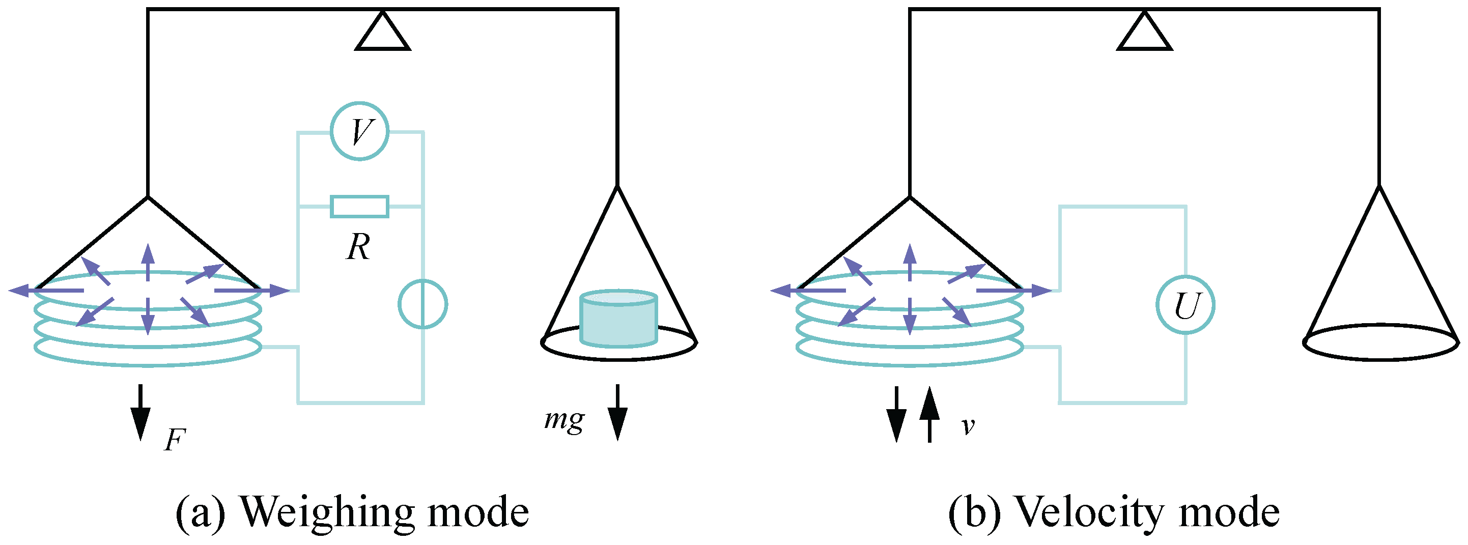
Quantum voltage standards are also employed in mass realization experiments based on the Kibble/Joule balance principle. The fundamental principle of the Kibble balance experiment was first proposed by Dr. B.P. Kibble of the National Physical Laboratory (NPL) of the United Kingdom in 1976 [86]. As shown in Figure 13, the experiment consists of two independent measurement phases, i.e., the weighing mode and the velocity mode.
In the weighing mode, a current I flowing through a coil placed in a magnetic field with a flux density B generates a vertical force. This force is balanced against the gravitational force of the measured mass m, satisfying the equation:
I ϕ z = m g
where ϕ / z is the derivative of the magnetic flux linked to the coil with respect to vertical displacement, and g is the local gravitational acceleration.
In the velocity mode, the coil is moved vertically with a constant velocity v while no current is applied. The induced voltage U in the coil is then given by
U = v ϕ z .
By eliminating the common geometric factor ϕ / z from Equations (8) and (9), the following relationship is obtained:
U I = m g v .
Equation (10) demonstrates that the Kibble balance experiment establishes a direct comparison between electrical power ( U I ) and mechanical power ( m g v ). The current I in Equation (10) can be determined by measuring the voltage V across a sampling resistor R (i.e., I = V / R ), where the resistance R itself can be determined via a calculable capacitor and a resistance bridge. The electrical power V U / R , as calibrated by the mechanical power m g v , yields an absolute determination of the voltage U (given R), and subsequently the current I via Ohm’s law. In essence, determining the SI units of voltage and current through the Kibble balance experiment is also equivalent to a precise measurement of the Planck constant h and the elementary charge e [86].
The voltages U and V can be expressed in terms of Josephson voltage standards, and the resistance R in terms of the quantum Hall resistance:
U = n 1 f 1 / K J , V = n 2 f 2 / K J , R = γ R K
where f 1 , f 2 are microwave frequencies, n 1 , n 2 are the step numbers of the Josephson junctions, K J is the Josephson constant, γ is a scaling factor accurately determined by resistance bridges, and R K is the von Klitzing constant. Substituting Equation (11) into Equation (10) leads to an expression for the Planck constant:
h = 4 K J 2 R K · m g v γ n 1 n 2 f 1 f 2 .
All quantities on the right-hand side of Equation (12) can be measured accurately, enabling a precise determination of h. The Kibble balance achieves a relative uncertainty in measuring h on the order of 10 8 . Since the quantized Hall resistance combined with a calculable capacitor determines the value of h / e 2 , and the Kibble balance determines h, the values of the elementary charge e and the Avogadro constant N A can be derived [9].
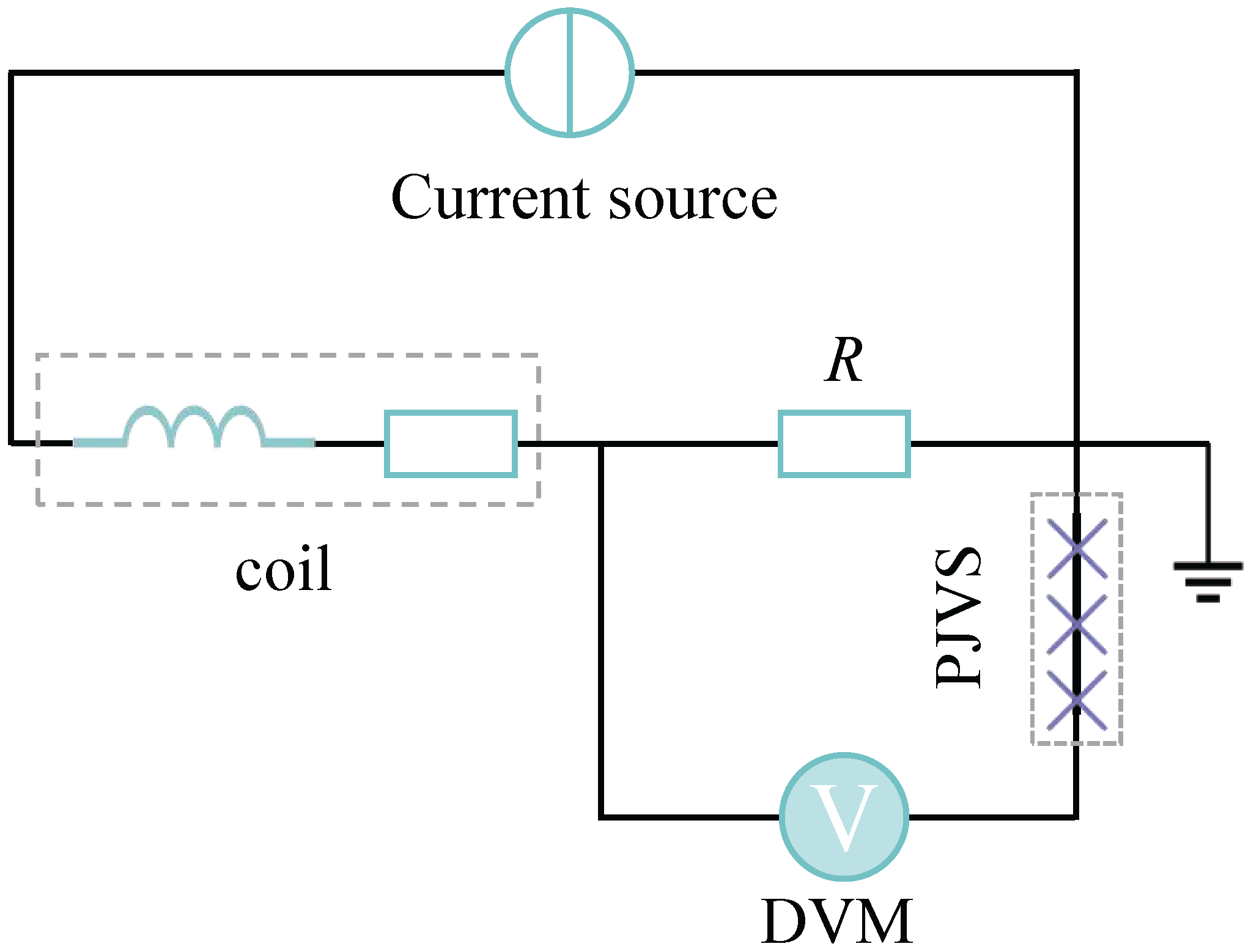
In the Kibble balance experiment, it is essential to accurately measure the voltage U across the sampling resistor and the induced voltage V. Two main approaches are currently employed. The first method uses the quantum voltage standard to periodically calibrate a DVM, ensuring its short-term accuracy during the measurement window. The second method combines the quantum voltage standard with differential sampling to achieve real-time, high-accuracy measurements. Figure 14 illustrates the quantum measurement principle for the voltage U across the resistor in the weighing mode. Under force-equilibrium conditions, the voltage across the resistor is a quasi-DC voltage signal. This signal is approximated using a DC quantum voltage signal generated by a PJVS. The differential voltage between them is then measured using a DVM, thereby achieving high-accuracy measurement of the voltage U.
The NIM of China developed the Joule balance based on the equivalence between mechanical and electrical energy [87]. In a static (or quasi-static) experiment, the mechanical work (gravitational potential energy change) from lifting a coil in a magnetic field is equated to the electrical energy measured precisely across the coil using the quantum Hall resistance and Josephson voltage standards. While the Kibble balance measures “how fast work is done”, the Joule balance measures “how much work is done”. Consequently, the Josephson quantum voltage standard is also indispensable for the high-accuracy realization of the unit of mass, the kilogram, using Joule balances.

5.3. Quantum Voltage-Calibrated Noise Thermometry

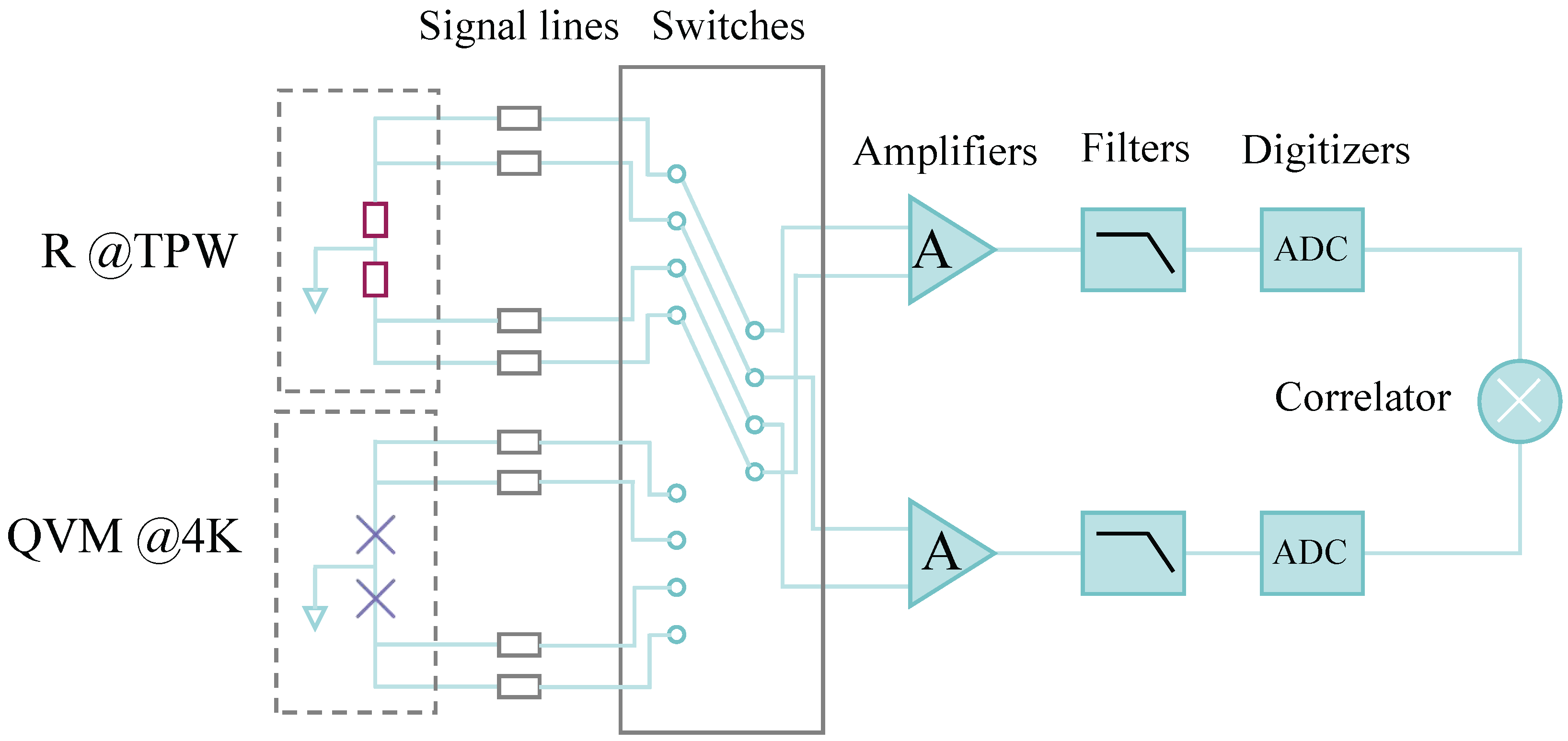
A quantum voltage-calibrated noise thermometer has been proposed as a new method for determining the Boltzmann constant, and the measurement schematic is shown in Figure 15. The primary components include a resistive thermal noise source, a quantum voltage noise source, transmission lines, a switching unit, and a two-channel cross-correlator [88,89]. The cross-correlator itself comprises amplifiers, low-pass filters, ADCs, and a DSP unit for computing the cross-correlation.
Consider a resistor with a value of R TPW maintained at the temperature T TPW of the triple point of water (TPW) fixed point. Its mean available thermal noise power within a bandwidth B is given by P th = k B T TPW B , where k B is the Boltzmann constant. The corresponding single-sided power spectral density (PSD) of the thermal noise voltage is white (frequency-independent):
S R = 4 k B T TPW R TPW .
The noise thermometer employs a quantum voltage noise source, containing multiple discrete frequency components, to calibrate the resistor’s thermal noise. To match their power levels, the PSD of the quantum voltage noise, S Q , is set to be comparable to S R . A key distinction lies in their spectral distribution. The power of the quantum voltage noise is concentrated at its discrete spectral lines, whereas the thermal noise power is distributed continuously across the frequency band.
The two-channel cross-correlator alternately measures the thermal noise and the quantum voltage noise via the switching unit. This alternating measurement scheme is crucial for rejecting the common drift and low-frequency fluctuations in the gain and frequency response of the amplifiers, filters, and ADCs. From these measurements, the Boltzmann constant can be derived as:
k B = S R 4 T TPW R TPW = S R m S Q m · S Q 4 T TPW R TPW .
where S R m and S Q m are the measured PSDs of the resistor’s thermal noise and the quantum voltage noise, respectively, as obtained by the cross-correlator. S Q is the theoretical PSD of the synthesized quantum voltage noise generated by JAWS, the accuracy of which is fundamentally determined by the AC Josephson effect. Therefore, the accurate measurement of the PSD ratio S R m / S Q m is the critical step in determining the Boltzmann constant k B .
The relative uncertainty in the measurement of the Boltzmann constant using the quantum voltage-calibrated noise thermometer has been reduced to as low as 2.7 × 10 6 , providing crucial support for the revision of the internationally recommended value of the Boltzmann constant [89]. As can be seen from Equation (14), when the Boltzmann constant is a precisely known value, the temperature can in turn be measured. Since JAWS can flexibly generate the required precise reference voltage signals, quantum voltage-calibrated noise thermometers can achieve millikelvin-level measurement accuracy over a wide temperature range and are expected to play an important role in fundamental scientific research and industrial applications [88].

5.4. Calibration of Advanced Metrology Standards

Quantum voltage standards are widely applied for the calibration of advanced metrology standards, including high-precision ADCs, lock-in amplifiers, impedance standards, and standard voltage sources [89,90].
For example, in [91], a JAWS capable of flexibly generating highly accurate AC and DC voltages is used to evaluate the AC-DC difference of a transfer standard. Instead of following the conventional method, which involves adjusting the DC voltage to match the output response of an AC input, this approach directly compares the output responses produced by precision DC and AC voltages with equal RMS values. This not only simplifies the procedure but also substantially reduces the measurement uncertainty in the AC-DC difference evaluation. In [92], PTB employed two JAWS to construct a digital impedance bridge, tracing a 10 nF capacitance back to the AC quantum Hall resistance and achieving a measurement uncertainty of 10 8 at 1233 Hz. In [93], a PJVS is used to evaluate the noise performance, stability, and linearity of a metrology-grade ADC. The assessment of these parameters provides crucial support for establishing a high-precision measurement signal chain for magnet currents in particle accelerators. Furthermore, as described in [94], a JAWS combined with differential sampling is applied to evaluate the long-term stability of an AC voltage source. Results show that the long-term stability of this voltage transfer standard is better than 4 μV/V per year.
By providing highly accurate and stable voltage references, quantum voltage standards significantly enhance the precision, traceability efficiency, and applicability of electrical metrology. They offer indispensable support for scientific experiments, such as those in particle accelerators, industrial testing, and the advancement of national measurement systems.

6. Discussion

The present status of Josephson voltage standards reveals a clear distinction between mature DC voltage realization and the still-developing quantum traceability of complex dynamic signals. The CJVS has become a well-established DC voltage reference and has been deployed in many national metrology systems. The PJVS further extends Josephson-based standards from static-voltage realization to AC-voltage measurement by synthesizing quantized staircase waveforms that can serve as quantum reference voltages in differential-sampling systems. At present, PJVS-based quantum voltmeters have achieved uncertainties on the order of 10 8 for AC voltage measurements up to 1 kHz, while coherent subsampling techniques have extended the effective measurement bandwidth to 100 kHz, with uncertainties at the 10 6 level. These achievements demonstrate that Josephson-based AC voltage metrology has reached a high level of maturity for single-frequency or narrowband steady-state signals.
However, this maturity should not be interpreted as a complete solution for dynamic electrical metrology. Existing PJVS-based measurement schemes are still largely optimized for periodic, coherent, and spectrally simple waveforms. Their performance relies critically on synchronization accuracy, sampler linearity, aperture uncertainty, phase stability, bandwidth characterization, and the validity of steady-state signal assumptions. These requirements become increasingly difficult to satisfy when the target signal is broadband, time-varying, or non-stationary. In practical power systems and power-electronic applications, voltage and current waveforms often contain harmonics, interharmonics, switching-frequency components, transient disturbances, time-varying amplitudes, phase jumps, and frequency deviations. For such signals, conventional uncertainty descriptions based only on RMS value, amplitude, or phase at a single frequency are insufficient. A more complete quantum metrology framework must address waveform-level uncertainty, time–frequency traceability, bandwidth-dependent errors, synchronization between voltage and current channels, and the propagation of these effects into power and energy quantities.
Cryogenic implementation remains another important bottleneck. The JVS is fundamentally based on the Josephson effect in superconducting junctions, and practical systems currently operate near 4.2 K using liquid helium or cryocoolers. The transition from consumable liquid helium to cryocooler-based systems has improved practicality and reduced dependence on scarce cryogenic fluids. Nevertheless, cryocooler-based systems still involve non-negligible cost, volume, and power consumption. Therefore, the realistic short-term priority is not merely to “miniaturize” the cryogenic system, but to improve its robustness, automation, thermal stability, and compatibility with deployable metrological instruments. In the longer term, high-temperature superconducting Josephson junction arrays operating near liquid nitrogen temperature may offer a transformative route toward more compact and accessible quantum voltage standards [95,96]. However, this route remains technically demanding. Junction uniformity, array yield, microwave distribution, long-term stability, reproducibility, and uncertainty evaluation must be demonstrated at a level comparable to low-temperature superconducting Josephson standards before high-temperature implementations can become a practical replacement.
For broadband and dynamic applications, the key research challenge is the gap between quantum-accurate waveform generation and quantum-accurate waveform measurement. JAWS has shown remarkable potential for synthesizing arbitrary waveforms over a very broad frequency range, from DC to the GHz regime. This capability makes it an important candidate for generating quantum-accurate references for complex dynamic signals. The corresponding high-precision measurement methodology is still less mature. In particular, the use of JAWS for metrological characterization of non-sinusoidal, modulated, transient, or power-electronic waveforms requires not only waveform synthesis, but also calibrated broadband sampling, precise timing, impedance and bandwidth correction, signal reconstruction algorithms, and rigorous uncertainty models. To date, only preliminary quantum measurement results have been reported for steady-state signals containing a limited number of frequency components [97]. A general theoretical and technical framework for quantum measurement of complex dynamic voltage signals has not yet been established.
Accordingly, the most realistic short- to medium-term research priorities are threefold. First, PJVS-based quantum voltmeters should be further developed to handle wider-band steady-state and quasi-steady-state signals, with improved uncertainty models that explicitly account for sampling, synchronization, phase, and bandwidth effects. Second, JAWS-based systems should advance from quantum waveform synthesis toward closed-loop quantum measurement and comparison, especially for non-sinusoidal and multi-frequency signals. Third, quantum traceability methods should be extended beyond voltage alone to include synchronized voltage–current–power measurements under broadband and non-stationary conditions. This is particularly important for modern power systems, which are dominated by renewable energy integration, converter-interfaced equipment, and power-electronic loads. In these scenarios, the central metrological problem is no longer only the realization of an accurate voltage value, but the establishment of a traceable, uncertainty-quantified description of complex electrical waveforms and their derived power and energy quantities.

7. Conclusions

The Josephson quantum voltage standard represents a paradigm shift in electrical metrology, decisively moving from artifact-dependent preservation to quantum-based reproduction using fundamental constants. This evolution has endowed the voltage standard with exceptional accuracy and long-term stability, establishing it as a cornerstone for realizing the SI and ensuring global measurement coherence. This review has systematically traced its underlying physics, technological progression, and expanding applications, charting its journey from a fundamental discovery to a pillar of modern precision measurement.
From a technological standpoint, the Josephson effect gives rise to three mature and complementary systems. The CJVS functions as the cornerstone for national DC voltage references. The PJVS allows for programmable quantum voltage outputs, while the JAWS enables the synthesis of quantum-accurate arbitrary and RF waveforms. Extensive international comparisons have verified their high metrological consistency, thereby underpinning a robust foundation for worldwide voltage measurement.
Beyond its primary function, the Josephson quantum voltage standard has become a key enabling technology, driving advances across diverse scientific and metrological frontiers. It is central to establishing quantum-based power and energy standards and to the precise determination of mass and the Planck constant via Kibble/Joule balances. It also supplies the essential quantum reference for redetermining the Boltzmann constant via noise thermometry, and provides the ultimate traceable standard for calibrating high-accuracy metrology instruments, thereby reinforcing the integrity of the entire measurement chain, from fundamental research to industrial application.
Looking ahead, the Josephson quantum voltage standard is evolving toward greater practicality and integration. Future progress hinges on enhancing system accessibility and capability, particularly through the development of high-temperature superconducting technologies. A key frontier lies in creating new quantum-based measurement methods capable of characterizing complex, dynamic signals. The convergence of programmable accuracy, waveform synthesis flexibility, and advanced signal processing is paving the way for a new quantum metrology paradigm. Ultimately, as a foundational component within a broader ecosystem of quantum electrical standards, it will underpin a robust, universal measurement system essential for future scientific and technological advancement.

Author Contributions

Conceptualization, X.L. and S.L.; methodology, S.Q. and J.L.; formal analysis, S.Q. and J.L.; investigation, L.Z. and F.P.; writing—original draft preparation, X.L., S.L., Y.J. and Y.Y.; writing—review and editing, L.F. All authors have read and agreed to the published version of the manuscript.

Funding

This research was funded by the science and technology project of China Southern Power Grid, Ltd. (GDKJXM20230982).

Data Availability Statement

Data are contained within the article.

Acknowledgments

The authors acknowledge support from the science and technology project of China Southern Power Grid, Ltd. (GDKJXM20230982).

Conflicts of Interest

The authors Lihua Zhong, Shuzhe Qi, Jinli Li, Feng Pan, Yilin Ji, Yuyao Yang, and Lei Feng were employed by Power Measurement Center, Guangdong Power Grid Co., Ltd. The remaining authors declare that the research was conducted in the absence of any commercial or financial relationships that could be construed as a potential conflict of interest. The authors declare that this study received funding from support from the science and technology project of China Southern Power Grid, Ltd. (GDKJXM20230982). The funder had the following involvement with the study: methodology, formal analysis, investigation, writing—original draft preparation, and writing—review and editing.

References

  1. Boulabiar, A.; Bouraoui, K.; Chastrette, M.; Abderrabba, M. A historical analysis of the Daniell cell and electrochemistry teaching in French and Tunisian textbooks. J. Chem. Educ. 2004, 81, 754–757. [Google Scholar] [CrossRef] [Scilit]
  2. Bender, D.; Schlesok, W. Neue Aspekte bei der Absolutbestimmung des Ampere mit der Stromwaage. Metrologia 1974, 10, 1. [Google Scholar] [CrossRef] [Scilit]
  3. Thompson, A.M.; Lampard, D.G. A new theorem in electrostatics and its application to calculable standards of capacitance. Nature 1956, 177, 888. [Google Scholar] [CrossRef] [Scilit]
  4. Sienknecht, V.; Funck, T. Realization of the SI unit volt by means of a voltage balance. Metrologia 1986, 22, 209–212. [Google Scholar] [CrossRef] [Scilit]
  5. Hamer, W.J. Standard Cells: Their Construction, Maintenance, and Characteristics; National Bureau of Standards Monograph 84; National Bureau of Standards: Washington, DC, USA, 1965. [Google Scholar] [CrossRef] [Scilit]
  6. Bülau, A.; Walter, D.; Zimmermann, A. A 10 V transfer standard based on low-noise solid-state Zener voltage reference ADR1000. Metrology 2024, 4, 98–116. [Google Scholar] [CrossRef] [Scilit]
  7. Josephson, B.D. Possible new effects in superconductive tunnelling. Phys. Lett. 1962, 1, 251–253. [Google Scholar] [CrossRef] [Scilit]
  8. Taylor, B.N.; Witt, T.J. New international electrical reference standards based on the Josephson and quantum Hall effects. Metrologia 1989, 26, 47–62. [Google Scholar] [CrossRef] [Scilit]
  9. Tiesinga, E.; Mohr, P.J.; Newell, D.B.; Taylor, B.N. CODATA recommended values of the fundamental physical constants: 2018. J. Phys. Chem. Ref. Data 2021, 50, 033105. [Google Scholar] [CrossRef]
  10. Hamilton, C.A. Josephson voltage standards. Rev. Sci. Instrum. 2000, 71, 3611–3623. [Google Scholar] [CrossRef] [Scilit]
  11. Kaneko, N.; Maruyama, M.; Urano, C.; Kiryu, S. Review of Josephson waveform synthesis and possibility of new operation method by multibit delta–sigma modulation and thermometer code for its further advancement. Jpn. J. Appl. Phys. 2012, 51, 010116. [Google Scholar] [CrossRef] [Scilit]
  12. Anderson, P.W.; Rowell, J.M. Probable observation of the Josephson superconducting tunneling effect. Phys. Rev. Lett. 1963, 10, 230–232. [Google Scholar] [CrossRef] [Scilit]
  13. Shapiro, S. Josephson currents in superconducting tunneling: The effect of microwaves and other observations. Phys. Rev. Lett. 1963, 11, 80–82. [Google Scholar] [CrossRef] [Scilit]
  14. National Institute of Standards and Technology (NIST). History of NIST Quantum Voltage Standards. Available online: https://www.nist.gov/pml/history-nist-quantum-voltage-standards (accessed on 8 May 2026).
  15. Field, B.F.; Finnegan, T.F.; Toots, J. Volt maintenance at NBS via 2e/h: A new definition of the NBS volt. Metrologia 1973, 9, 155–166. [Google Scholar] [CrossRef] [Scilit]
  16. Niemeyer, J.; Hinken, J.H.; Kautz, R.L. Microwave-induced constant-voltage steps at one volt from a series array of Josephson junctions. Appl. Phys. Lett. 1984, 45, 478–480. [Google Scholar] [CrossRef] [Scilit]
  17. Hamilton, C.A.; Kautz, R.L.; Steiner, R.L.; Lloyd, F.L. A practical Josephson voltage standard at 1 V. IEEE Electron Device Lett. 1985, 6, 623–625. [Google Scholar] [CrossRef] [Scilit]
  18. Lloyd, F.L.; Hamilton, C.A.; Beall, J.A.; Go, D.; Ono, R.H.; Harris, R.E. A Josephson array voltage standard at 10 V. IEEE Electron Device Lett. 1987, 8, 449–450. [Google Scholar] [CrossRef] [Scilit]
  19. Hamilton, C.A.; Lloyd, F.L.; Chieh, K.; Goeke, W.C. A 10-V Josephson voltage standard. IEEE Trans. Instrum. Meas. 1989, 38, 314–316. [Google Scholar] [CrossRef] [Scilit]
  20. Hamilton, C.A.; Burroughs, C.; Chieh, K. Operation of NIST Josephson array voltage standards. J. Res. Natl. Inst. Stand. Technol. 1990, 95, 219–235. [Google Scholar] [CrossRef] [Scilit] [PubMed]
  21. Solve, S.; Stock, M. BIPM direct on-site Josephson voltage standard comparisons: 20 years of results. Meas. Sci. Technol. 2012, 23, 124001. [Google Scholar] [CrossRef] [Scilit]
  22. Hamilton, C.A.; Burroughs, C.J.; Kautz, R.L. Josephson D/A converter with fundamental accuracy. IEEE Trans. Instrum. Meas. 1995, 44, 223–225. [Google Scholar] [CrossRef] [Scilit]
  23. Benz, S.P.; Hamilton, C.A.; Burroughs, C.J.; Harvey, T.E.; Christian, L.A. Stable 1 volt programmable voltage standard. Appl. Phys. Lett. 1997, 71, 1866–1868. [Google Scholar] [CrossRef] [Scilit]
  24. Chong, Y.; Burroughs, C.J.; Dresselhaus, P.D.; Hadacek, N.; Yamamori, H.; Benz, S.P. 2.6-V high-resolution programmable Josephson voltage standard circuits using double-stacked MoSi2-barrier junctions. IEEE Trans. Instrum. Meas. 2005, 54, 616–619. [Google Scholar] [CrossRef]
  25. Durandetto, P.; Sosso, A. Non-conventional PJVS exploiting first and second steps to reduce junctions and bias lines. IEEE Trans. Instrum. Meas. 2020, 69, 1294–1301. [Google Scholar] [CrossRef] [Scilit]
  26. Dresselhaus, P.D.; Benz, S.P.; Burroughs, C.J.; Bergren, N.F.; Chong, Y. Design of SNS Josephson arrays for high voltage applications. IEEE Trans. Appl. Supercond. 2007, 17, 173–176. [Google Scholar] [CrossRef] [Scilit]
  27. Urano, C.; Murayama, Y.; Iwasa, A.; Shoji, A.; Yamamori, H.; Ishizaki, M. A precise evaluation of NbN-based 1-V programmable Josephson voltage standard arrays. IEEE Trans. Instrum. Meas. 2005, 54, 645–648. [Google Scholar] [CrossRef]
  28. Matsumaru, D.; Nakamura, S.; Maruyama, M.; Kaneko, N.-H. Stable voltage generation with a Josephson voltage standard device cooled at a 4 K stage in a dilution refrigerator. IEEE Trans. Instrum. Meas. 2023, 72, 1004706. [Google Scholar] [CrossRef] [Scilit]
  29. Rüfenacht, A.; Howe, L.A.; Fox, A.E.; Schwall, R.E.; Dresselhaus, P.D.; Burroughs, C.J.; Benz, S.P. Cryocooled 10 V programmable Josephson voltage standard. IEEE Trans. Instrum. Meas. 2015, 64, 1477–1482. [Google Scholar] [CrossRef] [Scilit]
  30. Wang, Z.; Gao, Y.; Li, H. Binary AC Josephson system and bias current circuits at NIM. In Proceedings of the 2012 Conference on Precision Electromagnetic Measurements (CPEM), Washington, DC, USA, 1–6 July 2012; pp. 680–681. [Google Scholar] [CrossRef] [Scilit]
  31. Malétras, F.X.; Gournay, P.; Robinson, I.A.; Genevès, G. A bias source for dynamic voltage measurements with a programmable Josephson junction array. IEEE Trans. Instrum. Meas. 2007, 56, 495–499. [Google Scholar] [CrossRef] [Scilit]
  32. Kieler, O.; Behr, R.; Müller, F.; Schulze, H.; Kohlmann, J.; Niemeyer, J. Improved 1 V programmable Josephson voltage standard using SINIS junctions. Physica C 2002, 372–376, 309–311. [Google Scholar] [CrossRef] [Scilit]
  33. Mueller, F.; Behr, R.; Weimann, T.; Palafox, L.; Olaya, D.; Dresselhaus, P.D.; Benz, S.P. 1 V and 10 V SNS programmable voltage standards for 70 GHz. IEEE Trans. Appl. Supercond. 2009, 19, 981–986. [Google Scholar] [CrossRef]
  34. Yamamori, H.; Ishizaki, M.; Shoji, A.; Dresselhaus, P.D.; Benz, S.P. 10 V programmable Josephson voltage standard circuits using NbN/TiNx/NbN/TiNx/NbN double-junction stacks. Appl. Phys. Lett. 2006, 88, 042503. [Google Scholar] [CrossRef] [Scilit]
  35. Dresselhaus, P.D.; Elsbury, M.M.; Olaya, D.; Burroughs, C.J.; Benz, S.P. 10 volt programmable Josephson voltage standard circuits using NbSi-barrier junctions. IEEE Trans. Appl. Supercond. 2011, 21, 693–696. [Google Scholar] [CrossRef] [Scilit]
  36. Elsbury, M.M.; Dresselhaus, P.D.; Bergren, N.F.; Burroughs, C.J.; Benz, S.P.; Popović, Z. Broadband lumped-element integrated N-way power dividers for voltage standards. IEEE Trans. Microw. Theory Tech. 2009, 57, 2055–2063. [Google Scholar] [CrossRef]
  37. Chong, Y.; Burroughs, C.J.; Dresselhaus, P.D.; Hadacek, N.; Yamamori, H.; Benz, S.P. Practical high-resolution programmable Josephson voltage standards using double- and triple-stacked MoSi2-barrier junctions. IEEE Trans. Appl. Supercond. 2005, 15, 461–464. [Google Scholar] [CrossRef]
  38. Müller, F.; Scheller, T.; Wendisch, R.; Behr, R.; Kieler, O.; Palafox, L.; Kohlmann, J. NbSi barrier junctions tuned for metrological applications up to 70 GHz: 20 V arrays for programmable Josephson voltage standards. IEEE Trans. Appl. Supercond. 2013, 23, 1101005. [Google Scholar] [CrossRef] [Scilit]
  39. Yamamori, H.; Yamada, T.; Sasaki, H.; Shoji, A. A 10 V programmable Josephson voltage standard circuit with a maximum output voltage of 20 V. Supercond. Sci. Technol. 2008, 21, 105007. [Google Scholar] [CrossRef] [Scilit]
  40. Yamamori, H.; Kohjiro, S. Fabrication of voltage standard circuits utilizing a serial-parallel power divider. IEEE Trans. Appl. Supercond. 2016, 26, 1400404. [Google Scholar] [CrossRef]
  41. Lacquaniti, V.; De Leo, N.; Fretto, M.; Sosso, A.; Müller, F.; Kohlmann, J. 1 V programmable voltage standards based on SNIS Josephson junction series arrays. Supercond. Sci. Technol. 2011, 24, 045004. [Google Scholar] [CrossRef] [Scilit]
  42. Klushin, A.M.; Pestov, E.E.; Galin, M.A.; Levichev, M.Y. High-temperature superconductor Josephson junctions for voltage standards. Phys. Solid State 2016, 58, 2196–2202. [Google Scholar] [CrossRef] [Scilit]
  43. National Institute of Standards and Technology (NIST). SRI 6000 Series Programmable Josephson Voltage Standard (PJVS). Available online: https://www.nist.gov/sri/standard-reference-instruments/sri-6000-series-programmable-josephson-voltage-standard-pjvs (accessed on 8 May 2026).
  44. Supracon AG. Quantum Voltmeter. Available online: https://supracon.de/quantenmetrologie/quantenvoltmeter (accessed on 8 May 2026).
  45. Wang, Z.; Gao, Y.; Li, H.; Yan, Y. Research on differential sampling method with 10 Volt programmable Josephson voltage standard at NIM. In Proceedings of the 2015 12th IEEE International Conference on Electronic Measurement & Instruments (ICEMI), Qingdao, China, 16–18 July 2015; Volume 2, pp. 703–707. [Google Scholar] [CrossRef] [Scilit]
  46. Wang, L.; Li, J.; Cao, W.; Zhong, Y.; Zhang, Z. Development of 0.5-V Josephson junction array devices for quantum voltage standards. Chin. Phys. B 2019, 28, 068501. [Google Scholar] [CrossRef] [Scilit]
  47. Cao, W.; Li, J.; Zhong, Y.; Zhong, Q.; Xu, D.; Wang, X.; Xu, X. Realization of a 2-V Programmable Josephson Junction Array Using Balanced Segmentation Scheme. IEEE Trans. Appl. Supercon. 2022, 32, 1301805. [Google Scholar] [CrossRef] [Scilit]
  48. Benz, S.P.; Hamilton, C.A. A pulse-driven programmable Josephson voltage standard. Appl. Phys. Lett. 1996, 68, 3171–3173. [Google Scholar] [CrossRef] [Scilit]
  49. Kieler, O.F.; Behr, R.; Wendisch, R.; Bauer, S.; Palafox, L.; Kohlmann, J. Towards a 1 V Josephson arbitrary waveform synthesizer. IEEE Trans. Appl. Supercond. 2015, 25, 1400305. [Google Scholar] [CrossRef] [Scilit]
  50. Benz, S.P.; Burroughs, C.J.; Harvey, T.E.; Hamilton, C.A. Operating conditions for a pulse-quantized AC and DC bipolar voltage source. IEEE Trans. Appl. Supercond. 1999, 9, 3306–3309. [Google Scholar] [CrossRef] [Scilit]
  51. Flowers-Jacobs, N.E.; Fox, A.E.; Dresselhaus, P.D.; Schwall, R.E.; Benz, S.P. Two-Volt Josephson arbitrary waveform synthesizer using Wilkinson dividers. IEEE Trans. Appl. Supercond. 2016, 26, 1400207. [Google Scholar] [CrossRef] [Scilit] [PubMed]
  52. Kieler, O.; Wendisch, R.; Gerdau, R.-W.; Weimann, T.; Kohlmann, J.; Behr, R. Stacked Josephson junction arrays for the pulse-driven AC Josephson voltage standard. IEEE Trans. Appl. Supercond. 2021, 31, 1100705. [Google Scholar] [CrossRef] [Scilit]
  53. Benz, S.P.; Waltman, S.B.; Fox, A.E.; Dresselhaus, P.D.; Rüfenacht, A.; Howe, L.A.; Schwall, R.E.; Flowers-Jacobs, N.E. Performance improvements for the NIST 1 V Josephson arbitrary waveform synthesizer. IEEE Trans. Appl. Supercond. 2015, 25, 1400105. [Google Scholar] [CrossRef] [Scilit]
  54. Flowers-Jacobs, N.E.; Waltman, S.B.; Fox, A.E.; Dresselhaus, P.D.; Benz, S.P. Josephson arbitrary waveform synthesizer with two layers of Wilkinson dividers and an FIR filter. IEEE Trans. Appl. Supercond. 2016, 26, 1400307. [Google Scholar] [CrossRef] [Scilit]
  55. Benz, S.P.; Burroughs, C.J.; Dresselhaus, P.D. AC coupling technique for Josephson waveform synthesis. IEEE Trans. Appl. Supercond. 2001, 11, 612–616. [Google Scholar] [CrossRef] [Scilit]
  56. Zhou, K.; Qu, J.; Benz, S.P. Zero-compensation method and reduced inductive voltage error for the AC Josephson voltage standard. IEEE Trans. Appl. Supercond. 2015, 25, 1400806. [Google Scholar] [CrossRef] [Scilit]
  57. Benz, S.P.; Waltman, S.B. Pulse-bias electronics and techniques for a Josephson arbitrary waveform synthesizer. IEEE Trans. Appl. Supercond. 2014, 24, 1400107. [Google Scholar] [CrossRef] [Scilit]
  58. Donnelly, C.A.; Flowers-Jacobs, N.E.; Brevik, J.A.; Fox, A.E.; Dresselhaus, P.D.; Hopkins, P.F.; Benz, S.P. 1 GHz waveform synthesis with Josephson junction arrays. IEEE Trans. Appl. Supercond. 2020, 30, 1400111. [Google Scholar] [CrossRef] [Scilit] [PubMed]
  59. Thomas, J.N.; Flowers-Jacobs, N.E.; Fox, A.E.; Babenko, A.A.; Benz, S.P.; Dresselhaus, P.D. VHF Josephson arbitrary waveform synthesizer. IEEE Trans. Appl. Supercond. 2024, 34, 1500810. [Google Scholar] [CrossRef] [Scilit]
  60. Kieler, O.; Karlsen, B.; Ohlckers, P.A.; Bardalen, E.; Akram, M.N.; Behr, R.; Ireland, J.; Williams, J.; Malmbekk, H.; Palafox, L.; et al. Optical pulse-drive for the pulse-driven AC Josephson voltage standard. IEEE Trans. Appl. Supercond. 2019, 29, 1200205. [Google Scholar] [CrossRef] [Scilit]
  61. Kraus, M.; Kieler, O.; Behr, R.; Palafox, L. Parallelization of the Optical Pulse-Drive for AC Josephson Voltage Standards. Meas. Sci. Technol. 2025, 36, 095006. [Google Scholar] [CrossRef] [Scilit]
  62. National Institute of Standards and Technology (NIST). SRI 6011 Josephson Arbitrary Waveform Synthesizer. Updated 12 February 2026. Available online: https://www.nist.gov/sri/sri-6011-josephson-arbitrary-waveform-synthesizer (accessed on 8 May 2026).
  63. Zhou, K.; Qu, J.; Zhao, J.; Xu, X.; Shi, Y. Behavior modeling of the amplifier nonlinearity with the AC Josephson voltage standard. IEEE Trans. Instrum. Meas. 2019, 68, 1990–1995. [Google Scholar] [CrossRef]
  64. Jia, W.; Song, J.; Zhong, Y.; Zhou, K.; Han, Q.; Cao, W.; Li, J.; Cai, J.; Wan, J.; Zhao, Z. A 300 mV Josephson arbitrary waveform synthesizer chip at NIM. Appl. Sci. 2025, 15, 11811. [Google Scholar] [CrossRef] [Scilit]
  65. Bureau International des Poids et Mesures (BIPM). BIPM.EM-K10 Technical Protocol; BIPM: Sèvres, France, 2023. Available online: https://www.bipm.org/kcdb/comparison/doc/download/1779/BIPM.EM-K10_Technical_Protocol.pdf (accessed on 8 May 2026).
  66. Li, H.; Gao, Y.; Wang, Z. Comparison of the 10 V Josephson voltage standards of the conventional and the programmable at NIM. In Proceedings of the 2015 12th IEEE International Conference on Electronic Measurement & Instruments (ICEMI), Qingdao, China, 16–18 July 2015; pp. 713–717. [Google Scholar] [CrossRef] [Scilit]
  67. Tang, Y.; Wachter, J.; Rüfenacht, A.; FitzPatrick, G.J.; Benz, S.P. Application of a 10 V programmable Josephson voltage standard in direct comparison with conventional Josephson voltage standards. IEEE Trans. Instrum. Meas. 2015, 64, 3458–3466. [Google Scholar] [CrossRef] [Scilit]
  68. Solve, S.; Chayramy, R.; Maruyama, M.; Urano, C.; Kaneko, N.-H.; Rüfenacht, A. Direct DC 10 V comparison between two programmable Josephson voltage standards made of niobium nitride (NbN)-based and niobium (Nb)-based Josephson junctions. Metrologia 2018, 55, 302–313. [Google Scholar] [CrossRef] [Scilit]
  69. Yang, S.; Cular, S.; Rüfenacht, A.; Burroughs, C.J.; Dresselhaus, P.D.; Benz, S.P.; Ng, M.N. Direct DC voltages comparison between two programmable Josephson voltage standards at SCL. In Proceedings of the 2020 Conference on Precision Electromagnetic Measurements (CPEM), Denver, CO, USA, 24–28 August 2020; pp. 1–2. [Google Scholar] [CrossRef] [Scilit]
  70. Rüfenacht, A.; Flowers-Jacobs, N.E.; Fox, A.E.; Waltman, S.B.; Schwall, R.E.; Burroughs, C.J. DC comparison of a programmable Josephson voltage standard and a Josephson arbitrary waveform synthesizer. In Proceedings of the 2018 Conference on Precision Electromagnetic Measurements (CPEM), Paris, France, 8–13 July 2018; pp. 1–2. [Google Scholar] [CrossRef] [Scilit]
  71. Solve, S.; Chayramy, R.; Stock, M.; Behr, R.; Palafox, L. Bilateral comparison of AC programmable Josephson voltage standard (0.75 V rms and 7 V rms) between the PTB (Germany) and the BIPM, June 2025 (part of the ongoing BIPM key comparison BIPM.EM-K10.c and d). Metrologia 2025, 62, 01012. [Google Scholar] [CrossRef] [Scilit]
  72. Jeanneret, B.; Rüfenacht, A.; Overney, F.; van den Brom, H.; Houtzager, E. High precision comparison between a programmable and a pulse-driven Josephson voltage standard. Metrologia 2011, 48, 311–316. [Google Scholar] [CrossRef] [Scilit]
  73. Behr, R.; Kieler, O.; Lee, J.; Bauer, S.; Palafox, L.; Kohlmann, J. Direct comparison of a 1 V Josephson arbitrary waveform synthesizer and an AC quantum voltmeter. Metrologia 2015, 52, 528–537. [Google Scholar] [CrossRef] [Scilit]
  74. Flowers-Jacobs, N.E.; Rüfenacht, A.; Fox, A.E.; Dresselhaus, P.D.; Benz, S.P. 2 Volt pulse-driven Josephson arbitrary waveform synthesizer. In Proceedings of the 2016 Conference on Precision Electromagnetic Measurements (CPEM 2016), Ottawa, ON, Canada, 10–15 July 2016; pp. 1–2. [Google Scholar] [CrossRef] [Scilit]
  75. Han, Q.; Zhou, K.; Zhong, Y.; Lu, Q.; Chen, B.; Yang, Y.; Shi, Y.; Li, J.; Liu, J.; Sun, J.; et al. Comparison between Josephson arbitrary waveform synthesizers using a cross-correlation technique. Measurement 2026, 266, 120421. [Google Scholar] [CrossRef] [Scilit]
  76. Kraus, M.; Drung, D.; Behr, R.; Palafox, L.; Kieler, O.; Bauer, S.; Herick, J. Measurement and analysis of high-frequency voltage errors in the Josephson arbitrary waveform synthesizer. Meas. Sci. Technol. 2020, 31, 125003. [Google Scholar] [CrossRef] [Scilit]
  77. Rüfenacht, A.; Burroughs, C.J.; Benz, S.P.; Dresselhaus, P.D.; Waltrip, B.C.; Nelson, T.L. Precision differential sampling measurements of low-frequency synthesized sine waves with an AC programmable Josephson voltage standard. IEEE Trans. Instrum. Meas. 2009, 58, 809–815. [Google Scholar] [CrossRef] [Scilit]
  78. Lee, J.; Behr, R.; Palafox, L.; Katkov, A.; Schubert, M.; Starkloff, M.; Böck, A.C. An AC quantum voltmeter based on a 10 V programmable Josephson array. Metrologia 2013, 50, 612–622. [Google Scholar] [CrossRef] [Scilit]
  79. Rüfenacht, A.; Johnson, R.; Fox, A.; Flowers-Jacobs, N.; Burroughs, C.; Benz, S.; Dresselhaus, P.; Solve, S.; Mejia, J. Differential measurements of an AC source with a Josephson arbitrary waveform synthesizer. In Proceedings of the 2024 Conference on Precision Electromagnetic Measurements (CPEM), Denver, CO, USA, 8–12 July 2024; pp. 1–2. [Google Scholar] [CrossRef] [Scilit]
  80. Kürten Ihlenfeld, W.G.; Landim, R.P. Investigations on extending the frequency range of PJVS based AC voltage calibrations by coherent subsampling. In Proceedings of the 2016 Conference on Precision Electromagnetic Measurements (CPEM), Ottawa, ON, Canada, 10–15 July 2016. [Google Scholar] [CrossRef] [Scilit]
  81. Behr, R.; Palafox, L. An AC quantum voltmeter for frequencies up to 100 kHz using sub-sampling. Metrologia 2021, 58, 025010. [Google Scholar] [CrossRef] [Scilit]
  82. Waltrip, B.C.; Gong, B.; Nelson, T.L.; Wang, Y.; Burroughs, C.J.; Rüfenacht, A.; Benz, S.P.; Dresselhaus, P.D. AC power standard using a programmable Josephson voltage standard. IEEE Trans. Instrum. Meas. 2009, 58, 1041–1048. [Google Scholar] [CrossRef] [Scilit]
  83. Djokić, B.V. Low-frequency quantum-based AC power standard at NRC Canada. IEEE Trans. Instrum. Meas. 2013, 62, 1699–1703. [Google Scholar] [CrossRef] [Scilit]
  84. Palafox, L.; Ramm, G.; Behr, R.; Kürten Ihlenfeld, W.G.; Moser, H. Primary AC power standard based on programmable Josephson junction arrays. IEEE Trans. Instrum. Meas. 2007, 56, 534–537. [Google Scholar] [CrossRef] [Scilit]
  85. Jia, Z.; Wang, L.; Xu, X.; Zhou, T.; Pan, X.; Shi, Z.; Zhang, J. Research on AC power measurement system and method based on Josephson quantum voltage. Acta Metrol. Sin. 2020, 41, 469–474. [Google Scholar]
  86. Kibble, B.P. A measurement of the gyromagnetic ratio of the proton by the strong field method. In Atomic Masses and Fundamental Constants 5; Sanders, J.H., Wapstra, A.H., Eds.; Springer: Boston, MA, USA, 1976; pp. 545–551. [Google Scholar] [CrossRef] [Scilit]
  87. Wang, G.; Zhang, Z.; Lu, Y.; Xu, J.; Zhou, K. Precision square waves synthesized by programmable Josephson voltage standards for induced voltage compensation in a Joule balance. Meas. Sci. Technol. 2016, 27, 015003. [Google Scholar] [CrossRef] [Scilit]
  88. Benz, S.P.; Coakley, K.J.; Flowers-Jacobs, N.E.; Rogalla, H.; Tew, W.L.; Qu, J.; White, D.R.; Gaiser, C.; Pollarolo, A.; Urano, C. Practical realisation of the kelvin by Johnson noise thermometry. Metrologia 2024, 61, 022001. [Google Scholar] [CrossRef] [Scilit]
  89. Qu, J.F.; Benz, S.P.; Rogalla, H.; Tew, W.L.; White, D.R.; Zhou, K.L. Johnson noise thermometry. Meas. Sci. Technol. 2019, 30, 112001. [Google Scholar] [CrossRef] [Scilit]
  90. Benz, S.P.; Biesecker, J.; Burroughs, C.J.; Castellanos-Beltran, M.A.; Dresselhaus, P.D.; Flowers-Jacobs, N.E.; Fox, A.E.; Hopkins, P.F.; Johnson-Wilke, R.; Olaya, D.; et al. AC metrology applications of the Josephson effect. Appl. Phys. Lett. 2024, 125, 050501. [Google Scholar] [CrossRef] [Scilit]
  91. Kieler, O. Development of Josephson arbitrary waveform synthesizer at Physikalisch-Technische Bundesanstalt (PTB). Low Temp. Phys. 2024, 50, 948–961. [Google Scholar] [CrossRef] [Scilit]
  92. Marzano, M.; Pimsut, Y.; Kruskopf, M.; Yin, Y.; Kraus, M.; D’Elia, V.; Callegaro, L.; Ortolano, M.; Bauer, S.; Behr, R. PTB–INRIM comparison of novel digital impedance bridges with graphene impedance quantum standards. Metrologia 2022, 59, 065001. [Google Scholar] [CrossRef] [Scilit]
  93. Beev, N.; Bastos, M.C.; Martino, M.; Valuch, D.; Palafox, L.; Behr, R. Design and metrological characterization of a digitizer for the highest precision magnet powering in the high luminosity large Hadron Collider. IEEE Trans. Instrum. Meas. 2024, 73, 6501710. [Google Scholar] [CrossRef] [Scilit]
  94. Granger, G.; Kürten Ihlenfeld, W.G.; Rüfenacht, A.; Flowers-Jacobs, N.E.; Fox, A.E.; Johnson, R.L.; Mejia, J.M. Stability study of AC voltage source using Josephson voltage standards. In Proceedings of the 2024 Conference on Precision Electromagnetic Measurements (CPEM), Denver, CO, USA, 8–12 July 2024; pp. 1–2. [Google Scholar] [CrossRef] [Scilit]
  95. Khorshev, S.K.; Pashkovsky, A.I.; Subbotin, A.N.; Rogozhkina, N.V.; Gryaznov, Y.M.; Levichev, M.Y.; Pestov, E.E.; Galin, M.A.; Maksimov, V.Y.; Zhezlov, D.A.; et al. Voltage standard based on dry-cooled high-temperature superconductor Josephson junctions. IEEE Trans. Instrum. Meas. 2019, 68, 2113–2120. [Google Scholar] [CrossRef] [Scilit]
  96. Pröpper, M.; Tucholke, M.A.; Schmid, C.; Kieler, O.; Neumann, M.; Ritter, P.J.; Goldobin, E.; Koelle, D.; Kleiner, R.; Schilling, M.; et al. Toward a voltage standard using YBa2Cu3O7-x Josephson junction arrays fabricated by He-FIB. IEEE Trans. Appl. Supercond. 2026, 36, 1400106. [Google Scholar] [CrossRef] [Scilit]
  97. Luna, E.; Iuzzolino, R.; Palafox, L.; Real, M.; Behr, R. A novel method for multitone signal characterization using the AC quantum voltmeter. In Proceedings of the 2024 Conference on Precision Electromagnetic Measurements (CPEM), Denver, CO, USA, 8–12 July 2024; pp. 1–2. [Google Scholar] [CrossRef] [Scilit]
Figure 1. Schematic diagram of the Josephson junction and its operating principle.
Energies 19 02667 g001
Figure 2. I-V characteristic curves of underdamped (a) and overdamped (b) Josephson junctions.
Energies 19 02667 g002
Figure 3. An overall development timeline for CJVS.
Energies 19 02667 g003
Figure 4. Schematic diagram of a programmable quantum voltage standard with the Josephson junctions configured in a binary scheme.
Energies 19 02667 g004
Figure 5. Overall architecture of the PJVS system.
Energies 19 02667 g005
Figure 6. Quantum voltage waveform generation procedure of JAWS.
Energies 19 02667 g006
Figure 7. Intercomparison configuration among different types of Josephson voltage standards.
Energies 19 02667 g007
Figure 8. Principle of PJVS-based differential sampling measurement for AC voltage.
Energies 19 02667 g008
Figure 9. Schematic of PJVS-based differential sampling measurement system.
Energies 19 02667 g009
Figure 10. Principle of PJVS-based coherent subsampling method for high-frequency AC voltage measurement.
Energies 19 02667 g010
Figure 11. Schematic of the primary quantum power standard as a standard power source established by NIST.
Energies 19 02667 g011
Figure 12. Schematic of the primary quantum power standard as a standard power meter established by PTB.
Energies 19 02667 g012
Figure 13. Principle of the Kibble balance. (a) weighing mode, (b) velocity mode.
Energies 19 02667 g013
Figure 14. Schematic of the accurate measurement of voltage V across the sampling resistor R in a Kibble balance experiment, using a PJVS-based differential sampling method.
Energies 19 02667 g014
Figure 15. Schematic diagram of the quantum voltage-calibrated noise thermometry.
Energies 19 02667 g015
Table 1. Comparative analysis of Josephson voltage standard technologies: CJVS, PJVS, and JAWS.
FeatureCJVSPJVSJAWS
PrincipleConstant voltage steps driven by RFBinary array driven by RF and DC biasPulsed synthesis of arbitrary waveforms
Voltage≤10 V≤10 V≤4 V
FrequencyDCDC 1   kHz DC ∼ MHz
Uncertainty ( k = 1 ) 10 10 10 10 10 8 10 10 10 6
ComplexityLowHighVery High
CryogenicsLiquid heliumLiquid helium or cryocoolerLiquid helium or cryocooler
AutomationLowHighHigh
MaturityMature (primary standard)Mature (widely used)Relatively mature (toward standardized applications)
Main ApplicationsNational DC voltage standard, key comparisonsAC voltage calibration, quantum AC standardCalibration of broadband characteristics for metrological devices
Key AdvantagesHighest accuracy & stabilityHigh accuracy & programmabilityHigh accuracy & arbitrary waveform capability
Major LimitationsDiscrete fixed outputsStepwise waveforms, uncertainty rises with frequencyLow amplitude, high system complexity
Table 2. Comparison results of different voltage types and methods with the coverage factor k = 1 .
Comparison TypeComparison MethodComparison Results
DC to DC voltageDirect comparisonFor DC 10 V:
( 1.8 ± 4 ) × 10 10 [66], ( 0.4 ± 2.33 ) × 10 10 [67],
( 0.05 ± 0.79 ) × 10 10 [68], ( 0.5 ± 1.1 ) × 10 10 [69]
Staircase to staircase voltage waveformIndirect comparisonFor 0.75   V ( RMS ) :
( 1 ± 2.5 ) × 10 8   @   62.5   Hz ,
( 3.7 ± 1.7 ) × 10 8   @   1   kHz ,
For 7   V ( RMS ) :
( 2.6 ± 2.7 ) × 10 8   @   62.5   Hz ,
( 2.4 ± 3.3 ) × 10 8   @   1   kHz [71]
Staircase to sine waveformDirect comparison ( 0.18 ± 0.13 ) × 10 6   @   104   mV ,   500   Hz [72]
( 3.5 ± 11.7 ) × 10 9   @   1   V ,   250   Hz [73]
Sine to sine voltage waveformDirect comparison 8 × 10 8   @   1   V ,   1   kHz [74]
( 5.8 ± 8 ) × 10 8   @   20   mV ,   ( 0.48 5 ) kHz [75]
Disclaimer/Publisher’s Note: The statements, opinions and data contained in all publications are solely those of the individual author(s) and contributor(s) and not of MDPI and/or the editor(s). MDPI and/or the editor(s) disclaim responsibility for any injury to people or property resulting from any ideas, methods, instructions or products referred to in the content.