Article

Cr Deposition and Poisoning of BaCo0.8(Zr0.8Y0.2)0.2O3-δ Air Electrode of Protonic Ceramic Fuel Cells


1
State Key Laboratory of Advanced Technology for Materials Synthesis and Processing, Wuhan University of Technology, Wuhan 430070, China
2
Foshan Xianhu Laboratory, Foshan 528200, China
*
Authors to whom correspondence should be addressed.
Energies 2026, 19(11), 2528; https://doi.org/10.3390/en19112528
Submission received: 10 April 2026 / Revised: 12 May 2026 / Accepted: 17 May 2026 / Published: 25 May 2026
(This article belongs to the Special Issue Advances in Fuel Cells: Materials, Technologies, and Applications)

Abstract

Chromium-forming metallic interconnectors (ICs) are generally used to assemble protonic ceramic fuel cell stacks (PCFCs). Thus, Cr poisoning is a potential threat to the performance and stability of PCFCs. The effects of Cr deposit and poisoning on the performance and stability of a typical BaCo0.8(Zr0.8Y0.2)0.2O3-δ (BCZY) air electrode after polarization with a current density of 0.2 A cm−2 for 50 h are investigated. It is found that the BCZY and Cr2O3 powder are able to react even at 400 °C. In addition, Cr poisoning affects the chemical stability of BCZY. The humidification of air accelerates the Cr deposition and poisoning of BCZY by promoting the surface segregation of Ba and Cr evaporation from IC, and the main phase of the surface deposit is BaCrO4. When the air humidity increases from 3% to 50%, the deposit layer depth increases from 0.949 μm to 2.870 μm. For the fuel cell exposed to air with a relative humidity of 3% and 50%, the polarization resistance (Rp) increases by 19.9% and 53.3%, while the ohmic resistance (RΩ) increases by 3.5% and 17.1%, respectively. This study lays the foundation for further design of Cr-tolerant air electrodes and the selection of working conditions.

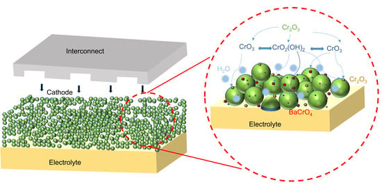
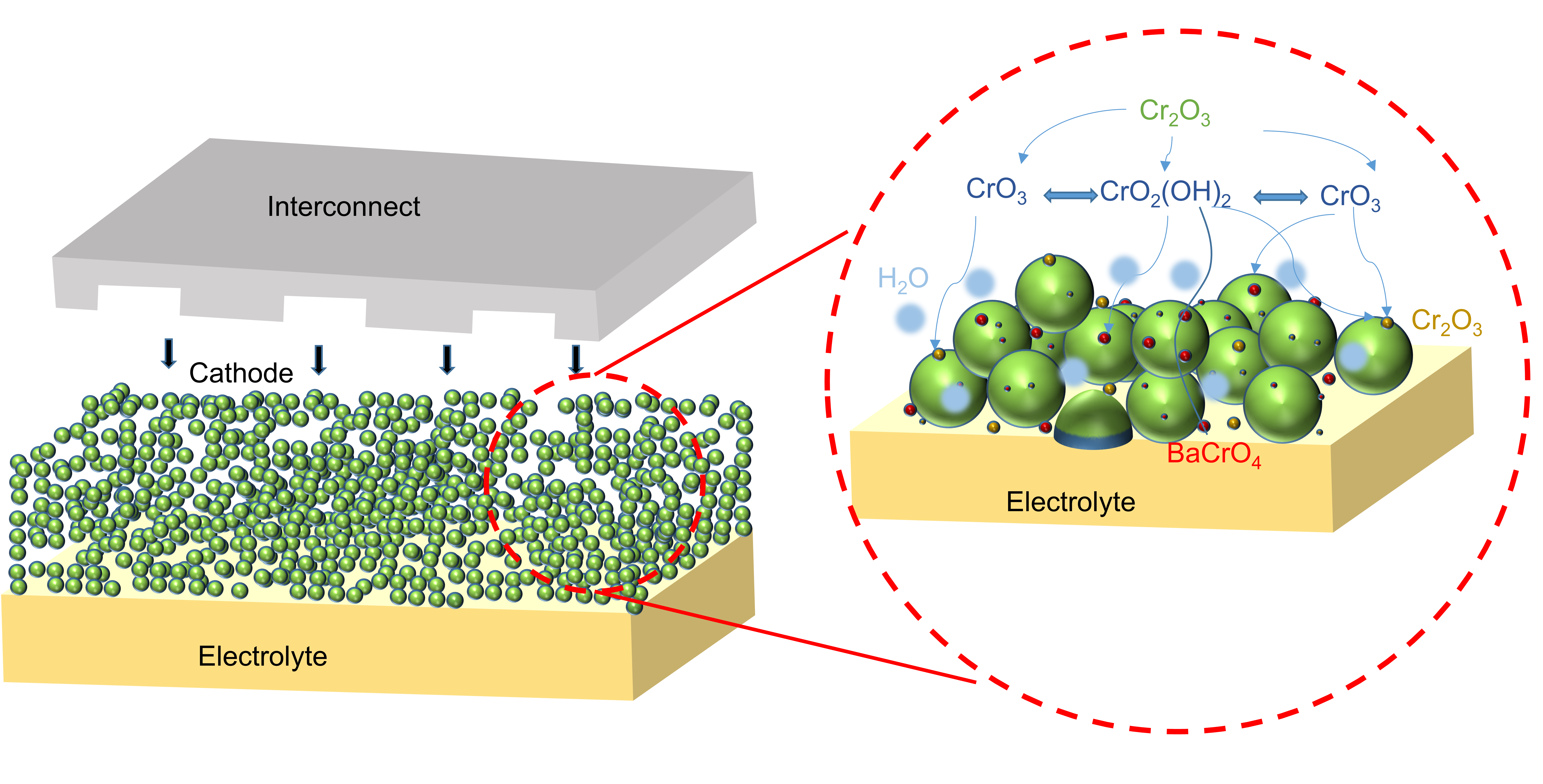
Graphical Abstract

1. Introduction

With the rapid development of industrial society, non-renewable fossil fuel-based energy systems have led to a deterioration in the environment, pollution and the energy crisis, calling for a reshaping of the energy structure toward a sustainable, green, and clean supply of energy and resource. High-temperature solid oxide cells (SOCs) are an innovative energy conversion and storage technology which can convert the chemical energy of fuels such as hydrogen and ammonia to electricity and heat under solid oxide fuel cell (SOFC) operation mode as well as storing renewable solar and wind energy in the form of hydrogen or carbon monoxide under solid oxide electrolysis cell (SOEC) operation mode in a highly efficient and environmentally friendly way [1,2,3]. However, the high-temperature operation of traditional oxide ion-conducting electrolyte-based SOCs faces several challenges such as the high manufacturing and operation cost [4], the thermal mismatch between adjacent components [5], the instability of materials and interfaces [6,7] and the low operation life [8]. Due to the dramatic decrease in O2- conductivity with temperature, lowering the operation temperature is a serious challenge for the commercial viability of SOC technology. On the other hand, considering the increased mobility and decreased activation energy of proton transfer in proton-conducting electrolyte materials such as BaCe0.7Zr0.1Y0.1Yb0.1O3-δ [9] and BaCe0.7Zr0.1Y0.2O3-δ [10], protonic ceramic cells (PCCs) with the dual functionality of protonic ceramic fuel cells (PCFCs) and protonic ceramic electrolysis cells (PCECs) operating at 400–700 °C are promising alternatives at the medium- and low-temperature operation range for effective energy conversion and storage [8,11,12]. PCCs have significant advantages over SOCs, such as the broader range of sealing and interconnect materials that can be selected [13], improved stability [14], no fuel dilution at the fuel electrode side [15], and the shortened start-up and shutdown times [13].
As with SOCs, chromium-forming stainless steel is generally processed into interconnectors (ICs) to join multiple cells in series to assemble a large-scale PCC stack to produce electricity and fuel that satisfy the requirements of practical applications [16]. Under the operating temperatures of PCCs, 400–700 °C, the Fe-Cr alloy interconnect would react with O2 and/or H2O to form a Cr-rich oxide or Cr2O3 scale layer and produce gaseous Cr species such as CrO3 or CrO2(OH)2 in dry and humidified oxidation atmospheres due to the thermodynamic instability of the chromium oxide scale [17]. As one of the most serious degradation issues in SOCs, the effects of Cr deposition and poisoning on the electrochemical activity and stability of the air electrode have been extensively studied [18,19,20]. Chen et al. conducted a comparative experiment on Cr deposition and poisoning of La0.8Sr0.2MnO3 (LSM) under SOFC and SOEC operation modes and found that the (Cr, Mn)3O4 spinel was the main poisoning product in SOFC, while SrCrO4 and chromium oxide were the dominant deposits in SOEC [20]. In addition, the (Cr, Mn)3O4 spinel was found to be formed at the interface region between the LSM air electrode and the yttria-stabilized zirconia (YSZ) electrolyte in SOFC, while SrCrO4 and chromium oxide were deposited primarily on the surface and in the bulk of LSM in SOEC, because anodic polarization accelerated Sr segregation and suppressed Mn segregation in SOEC mode. Komatsu et al. compared the reactive activity between Cr2O3 and three air electrodes, La0.6Sr0.4Co0.2Fe0.8O3 (LSCF), LaNi0.6Fe0.4O3 (LNF) and LSM at 800 °C in SOFC, and reported that the LSM cathode reacted with Cr2O3 to produce the MnCr2O4 spinel and LSCF reacted with Cr2O3 to produce SrCr2O4, CoCr2O4 and (Fe, Cr)2O3, while LNF was tolerant to Cr species [21]. Xie et al. compared the Cr deposit and poisoning behavior of La0.6-xBaxSr0.4Co0.2Fe0.8O3-δ (LBSCF) and BSCF, and it showed the polarization resistance of the cell with the LBSCF electrode was very low when exposed to moist air (~3% H2O) at 800 °C for 120 h [22]. The doping of Ba at the A-site of LSCF could greatly suppress Sr segregation, thus reducing the Cr poisoning effect. Our early study on the Cr deposit and poisoning of the Ba1-xSrxCo0.8Fe0.2O3-δ (BSCF, 0.3 ≤ x ≤ 0.7) air electrodes showed the electrode polarization resistance for the O2 reduction reaction (ORR) process increased when the Fe-Cr metallic interconnects were present, in contrast with the superior and stable electrochemical performance of the BSCF electrodes when Fe-Cr alloy interconnector was absent [23]. The results indicate that both Sr and Ba segregation play a key role in the Cr deposition and poisoning of BSCF cathodes, leading to the formation of SrCrO4 and BaCrO4. The Cr deposition and poisoning are closely related to the Ba/Sr ratio of the cathode. It has been widely recognized that the surface segregation of Ba, Sr, and Mn elements from the air electrode promotes Cr deposition and poisoning of air electrodes of SOCs [20,24,25]. The interaction between the gaseous Cr species and air electrodes under SOC operation conditions can be generally explained by the nucleation theory [17].
CrO3(g) + N(s) → Cr–N–O(nuclei, s)
Cr–N–O(nuclei, s) + CrO3(g) → Cr2O3(s)
Cr–N–O(nuclei, s) + CrO3(g) + N(s) → Cr–N–O(s)
where CrO3(g) is the gaseous Cr species in dry air, which can also be CrO2(OH)2 or Cr(OH)6 in humidified air, N(s) is a nucleation agent, and Cr–N–O(s) is the reaction product between gaseous Cr and the nucleation agent.
Even though LSM and LSCF are widely used in O-SOFC, neither LSM nor LSCF is suitable as the air electrode of PCCs due to a lack of proton conduction ability, which constrains the electrochemical reaction area within electrode–electrolyte contact area and leads to larger polarization loss of PCC [8,22,26,27]. In PCFCs, protons are formed at the anode and then transported to the cathode side to react with O2− to generate H2O. The high-humidity atmosphere at the air electrode would inevitably accelerate Cr evaporation from the Cr2O3 oxidation scale of Cr-forming metallic interconnect [28]. In comparison to the extensive investigation on Cr deposition and poisoning of electrode and electrolyte materials in SOCs, the Cr-related studies in PCCs are relatively scarce. Zhao et al. investigated the Cr poisoning behavior of the BaZr0.1Ce0.7Y0.2O3-δ (BZCY) electrolyte and observed that BZCY reacted with Cr2O3 at 600 °C [29]. Our group systematically studied the Cr deposition and poisoning behavior of the most widely used BaCe0.7Zr0.1Y0.1Yb0.1O3-δ (BCZYYb7111) electrolyte by bringing electrolyte pellets and Cr-containing alloy interconnect into direct contact within the temperature range of 400–700 °C under dry and humidified air conditions [30]. The results evidently showed that the air humidity promoted Ba segregation from the BCZYYb7111 bulk to the surface and reacted with Cr species to form BaCrO4, which in turn accelerated Ba segregation and led to a Ba depletion layer in the electrolyte bulk and a significant reduction in the conductivity of the electrolyte materials.
In PCCs, in order to construct so-called triple-conducting oxides (TCOs) to simultaneously transport H+, O2−, and e [15,31], Ba is an essential constituent element of air electrodes. In addition, a variety of heterovalent elements (Co, Fe, Sc, Y) are also doped into proton conduction oxides (such as BaZrO3 or BaCeO3) to enhance the conductivity of O2- and e [32,33,34]. The study by O’Hayre’s group indicated that the electronic conductivity can be significantly activated by doping transition metal elements such as Co and Fe into BaZrxY1-xO3-δ while maintaining ionic conductivity with significantly improved electrode performance [35]. Ba(Zr0.875-xYb0.125Cox)O3-δ was reported to be an air electrode of PCFC with superior stability when the Cr-forming alloy interconnect was absent [36]. Chen et al. reported that Pr0.9Co0.3Fe0.7O3(PFC) catalyst coating could significantly enhance the ORR activity and stability of the double perovskite PrBa0.5Sr0.5Co1.5Fe0.5O5+δ (PBSCF) cathode for PCFCs when it was exposed to moist air and the Cr-forming alloy interconnect was present, which was attributed to the suppression of Ba segregation by the physical isolation of Cr species from the PBSCF air electrode [37]. Yang et al. reported the performance degradation of the PrBa0.5Sr0.5Co1.5Fe0.5O5+δ air electrode when exposed to volatile Cr species and CO2 [38]. Nevertheless, studies on the Cr deposit and poisoning of air electrode materials of PCCs are rare. The important questions regarding how the Cr species deposit on and poison the air electrode under PCC operation conditions still remain unresolved.
Herein, we selected a triple-conducting oxide, BaCo0.8(Zr0.8Y0.2)0.2O3-δ (BCZY), as a model air electrode to study the Cr deposition and poisoning behavior when exposed to air with different relative humidities (3–50% H2O in air) at 700 °C. As air humidity increased from 3% to 50%, the depth of the deposition layer increased from 0.949 μm to 2.870 μm. For the fuel cell exposed to air with relative humidities of 3% and 50%, after polarization for 50 h, the polarization resistance (Rp) increased by 19.9% and 53.3%, while ohmic resistance (RΩ) increased by 3.5% and 17.1%, respectively. The increased humidity of air not only promoted Cr volatilization from the Fe-Cr alloy but also accelerated surface segregation of Ba from the BCZY electrode, both of which facilitated the formation of BaCrO4 insulating phase on the air electrode. This study systematically evaluates the effect of humidity on chromium deposition and poisoning of the BCZY air electrode, revealing how humidity exacerbates the chromium deposition process, as verified by changes in surface morphology and electrochemical performance. Moreover, this study provides new insights for designing Cr-tolerant materials. Specifically, it highlights that in addition to suppressing surface segregation under high-temperature conditions, as is typically considered in O-SOFCs, attention must also be paid to suppressing surface element segregation in high-humidity environments, which is particularly important for PCFCs.

2. Materials and Methods

2.1. Preparation of Electrode Powder and Cells

The BaCo0.8(Zr0.8Y0.2)0.2O3-δ (BCZY) powder was synthesized by the sol–gel method. In this method, stoichiometric amounts of Ba(NO3)2 (AR, Aladdin, Shanghai, China), Co(NO3)2·6H2O (99.99%, Aladdin, Shanghai, China), Y(NO3)3·6H2O (AR, 99.5%, Aladdin, Shanghai, China), and Zr(NO3)4·5H2O (AR, Macklin, Shanghai, China) were mixed with deionized water in a beaker. The mixture was stirred until the starting materials were completely dissolved, followed by addition of citric acid (CA) and ethylenediaminetetraacetic acid (EDTA) as complexing agents with the molar ratio of metal ions:CA:EDTA = 1:2:1. The pH of the solution was adjusted to be close to 7 using aqua ammonia (GR, 35.05% MW, Aladdin, Shanghai, China). The solution was stirred at 300 °C for 5 h to form a gel and then heated at 180 °C in a furnace for 12 h to generate a self-propagating reaction to form the precursor powder. The precursor powder was calcined at 900 °C for 5 h to obtain BCZY electrode powders.
The BaCe0.7Zr0.1Y0.1Yb0.1O3-δ electrolyte powder was purchased from Shenzhen Tongwei New Energy Co., LTD., Shenzhen, China. BCZYYb7111 electrolyte powder was mixed with 0.5 wt% NiO (sintering aid) and 1 wt% Polyvinyl Butyral (PVB) and ethanol, and then the mixture was ball-milled for 12 h. Then, the electrolyte slurry was poured into a beaker then placed in an electric oven until the mixture was completely dried. After grinding and sieving, the BCZYYb7111 pellets were fabricated by pressing 0.35 g electrolyte powder under 200 MPa pressure each time, and then the pellets were sintered at 1450 °C for 5 h to obtain dense electrolyte pellets with a diameter of 11.2 mm and a thickness of 0.5 mm.
The as-prepared air electrode powder was mixed with organic solvent solution (mass ratio of PVB:terpilenol = 5:95) in a mass ratio of 7:3 to obtain the electrode slurry. Then, the electrode slurry was screen-printed onto the surface of the electrolyte pellet and then sintered at 950 °C for 2 h to obtain a working electrode with an effective area of 0.28 cm2. The platinum paste was coated onto the center of the other side of the electrolyte as the counter electrode with the same area as the working electrode. Additionally, the platinum paste was brushed on the outer ring of the counter electrode as the reference electrode. The painted counter electrode and reference electrode were dried in an oven at 120 °C.

2.2. Cr Deposition and Poisoning Experiment

The reaction reactivity between BCZY and Cr2O3 powders was first studied by mixing BCZY and Cr2O3 powders at a molar ratio of 1:1, then the mixture was put into a crucible placed at the middle of a quartz tube as shown in our previous publication [30]. Thereafter, the mixed powder was heat-treated at temperatures ranging from 350 °C to 700 °C for 20 h with dry (passing through allochronic silica gel) or humidified (~3% H2O) air passing through the quartz tube.
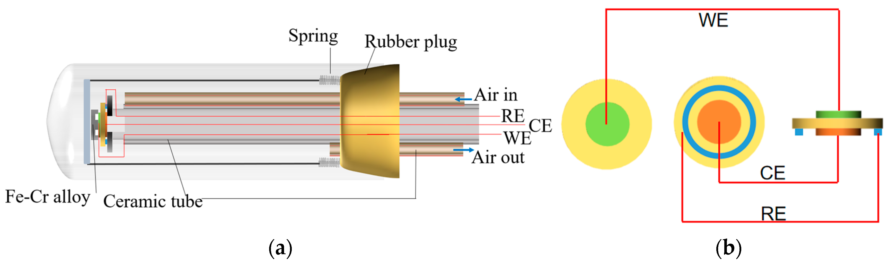
The three-electrode apparatus was designed to investigate the impact of Cr deposition and poisoning on the BCZY air electrode. The experiment setup for the Cr deposition and poisoning of air electrode is displayed in Figure 1. For the direct-contacting poisoning experiment, the interconnector plate used is made of SUS430 stainless steel for its cost-effectiveness and decent corrosion resistance, similar to that used in our previous study [30]. It was fabricated into single-sided grooved specimens measuring 1 cm in diameter, similar to those used in SOFCs [39]. The SUS430 alloy coupon was placed directly on the BCZY air electrodes and fixed by applying a certain pressure by spring to achieve good contact with the electrode. The silver wire was connected to the surface of the alloy plate and a current density of 0.2 A cm−2 was applied to the electrode. For the half-cell in the absence of the alloy plate, Ag paste was screen-printed onto the surface of the BCZY electrode to collect current, with the area close to the current collector of the half-cell when the Cr-forming alloy was present. The Cr poisoning experiment of BCZY was conducted at 700 °C. Although the typical operating temperature of PCFC is below 700 °C, for large-scale cells loaded with higher current density, the operation temperature may be close to or above 700 °C. Therefore, 700 °C was selected as the experimental temperature to accelerate Cr poisoning in this study. It could be expected that with the prolongation of the polarization time of PCFC at 600 °C or lower temperature, the degree of microstructure and electrochemical performance degradation will approach that at 700 °C.

2.3. Measurement and Characterization

The alloy IC was brought into direct contact with the air electrode and the silver wire was drawn out as the current collector. The silver wires were mounted on the surface of the reference and counter electrodes by silver paste (DAD87), and then the half-cell was dried in the electric oven at 180 °C until it was completely cured. The half-cell was placed into a muffle furnace and then heated to 700 °C with a heating rate of 6 °C min−1. Electrochemical impedance spectroscopy (EIS) tests were performed on an electrochemical workstation (Multi Autolab M204, Metrohm Autolab B.V., Utrecht, The Netherlands) to measure the impedance data of the BCZY air electrode before and after Cr poisoning, and the electrode impedance spectra data was collected under the open-circuit voltage (OCV) condition with a frequency ranging from 0.1 Hz to 1 MHz and an AC voltage amplitude of 10 mV. The polarization current of 0.2 A cm−2 was applied to the cell by an electrochemical workstation (Xinwei neware, Shenzhen, China, CT-4008Tn-5V12A-S1-F), humidified air at a flow rate of 50 mL min−1 was passed into the quartz tube, and the change in atmosphere humidity was achieved by precisely adjusting the gas flow rate of the incoming air and the temperature of the water bath. Dry air at a flow rate of 50 mL/min was passed through a water bath maintained at different temperatures, so that the relative humidity of the air exiting the water bath to enter the quartz tube was 3% (25 °C), 10% (48 °C), 30% (70 °C), and 50% (82 °C), respectively. The distribution of relaxation time (DRT) analysis of the EIS data was implemented to determine the electrode processes using the freely available DRT Tools developed by the group of Francesco Ciucci [40]. For the purpose of comparison, the electrochemical performance of the BCZY electrodes was also studied under identical test conditions without the alloy interconnect.
The structure and phase composition of the mixture of BCZY and Cr2O3 powders after the heat treatment were identified by an X-ray diffractometer (XRD, Bruker D8 Advance, Bruker-AXS, Karlsruhe, Germany). The microstructure and morphology of the BCZY electrode before and after the Cr deposition and poisoning experiment were characterized by scanning electron microscopy (SEM, Zeiss GeminiSEM 500, Oberkochen, Germany). The surface composition and element valance of the BCZY electrodes were examined by X-ray photoelectron spectroscopy (XPS, ESCALAB Xi+, Thermo Fisher SCIENTIFIC, East Grinstead, UK). The composition of the deposit on the surface of cathode was identified by Raman spectroscopy (LabRAM Odyssey, HORIBA Scientific, Palaiseau, France).

3. Results

3.1. Reactivity Between BCZY and Cr2O3

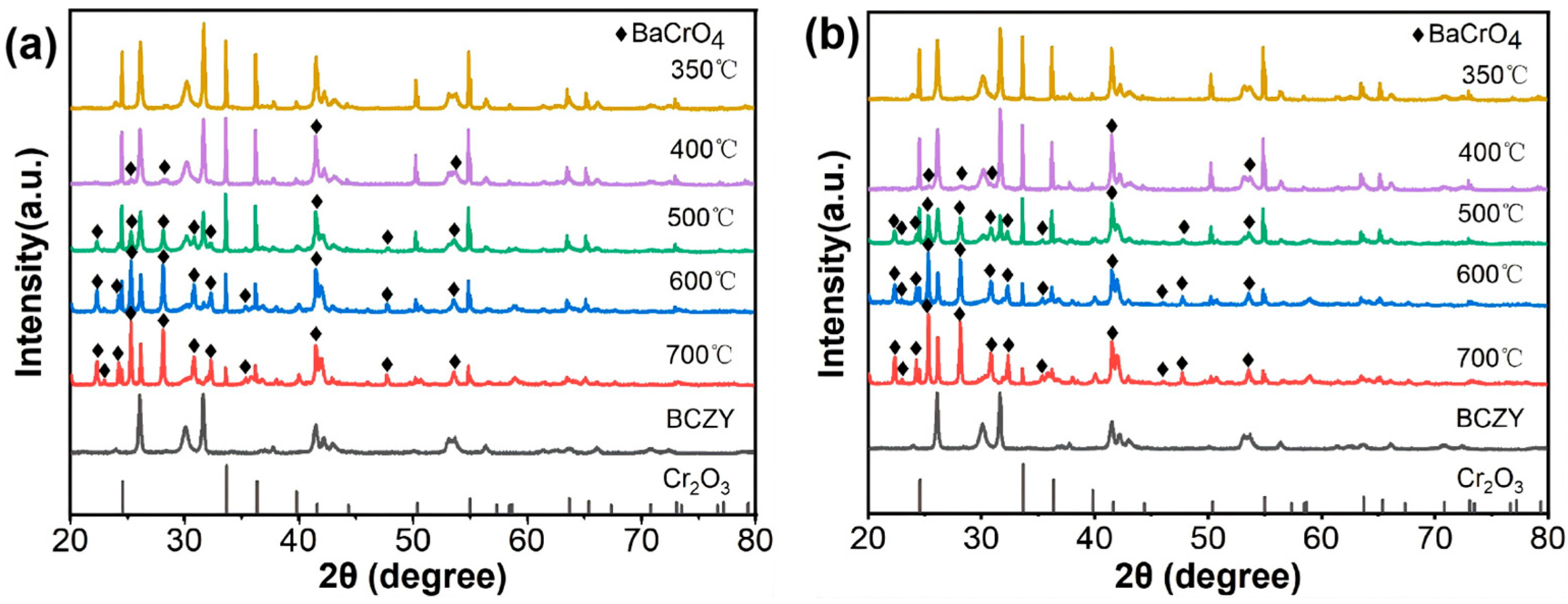
The XRD patterns of the mixed BCZY and Cr2O3 powders after being heat-treated at different temperatures under both dry and humidified air atmosphere are shown in Figure 2. In addition to the BCZY perovskite and Cr2O3 phase, the dominant phase formed after heat treatment of the mixed powders was BaCrO4 with an orthorhombic structure (PDF#00-035-0642). BaCrO4 appeared when the heat treatment temperature was elevated to 400 °C in both dry and humidified air and became dominant at 500 °C. With the increase in temperature, the intensity of the diffraction peaks of BaCrO4 phase became stronger and sharper, and the number of peaks increased. This corresponded to the decrease in the number and intensity of peaks of reactant Cr2O3 and BCZY. The XRD results indicate that BCZY electrode powder can react with Cr2O3 powder to form BaCrO4 at temperatures as low as 400 °C.
The starting reaction temperature between BCZY and Cr2O3 is 400 °C in both dry and humidified air, which implies the strong dependence of reactivity between BCZY and Cr2O3 on temperature. Our early study also showed that the reaction between BaZr0.1Ce0.7Y0.1Yb0.1O3-δ and Cr2O3 powder started at 400 °C [30].

3.2. Microstructure of As-Prepared BCZY Electrode in the Absence of IC

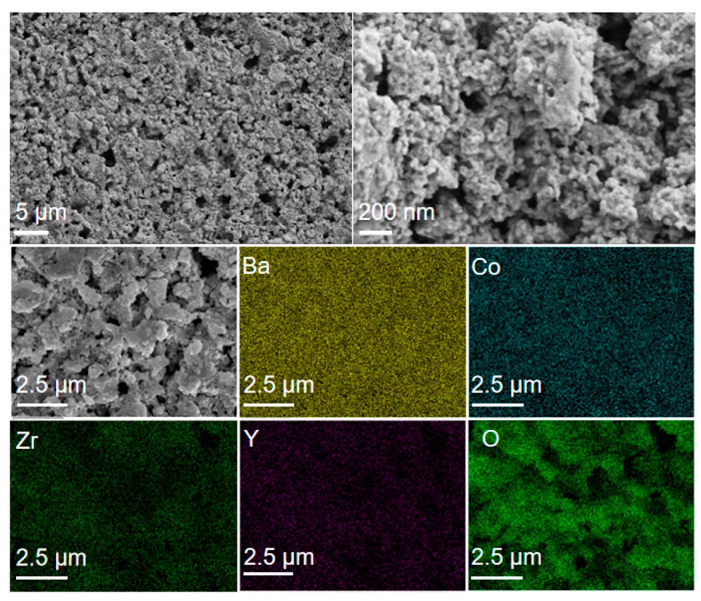
The surface morphology of the as-prepared BCZY air electrode is presented in Figure 3. It can be seen that the BCZY air electrode was porous with a particle size in the range of 52 ± 4 nm, which facilitated gas transport into the electrode and provided the three-phase reaction sites. In addition, the EDS element mapping results indicated that the surface of the BCZY was clean with uniform distribution of the elements comprising the BCZY electrode.
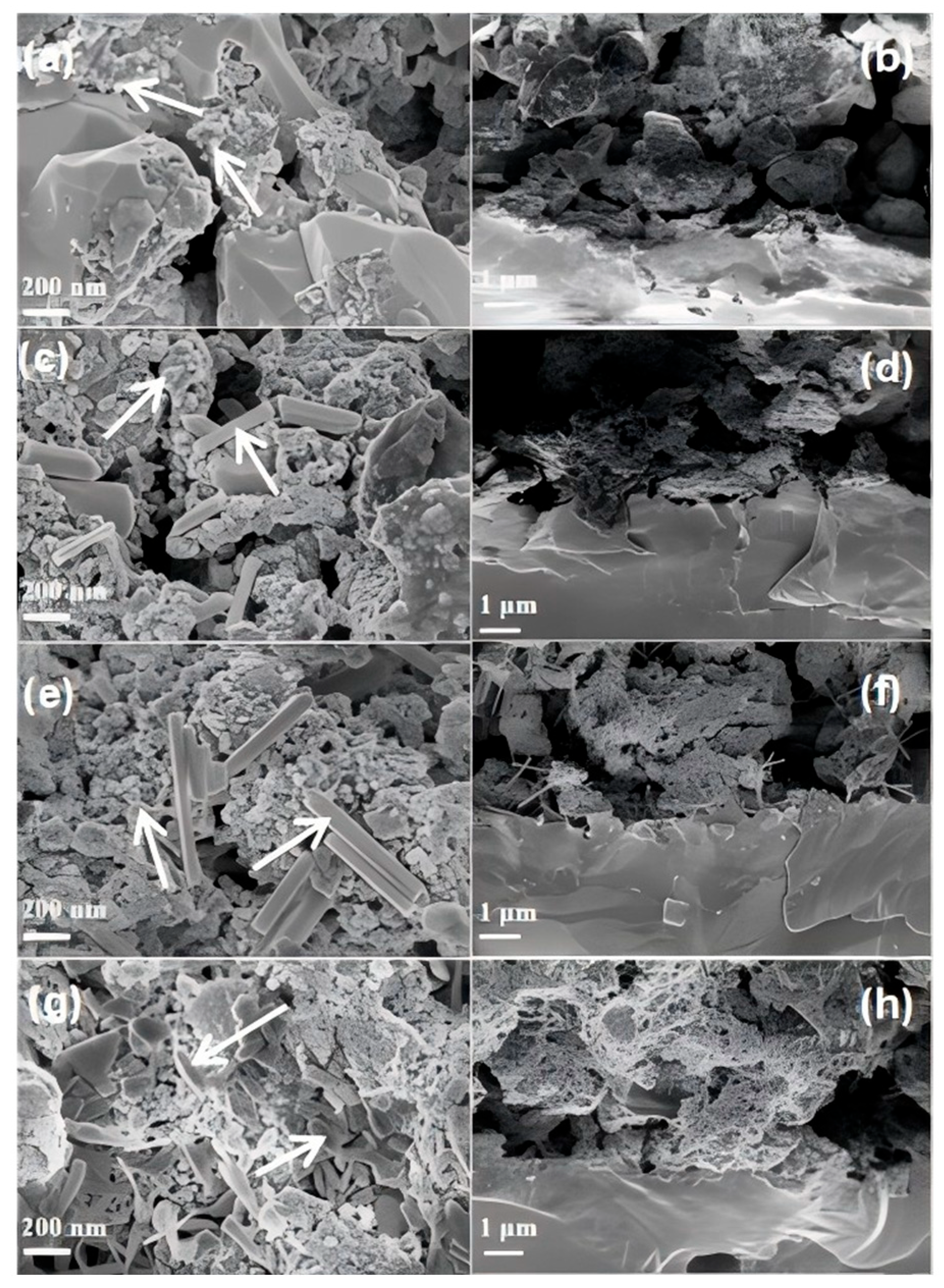
Figure 4 shows the microstructure of the surface and the cross-section of the BCZY electrode after polarization at 0.2 A cm−2 at 700 °C for 50 h under air with relative humidity of 3%, 10%, 30%, and 50% when IC was absent. For the BCZY electrode after exposure to 3% H2O-humidified air with a current density of 0.2 A cm−2 for 50 h, large particles with an average size of 73 nm appeared on the surface of cathode (see Figure 4a). The particles were characterized by clear crystalline faces, which were very different from the original and pristine BCZY particles as shown in Figure 3. The formation of such particles with clear crystalline faces can also be seen in the cross-section of the electrode (Figure 4b). When the humidity was increased to 10%, plate-like particles with the average length of 261 nm and width of 93 nm appeared on the surface (Figure 4c). The plate-like particles grew significantly in size with an average length of ~500 nm and average width of 73 nm on the surface and the cross-section of the BCZY electrode after polarization (Figure 4e,f) at air with 30% humidity. A further increase in the air humidity to 50% led to the growth of the plate-like particles and a significant reduction in the porosity of the BCZY electrodes after polarization, as shown in Figure 4g,h. This indicates that polarization under humidity conditions has a crucial impact on the morphology change in the BCZY electrodes, as indicated by the formation of plate-like particles on the surface and the cross-section of the electrodes.
In PCFCs, both the ORR and the H2O generation reaction occur in the cathode. Hence, when a current is loaded, the H2O partial pressure will increase at the cathode. It was reported that Ba segregation on Ba-based perovskite oxide surface will be aggravated by increasing the humidity of the air passing through it [30]. The influence of the moisture air on the cathode of the cell polarized was studied by adjusting the humidity of the inlet air. At lower humidity (air with 3% H2O), some small particles segregated on the surface of BCZY. With the gradual increase in humidity, the surface morphology of the cathode changed more dramatically. More particles appeared and the segregated particles became larger in size. In addition, fibrous short rod material appeared, which existed on the surface of the electrode and at the electrode–electrolyte interface, as clearly shown in Figure 4c–h. In order to figure out the composition of the segregated nanoparticles, taking the plate-like particle on the surface of BCZY exposed to air with 30% humidity as a representative example, the EDS element analysis of the BCZY electrode (Figure S1 and Table S1, Support Information) was conducted, and the ratio of Ba/(Co+Zr+Y) was larger than 1, suggesting the decomposition of BCZY electrode and the formation of Ba-rich plate-like particles after heat treatment under air with high humidity, which is consistent with the reported results for the BSCF/BCZY composite electrode [41].

3.3. Microstructure and Cr Deposition of BCZY in the Presence of IC

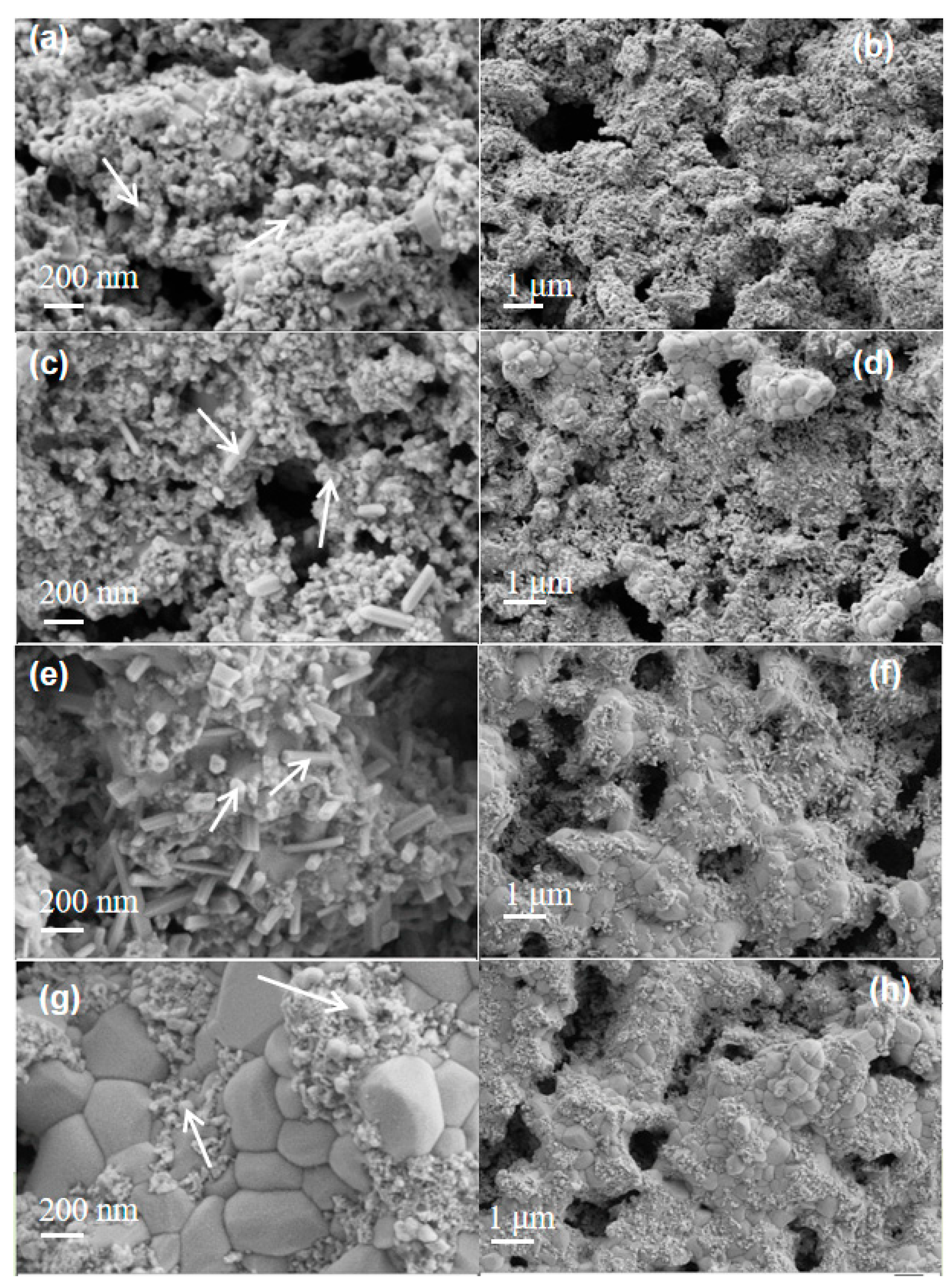
Figure 5 shows the microstructure of the BCZY electrode surface after polarization under a current density of 0.2 A cm−2 in 3%, 10%, 30% and 50% H2O-humidified air at 700 °C for 50 h when the alloy was present. For the electrode after polarization in 3% H2O-humidified air (Figure 5a,b), the surface was largely covered by fine particles with a size similar to that of the pristine BCZY along with a few isolated large particles. With the humidity increased to 10%, a few plate-like particles appeared, similar to those on the surface of the cathode without Cr-forming alloy (see Figure 5c). The average plate-like particle length was 177 nm. The agglomeration of BCZY particles occurred, indicated by the observation of particles with an average diameter of ~2 μm (Figure 5d). When the air humidity was increased to 30%, the density of plate-like particles increased (Figure 5e,f) with an average length of 145 nm. Different from the case without alloy, when the humidity was increased to 50%, plate-like particles changed into round-shaped particles with an average diameter of ~96.5 μm (Figure 5g). The electrode surface is largely covered by the formation of round-shaped particles.
The element mapping of the BCZY electrodes after polarization under different humidities was studied by EDS, and the results are represented in Figure S1 (Supporting Information). It can be seen that only dispersed particle clusters were deposited on the surface of the cathode when the air was humidified by H2O at a molar ratio of 10%. There was no connection between the particle clusters. However, when the humidity was increased to 30%, the particle clusters linked together to form a relatively dense surface covering the BCZY. When the humidity was further increased to 50%, the clusters agglomerated to form a larger and thinner deposit layer on the BCZY electrode surface. From the element mapping results displayed in Figure S2, it can be clearly seen that the deposit on the surface of BCZY was rich in Cr and O elements. In addition, the area occupied by the deposits gradually increased with increasing humidity. Moreover, the surface elements constituting the BCZY air electrode decreased as the humidity increased, which can be ascribed to the coverage of the surface of BCZY by the Cr-containing deposit.
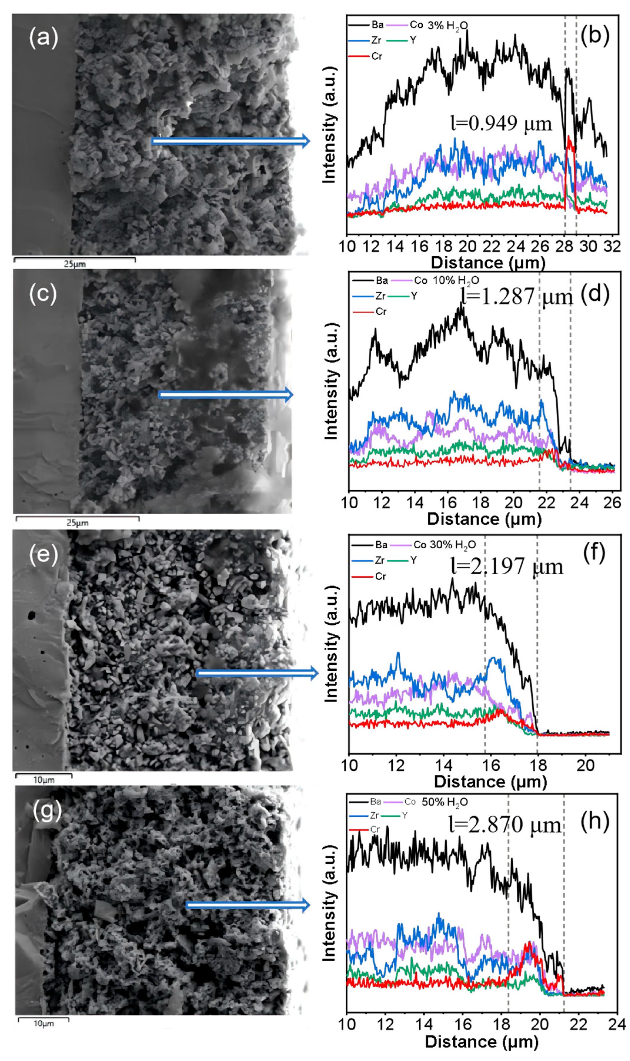
With the Cr-forming IC present, the element distribution along the BCZY electrode as a function of humidity after polarization at a current density of 0.2 A cm−2 at 700 °C for 50 h was studied by EDS line scan of the cross-section of the electrode and electrolyte. In Figure 6, the cross-section of the half-cell is shown with the dense electrolyte on the left and the porous cathode on the right. The white arrow in Figure 6 points from the inner side of the cathode to the outer surface of the cathode.
The change in air humidity affects the evaporation of the Cr-rich oxide scale on Fe-Cr alloy and the surface segregation of BCZY, which has a vital impact on the deposit thickness on the surface of BCZY. When the air humidity was increased from 3% to 30% and further to 50%, after polarization at 0.2 A cm−2 for 50 h, it can be seen from the EDS line scan results that the deposition depth (Ɩ) of Cr showed a gradual increasing trend as a function of humidity, from 0.949 μm in air with 3% H2O to 1.287 μm with 10% H2O, 2.197 μm with 30% H2O, and 2.870 μm with 50% H2O. An obvious Cr-rich layer was produced on the surface of the cathode when the Cr-forming alloy was brought into direct contact with the cathode. With the increase in polarization time and air humidity, the Cr diffusion layer thickness increased. From the XRD results of the powder poisoning experiment shown in Figure 2, it can be inferred that the main composition of the Cr-rich layer is BaCrO4.
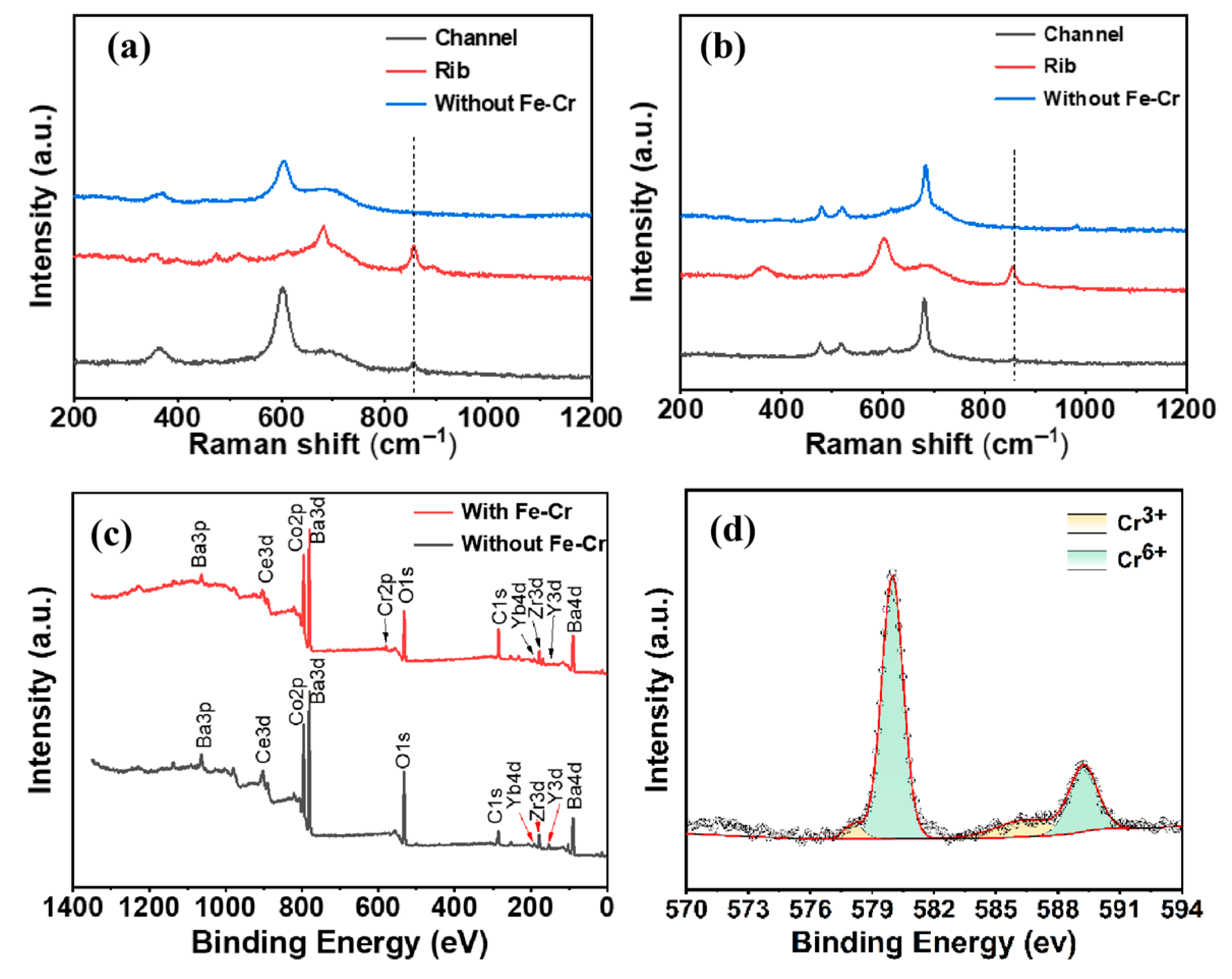
The Cr deposit on the BCZY electrode surface was characterized by Raman spectroscopy and XPS techniques, and the results are displayed in Figure 7. For comparison, the Raman spectrum was also obtained on the BCZY electrode surface after polarization for 50 h at 700 °C under a current density of 0.2 A cm−2 when IC was absent. The deposit on the electrode surface exposed to the rib and channel of the Cr-forming IC was examined. As displayed in Figure 7a,b, it can be clearly observed that there is a peak at 860 cm−1 for the BCZY electrode underneath the channel of the Fe-Cr alloy after polarization, which is associated with CrO42− [30]. The intensity of the peak at 860 cm−1 increased on the surface of BCZY underneath the rib of the alloy IC. Combined with the enrichment of Ba observed in the line scan of the BCZY cathode cross-section, it can be inferred that there is BaCrO4 formation on the BCZY electrode surface. For the cathode area under the rib, both solid diffusion and gaseous diffusion of Cr element occurred simultaneously, while only gaseous diffusion of Cr species took place in the cathode area under the channel. As the solid diffusion rate was faster than the gaseous diffusion rate, the peak intensity of CrO42- corresponding to the area under the rib was significantly stronger than that under the channel, indicating a higher content of BaCrO4 formation on the electrode surface in direct contact with the rib of the Fe-Cr alloy IC.
The XPS results further confirmed that the deposit on the surface of the BCZY cathode in contact with the alloy plate after polarization contained Cr species (Figure 7c,d). A distinct peak belonging to the Cr 2p orbital was observed at 580 eV in the XPS full spectrum. To determine the valence state of the deposited Cr species, the Cr 2p orbital was separately fitted with peaks. As shown in Figure 7d, there were both Cr3+ and Cr6+ species in the Cr deposits with 85.27% Cr6+ and 14.73% Cr3+. The species containing Cr3+ are most likely associated with physically deposited Cr2O3, while those species containing Cr6+ are most likely associated with chemically deposited BaCrO4. The predominant presence of Cr6+ species indicates that the main deposits resulting from the chemical reaction between the gaseous Cr species and the segregated Ba on the BCZY electrode surface are BaCrO4.

3.4. Electrochemical Activity of BCZY Electrodes in the Absence and Presence of IC

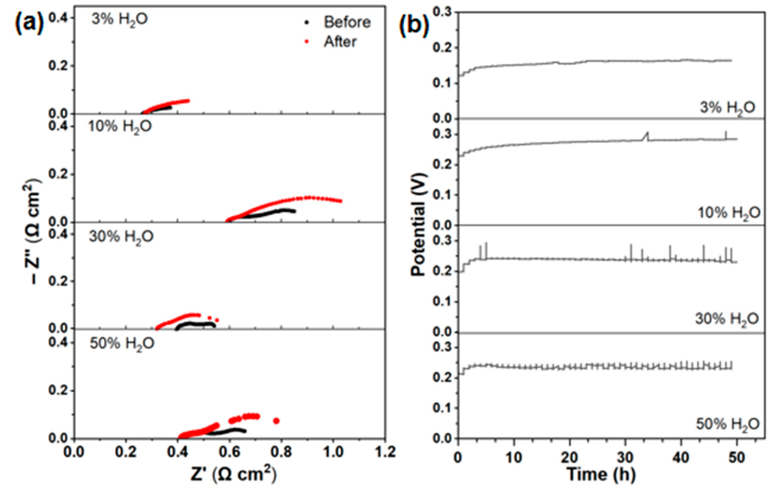
Figure 8 shows the electrochemical impedance curves and stability of the BCZY electrodes when the alloy interconnector was absent, before and after polarization at a current density of 0.2 A cm−2 for 50 h, at 700 °C in air with 3%, 10%, 30%, 50% humidities. The ohmic area-specific resistance (ASR), RΩ, was determined as the high-frequency intercept of the impedance curve with the real axis. The results demonstrated that the change in the RΩ was very small after polarization for 50 h in air with different humidities. For example, the RΩ values of the pristine BCZY electrodes before polarization were 0.263, 0.598, 0.247 and 0.419 Ω cm2, very close to 0.270, 0.588, 0.235, and 0.405 Ω cm2 obtained after polarization under humidified air with 3%, 10%, 30%, 50% H2O, respectively. This also indicated that the formation of plate-like particles on the BCZY electrode surface after exposure to air with different humidities following polarization (as shown in Figure 4) had little effect on the electrode ohmic resistance. However, as can be seen from the impedance data of the electrodes before and after polarization under different humidity conditions, the electrode polarization resistance, Rp, changes most significantly after polarization. The Rp changed from 0.229, 0.375, 0.236, 0.337 Ω cm2 of the pristine BCZY electrodes to 0.322, 0.641, 0.410, 0.486 Ω cm2, respectively, after polarization under humidities of 3%, 10%, 30%, and 50% for 50 h. The total electrode polarization resistance increased by 3.97%, 26.31%, 33.63%, and 17.77%, respectively, after polarization under humidities of 3%, 10%, 30%, and 50% for 50 h. Nevertheless, the electrode showed a relatively stable voltage except for an initial increase in the cell voltage (Figure 8b).
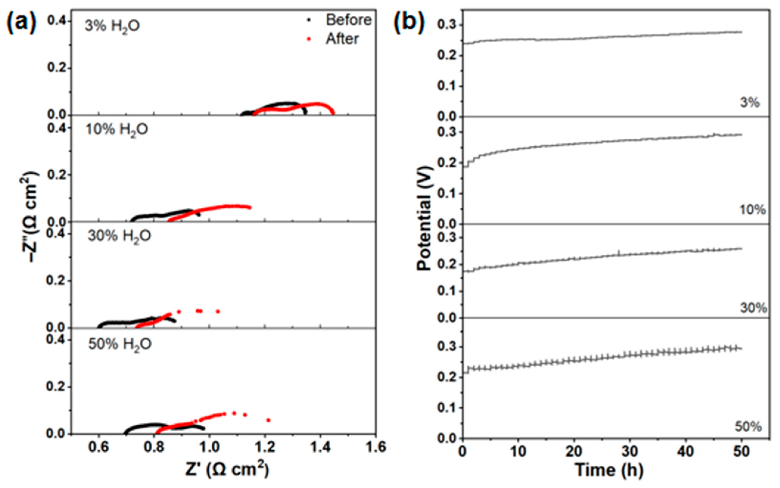
Different from what was observed when the Cr-forming alloy plate was absent, the RΩ of the BCZY electrodes changed dramatically after polarization at a current density of 0.2 A cm−2 for 50 h, at 700 °C, in air with relative humidities of 3%, 10%, 30%, and 50%, as shown in Figure 9. The initial RΩ of the BCZY electrodes before polarization was 1.116, 0.718, 0.601, and 0.685 Ω cm2, then it changed to 1.155, 0.851, 0.735, and 0.803 Ω cm2, measured after polarization for 50 h under humidities of 3%, 10%, 30%, and 50%, respectively. The electrode ohmic resistance increased by 3.5%, 18.5%, 22.2%, and 16.2%, respectively, after polarization for 50 h under the humidities of 3%, 10%, 30%, and 50%. The polarization resistance also increased respectively from 0.246, 0.303, 0.332, and 0.319 Ω cm2 measured under humidity of 3%, 10%, 30%, and 50% before polarization to 0.295, 0.457, 0.498, and 0.489 Ω cm2 after polarization for 50 h under the same humidity conditions. The increase in Rp was 19.9%, 50.8%, 50%, 53.3%, respectively. The results clearly showed that the Cr deposition on the BCZY electrode surface greatly increased the electrode resistance, as indicated by the evident increase in the electrode ohmic resistance of the BCZY electrodes after polarization in the presence of the alloy plate, compared to that in the absence of the alloy plate. Table S2 summarizes the electrode ohmic resistance and polarization resistance measured in air with different humidities before and after polarization at a current density of 0.2 A cm−2 for 50 h at 700 °C. In both conditions, the polarization resistance increased significantly, which may be ascribed to the sensitivity of the polarization process to the surface morphology change in BCZY. The DRT result in Figure S3 indicates the negative effect of surface morphology change on the gas diffusion and surface reaction processes in BCZY cathode. In addition, studies by fellow researchers have also indicated a significant increase in polarization resistance after Cr poisoning of air electrodes in both O-SOFC and PCFC (Table 1).
As shown in Figure 9b, different from the case without the alloy plate, the voltage of the cell with the BCZY electrode contacting the Cr-forming alloy plate increased with polarization time during the 50 h polarization process. As listed in Table S3, the voltage respectively increased from initial values of 0.240, 0.188, 0.173, 0.215 V to 0.278, 0.292, 0.258, 0.293 V after polarization for 50 h in air with humidities of 3%, 10%, 30%, and 50%, increasing by 15.8%, 55.3%%, 49.1%, and 36.3%, respectively. Furthermore, this increasing trend would continue with the further extension of polarization time. The deterioration in the stability of the cells with BCZY electrodes is most likely related to the effect of Cr deposition and poisoning of the electrode on the ORR process in the electrode. With the prolongation of polarization time, the effect of Cr deposit and poisoning of the cathode on both the ohmic resistance and the polarization resistance would be more significant.

3.5. Cr Deposition and Poisoning Process and Mechanism of BCZY

The deposition and poisoning effects of Cr on the cathode have a close correlation with air humidity. There are various reasons for this phenomenon. Firstly, the hydrophilicity of alkaline earth element Ba makes the surface morphology of Ba-based perovskite susceptible to the influence of moist air. Moreover, Ba element tends to segregate toward surface when the Ba-based perovskite material is exposed to moist air, which has been verified by the experiment results [30]. Secondly, when exposed to humidified air, Cr2O3 will volatilize as expressed in formula [17]:
Cr2O3(g) + xO2(g) → CrO3(g)
Cr2O3(g) + xO2(g) + yH2O(g) → 2CrO2(OH)2(g)
Also, it was reported that the volatility of Cr2O3 showed power law dependence with exponents of 1 and 3/4 for steam and oxygen partial pressure, indicating the strong dependence of Cr volatilization on H2O partial pressure [28]. Therefore, with increasing the relative humidity, the partial pressure of gaseous Cr species will increase. The formed gaseous CrO3 and CrO2(OH)2 will react with BaO or Ba(OH)2 to produce BaCrO4. The reaction between them can be expressed as
BaO(s) + CrO3(g) → BaCrO4(s)
Ba(OH)2(s) + CrO3(g) → BaCrO4(s) + H2O(g)
Ba(OH)2(s) + CrO2(OH)2(g) → BaCrO4(s) + H2O(g)
Firstly, the increased air humidity will increase the partial pressure of CrO2(OH)2, which will facilitate the reaction between CrO2(OH)2 and BaO. Then, the depletion of Ba in the near surface of BCZY will induce a larger Ba concentration gradient from the bulk to the near surface, which is a driving force for further segregation of Ba. Furthermore, the adsorption of H2O on the surface and the hydration reaction are also potential factors, which will be studied in future work.
In addition to the chemical pathways mentioned above, volatile hexavalent chromium species released from Cr-containing interconnects, such as CrO3 under dry air conditions and CrO2(OH)2 under humidified air conditions, can undergo electrochemical reduction at the air electrode/electrolyte interface, leading to the formation of Cr2O3. Furthermore, they may further react with BaO in an oxidizing atmosphere to generate BaCrO4. The corresponding reaction equations are expressed as follows:
2CrO3(g) + 6e → Cr2O3(s)
CrO2(OH)2(g) + 3e → 1/2Cr2O3(s) + H2O(g) + 3/2O2−
2BaO(s) + Cr2O3(s) + 3/2O2(g) → 2BaCrO4(s)
As described above, the surface morphology of BCZY is dramatically affected by polarization and air humidity. Surface segregation and clusters formation became more obvious with the increase in air humidity. For the BCZY cathode in contact with the Fe-Cr alloy interconnector, the surface deposit, with BaCrO4 as the main composition, gradually accumulated. The deposit depth tended to increase with the increase in air humidity. Surface segregation (without Fe-Cr) and surface deposition (with Fe-Cr) greatly affected the electrochemical performance. After polarization, the ohmic resistance increased distinctly when the cathode was in contact with the Fe-Cr alloy during polarization. However, the polarization resistance of both the half-cell with and without the Fe-Cr alloy increased significantly after the half-cell was exposed to moist air during the 50 h polarization process.
As mentioned above, Cr in the Fe-Cr interconnector is prone to evaporating from the chromium oxide scale, forming gaseous CrO3 or CrO2(OH)2. At the same time, the Ba atoms in the Ba-containing cathode diffuse from the lattice toward the cathode surface and react with the gaseous Cr species to form Ba-Cr-O nuclei, as indicated by Equation (1), which gradually grow to form a Cr-rich layer on the surface, as indicated by Equations (6)–(8). The main component of the reaction product has been proven to be BaCrO4., as indicated by the presence of dominant Cr6+ in the deposits (Figure 7d). Due to the porous structure of the cathode itself, gaseous Cr will also diffuse into the cathode, and the reaction will continue to form Cr deposits inside the cathode, eventually blocking the gas transport channel and the reaction active sites, resulting in a sharp degradation of electrochemical performance.
As shown above, after polarization for 50 h, with the increase in air humidity, plate-like nanoparticles appeared on the surface of BCZY when the Cr-forming alloy plate was absent. Under the same conditions, when the Cr-forming IC was present, particles with the main component of BaCrO4 appeared on the surface of BCZY, while plate-like particles were not visible. After polarization in humidified air, the ohmic resistance of BCZY changed slightly when the Cr-forming alloy plate was absent but increased dramatically when the alloy was present. Overall, the Cr deposition and poisoning processes have an adverse impact on the microstructure and electrochemical performance of the BCZY electrode.

4. Conclusions

In this work, the Cr deposition and poisoning behavior of the BaCo0.8(Zr0.8Y0.2)0.2O3-δ (BCZY) air electrode of proton ceramic fuel cell were investigated. Moreover, the underlying mechanism of Cr poisoning of BaCo0.8(Zr0.8Y0.2)0.2O3-δ was disclosed. The powder poisoning experiment indicated that the mixture of Cr2O3 and BCZY powders reacted at 400 °C in both dry and 3% H2O-humidified air. The surface morphology of the BCZY cathode changed dramatically after polarization at a current density of 0.2 A cm−2 in humidified air even when the Cr-forming alloy interconnector was absent. Surface segregation and the formation of plate-like particles or clusters became more obvious with the increase in air humidity, which had influential effect on polarization resistance rather than ohmic resistance. For the BCZY electrode in contact with the Fe-Cr alloy, the deposition of Cr poisoning reaction products affected both the ohmic resistance and polarization process distinctly. The gaseous Cr species evaporated from the Cr-forming alloy and the Ba atoms segregated from BCZY reacted to form reaction products that deposited on the surface of BCZY. Various characterization techniques verified that the main component of the Cr poisoning reaction product was BaCrO4. When the relative humidity of air increased from 3% to 50% in air, the deposit layer depth increased from 0.949 to 2.870 μm after polarization at 0.2 A cm−2 for 50 h. For the cell exposed to air with 3% and 50% humidity, after polarization at 0.2 A cm−2 for 50 h, the polarization resistance (Rp) increased by 19.9% and 53.3%, while ohmic resistance (RΩ) increased by 3.5% and 17.1%, respectively.

Supplementary Materials

The following supporting information can be downloaded at https://www.mdpi.com/article/10.3390/en19112528/s1, Figure S1: EDS element analysis of surface of BCZY exposed to air with 30% H2O; Figure S2: EDS element mapping of the BCZY cathode in direct contact with Fe-Cr alloy after polarization at 700 °C with a current density of 0.2 A cm−2 for 50 h at air atmosphere with relative humidity of (a) 10% (b) 30% and (c) 50%. Figure S3: The DRT curves of BCZY electrodes before (left) and after (right) polarization at 700 °C and 0.2 A cm−2 in air with 3%, 10%, 30%, and 50% H2O in (a,b) the absence of Fe-Cr alloy and (c,d) the presence of Fe-Cr alloy. Table S1: Element atom ratio of surface deposit of BCZY exposed to air with 30% humidity; Table S2: Ohmic and polarization of BCZY before and after polarization for 50 h. Table S3: Voltage value (V) before and after polarization.

Author Contributions

Conceptualization, L.T.; Methodology, L.T., Z.Y., Z.C., C.C., H.Y., H.T. and M.G.; Validation, L.T.; Formal analysis, L.T., Z.Y. and B.W.; Investigation, L.T., Z.Y. and Z.C.; Resources, Y.-B.C., M.G. and S.P.J.; Data curation, L.T.; Writing—original draft, L.T.; Writing—review and editing, M.G. and S.P.J.; Visualization, L.T.; Supervision, Y.-B.C., and S.P.J.; Project administration, M.G. and S.P.J.; Funding acquisition, M.G. and S.P.J. All authors have read and agreed to the published version of the manuscript.

Funding

This research was funded by Youth Innovation Fund of Foshan Xianhu laboratory (33XHQN2023-002) and Major Project of Foshan Xianhu Laboratory open fund (31XHD2024-31000000-06).

Data Availability Statement

The original contributions presented in the study are included in the article and the supplementary file; further inquiries can be made to the corresponding author.

Conflicts of Interest

All authors were employed by the Foshan Xianhu Laboratory. The authors declare that the research was conducted in the absence of any commercial or financial relationships that could be construed as a potential conflict of interest. The authors declare that this study received funding from Foshan Xianhu Laboratory. The funder was not involved in the study design, collection, analysis, or interpretation of data, the writing of this article or the decision to submit it for publication.

References

  1. Wang, B.; Wang, R.; Lu, R.; Du, Q.; Jiao, K. Development and industrialization progress of solid oxide cell in China. Int. J. Green Energy 2025, 22, 334–342. [Google Scholar] [CrossRef]
  2. Wolf, S.E.; Winterhalder, F.E.; Vibhu, V.; de Haart, L.G.J.; Guillon, O.; Eichel, R.-A.; Menzler, N.H. Solid oxide electrolysis cells-current material development and industrial application. J. Mater. Chem. A 2023, 11, 17977–18028. [Google Scholar] [CrossRef]
  3. Yang, Y.; Lei, J.; Huang, X.; Liao, Z.; Liu, Y.; Tu, Z. Recent Development in Reversible Solid Oxide Fuel Cells: Theory, Integration and Prospective. ChemElectroChem 2023, 11, e202300593. [Google Scholar] [CrossRef]
  4. Zhang, H.; Chen, T.; Huang, Z.; Hu, G.; Zhou, J.; Wang, S. A cathode-supported solid oxide fuel cell prepared by the phase-inversion tape casting and impregnating method. Int. J. Hydrogen Energy 2022, 47, 18810–18819. [Google Scholar] [CrossRef]
  5. Hanif, M.B.; Tsampas, M.N. Pathways to Mitigate Chromium Poisoning in Electrolysis Devices. ACS Appl. Energy Mater. 2025, 9, 26–55. [Google Scholar] [CrossRef]
  6. Pan, Z.; Liu, Q.; Yan, Z.; Jiao, Z.; Bi, L.; Chan, S.H.; Zhong, Z. On the delamination of air electrodes of solid oxide electrolysis cells: A mini-review. Electrochem. Commun. 2022, 137, 107267. [Google Scholar] [CrossRef]
  7. Kim, J.; Ji, H.-I.; Dasari, H.P.; Shin, D.; Song, H.; Lee, J.-H.; Kim, B.-K.; Je, H.-J.; Lee, H.-W.; Yoon, K.J. Degradation mechanism of electrolyte and air electrode in solid oxide electrolysis cells operating at high polarization. Int. J. Hydrogen Energy 2013, 38, 1225–1235. [Google Scholar] [CrossRef]
  8. Wang, Y.; Ling, Y.; Wang, B.; Zhai, G.; Yang, G.; Shao, Z.; Xiao, R.; Li, T. A review of progress in proton ceramic electrochemical cells: Material and structural design, coupled with value-added chemical production. Energy Environ. Sci. 2023, 16, 5721–5770. [Google Scholar] [CrossRef]
  9. Wu, Z.; Zhang, Y.; Liu, Z.; Ma, H.; Jin, X.; Yang, G.; Shi, Y.; Shao, Z.; Li, S. Rapid Gas-Phase Synthesis of the Perovskite-Type BaCe0.7Zr0.1Y0.1Yb0.1O3−δ Proton-Conducting Nanocrystalline Electrolyte for Intermediate-Temperature Solid Oxide Fuel Cells. Appl. Mater. Interfaces 2022, 14, 47568–47577. [Google Scholar] [CrossRef] [PubMed]
  10. Shi, H.; Su, C.; Ran, R.; Cao, J.; Shao, Z. Electrolyte materials for intermediate-temperature solid oxide fuel cells. Prog. Nat. Sci. Mater. Int. 2020, 30, 764–774. [Google Scholar] [CrossRef]
  11. Fernández Muñoz, S.; Chacartegui, R.; Alba, M.D.; Ramírez Rico, J. Optimising anode supported BaZr1-xYxO3-δ electrolytes for solid oxide fuel cells: Microstructure, phase evolution and residual stresses analysis. J. Power Sources 2024, 596, 234070. [Google Scholar] [CrossRef]
  12. Shi, N.; Zhu, K.; Xie, Y.; Huan, D.; Hyodo, J.; Yamazaki, Y. Investigation of Water Impacts on Surface Properties and Performance of Air-Electrode in Reversible Protonic Ceramic Cells. Small 2024, 20, 2400501. [Google Scholar] [CrossRef] [PubMed]
  13. Chun, O.; Jamshaid, F.; Khan, M.Z.; Gohar, O.; Hussain, I.; Zhang, Y.; Zheng, K.; Saleem, M.; Motola, M.; Hanif, M.B. Advances in low-temperature solid oxide fuel cells An explanatory review. J. Power Sources 2024, 610, 234719. [Google Scholar] [CrossRef]
  14. Lee, K.; Kim, Y.; Lee, T.; Kim, G.; Park, J.-S. Enhancing protonic ceramic electrolysis cell performance through electrolyte composition optimization. Ceram. Int. 2024, 50, 40594–40601. [Google Scholar] [CrossRef]
  15. Zohourian, R.; Merkle, R.; Raimondi, G.; Maier, J. Mixed-Conducting Perovskites as Cathode Materials for Protonic Ceramic Fuel Cells: Understanding the Trends in Proton Uptake. Adv. Funct. Mater. 2018, 28, 1801241. [Google Scholar] [CrossRef]
  16. Wang, R.; Sun, Z.; Choi, J.-P.; Choi, J.-P.; Stevenson, J.W.; Stevenson, J.W. Ferritic stainless steel interconnects for protonic ceramic electrochemical cell stacks: Oxidation behavior and protective coatings. Int. J. Hydrogen Energy 2019, 44, 25297–25309. [Google Scholar] [CrossRef]
  17. Jiang, S.P.; Chen, X. Chromium deposition and poisoning of cathodes of solid oxide fuel cells—A review. Int. J. Hydrogen Energy 2014, 39, 505–531. [Google Scholar] [CrossRef]
  18. Gao, Y.; Ling, Y.; Wang, X.; Jin, F.; Meng, D.; Lv, Z.; Wei, B. Sr-deficient medium-entropy Sr1-xCo0.5Fe0.2Ti0.1Ta0.1Nb0.1O3-δ cathodes with high Cr tolerance for solid oxide fuel cells. Chem. Eng. J. 2024, 479, 147665. [Google Scholar] [CrossRef]
  19. Li, J.; Yan, D.; Zhang, W.; Pu, J.; Chi, B.; Jian, L. The investigation of Cr deposition and poisoning effect on Sr-doped lanthanum manganite cathode induced by cathodic polarization for intermediate temperature solid oxide fuel cell. Electrochim. Acta 2017, 255, 31–40. [Google Scholar] [CrossRef]
  20. Chen, K.; Hyodo, J.; Dodd, A.; Ai, N.; Ishihara, T.; Jian, L.; Jiang, S.P. Chromium deposition and poisoning of La0.8Sr0.2MnO3 oxygen electrodes of solid oxide electrolysis cells. Faraday Discuss. 2015, 182, 457–476. [Google Scholar] [CrossRef]
  21. Komatsu, T.; Chiba, R.; Arai, H.; Sato, K. Chemical compatibility and electrochemical property of intermediate-temperature SOFC cathodes under Cr poisoning condition. J. Power Sources 2008, 176, 132–137. [Google Scholar] [CrossRef]
  22. Xie, M.; Cai, C.; Liu, X.; Xue, K.; Chen, Y.; Peng, J.; Bao, J.; An, S.; Yang, H. Improved Durability of High-Performance Intermediate-Temperature Solid Oxide Fuel Cells with a Ba-Doped La0.6Sr0.4Co0.2Fe0.8O3−δ Cathode. ACS Appl. Mater. Interfaces 2022, 14, 33052–33063. [Google Scholar] [CrossRef]
  23. Kim, Y.-M.; Chen, X.; Jiang, S.P.; Bae, J. Effect of Strontium Content on Chromium Deposition and Poisoning in Ba1−xSrxCo0.8Fe0.2O3−δ(0.3 ≤ x ≤0.7) Cathodes of Solid Oxide Fuel Cells. J. Electrochem. Soc. 2012, 159, B185–B194. [Google Scholar] [CrossRef]
  24. Huang, J.; Qian, J.; Wang, C.C.; Chen, Z.; Zhang, H.; Cheng, Z.; Zhao, L.; Ai, N.; Guan, C.; Shao, Y.; et al. Mitigating chromium attack of cathode for durable solid oxide fuel cells through a strain regulation strategy. Chem. Eng. J. 2025, 514, 163443. [Google Scholar] [CrossRef]
  25. Wang, J.; Yang, Z.; Yang, K.; Chen, Y.; Xiong, X.; Peng, S. Chromium deposition and poisoning on Ba0.9Co0.7Fe0.2Nb0.1O3−δ cathode of solid oxide fuel cells. Electrochim. Acta 2018, 289, 503–515. [Google Scholar] [CrossRef]
  26. Yao, P.; Zhang, J.; Qiu, Q.; Zhao, Y.; Yu, F.; Li, Y. Enhancing Oxygen Reduction Kinetics and Proton Transfer of La0.6Sr0.4Co0.2Fe0.8O3−δ Cathode through Pr2Ni0.5Co0.5O4−δ Impregnation for Protonic Ceramic Fuel Cells. Adv. Energy Mater. 2024, 15, 2403335. [Google Scholar] [CrossRef]
  27. Yao, P.; Zhang, J.; Qiu, Q.; Li, G.; Zhao, Y.; Yu, F.; Li, Y. Design of a perovskite oxide cathode for a protonic ceramic fuel cell. Ceram. Int. 2024, 50, 2373–2382. [Google Scholar] [CrossRef]
  28. Elizabeth, J.O.; Nathan, S.J.; Dwight, L.M.; Copland, E.H. Predicting Oxide Stability in High-Temperature Water Vapor. JOM 2006, 58, 22–28. [Google Scholar] [CrossRef]
  29. Zhao, L.; Ding, D.; Zhang, L.; Gui, L.; Wang, Z.; Wan, Y.; Wang, R.; Ling, Y.; He, B. The effect of Cr deposition and poisoning on BaZr0.1Ce0.7Y0.2O3-δ proton conducting electrolyte. Int. J. Hydrogen Energy 2014, 39, 18379–18384. [Google Scholar] [CrossRef]
  30. Guo, M.; Li, Z.; Tang, L.; Li, J.; Wang, Z.; Wang, B.; Shao, Z.; Jiang, S.P.; Yue, Z. Chromium deposition and poisoning of the proton-conducting BaZr0.1Ce0.7Y0.1Yb0.1O3−δ electrolyte of protonic ceramic cells. J. Mater. Chem. A 2025, 13, 15892–15906. [Google Scholar] [CrossRef]
  31. Zohourian, R.; Merkle, R.; Maier, J. Proton uptake into the protonic cathode material BaCo0.4Fe0.4Zr0.2O3-δ and comparison to protonic electrolyte materials. Solid State Ion. 2017, 299, 64–69. [Google Scholar] [CrossRef]
  32. Oikawa, I.; Takamura, H. Correlation among Oxygen Vacancies, Protonic Defects, and the Acceptor Dopant in Sc-Doped BaZrO3 Studied by 45Sc Nuclear Magnetic Resonance. Chem. Mater. 2015, 27, 6660−6667. [Google Scholar] [CrossRef]
  33. Meng, Y.; Gao, J.; Zhao, Z.; Amoroso, J.; Tong, J.; Brinkman, K.S. Review: Recent progress in low-temperature proton-conducting ceramics. J. Mater. Sci. 2019, 54, 9291–9312. [Google Scholar] [CrossRef]
  34. Rashid, N.L.R.M.; Samat, A.A.; Jais, A.A.; Somalu, M.R.; Muchtar, A.; Baharuddin, N.A.; Wan Isahak, W.N.R. Review on zirconate-cerate-based electrolytes for proton-conducting solid oxide fuel cell. Ceram. Int. 2019, 45, 6605–6615. [Google Scholar] [CrossRef]
  35. Duan, C.; Tong, J.; Shang, M.; Nikodemski, S.; Sanders, M.; Ricote, S.; Almansoori, A.; O’Hayre, R. Readily processed protonic ceramic fuel cells with high performance at low temperatures. Science 2015, 349, 1321. [Google Scholar] [CrossRef]
  36. Mikami, Y.; Goto, T.; Asano, H.; Kasuga, K.; Yamauchi, K.; Kuroha, T.; Okuyama, Y. Performance of protonic ceramic fuel cells with Ba(Zr,Yb,Co)O3-δ cathodes and the impact of Co contained in cathode on durability. J. Power Sources 2024, 613, 234832. [Google Scholar] [CrossRef]
  37. Zhang, H.; Xu, K.; He, F.; Zhou, Y.; Sasaki, K.; Zhao, B.; Choi, Y.; Liu, M.; Chen, Y. Surface Regulating of a Double-Perovskite Electrode for Protonic Ceramic Fuel Cells to Enhance Oxygen Reduction Activity and Contaminants Poisoning Tolerance. Adv. Energy Mater. 2022, 12, 2200761. [Google Scholar] [CrossRef]
  38. Le, L.Q.; Meisel, C.; Hernandez, C.H.; Huang, J.; Kim, Y.; O’Hayre, R.; Sullivan, N.P. Performance degradation in proton-conducting ceramic fuel cell and electrolyzer stacks. J. Power Sources 2022, 537, 231356. [Google Scholar] [CrossRef]
  39. Xiong, C.; Li, W.; Duan, N.; Pu, J.; Chi, B.; Jian, L. The effect of molybdenum on chromium deposition at (La0.8Sr0.2)0.95MnO3-δ cathode of solid oxide fuel cells. Int. J. Hydrogen Energy 2016, 41, 9529–9537. [Google Scholar] [CrossRef]
  40. Wang, Z.; Wang, Y.; Py, B.; Maradesa, A.; Liu, J.; Wan, T.H.; Saccoccio, M.; Ciucci, F. DRTtools: Freely Accessible Distribution of Relaxation Times Analysis for Electrochemical Impedance Spectroscopy. ACS Electrochem. 2025, 1, 2680–2689. [Google Scholar] [CrossRef]
  41. Bausá, N.; Solís, C.; Strandbakke, R.; Serra, J.M. Development of composite steam electrodes for electrolyzers based on barium zirconate. Solid State Ion. 2017, 306, 62–68. [Google Scholar] [CrossRef]
  42. Wei, B.; Chen, K.; Wang, C.C.; Lü, Z.; Jiang, S.P. Performance degradation of SmBaCo2O5+δ cathode induced by chromium deposition for solid oxide fuel cells. Electrochim. Acta 2015, 174, 327–331. [Google Scholar] [CrossRef]
  43. Kim, Y.-M.; Chen, X.; Jiang, S.P.; Bae, J. Chromium Deposition and Poisoning at Ba0.5Sr0.5Co0.8Fe0.2O3-δ Cathode of Solid Oxide Fuel Cells. Electrochem. Solid-State Lett. 2011, 14, B41–B45. [Google Scholar] [CrossRef]
  44. Qiu, P.; Li, J.; Jia, L.; Chi, B.; Pu, J.; Li, J.; Chen, F. LaCoO3-δ coated Ba0.5Sr0.5Co0.8Fe0.2O3-δ cathode for intermediate temperature solid oxide fuel cells. Electrochim. Acta 2019, 319, 981–989. [Google Scholar] [CrossRef]
Figure 1. (a) Scheme of the setup for the Cr deposition and poisoning on the surface of BCZY electrodes: (b) details of working electrode (WE), counter electrode (CE) and reference electrode (RE).
Energies 19 02528 g001
Figure 2. XRD patterns of the mixed powders of BCZY and Cr2O3 after heat treatment at 350–700 °C for 20 h under flowing (a) dry air and (b) 3% H2O humidified air.
Energies 19 02528 g002
Figure 3. The surface morphology and EDS element mapping of an as-sintered BCZY electrode.
Energies 19 02528 g003
Figure 4. The surface (left) and cross-sectional (right part) microstructure of BCZY electrode after polarization at 700 °C for 50 h under a current load of 0.2 A cm−2 at air with relative humidity of (a,b) 3%, (c,d) 10%, (e,f) 30% and (g,h) 50% H2O in the absence of Fe-Cr alloy.
Energies 19 02528 g004
Figure 5. Microstructure of the BCZY electrode surface after polarization at 700 °C for 50 h under a current load of 0.2 A cm−2 at (a,b) 3%, (c,d) 10%, (e,f) 30% and (g,h) 50% H2O in the presence of Fe-Cr alloy.
Energies 19 02528 g005
Figure 6. Cross-section and element distribution along line scan of the BCZY electrode after polarization at 700 °C for 50 h under a current load of 0.2 A cm−2 at (a,b) 3%, (c,d) 10%, (e,f) 30% and (g,h) 50% H2O in the presence of Fe-Cr alloy.
Energies 19 02528 g006
Figure 7. Raman spectra of BCZY electrodes under (a) 10% and (b) 50% humidity in the absence and presence of Fe-Cr alloy, (c) XPS full spectrum, (d) Cr 2p orbital energy spectra. The BCZY electrodes were polarized at 700 °C with a current of 0.2 A cm−2 for 50 h before the examination.
Energies 19 02528 g007
Figure 8. (a) Electrochemical impedance spectra and (b) voltage-time curve of BZCY electrodes after polarization at 0.2 A cm−2 and 700 °C under different humidities for 50 h in the absence of Fe-Cr alloy.
Energies 19 02528 g008
Figure 9. (a) Impedance curves of half-cell in the presence of Fe-Cr alloy before and after polarization at 700 °C and 0.2 A cm−2 under 3%, 10%, 30% and 50% humidities and (b) voltage-time curves.
Energies 19 02528 g009
Table 1. Comparison of polarization resistance (Ω cm2) before and after Cr poisoning.
Anode/Electrolyte/CathodeWorking ConditionsBefore Poisoning After Poisoning Poisoning Product
Pt|GDC|SBCO
three-electrode cell
(O-SOFC) [42]
0.2 A cm−2, 20 h, 800 °C, dry air0.180.79BaCrO4 Cr2O3
Pt|GDC|BSCF(O-SOFC)
[43]
0.2 A cm−2, 20 h, 900 °C, dry air0.0260.68BaCrO4 SrCrO4 BaCr2O4
Pt|GDC|BSCF-GDC(O-SOFC) [44]0.4 A cm−2, 20 h, 750 °C, ambient air~0.82 ~2.28BaCrO4 SrCrO4
PBSCF|BCZYYb|PBSCF (PCFC) [37]650 °C, 100 h exposure to Cr species, 3% H2O air0.630.82Cr2O3 BaCrO4 SrCrO4
Pt|BCZYYb|BCZY
(PCFC, this work)
0.2 A cm−2, 50 h, 700 °C, differently humidified air 0.246 (3% RH)
0.303 (10% RH)
0.332 (30% RH)
0.319 (50% RH)
0.295 (3% RH)
0.457 (10% RH)
0.498 (30% RH)
0.489 (50% RH)
BaCrO4 Cr2O3
[42] SBCO: SmBaCo2O5+δ, GDC:Gd0.1Ce0.9O1.95; [43] BSCF: Ba0.5Sr0.5Co0.8Fe0.2O3-d, GDC: Gd0.2Ce0.8O1.95 (GDC); [44] BSCF-GDC: Ba0.5Sr0.5Co0.8Fe0.2O3-δ-Gd0.1Ce0.9O1.9,GDC: Gd0.1Ce0.9O1.9; [37] PBSCF: PrBa0.5Sr0.5Co1.5Fe0.5O5+δ, BCZYYb: BaCe0.7Zr0.1Y0.1Yb0.1O3-δ.
Disclaimer/Publisher’s Note: The statements, opinions and data contained in all publications are solely those of the individual author(s) and contributor(s) and not of MDPI and/or the editor(s). MDPI and/or the editor(s) disclaim responsibility for any injury to people or property resulting from any ideas, methods, instructions or products referred to in the content.