1. Introduction
Conventional mechanical gearboxes, while providing high torque densities, are subject to inherent issues related to contact between toothed surfaces, including wear, the need for lubrication, noise and vibration generation, and limitations in long-term reliability [
1,
2]. Magnetic gears (MGs) represent an alternative capable of transmitting torque without physical contact, exploiting the interaction between magnetic fields produced by permanent magnets and ferromagnetic structures [
3,
4,
5]. Key advantages include intrinsic protection against overloads, the absence of mechanical friction, reduced noise and vibration, and the potential elimination of maintenance [
6,
7,
8]. The Coaxial Magnetic Gear (CMG) reducer, proposed by Atallah and Howe in 2001, marked a turning point by demonstrating torque densities exceeding 100 kNm/m
3, comparable to mechanical planetary reducers [
1,
9]. This topology consists of an inner rotor and an outer rotor, both equipped with permanent magnets having different numbers of pole pairs, and an intermediate ring of ferromagnetic modulating segments which, by modulating the magnetic field, enables harmonic coupling between the two rotors [
8,
10].
Despite its high electromagnetic performance, the conventional CMG presents significant practical challenges: the high cost of rare-earth magnets on both rotors, the construction complexity associated with the precise positioning of the magnets, and the mechanical vulnerability of the high-speed inner rotor due to the centrifugal force acting on the surface magnets [
11,
12,
13,
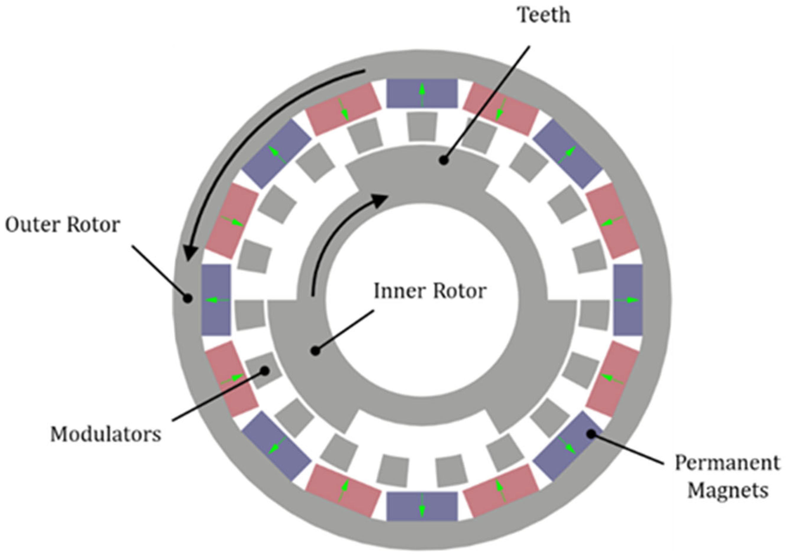
14]. To overcome these limitations, the Reluctance Magnetic Gear (RMG) was introduced (
Figure 1), in which the permanent magnets of the inner rotor are replaced by salient poles made of ferromagnetic material [
11,
12,
15].
The operating principle of the RMG is based on the effect of reluctance modulation. Permanent magnets are present only on the outer rotor, where they generate a magnetic field with a specific spatial harmonic content. The ferromagnetic modulating segments, interposed between the two rotors, modulate this field by introducing additional harmonics into the internal air gap. These modulated harmonics interact with the salient-pole structure of the inner rotor, which exhibits a periodically varying magnetic permeability along the tangential direction. The coupling between the harmonics of the modulated field and the variation in reluctance produced by the ferromagnetic teeth generates a net electromagnetic torque on the inner rotor, enabling the transmission of mechanical power between the two rotors without physical contact and without magnets on the high-speed rotor [
11,
12,
16].
The analytical relationships governing the RMG configuration derive from the condition of harmonic coupling between the components. Let p
1 denote the number of pole pairs on the outer rotor, n
3-the number of teeth (salient poles) on the inner rotor, and GR
int the integer part of the target gear ratio; the number of pole pairs on the outer rotor is calculated as [
15,
16]:
The number of magnets on the outer rotor is equal to n
1 = 2p
1, while the number of modulation segments n
2 is determined by the flux modulation condition [
17]:
The effective gear ratio GR is therefore [
18]:
These relationships highlight how, given the number of teeth n3, the choice of GRint uniquely determines the number of pole pairs, magnets, and modulators, thereby modifying the spatial distribution of the magnetic field harmonics and the coupling conditions between the components.
The adoption of the reluctance topology offers significant advantages in many respects. The inner rotor, being made of a single piece of laminated steel without magnets, is mechanically more robust and inherently suited for high-speed operation, eliminating the risk of magnets detaching due to centrifugal force [
15,
19]. Its manufacture is significantly simpler, as it can be produced as a monolithic component using CNC machining or EDM. The elimination of magnets from the inner rotor directly reduces material costs and eliminates eddy current losses in the high-speed rotor magnets, contributing to an increase in overall efficiency. Furthermore, in the case under examination, rectangular-section magnets are used on the outer rotor, replacing the more expensive custom-made arc magnets, allowing for the use of readily available commercial components at low costs. However, the use of rectangular magnets introduces an inherent increase in torque ripple and a slight decrease in average torque, making performance optimization a particularly significant design challenge.
Torque ripple is one of the most significant performance issues in magnetic gearboxes. A high ripple value causes structural vibrations, acoustic noise, unbalanced magnetic forces, and can trigger resonance phenomena with the natural frequencies of the mechanical system [
20,
21,
22,
23,
24]. Magnetic gearboxes also exhibit significantly lower torsional stiffness compared to traditional mechanical couplings, which amplifies the negative effects of torque oscillations [
3,
25]. For these reasons, minimizing torque ripple is an essential design objective alongside maximizing the average transmitted torque. In automated optimization procedures, excessive ripple is typically classified as a violation of design constraints, and pole combinations that inherently generate high ripple, such as integer gear ratios, are generally avoided [
15,
16,
26].
The gear ratio is a fundamental parameter in the design of coaxial magnetic gearboxes. As shown by Equations (1)–(3), its variation changes the number of pole pairs, magnets, and modulators and, consequently, the spatial distribution of the magnetic field harmonics involved in the coupling [
27]. Different combinations of poles and segments influence not only the maximum achievable torque but also the harmonic structure of the ripple. In the literature, numerous studies have investigated the effect of the gear ratio on the performance of conventional CMGs [
26,
28,
29,
30], and recent studies have addressed the optimization of RMGs using single-objective approaches or parametric analysis [
15,
19]. However, the systematic influence of the GR on the optimal geometric distribution of the design parameters of RMGs, within the framework of a multi-objective optimization that simultaneously considers average torque and ripple, has not yet been thoroughly investigated.
The reluctance topology adopted in this work differs essentially from a conventional CMG in the composition of the optimal inner-rotor allocation, rather than in its overall radial extent. Previous optimization studies on CMGs with surface-mounted PMs on both rotors [
31], although based on a different secondary objective (material cost minimization rather than torque ripple), show that the balanced compromise solution allocates a substantial fraction of the radial span to the inner rotor, comparable to that observed in the present RMG (~60% of the active radial span). The composition of this inner-rotor allocation, however, is essentially different: in the CMG it is split between an inner PM ring (~8 mm) and an inner yoke whose thickness is geometrically constrained to the magnet arc width, while in the RMG the inner rotor is entirely ferromagnetic, with a yoke (dr
6) and salient poles (dr
5) of comparable thickness (~30% of Δr each) freely optimized by the algorithm. The modulator fill factor instead converges to similar values around 0.5 in both formulations, regardless of the secondary objective.
This work aims to fill this gap by investigating, through a multi-objective optimization based on a genetic algorithm, the effect of the gear ratio on the optimal geometric distribution of the design parameters of a coaxial RMG. Four configurations are compared with GRint varying from 4 to 7, while keeping the number of teeth of the inner rotor fixed at n3 = 5. The two optimization objectives are the maximization of the average torque of the inner rotor and the minimization of the percentage ripple. The design variables include five radial thicknesses, expressed in normalized form as weights, and two angular fill factors related to the modulators and the teeth of the inner rotor. The total radial space is kept constant, imposing direct competition among the thicknesses of the various components in the allocation of the available space.
The main objective is to verify whether the gear ratio systematically influences the optimal geometric arrangement resulting from the optimizations, that is, whether a recognizable trend emerges in the allocation of radial thicknesses and fill factors as GRint varies. Since a change in the gear ratio alters the number of pole pairs and modulators, it changes the distribution of the magnetic field harmonics and the conditions for optimal coupling. Understanding whether and how GR determines a different distribution of radial space among the outer rotor, modulators, and inner rotor is of fundamental importance for formulating generalizable design criteria that can guide the preliminary sizing of RMGs even for GR values not explicitly subject to optimization.
2. RMG Model
The parameters defining the overall dimensions, shown in
Table 1, are constrained by application requirements such as shaft diameter, maximum external dimension, and mechanical compatibility. In particular, the outer radius of the outer rotor (r
0) is fixed at 70 mm, while the radius of the inner shaft (r
7) is 27 mm, leaving an available radial space (Δr) of 41 mm for the magnetic circuit layout. The air gap thickness is kept constant at 1 mm, and the axial length of the device is 1000 mm.
Table 2 lists all the parameters characterizing the RMG under consideration. In particular, GR
int has been varied from 4 to 7. By setting the number of salient poles to 5 and given the equations in system (1) and Equation (2), the number of magnets n
1 and the number of modulators n
2 are uniquely determined.
The choice of the number of teeth n3 equal to 5 can be justified by means of a sensitivity analysis of the average torque and ripple as the number of teeth varies, described in the following section.
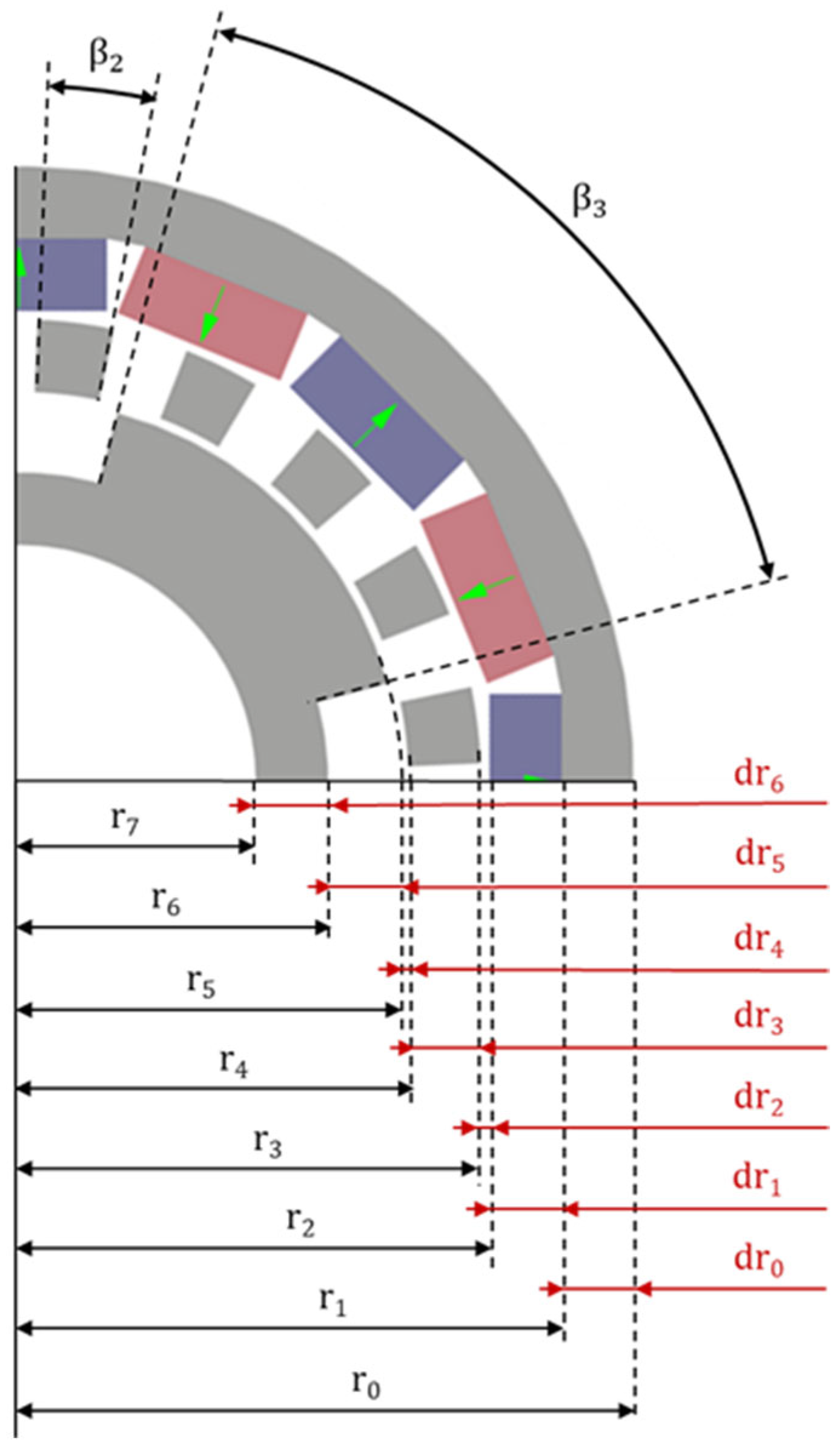
The geometric configuration of the RMG was defined by seven design variables, illustrated in
Figure 2. Five of these variables are radial thicknesses (dr
i), defined as the difference between adjacent radii: dr
0 represents the thickness of the outer rotor yoke, dr
1 the thickness of the permanent magnets, dr
3 the thickness of the modulating segments, dr
5 the thickness of the inner rotor yoke, and dr
6 the height of the inner rotor teeth. These thicknesses must satisfy the geometric constraint imposed by the available radial space:
where m = 0
6, and AG stands for Air Gap, denoted as dr
2 and dr
4 in
Figure 2 and
Table 1.
The intermediate radii of the RMG are calculated from the fixed geometric parameters and the variable radial thicknesses using the following equation:
where r
0 must correspond to the constrained outer radius as shown in
Table 1.
The remaining two variables are the fill factors k
2 and k
3, which characterize the angular extent of the ferromagnetic segments and the teeth of the inner rotor, respectively. The fill factor is defined as the ratio between the angle actually occupied by the ferromagnetic material (β
i) and the available angular pitch (360/n
i):
where k
i is the fill factor, n
i is the number of components used, and i = 2, 3 depending on whether we are considering the modulators or the salient poles of the inner rotor, respectively.
Like dri, the fill factors k2 and k3 also have an intrinsic geometric constraint, in that they cannot be zero; and from Equation (6) it can be seen that they cannot exceed 1, as otherwise there would be overlapping elements. For this reason, during optimization, the filling factors vary within a range between 0.1 and 0.98. Exactly 1 was not considered as the upper limit to avoid problems during the FEM analysis phase.
The materials used for the RMG model under consideration are specified in
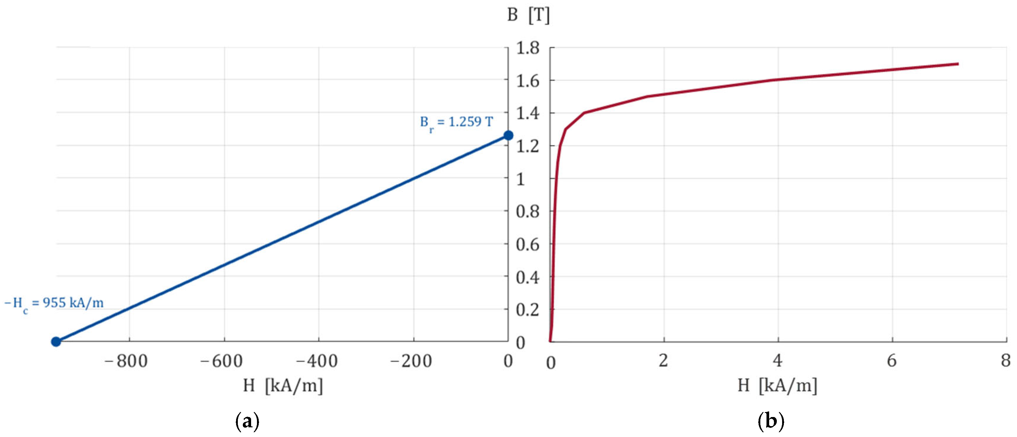
Table 3. The permanent magnets are modeled as N42-grade NdFeB with a remanence B
r = 1.28 T, a relative permeability μ
r of 1.049, and a coercivity of 955 kA/m. The magnetic lamination is M270-35A electrical steel characterized by a nonlinear B-H curve, shown in
Figure 3, and a lamination thickness of 0.35 mm.
3. Torque Density Sensitivity Study
The electromagnetic behaviour of the RMG is analyzed using 2D FEM analysis, implemented in FEMM 4.2 software. The model is based on solving the magnetic vector potential equation, where the reluctance of the materials and the residual magnetization of the permanent magnets determine the magnetic field distribution.
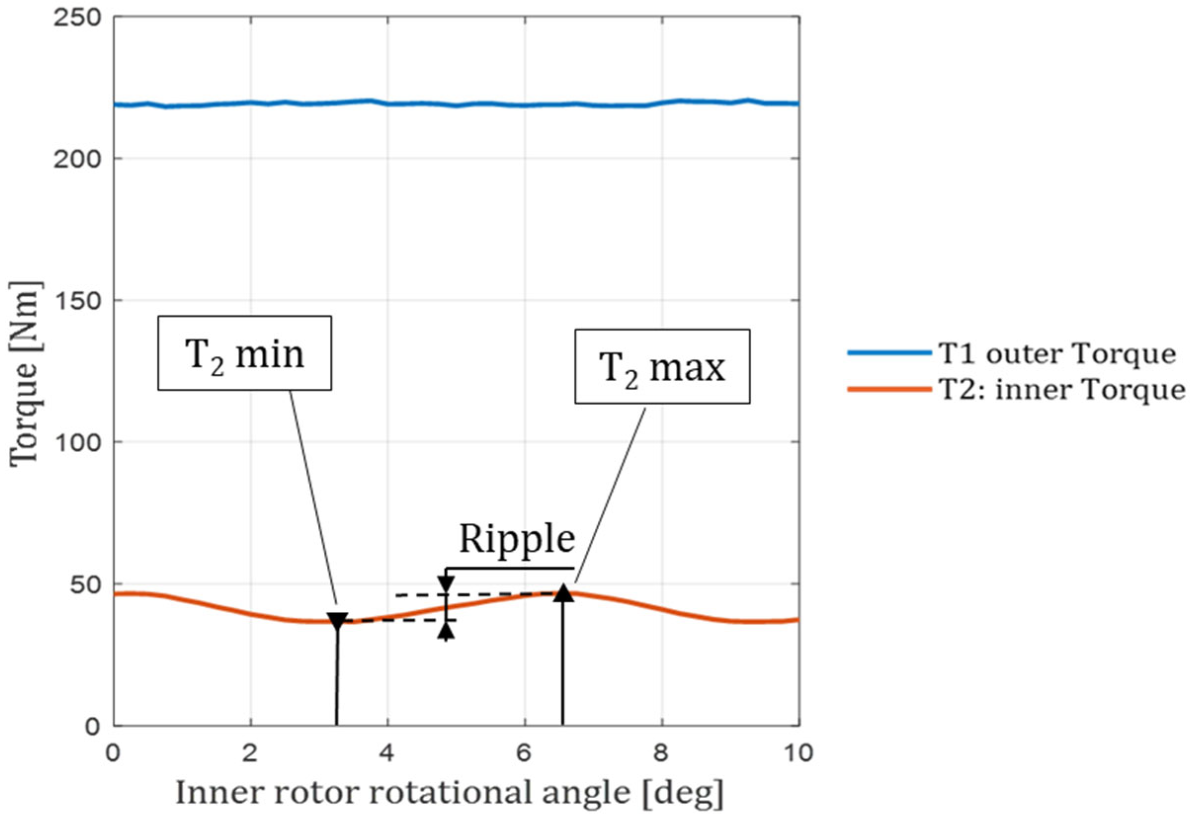
To determine the ripple, a two-step evaluation procedure is employed: (i) the objective is to identify the ϴ
IR,MAX angle between the rotors that maximizes the torque; (ii) the two rotors are rotated simultaneously while maintaining the gear ratio GR starting from the initial phase shift ϴ
IR,MAX. A generic torque ripple curve is shown in
Figure 4.
It can be observed that for the outer rotor, the torque ripple is much smaller than that of the inner rotor, which is why only the inner rotor’s ripple is discussed in this paper.
The percentage ripple was calculated using the following equation:
where T represents the total torque, applied to either the inner or outer rotor depending on where the percentage value of the ripple (R) is to be determined.
3.1. Selection of Inner Rotor Tooth Count
In order to select an appropriate number of teeth, a sensitivity analysis was conducted on the average torque and torque ripple as the gear ratio and the number of salient poles of the inner rotor were varied. These were varied from 3 to 7 for all GR
int models, as shown in
Table 2. Reference is made only to the inner rotor, as it is the most sensitive to torque ripple.
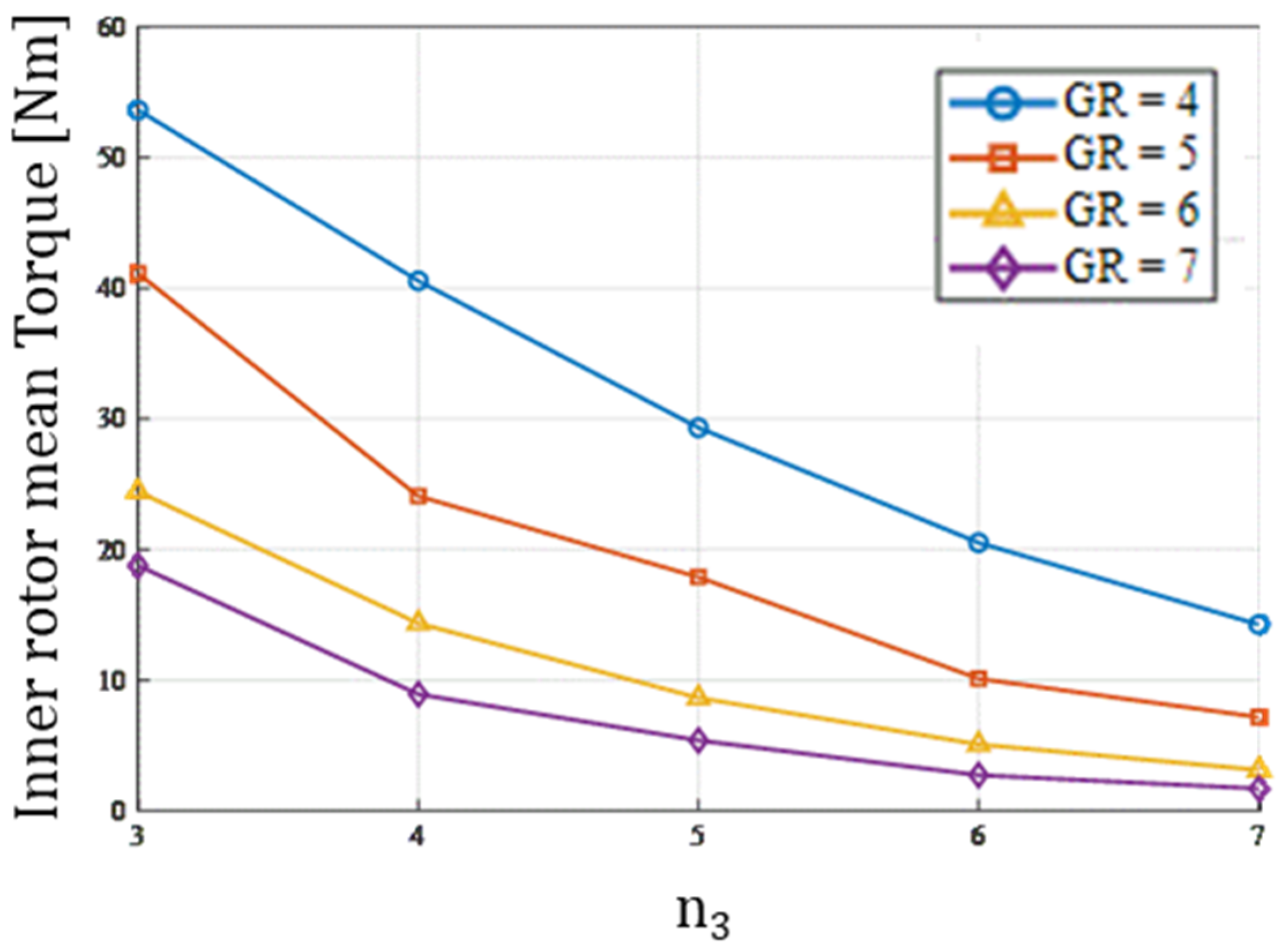
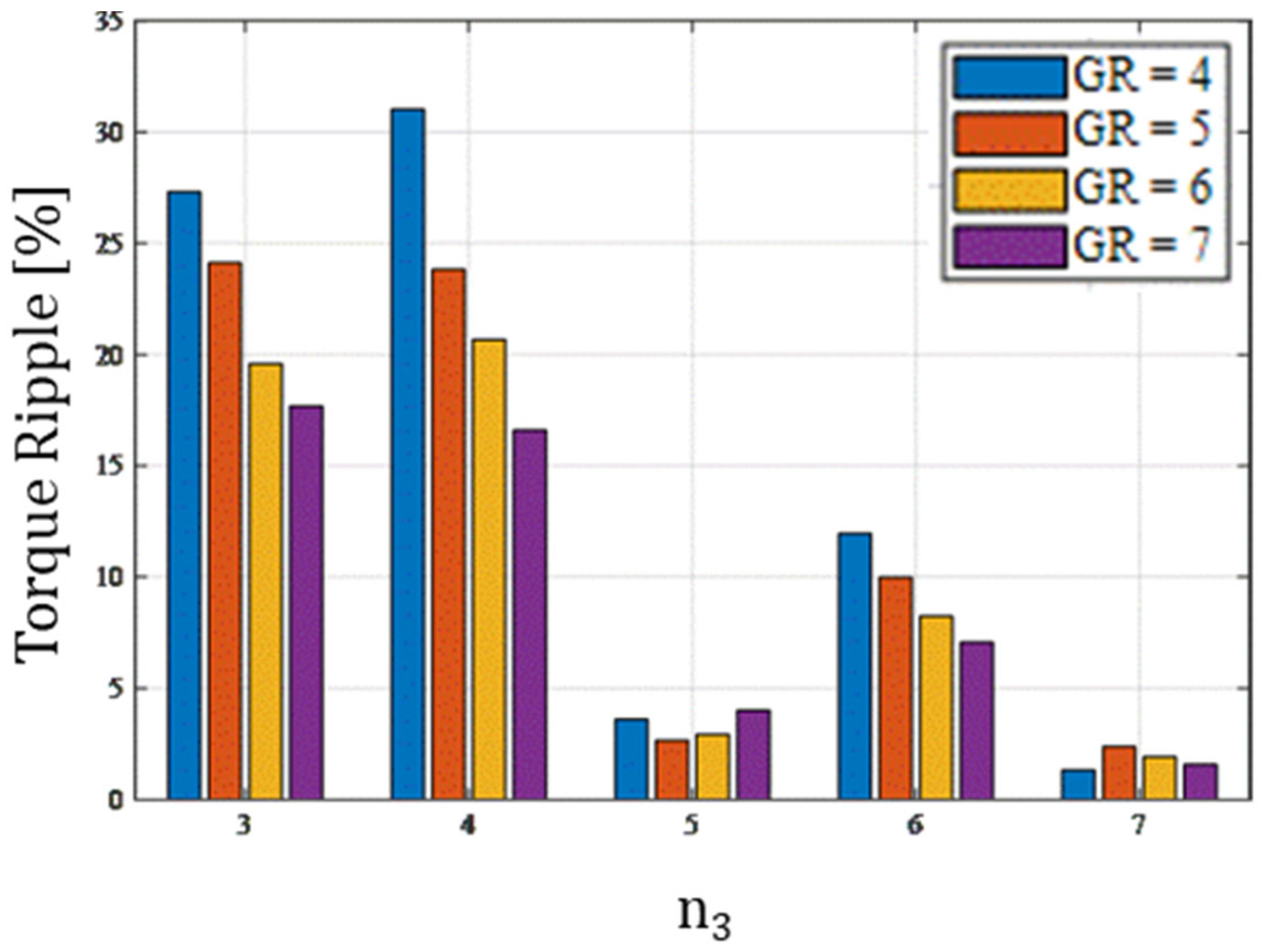
Figure 5 and
Figure 6 show the trends of the average torque and torque ripple of the inner rotor, respectively, as GR
int and the number of teeth n
3 vary. In particular, in
Figure 5, it can be seen that for lower gear ratios, the average torque tends to take on higher values even as the number of teeth varies, and that it tends to decrease as the number of teeth increases. The decrease in torque is more pronounced in magnitude for the configuration with the lowest gear ratio (GR
int = 4), which drops from 53.64 Nm for n
3 = 3 to approximately 14.25 Nm for n
3 = 7; however, in percentage terms, this configuration experiences a decrease of 73.43%. For the configuration with GR
int = 5, the torque ranges from 41.14 Nm for 3 teeth to 7.16 Nm for 7 teeth, this time with a percentage change of 82.60%. Similar calculations can also be performed for the remaining configurations, which show an average percentage change in torque of 87.26% for GR
int = 6 and 90.99% for GR
int = 7. Therefore, it would appear that the increase in the number of teeth has a greater impact on configurations with a higher gear ratio.
Figure 6 shows the ripple value as the number of teeth n
3 and the gear ratio vary. A general trend can be observed: for a lower number of teeth on the internal rotor, the ripple tends to be quite high, even exceeding 20% in the case of lower gear ratios. In fact, it is evident that an increase in the gear ratio reduces the torque ripple. A notable feature is the evident increase in ripple that occurs when the number of teeth is even, due to symmetry. In fact, although this can help cancel out unbalanced magnetic forces, it simultaneously increases the torque ripple [
15].
Based on the above, considering that the average torque tends to decrease as the number of teeth increases, and that the ripple for n3 = 5 is less than 5% for all GRint, this number of teeth was chosen for our study, in an effort to understand whether different GRint can result in different spatial distributions of the main components that make up an RMG.
3.2. Selection of Variables
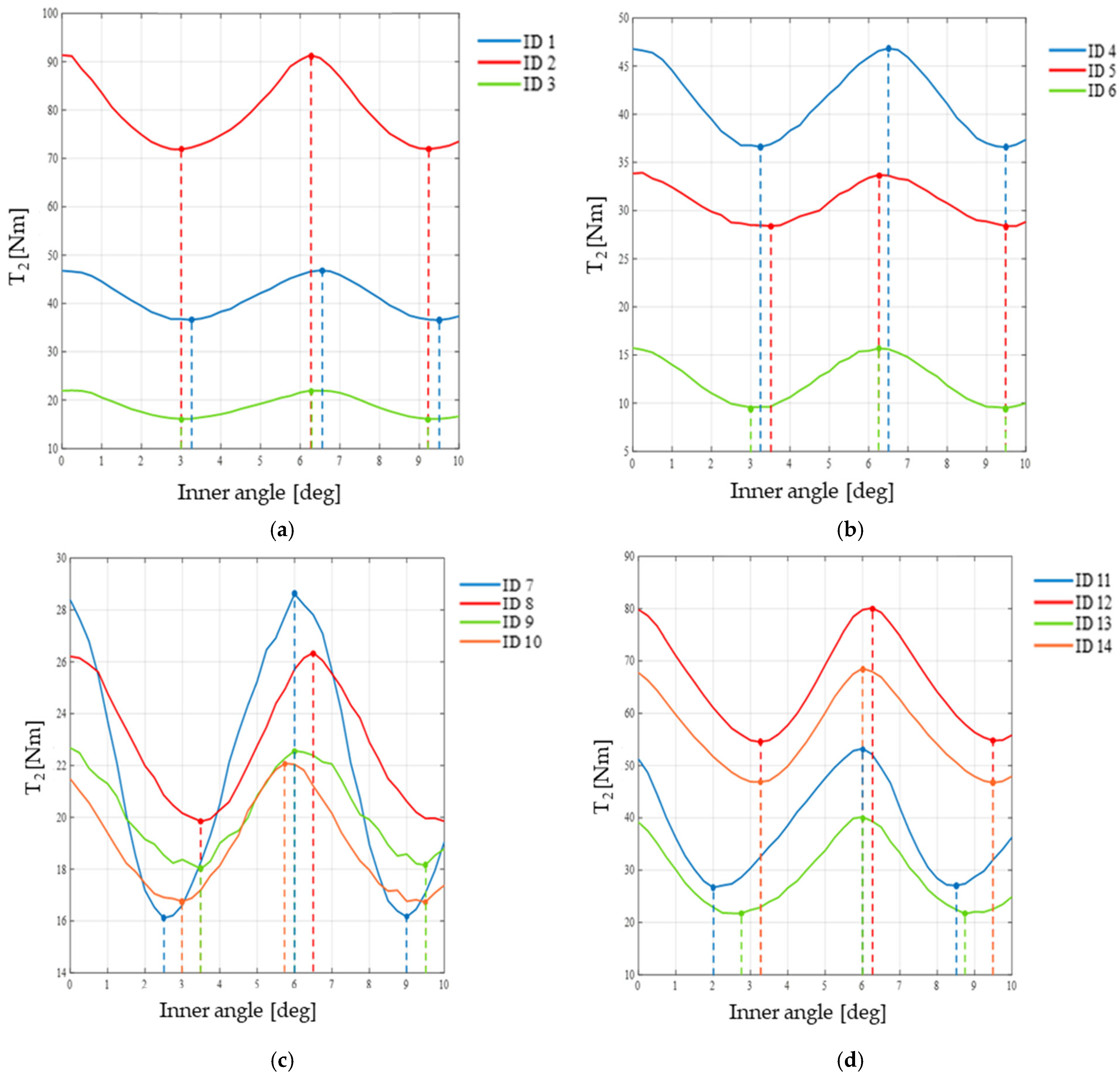
To highlight the complexity of the design space and justify the adoption of a systematic optimization approach, a parametric sensitivity analysis was conducted on fourteen representative configurations, grouped into four comparison sets (
Table 4,
Figure 7). The analysis focuses on the inner rotor torque profile, where the ripple is most pronounced and therefore most critical to the device’s performance.
Effect of radial thicknesses (
Figure 7a): Configurations 1–3 keep the fill factors constant (k
2 = k
3 = 0.5) while varying the distribution of radial thicknesses. The results show that the thicknesses primarily govern the torque amplitude: configuration 2, with an oversized inner yoke and inner rotor teeth (dr
5 = 15.19 mm, dr
6 = 10.52 mm), nearly doubles the maximum torque compared to the baseline (T
max = 91.35 Nm vs. 46.83 Nm), while maintaining a nearly unchanged percentage ripple of approximately 24%.
Configuration 3, which prioritizes modulators at the expense of permanent magnets, produces the lowest torque (Tmax = 21.94 Nm) with the highest ripple in the group (30.55%). In all three cases, the angular positions of the maximum and minimum remain substantially aligned, confirming that the distribution of thicknesses alters the amplitude of the magnetic flux but not the fundamental harmonic structure of the field.
Configurations 4–6 (
Figure 7b) explore the uniform variation in k
2 = k
3 at equal thicknesses (dr
i = 8.2 mm). Here too, substantial phase invariance is observed: the profiles of the three configurations are in phase with each other, with angular phase shifts of less than 0.25°. Reducing the fill factors (ID 5, k = 0.3) lowers the torque and ripple (Tmax = 33.69 Nm, R = 17.04%), while increasing them (ID 6, k = 0.8) further reduces the torque (Tmax = 15.69 Nm), bringing the ripple to 48.46%.
Configurations 7–10 (
Figure 7c) introduce asymmetry between k
2 (modulators) and k
3 (internal teeth), while maintaining uniform thicknesses. Unlike the previous cases, the asymmetry k
2 ≠ k
3 produces appreciable angular phase shifts in addition to amplitude variations: comparing configurations 7 (k
2 = 0.5, k
3 = 0.8) and 8 (k
2 = 0.8, k
3 = 0.5), the torque maximum shifts by 0.5° and the minimum by 1°, with ripple varying from 55.90% to 32.57%. Similarly, configurations 9 and 10 show phase shifts of up to 0.5° and a ripple difference of approximately 18%. This behavior, absent in cases with uniform factors, highlights that the asymmetry between the two factors introduces complex harmonic interactions between the spatial modulation of the modulators and the reluctance response of the internal teeth.
Configurations 11–14 (
Figure 7d) apply the same asymmetric combinations of k
2 and k
3 to the optimized thickness distribution derived in a previous work by the authors [
32], corresponding to configuration 2 and the maximum pair observed in
Figure 7a. The results reveal a nonlinear interaction between the two sets of parameters. In particular, reversing the fill factors (from k
2 = 0.5, k
3 = 0.8 to k
2 = 0.8, k
3 = 0.5) produces a 33.5% increase in torque (from T
max = 53.25 Nm to 80.10 Nm) with a simultaneous reduction in ripple from 66.45% to 37.96%, a behaviour far more pronounced than in the case of uniform thicknesses. This demonstrates that, when the magnetic circuit is unbalanced toward the inner rotor, the role of the modulators becomes predominant: favouring k
2 over k
3 results in a torque gain and a reduction in ripple that would not be predictable from a decoupled analysis of the two parameters.
Overall, the sensitivity analysis demonstrates that the design space is characterized by strong nonlinearities and interactions between parameters: radial thicknesses and fill factors produce qualitatively different effects depending on the reference configuration, rendering ineffective any optimization approach based on the sequential variation in a single parameter. These findings justify the adoption of a multi-objective genetic algorithm capable of simultaneously exploring the entire design space.
3.3. Mesh Size Selection
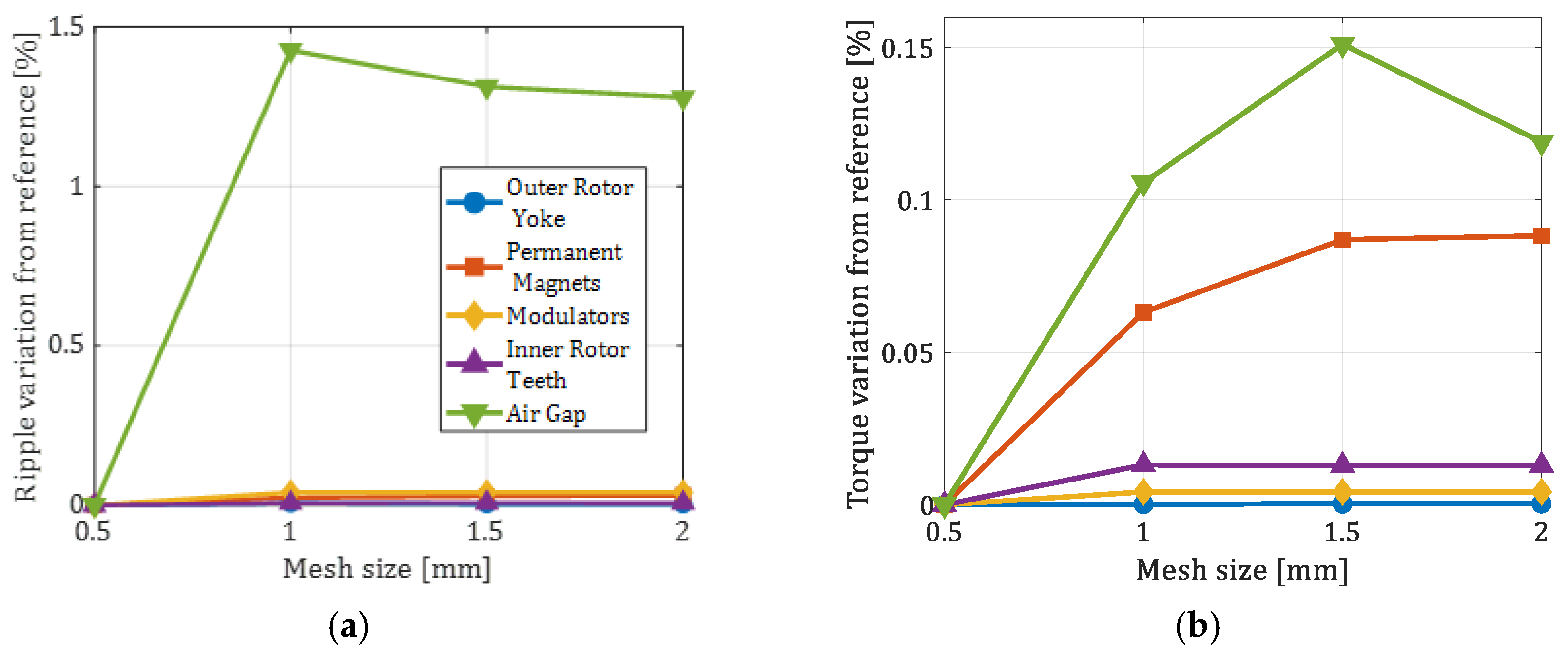
To ensure that no calculation errors occur due to an incorrect mesh size, a sensitivity analysis was also performed regarding the mesh size. Specifically, the study evaluated how both the torque ripple and the stall torque tend to change relative to a reference scenario as the mesh of individual components varies. In the case under examination, the reference configuration is that with the maximum mesh size of the components set at 0.5 mm, for a uniform distribution of thicknesses and with fill factors equal to 0.5.
Figure 8 shows the trend of the percentage variation in torque ripple (
Figure 8a) and stall torque (
Figure 8b) of the inner rotor as the mesh size varies for one element at a time.
It can be seen that, for the torque ripple (
Figure 8a), only the air gap shows an appreciable sensitivity, with a maximum variation of 1.43% at a mesh size of 1 mm; for all the other components the variation remains below 0.05% over the entire mesh range and is considered negligible. The stall torque (
Figure 8b) exhibits the same qualitative behaviour but with lower sensitivity, as expected: the air gap is again the only region exceeding 0.1% (maximum 0.15%), while all the other components stay below 0.1% and their variation is negligible. Based on these results, the maximum mesh size was set to 2 mm for all the active components and to 0.5 mm for the air gap, ensuring that the residual mesh-induced error on the ripple remains well below 0.1%, which is acceptable considering that the ripple values at the optimized configurations are of the order of 1%.
4. Multi-Objective Optimization
The objectives and geometric constraints adopted in the subsequent optimization problem reflect the practical design requirements previously outlined in
Section 1. The maximization of the average inner-rotor torque (T
avg) is imperative in addressing the necessity for a device with high torque density within the fixed external envelope reported in
Table 1. The minimization of the percentage ripple R addresses the well-known issues of vibration and acoustic noise associated with magnetic gearboxes. These issues can trigger resonance phenomena in the mechanical structure and compromise its long-term reliability. The seven design variables correspond to the manufacturable geometric parameters of the device (radial thicknesses and angular fill factors), over which the designer has direct control, while the fixed external dimensions and the 1 mm air-gap thickness represent values that are compatible with the integration constraints of the target application.
As demonstrated in the sensitivity analysis of the preceding section, the design space is characterised by intricate interactions and substantial coupling between the design variables [
32,
33], thus rendering any manual design approach ineffective. In order to address the aforementioned complexity, the optimisation problem is solved by implementing a multi-objective genetic algorithm in the gamultiobj function of MATLAB R2024b.
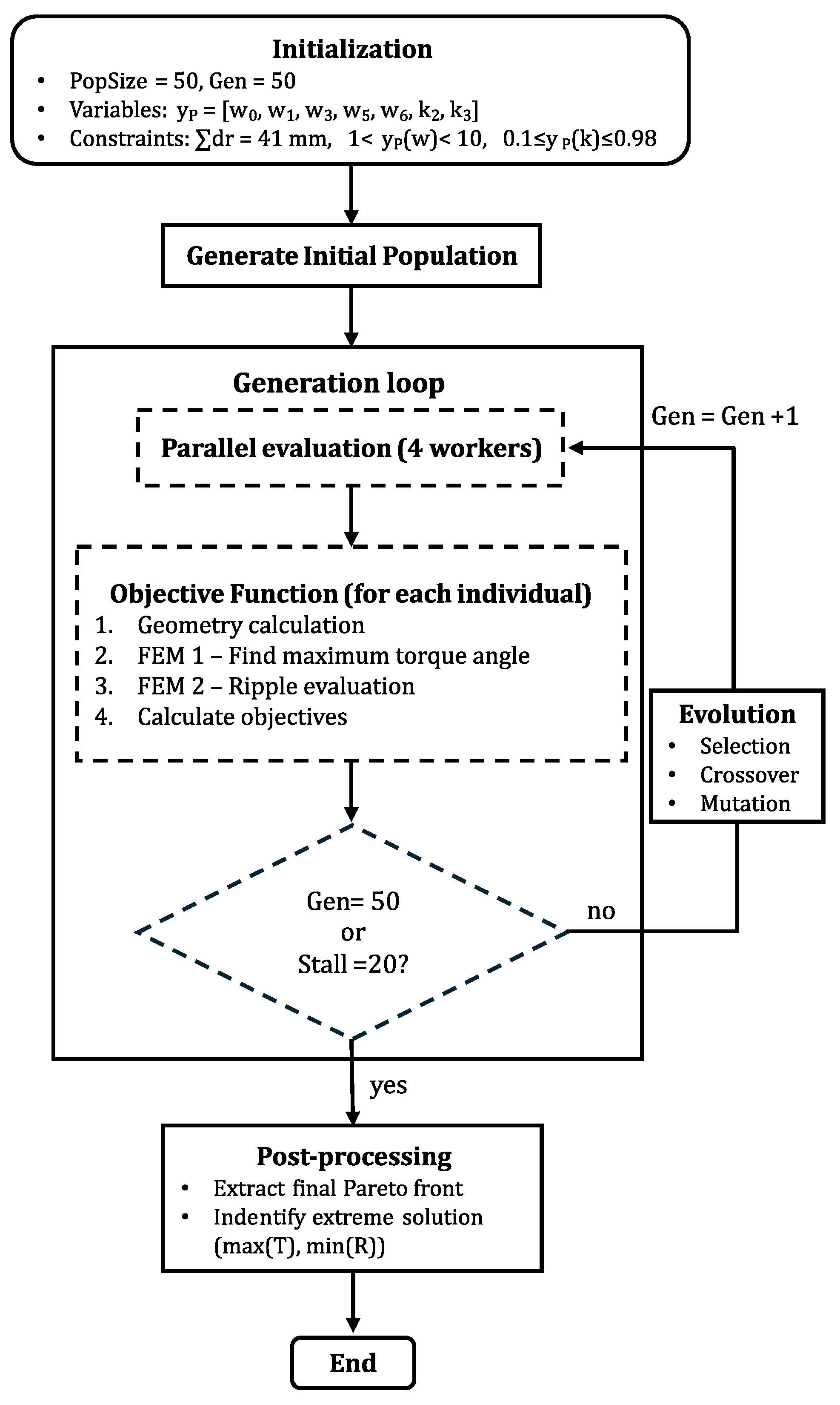
The complete algorithm flowchart is presented in
Figure 9.
Since genetic algorithms are formulated as minimization problems, the first objective is expressed as a minimization, and the mathematical formulation of the multi-objective problem is expressed as:
where T
avg is the average torque of the inner rotor and R is the percentage ripple defined by Equation (7).
The design variables are represented by the 7-dimensional vector y
P, which contains the five radial thickness weights (w
0, w
1, w
3, w
5, w
6) and the two filling factors (k
2, k
3). Therefore, this can be written as:
The problem must satisfy geometric and physical constraints: the fill factors must be restricted to the interval [0.1, 0.98] to avoid physical overlaps and numerical issues in the FEM analysis, and the sum of the radial thicknesses must equal the available radial space of 41 mm according to Equation (4). For this reason, the optimization model makes use of weights w
i that can handle this constraint, as they are related to the thicknesses by the following relationship:
where i = 0, 1, 3, 5, 6.
The algorithm operates through evolutionary cycles in which a population of candidate configurations is progressively improved using genetic operators of selection, crossover, and mutation. In each generation, the individuals are evaluated using FEM analysis.
The parameters of the genetic algorithm, shown in
Table 5, were selected by balancing the accuracy of the design space exploration with computational constraints. The population size was set to 50 individuals, a value representing a compromise between the need to adequately explore the 7-dimensional design space and sustainable computational times. The maximum number of generations was set to 50, allowing for a total of 2500 FEM evaluations distributed throughout the entire evolutionary process. The Pareto fraction, a parameter that controls the percentage of solutions retained on the Pareto front at each generation, was left at the default value of 0.35 as it ensures a good balance between conservatism and exploration. In fact, in the case under consideration, the goal is to preserve approximately 18 individuals on the Pareto front, while the remaining individuals are generated using genetic operators to maintain diversity and prevent premature convergence toward local optima.
The early termination criterion using MaxStallGenerations was set to 20 generations, halting the optimization if no improvements are observed on the Pareto front for 20 consecutive generations. This avoids unnecessary FEM evaluations once the algorithm has reached convergence, reducing the overall computational time in the event of premature convergence. The genetic operators use a crossover fraction of 0.8, which determines the percentage of individuals generated through recombination of parental solutions, while the remaining fraction is generated through random mutation to maintain genetic diversity and avoid premature convergence to local optima.
At the end of the optimization, the resulting Pareto front is analyzed to identify configurations of particular practical interest.
The optimisation runs were conducted on a standard workstation that was equipped with an Intel Xeon E3-1270 CPU (4 cores, 8 logical processors, 3.40 GHz) and 16 GB of RAM. In order to perform the parallel evaluation of the GA population, four MATLAB workers were utilised. The mean elapsed clock time for one complete GRint optimization cycle (50 generations × 50 individuals) was approximately 6388 min (i.e., 106 h). This corresponds to approximately 2.6 min per individual in parallel (i.e., approximately 10 min on a single core). The cost is dominated by the FEM analyses and scales linearly with the total number of evaluations, meaning that the present approach remains tractable on a standard multi-core machine without requiring high-performance computing resources. It is evident that the incorporation of a greater number of design variables would not result in an escalation of the cost per FEM evaluation. However, it is customary for such an expansion to necessitate a more substantial population and an augmented number of generations to adequately explore the higher-dimensional design space. This, in turn, would engender a proportional increase in the total runtime.
5. Results and Discussion
The multi-objective genetic algorithm was applied to four configurations of the magnetic gearbox, corresponding to GR
int = 4, 5, 6, and 7, while keeping the number of teeth on the inner rotor n
3 = 5 fixed. For each configuration, 50 generations were run with a population of 50 individuals, simultaneously optimizing the average torque of the inner rotor T
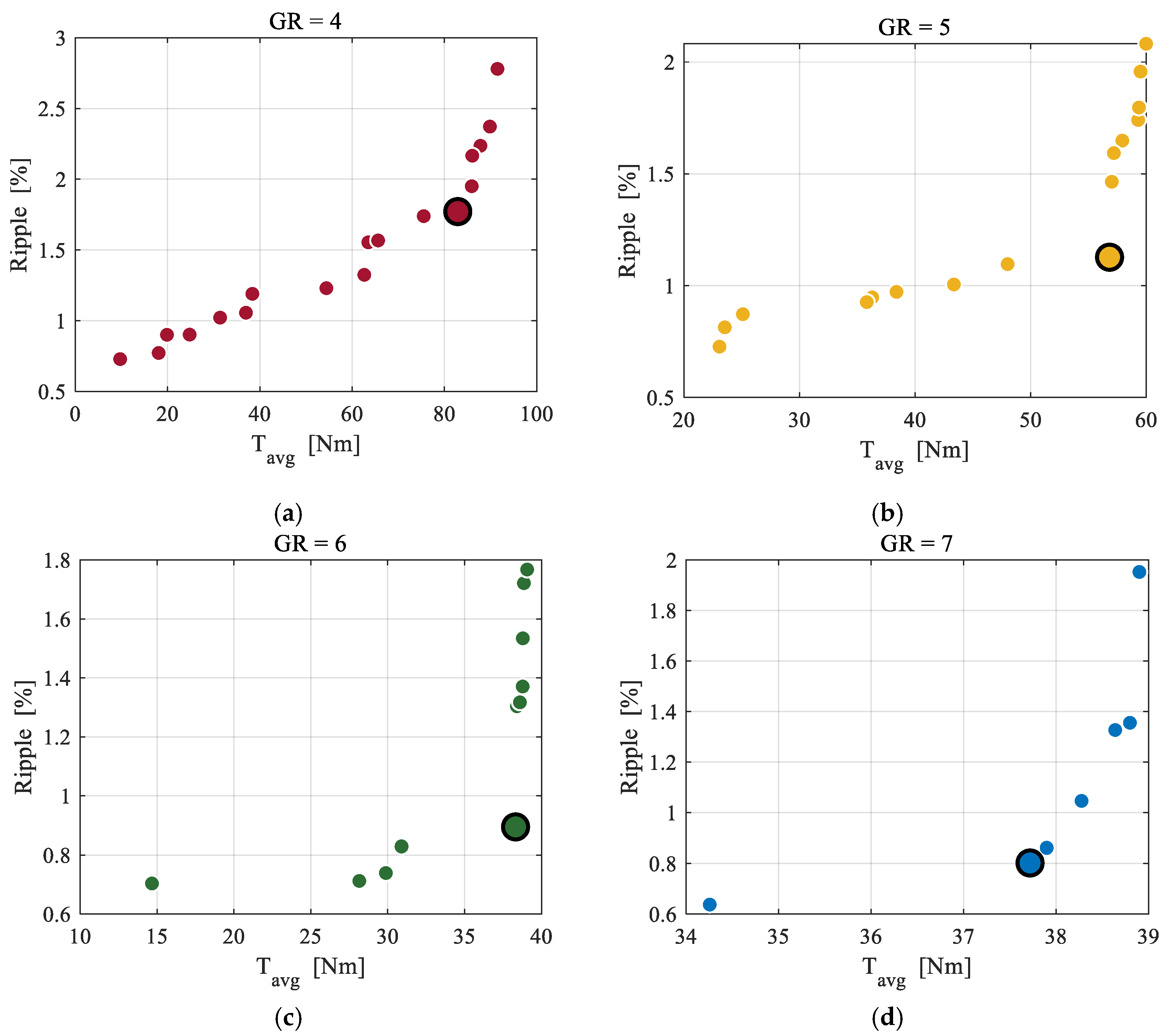
avg and the percentage ripple. The resulting Pareto fronts, shown in
Figure 10, describe the set of non-dominated solutions for each GR and make explicit the trade-off between the two objective measures.
An immediate observation concerns the effect of the gear ratio on the maximum achievable torque: GR = 4 yields the front with the highest torques, with Tavg up to 91.50 Nm, while GR = 6 and GR = 7 settle at significantly lower values, 39.07 Nm and 38.90 Nm, respectively. GR = 5 occupies an intermediate position with a maximum value of Tavg = 59.99 Nm. As for minimum ripple, the four GRs show comparable and very low values, ranging from 0.64% (GR = 7) to 0.73% (GR = 4 and GR = 5), confirming that in all configurations the algorithm is capable of identifying low-ripple solutions. The cost of this minimization is, however, different: for GR = 7, the torque at the minimum-ripple solution remains high (34.26 Nm), while for GR = 6 it drops to 14.67 Nm, indicating a more penalizing trade-off.
The shape of the Pareto fronts is also informative. GR = 7 and GR = 6 show relatively compact fronts, with a limited variation in Tavg as ripple increases, suggesting that for these values of GR, the space of undominated solutions is less extensive. In particular, the Pareto front for GR = 7 features a small number of non-dominated solutions concentrated within a narrow range of average torque (ΔTavg ≈ 5 Nm), indicating that the algorithm has almost completely explored the optimal region achievable for this configuration. In contrast, GR = 4 exhibits a wider front, with a wide range of torque (from ~10 Nm to ~91 Nm) compared to a ripple range that widens up to approximately 2.80%, indicating greater sensitivity of the configuration to position on the front.
Given the multi-objective nature of the optimization, the balanced solution—obtained by assigning equal weights to the two objectives—is adopted as the reference solution for comparing the different GR configurations. The corresponding values are shown in
Table 6. GR = 4 offers the highest balanced torque (85.93 Nm) but with the highest ripple among the reference solutions (1.95%), while GR = 7 provides the smoothest solution (37.72 Nm, ripple 0.80%). GR = 5 represents a good compromise in absolute terms, with 56.83 Nm and 1.13% ripple.
5.1. Convergence and Robustness Analysis
In order to verify the suitability of the GA parameters shown in
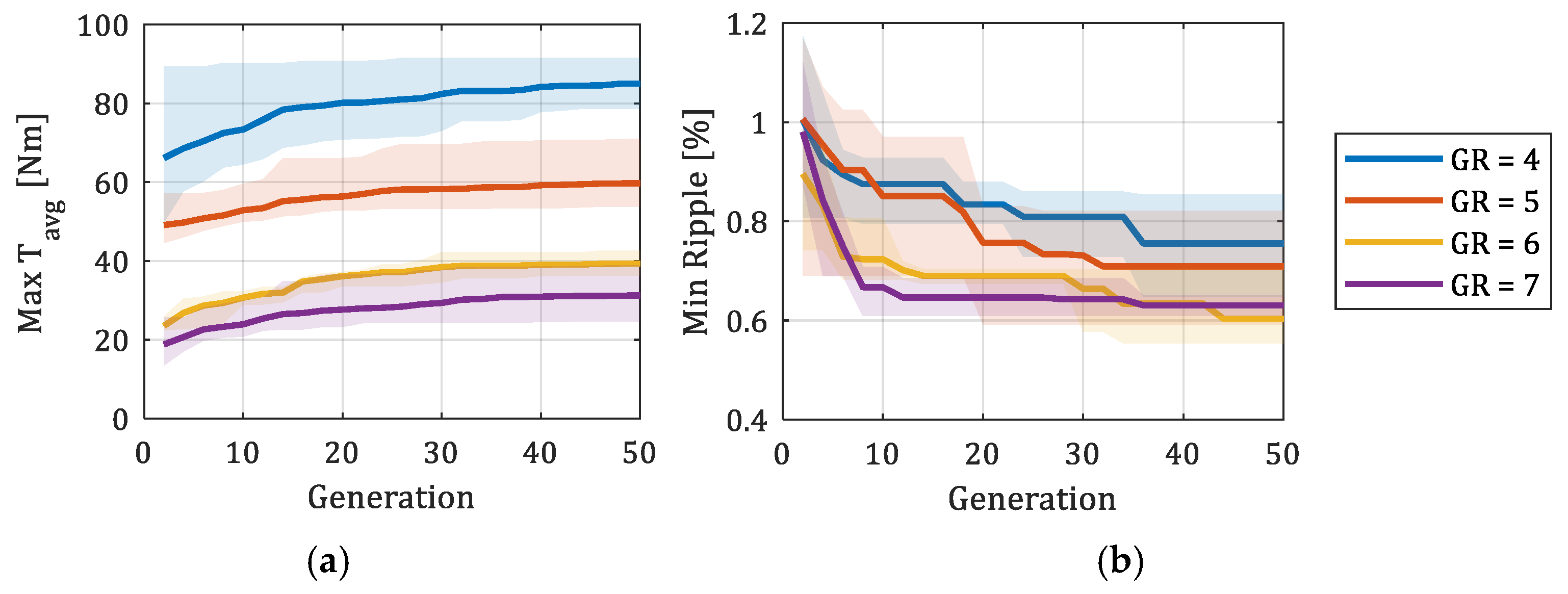
Table 5 and to rule out convergence to local optima, four independent runs with different random seeds were performed for each GR configuration. As illustrated in
Figure 11, the convergence trace of the maximum T
avg (a) and the minimum ripple (b) of the accumulated Pareto front is presented as a function of generation. The shaded bands represent the min–max envelope across the four runs. For all GR values, both indicators attain a plateau well before generation 50, thereby confirming that 50 generations are sufficient to obtain a stable Pareto front and that further iterations would not yield significant improvements. As the algorithm progresses, the shaded bands undergo a narrowing progression, a phenomenon that does not culminate in a collapse to zero, particularly for GR = 5 and GR = 7.
In
Table 6 the dispersion of the balanced solutions over the four runs is summarised. The coefficient of variation (CV = σ/μ × 100) on T
avg ranges from 5.1% (GR = 6) to 23.1% (GR = 7), and on the ripple from 8.3% (GR = 5) to 25.3% (GR = 7). In the cases of GR = 5 and GR = 6, the four Pareto fronts are found to be largely congruent, with the dispersion of the balanced point along the front being the sole contributing factor. For GR = 4 and GR = 7, the bands depicted in
Figure 11 maintain their width throughout the plateau, thereby suggesting that not all runs attain the same Pareto-optimal region. Specifically, for GR = 4, one of the runs converges to a sub-optimal branch characterised by an oversized outer yoke and a reduced maximum torque (approximately 62 Nm as opposed to approximately 85 Nm observed in the other runs). For GR = 7, the absolute spread of T
avg, while comparable to that of GR = 5, is amplified in relative terms by the diminished mean value. In all cases, the qualitative outcome of the optimisation is preserved across runs (inner-rotor dominance and modulators as the thinnest layer).
5.2. Distribution of Geometric Parameters
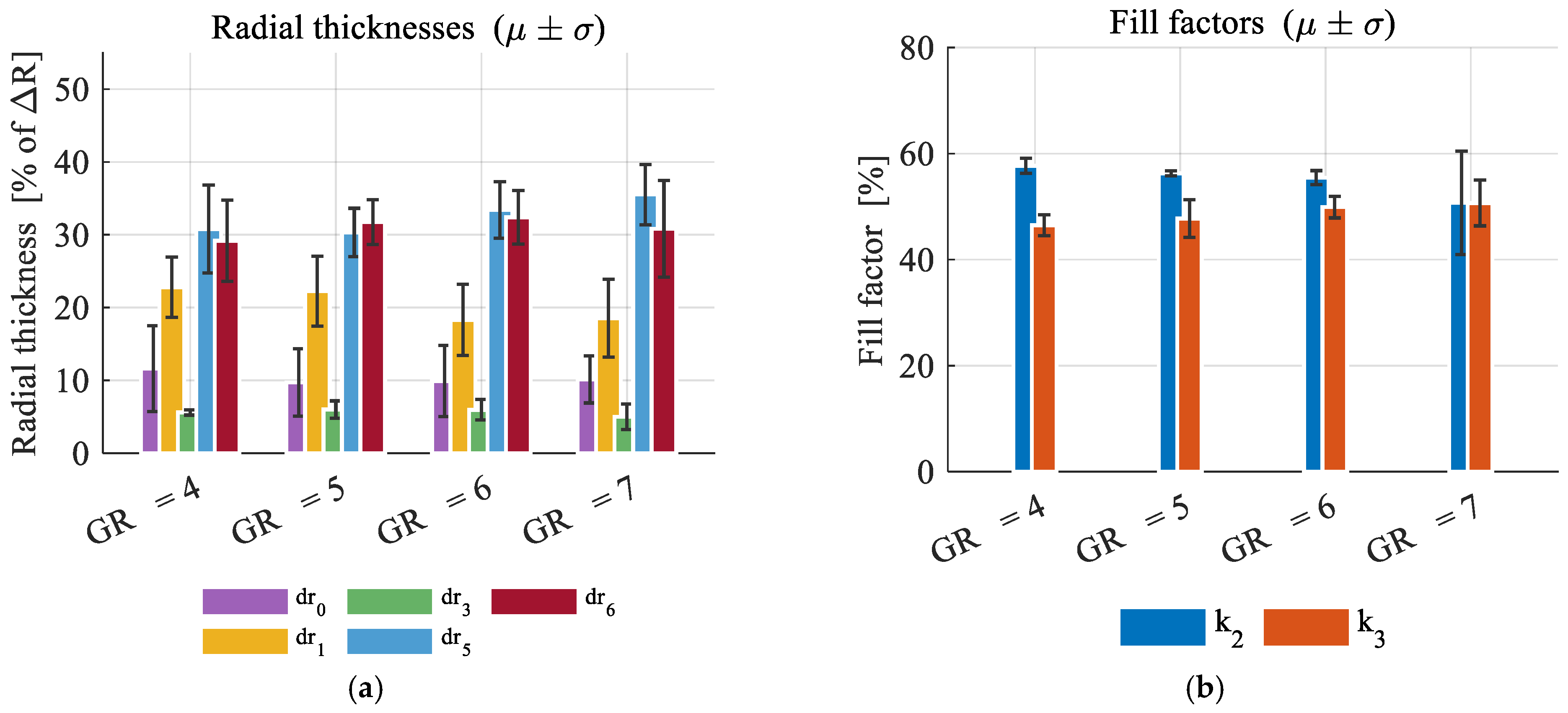
As illustrated in
Figure 12, the mean values ± standard deviation of the radial thicknesses (a) and the fill factors (b) at the balanced solution for each GR are reported. The geometric allocation exhibits robustness across runs and is consistent across all configurations. The algorithm concentrates the majority of the available radial span in the inner rotor (dr
5 + dr
6), with a mean share ranging from approximately 60% at GR = 4 to 66.3% at GR = 7, exhibiting a mild increasing trend. Within this allocation, the inner-rotor teeth (dr
5) and the inner yoke (dr
6) occupy comparable fractions of the order of 30% each, the modulators (dr
3) consistently represent the thinnest layer (~5–6%), the outer rotor yoke (dr
0) is also kept thin (~10%), and the permanent magnets (dr
1) account for the remaining 18.3–22.8% with the largest run-to-run variability.
The fill factor k
3 of the inner rotor (
Figure 12b) remains largely constant across various configurations, with a mean ranging from 46.5% to 50.7% and a coefficient of variation (CV) consistently below 9%. This suggests that its optimal value is largely independent of the gear ratio. The fill factor k
2 of the modulators exhibited a modest decline with GR, ranging from 57.7% at GR = 4 to 50.7% at GR = 7, representing a seven-percentage-point variation across the examined range.
The recurrence of this pattern, at least for low values of n
3, is supported by the authors’ previous single-objective work [
34], in which the same RMG topology was optimised with n
3 = 3 to maximise the peak torque rather than the average torque and the ripple. Despite the differing n
3 and differing optimisation objectives, the optimal radial allocation reported in [
34] exhibits the same qualitative features observed here: inner-rotor dominance (62.7% in [
34] vs. 60–66% in the present work), modulators as the thinnest layer (about 5%), thin outer yoke (~9%), and permanent magnets around 23%. The extension to substantially higher pole counts (e.g., n
3 = 10 or 15) is not addressed here, since the small device dimensions reported in
Table 1 limit the practical feasibility of such configurations. A substantial increase in n
3 would proportionally increase the number of modulators (Equations (2) and (3)), with widths potentially incompatible with both manufacturing and FEM-modelling constraints.
5.3. Flux Density Distribution
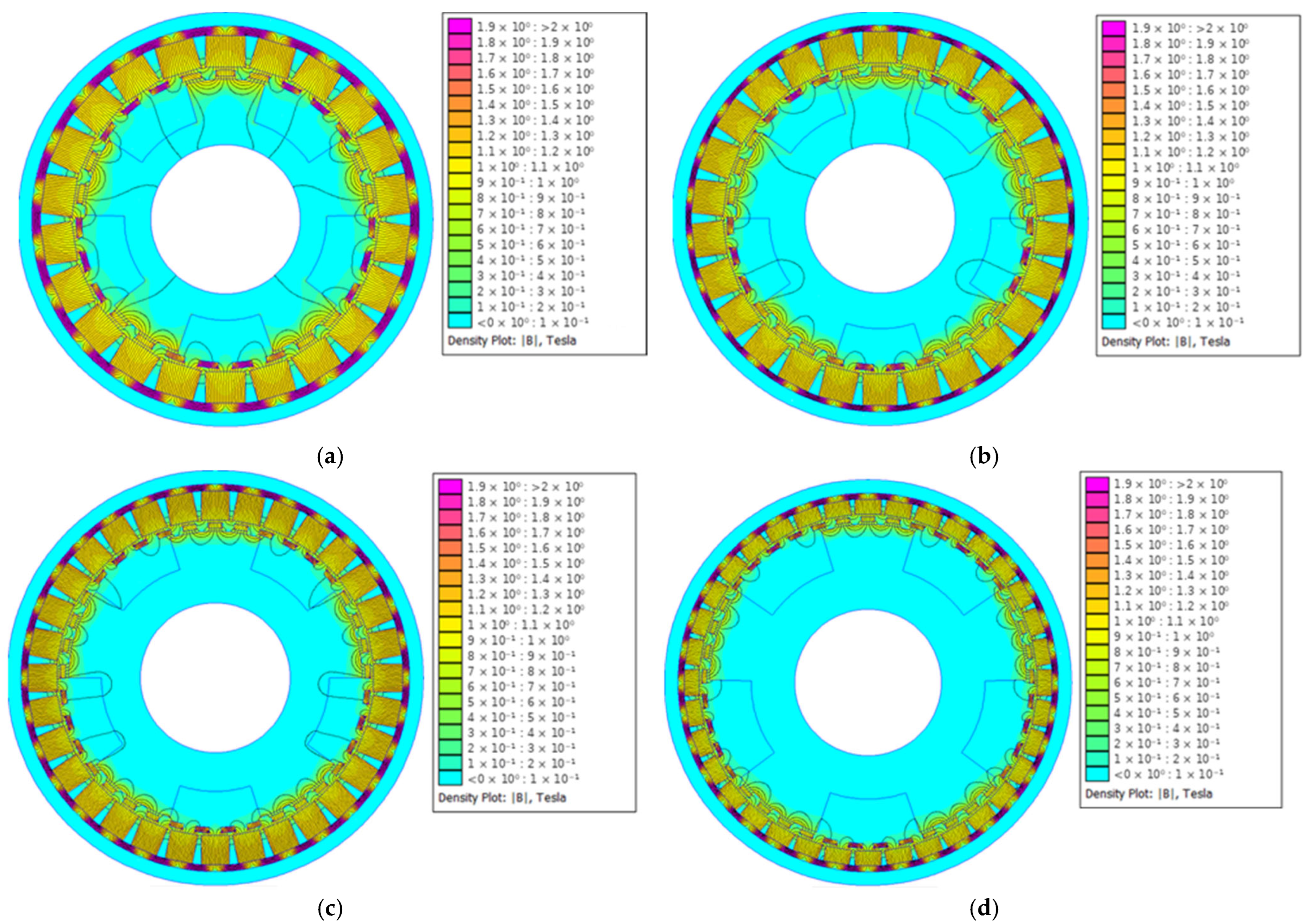
The magnetic flux density distributions reported in
Figure 13 and
Table 7 refer to the optimal configuration identified across the four independent runs conducted for each GR. The selection criterion is the weighted figure of merit, F, which is defined as:
Here, max(T
avg) and max(R
max) are the maximum values observed across the four runs at the same GR. The run with the highest F is taken as representative. According to this criterion, the representative configuration is Run 2 for GR = 4 (T
avg = 77.07 Nm, R = 1.63%) and Run 1 for GR = 5, 6 and 7 (T
avg = 56.83, 38.32 and 37.72 Nm, with R = 1.13%, 0.89% and 0.80% respectively). It should be noted that these configurations represent the best compromise found among the cases examined in this study and do not represent the global optimum in absolute terms. The corresponding radial allocations and fill factors are reported in
Table 8.
It is immediately apparent that, for all configurations, the inner rotor exhibits a very low flux density, indicating that it is underutilized. Similarly, it can be observed that for the modulators, material saturation occurs in all modulators at the tooth gaps, where there is a clear accumulation of flux that cannot be dissipated onto the inner rotor. The most severe saturation of the modulators occurs for GRint = 4.
The outer rotor iron represents the region with the most severe saturation of all for all GRs examined. In fact, the outer rotor iron does not contribute to improving torque or reducing ripple based on the optimization results, but minimizing the thickness to such an extent results in excessive saturation with associated losses. In this case, the configuration with the highest flux density is the one with GR = 5.
Like the inner rotor yoke, the teeth are also very lightly “loaded”. The highest B values can be seen at the tips of the teeth, where saturation is far from being reached in any case, since in the worst-case scenario it reaches up to 1.28 T for GR = 4.
Generally, one might note that for GR 6 and 7, the flux density concentrations are lower, although the saturation value is exceeded here as well, even in this case for the modulators and the outer rotor yoke. Similarly, for the same configurations, the inner rotor has the lowest maximum magnetic flux density.
The observed flux density distribution asymmetry, with low B values in the inner rotor and saturation in the outer yoke and modulators, can be attributed to a topological feature of the RMG configuration. The flux produced by the PMs must close through the outer yoke and pass through the modulators, which tend to be stressed when the algorithm minimises their thickness. Torque transmission to the inner rotor is mainly sustained by the modulators, and the remaining harmonic content couples weakly to the inner rotor. The flux-density asymmetry can therefore be interpreted as a feature of the reluctance topology, with a magnitude depending on the geometric proportions selected by the optimization.
In a practical implementation, the saturation levels in the outer rotor yoke and modulators, both well above the 2.0–2.2 T saturation level of M270-35A electrical steel, would imply substantial iron losses and consequent thermal heating. The flux density distributions reported here are therefore representative of the geometric allocation pattern produced by the unconstrained optimization, and the absolute B values are not intended to represent the design of a thermally and mechanically realisable RMG. The introduction of an explicit constraint on the maximum flux density in the saturated regions, possibly coupled with a thermal-loss analysis, is acknowledged as a direction for future work.
6. Conclusions
In this work, a multi-objective optimization based on a genetic algorithm was applied to four configurations of a concentric magnetic reducer, with gear ratios GRint = 4, 5, 6, and 7, simultaneously optimizing the average torque of the inner rotor and the percentage ripple. The results obtained allow for some general conclusions to be drawn.
The multi-objective formulation produces a Pareto front for each GR (
Figure 10), along which solutions with substantially different torque/ripple compromises can be selected. The balanced solutions demonstrate that low-ripple configurations are attainable for all GR values, albeit with a modest decline in T
avg.
The optimisation results reveal a geometric allocation pattern that is robust across the four GR values. The convergence and multi-run analysis presented in
Section 5.1 demonstrates that the algorithm attains a stable Pareto front before generation 50. Furthermore, the qualitative geometric features—inner-rotor dominance (~60% of Δr), modulators as the thinnest layer (~5%), thin outer rotor yoke (~10%), permanent magnets occupying a stable share around 22%, and inner-rotor fill factor close to 0.5—are preserved across independent runs.
The flux density analysis reveals that, in the absence of an explicit constraint on B, the optimization saturates the modulators and the outer rotor yoke beyond the saturation level of conventional electrical steel, while the inner rotor remains under-utilized. In a practical implementation, such saturated regions would translate into substantial iron losses and thermal heating. The conclusions previously discussed are thus contingent on the qualitative geometric allocation pattern that emerges from the optimisation process. The absolute values of B are not a contributing factor in these conclusions. The introduction of an explicit constraint on the maximum flux density in the critical regions, potentially in conjunction with a thermal-loss analysis, is a subject to be addressed in future research.




 ,
,