1. Introduction
Driven by global energy policies aimed at mitigating climate change, the transition to renewable energies, involving a gradual exclusion of fossil fuels and their replacement by low-emission technologies, is fundamental. In this scenario, the increase in the production of renewable energy is a necessary trajectory.
Among the available solutions for producing electricity by means of renewable sources, photovoltaic technology (PV) and wind energy (WE) are expected to play a major role in the future energy mix. Their maturity and reliability are now well assessed, and the cost of the electricity produced is comparable to—and even lower than—the cost of fossil electricity [
1]. The main drawback of PV and WE technologies is the intermittency in the electricity generation that follows the instantaneous availability of the energy source (sun irradiation or wind intensity). For this reason, they are referred to as Variable Renewable Energies (VREs). Therefore, energy storage systems are crucial for achieving a high VRE penetration in the energy market. Since both PV and WE directly produce electricity, a suitable storage system should be efficiently chargeable by electrical energy.
Despite their distinct technologies, PV and wind energy share two key aspects: (i) they produce direct electrical energy and (ii) the intermittent production follows the instantaneous availability of the energy source (sun irradiation or wind intensity). Consequently, they are commonly referred to as Variable Renewable Energy (VRE). From (ii), it is evident that storage systems will be crucial for high VRE penetration in the energy market, whereas, from (i), it can be inferred that VRE storage requires systems that are efficiently chargeable by electrical energy.
For small-scale storage applications, electrochemical batteries appear to be a straightforward solution; however, batteries become less competitive for storages above a few hours of production [
2,
3]. Furthermore, for large-scale storages, such as systems designed to supply energy over days or weeks to compensate for prolonged periods of low production or even seasonal variation, batteries are not a suitable option. Carnot batteries offer a potential alternative to electrochemical batteries by converting electrical energy into economically storable thermal energy, which is then reconverted to electricity, with an overall efficiency exceeding 50% [
4].
A widely studied type of high-temperature thermal storage uses a molten salt mixture [
5] of nitrates (NaNO
3/KNO
3, 60/40%wt), known as Solar Salt, as a storage medium. This system exploits the sensible heat stored by the salt within a temperature range from slightly above its liquidus temperature (cold) to slightly below its decomposition temperature (hot). Usually, the operating temperature range is comprised between 270 °C and 565 °C. The storage can be implemented as either a two-tank or as a single-tank thermocline system. Molten salt (MS) storage, initially developed for concentrated solar thermal electricity generation, shows significant potential for heat generation in endothermic industrial processes [
6].
In some applications, MS storage was configured as a passive system, receiving heat from the heat transfer fluid via heat exchangers [
7]; in other applications, molten salt was also used as heat transfer fluid, circulating in the solar receivers [
8,
9,
10,
11]. The use of molten salt storages to accumulate electrical energy has been explored for hybrid non-compact PV/thermal plants, where two solar fields—one of concentrating thermal collectors, one of PV—share the same thermal storage [
12,
13]. The impact of different electric (Joule-based) heater placements on the performance of an MS two-tank storage system has been investigated in the study of [
14].
In summary, driven by the need for storage systems with capacities beyond those of electrical batteries, current research is focusing on thermal energy storages, specifically Solar Salt-based storage units, drawing upon solar thermal expertise and aiming at straightforward integration with established solar thermal facilities. However, another aspect and relevant parameter—beside the sheer capacity—that should be considered when assessing the feasibility of such a storage is the maximum power that can be transferred to the thermal storage without degrading the storage medium or compromising the safety of the plant. This maximum power depends on the heat transfer mechanisms established in the storage system. An effective storage should be flexible in terms of admittable power discharged to the medium to follow abrupt variations in VRE generation.
This paper presents a discussion of the electric-to-heat transformation within a one-tank single-medium (Solar Salt) thermocline thermal storage system. While resistive elements (Joule heating) are the straightforward solution, they inherently impose a power limit: the transferable power diminishes to zero as the bulk storage temperature approaches its maximum, i.e., when the storage is nearly full.
An alternative volumetric heating mechanism has been recently proposed [
15,
16], based on the use of microwaves: since molten salts consist of electric dipoles, they can absorb microwaves, enabling the use of a waveguide to transmit microwaves directly in the salt mass. Such a heating system would overcome the power limitations arising from the surface heating and can work at full power—at least in principle—up to the maximum working temperature of the salt. A feasibility study of such a heating system is here performed. The novel concept of single-medium thermocline thermal energy storage with an integrated microwave heating device is presented and numerically tested both from a thermal-fluid-dynamic and electromagnetic point of view.
2. Molten Salt Properties
The salt mixture NaNO
3/KNO
3, 60/40%wt (corresponding to 64.08/35.92%mol), also known as “Solar Salt”, is extensively studied and widely used in solar engineering, given the low cost of the components, the high-temperature stability, and reduced risks compared to, for example, flammable oils or substances that are unstable in air.
Table 1 summarizes the main physical properties of the mixture that are implemented in the numerical models adopted in this work.
In the hypothesis of working between 270 °C and 565 °C, the specific storage capacity of the salt can be easily computed from the specific heat, obtaining the following:
Two main drawbacks arising from the use of Solar Salt should be pointed out. The first is the high liquidus temperature, which poses the risk of freezing and causes an unavoidable thermal loss even when the storage is “empty”, since the temperature must be kept well above the liquidus temperature. Second, of specific relevance to the subsequent discussion, is the degradation of nitrates to nitrites at high temperatures, which limits the local operating temperature to a maximum of 565 °C. This temperature restriction has consequences on energy transfer efficiency, as will be discussed in the next section.
As above mentioned, two main storage configurations exploiting molten salts have been proposed and tested:
Two-tank storage [
18]: This is the simplest and most reliable solution, with a hot tank maintained at the maximum working temperature and a cold tank at the minimum. In the charging phase, salt flows from the cold tank, is heated by the energy source, and is stored in the hot tank. In the discharging phase, salt flows from the hot tank, feeds the power generator, and then is sent back to the cold tank. The system’s primary advantage is its simplicity and manageability, while its main drawback is the need for two tanks and a salt circulation system.
Thermocline storage [
19,
20]: This is a thermal energy storage system that uses a single tank to store both hot and cold fluids, relying on thermal stratification to separate them. In the charging phase, heat is supplied to the lower, colder strata of the salt; conversely, in the discharging phase, heat is extracted from the upper, hotter salt. The implementation of specific techniques may be necessary to preserve effective stratification.
For the subsequent analysis, a single-tank thermocline storage will be used as a reference, since it allows the direct heating of the salt within the tank, offering a compact and potentially economical storage solution.
3. Joule Heating: Power Limitations
A straightforward method to store electrical energy in molten salt thermal storages is the salt heating via Joule effect, i.e., the use of heating resistances immersed in the salt. Electrical energy is dissipated into thermal energy in the resistance, governed by the following established relation:
where
W is the thermal power,
R is the resistance, and
I is the electric current in the heating resistance. The formula is valid for alternating current too, if
I is the effective current (
for a sinusoidal current, and the circuit reactance is negligible. The heat is then transferred to the salt via conduction/convection.
The system is very simple, capable of operating at nearly 100% efficiency. However, as anticipated, such a system can suffer limitations regarding the maximum power transferable to the storage. The limitations are not specific to Joule heating, but they are common to all the heating where the heat transfer to the salt occurs through contact with a heating element.
This section analyzes the heating mechanism and its limitations. The following symbols will be used in subsequent equations:
D = Diameter of the heating element;
h = Thermal transfer coefficient;
k = Thermal conductivity of salt;
cp = Specific heat of salt;
μ = Viscosity of salt;
g = Gravity acceleration (9.8 m/s2);
β = Thermal expansion coefficient of salt;
ΔT = Difference between the wall temperature of the heating element and the bulk temperature of the salt;
ρ = Salt density.
All the abovementioned parameters can be retrieved from
Table 1, except for the diameter
D, which depends on the specific system. The thermal expansion coefficient is obtained by the following formula:
The heat transport from a heating resistance to salts can be described using natural convection correlations for a horizontal cylinder in a fluid [
21]:
where
Nu,
Pr, and
Ra are the Nusselt, Prandtl, and Rayleigh numbers, respectively, and are defined as follows:
The given relations allow to calculate the heat transfer coefficient
h and, consequently, the heating power
w for unit length of the heating element:
The critical aspect of such a heat transfer mechanism is that the wall temperature of the heating element cannot exceed the maximum working temperature of the salt, since the salt in contact with the wall locally reaches the same temperature of the wall. Therefore, given a salt bulk temperature
Tbulk, the maximum transferable power for length unit is as follows:
It is worth noticing that h also depends on Tbulk, resulting in a non-linear relation with Tbulk.
It is clear from Equation (7) that wmax goes to 0 as Tbulk approaches its upper limit.
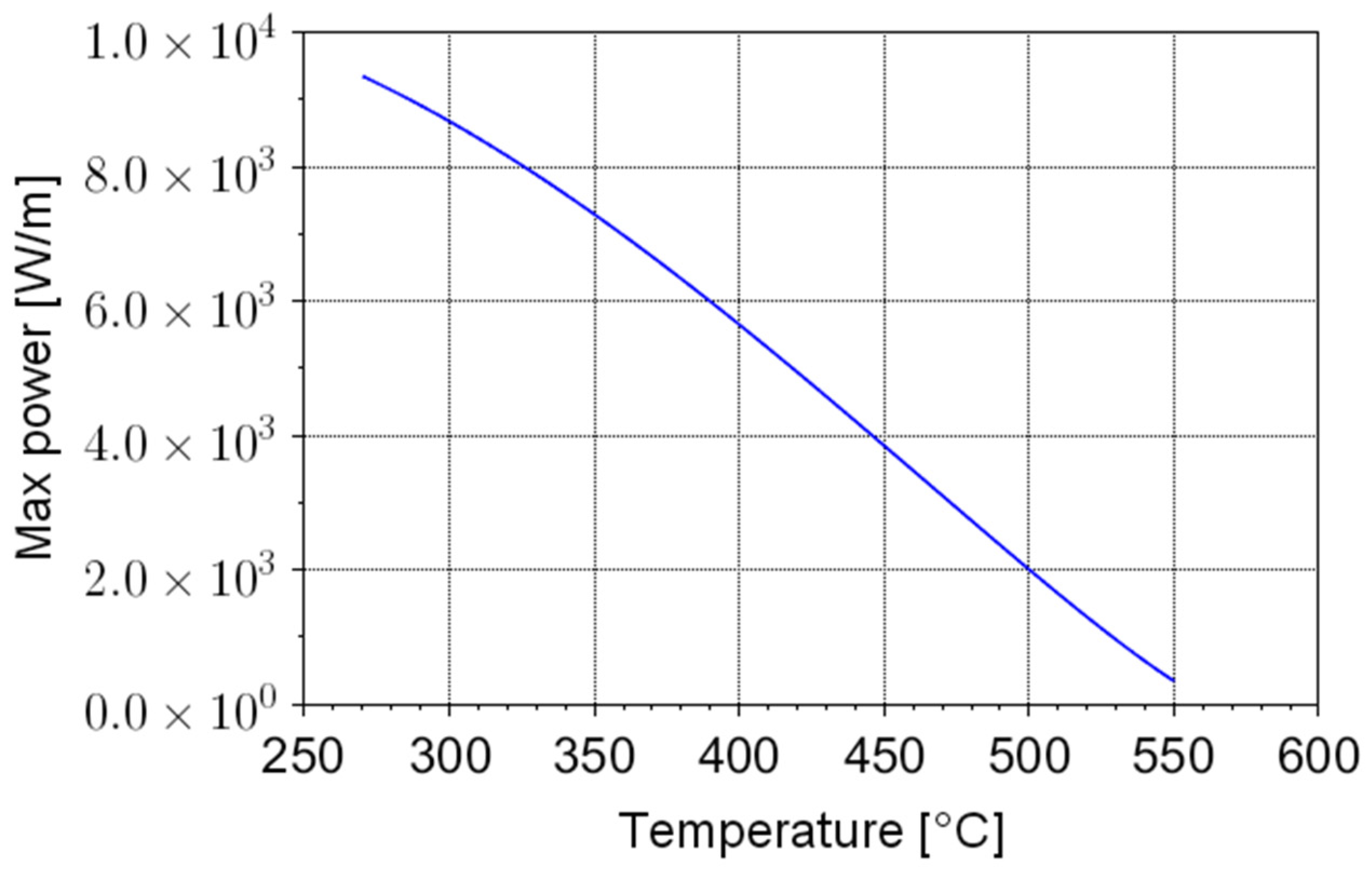
To discuss the impact of such limitation, a specific case can be considered, adopting a 1 cm diameter heating element. The dependence of
wmax from
Tbulk is shown in
Figure 1.
From
Figure 1, it is evident that the maximum power is above 9 kW/m for “cold” salt (
Tbulk = 270 °C), but it falls to 300 W/m for salt at 550 °C. Considering, e.g., a PV field with a peak power of 1 MW (around 1 ha of terrain), a few kilometers of heating elements should be placed in the storage in order to efficiently release power at
Tbulk = 550 °C. For overnight operation, a storage capacity of 3 MWh (3 h of peak power) is reasonable. Based on the salt’s specific storage capacity (Equation (1)) and density, this corresponds to an estimated volume of salts equal to 11–12 m
3. In such a volume, kilometers of heating elements should be placed—a clearly impractical (and very expensive) solution.
This simple example shows that the power limitation of Joule heating can be a practical concern for molten salt storage systems if electrical energy is the main input source. Joule heating can be effective only for salt heating up to 400 °C, whereas other non-electric power sources are required to increase the temperature further. Therefore, Joule heating can be considered an acceptable solution if the electrical heating is expected to supply a minor part of the storage charge (e.g., in hybrid plants where the storage is mainly fed by thermal plants) but not for plants where wind and PV energy is the main contributor.
4. Microwave Heating
The previous section discussed the Joule heating power limitations, which arise from surface-based heat transfer via conduction and convection. Volumetric heating offers a potential solution to this limitation. Given that molten salts consist of electric dipoles, the use of microwave energy represents a promising approach for efficient volumetric heating.
Microwave heating is widely exploited, both at the domestical and industrial level. Microwave heating is effective with electrical conductors that interact with microwaves. However, excessively high conductivity leads to shallow absorption and a significant reflection of microwaves, limiting volumetric heating.
For non-magnetic materials, the feasibility of microwave heating is primarily determined by the real (ε′) and imaginary (ε″) parts of the relative dielectric constant. The local absorption of energy for the volume unit is due to the imaginary part
ε″, or loss factor, and is given by the following equation:
where
ν is the frequency of the microwaves,
ε0 is the vacuum dielectric constant, and
Eavg is the root of the average of the square of the electric field (for a sinusoidal wave,
). The penetration depth of the microwaves in a medium is defined as the depth at which the power density of the wave is reduced by a factor 1/
e (around 37%), and is given by the following:
where
λ0 is the wavelength of the microwaves.
The loss factor
ε″ is directly related to the conductivity
σ of the medium, as follows:
However, it is important to note that the conductivity relevant to microwave heating is the effective conductivity at the microwave frequency, which can significantly differ from static conductivity.
In the case of molten Solar Salts, unfortunately, only a few experimental data on the dielectric properties at microwave frequencies are available in the literature, to the authors’ knowledge. The static conductivity (around 1 ohm
−1 cm
−1) is not indicative; it would also be too high for an effective penetration of microwaves in the salt bulk (the penetration depth
δw would be a few mm only). Temperature-dependent correlations for the real and imaginary part of the relative dielectric constant can be found in the study of [
22], based on measurements described in the study of [
15] at the standard microwave frequency (2450 MHz). However, in the study of [
15], the valid measurements do not extend to the full range of operative temperatures, and extrapolation is required. The correlations in the study of [
22] are reported below, where
T is expressed in °C:
The expression for ε″ corresponds to a conductivity that is 2–3 orders of magnitude lower than the static conductivity. The estimated penetration depth at working temperatures is in the range 10–20 cm.
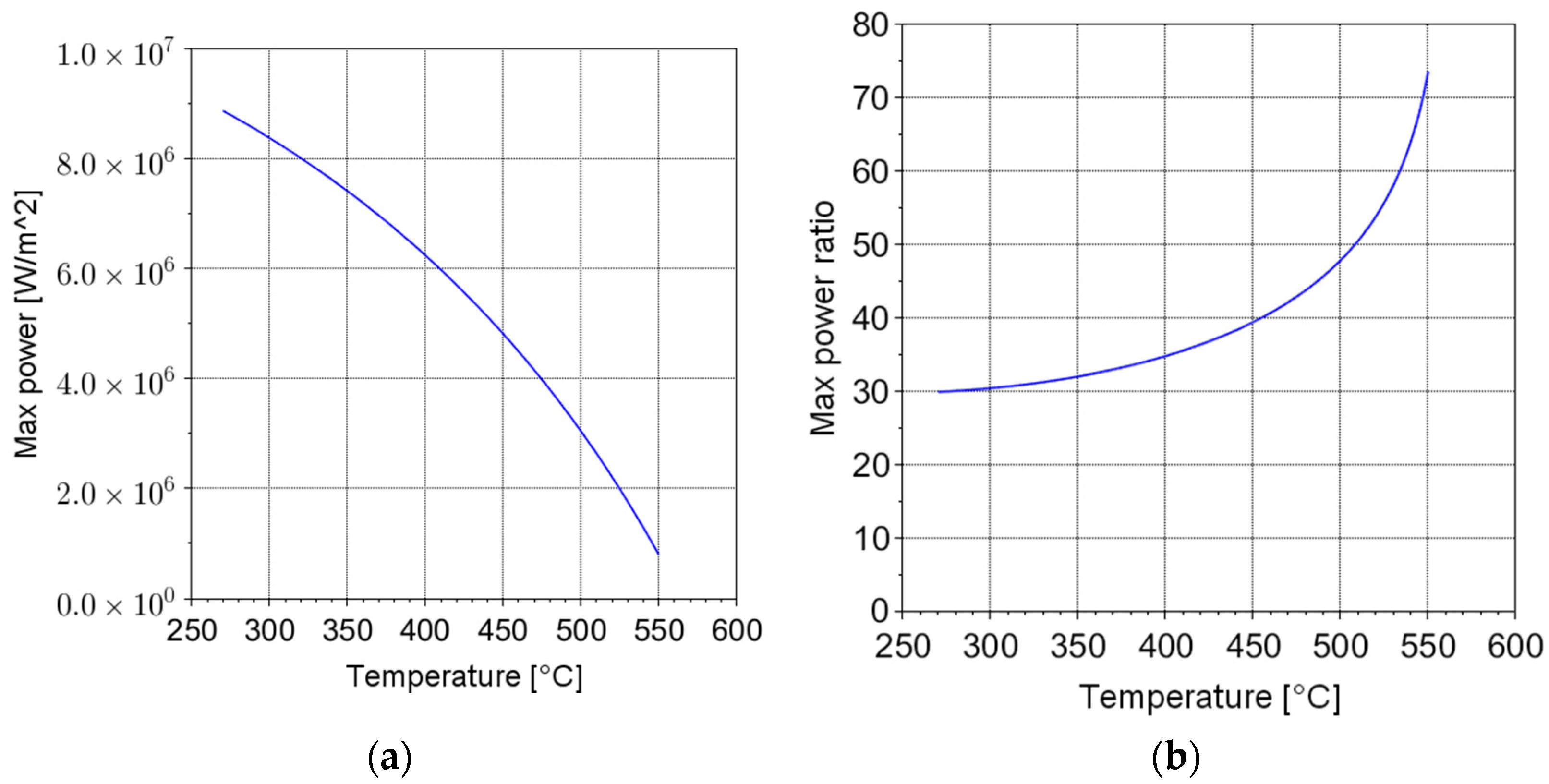
A preliminary analysis was carried out to assess if microwave heating is a promising candidate to overcome the power limitations of Joule heating. Assuming that microwaves come from a window in contact with the salt, and
is the power transferred for the unit area of the window, the maximum power density absorbed by the salt near the window will be
. Let us call
the average residence time of the salt in the heated volume; the maximum transferable power per unit area, considering the constraint of the maximum operating temperature of the salt mixture (565 °C), can be written as
Figure 2 shows
, assuming a residence time equal to 10 s. In addition,
Figure 2 shows the ratio between the maximum power per unit area that can be transferred by microwaves and by the Joule effect. The comparison suggests that an increase in some order of magnitudes of the maximum power can be theoretically achieved by means of the microwave heating technology.
Therefore, both the literature and the theoretical study presented above suggests that microwave heating is a promising technology to heat the considered molten salt mixture. In fact, the volumetric heating mechanism can effectively overcome the power limitation that characterizes the surface heat transfer mechanism of the Joule heating systems.
In the study of [
22], two possible microwave heating configurations are analyzed, adopting two different cavity designs and different wavelengths: in both the systems, the salt flows in a pipe transparent to the microwaves across the cavity. Here, a different approach is proposed, exploring the possibility of heating the salt directly within the storage tank. Such a solution does not require an external circulation of the salt and is well suited for static storages, especially for compact thermocline systems.
5. Integration of the Microwave Heating Technology in a Thermocline Thermal Energy Storage
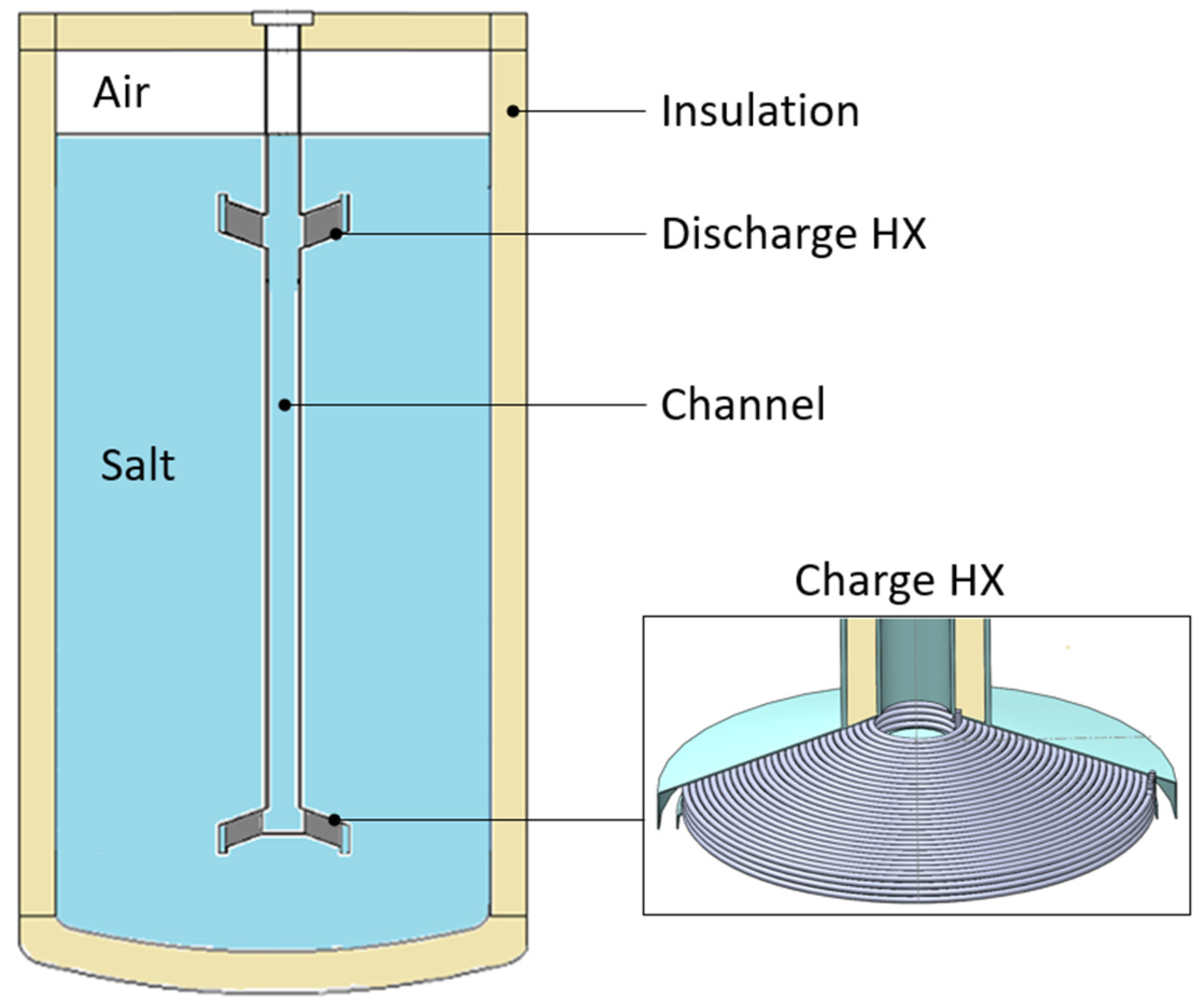
A first possible application of microwave heating technology to a thermal energy storage (TES) has been numerically approached in this work to explore its theoretical feasibility. The reference TES considered in this study consists of a single-medium indirect thermocline storage of 1.3 m in internal diameter and about 2.7 m in height (
Figure 3), which was proposed and experimentally tested in the study of [
23]. It consists of a single tank equipped with two helically coiled heat exchangers (HXs) for the charge and discharge phases, respectively. The discharge HX is located on the top, where the hot storage medium stratifies, while the charge HX is placed on the bottom, where the storage medium is cold. The two HXs are connected by means of a vertical channel that drives the hot/cold fluid during the charge/discharge phases. The tank is at atmospheric pressure. The storage medium in the study of [
23] was a ternary salt mixture, known as Hitec XL, while, in this study, it was replaced with a binary salt mixture (Solar Salt). The heat transfer fluid flowing in the HXs is a mineral oil. A detailed numerical study of such a TES system was presented in the study of [
24].
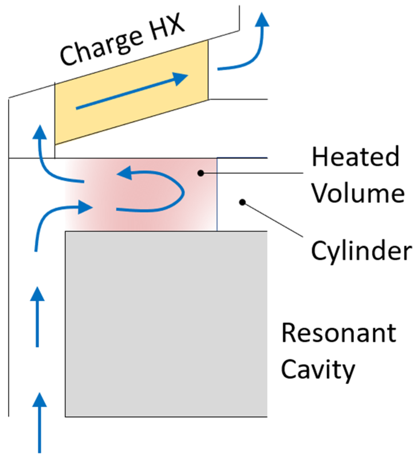
In this work, a resonant cavity was introduced under the charge HX (
Figure 4a) to integrate the microwave heating technology into the reference TES. The resonant cavity can be connected to microwave generators, installed outside the tank, by means of rectangular waveguides. The resonant cavity consists of a cylinder made of stainless steel, except for the top plate, which is made of ceramic material, which is transparent to microwaves. The electromagnetic waves pass through the ceramic plate dissipating their energy in the storage medium. The diameter of the resonant cavity (336 mm) is constrained by the size of the charge HX, while a 200 mm height is assumed. The scope of the resonant cavity is to allow the electromagnetic field to spread in the air volume, resulting in a more uniform distribution, before reaching the salt. The heated region corresponds to the volume between the ceramic plate and the charge HX (
Figure 4b); the height of such a volume is about 40 mm. This height ensures quite a uniform absorption of the electromagnetic waves along the vertical direction since it is lower than the penetration depth (Equation (9)). During the charge phase, the salt mixture flows along the gap between the resonant cavity and the external shield; then, it moves in the region heated by the microwaves to finally pass through the charge HX (see
Figure 4b). In the proposed layout, microwaves preheat the salt before entering in the HX.
A key benefit of the proposed layout is its easy maintenance. In fact, all the immersed devices (HXs, channel, resonant cavity, waveguides) are connected in a single body that can be extracted from the top in case of any failure or regular maintenance.
As abovementioned, the thermocline TES with integrated microwave heating has been numerically tested in this study.
Section 6.1 presents the methodology adopted in the numerical analysis. Particularly, this section describes the thermal-fluid-dynamic (CFD) model developed to simulate the flow field and the temperature distribution established during a charge transient, including the computational domain, the boundary conditions, the computational grid, and the physical models and assumptions considered. Results are discussed in
Section 6.2. The electromagnetic performance of the system was checked in
Section 7 by means of a dedicated model.
6. Thermal Energy Storage: CFD Numerical Model and Results
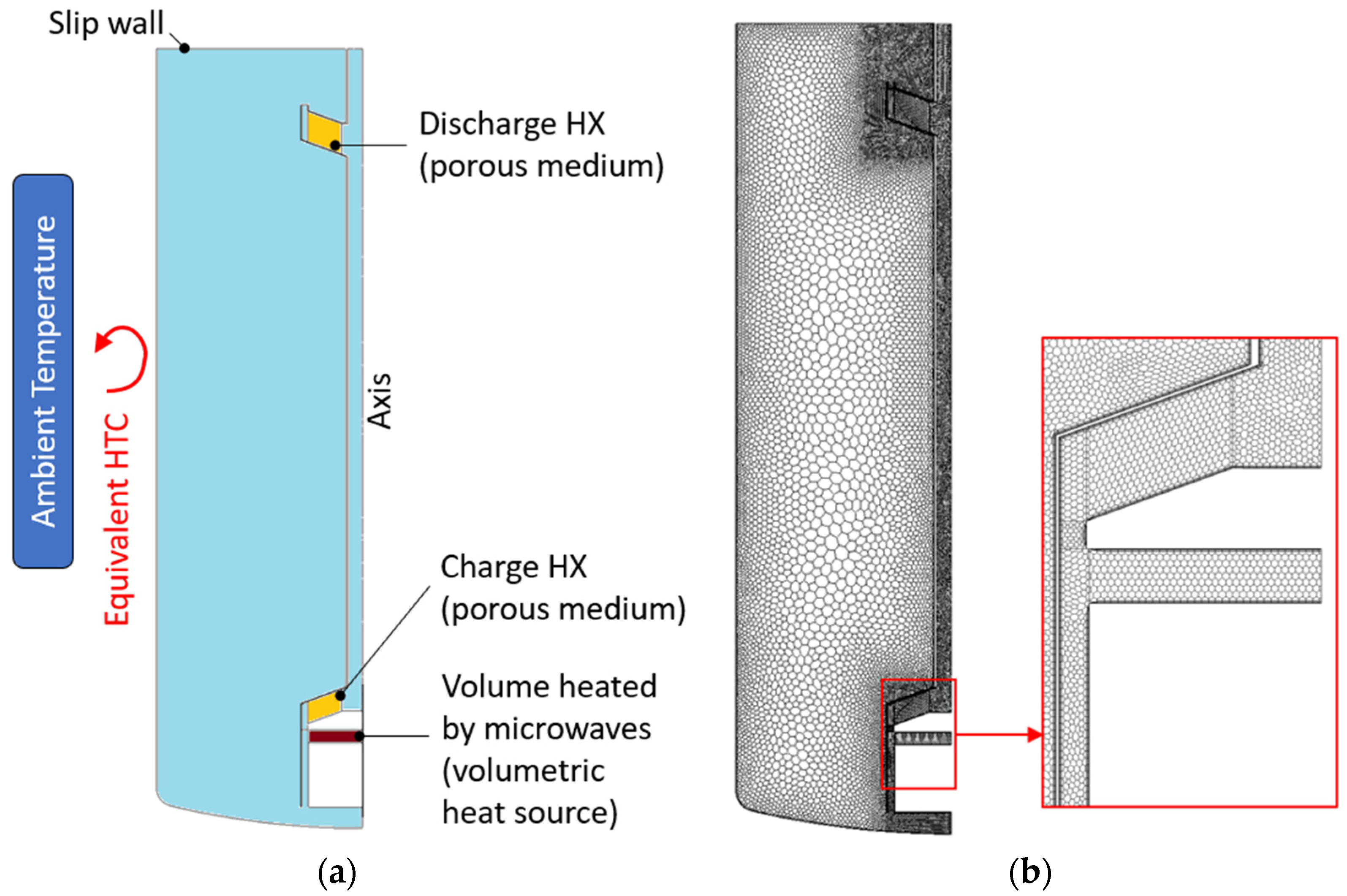
In this study, a light CFD model was developed in Star-CCM+ to perform transient analysis with the aim of numerically studying the behavior of the proposed concept. This model adopts a reduced computational domain, which includes only the molten salt; therefore, walls, insulation layers, and the air layer above the salt-free surface have been excluded. By neglecting the presence of the waveguides, the geometry is symmetric with respect to the tank axis. This implies that the computational domain is 2D axis-symmetric while assuming a uniform volumetric heat source in the region heated by the microwaves. Equivalent heat transfer coefficients (HTCs) were applied at the domain boundaries to consider the heat losses towards the external ambient (see
Section 6.1). The charge and discharge HXs were replaced with an equivalent porous medium by applying the procedure described, for example, in the study of [
25]. The medium porosity is about 0.656, the computed permeability is 1.032 × 10
−6/1.135 × 10
−6 m
2, and the inertial coefficient is 0.253/0.319 for the charge/discharge HX. The computational domain and the boundary conditions applied are summarized in
Figure 5a.
The CFD model solves the dynamic mass, momentum, and energy equations by applying a laminar model and including the buoyancy forces by means of the Boussinesq approximation. The salt-free surface is treated as a slip wall. The computational grid adopted consists of 2.4 × 10
5 cells with three boundary layers at the wall/fluid interfaces (
Figure 5b). The mesh independence of the solution was checked.
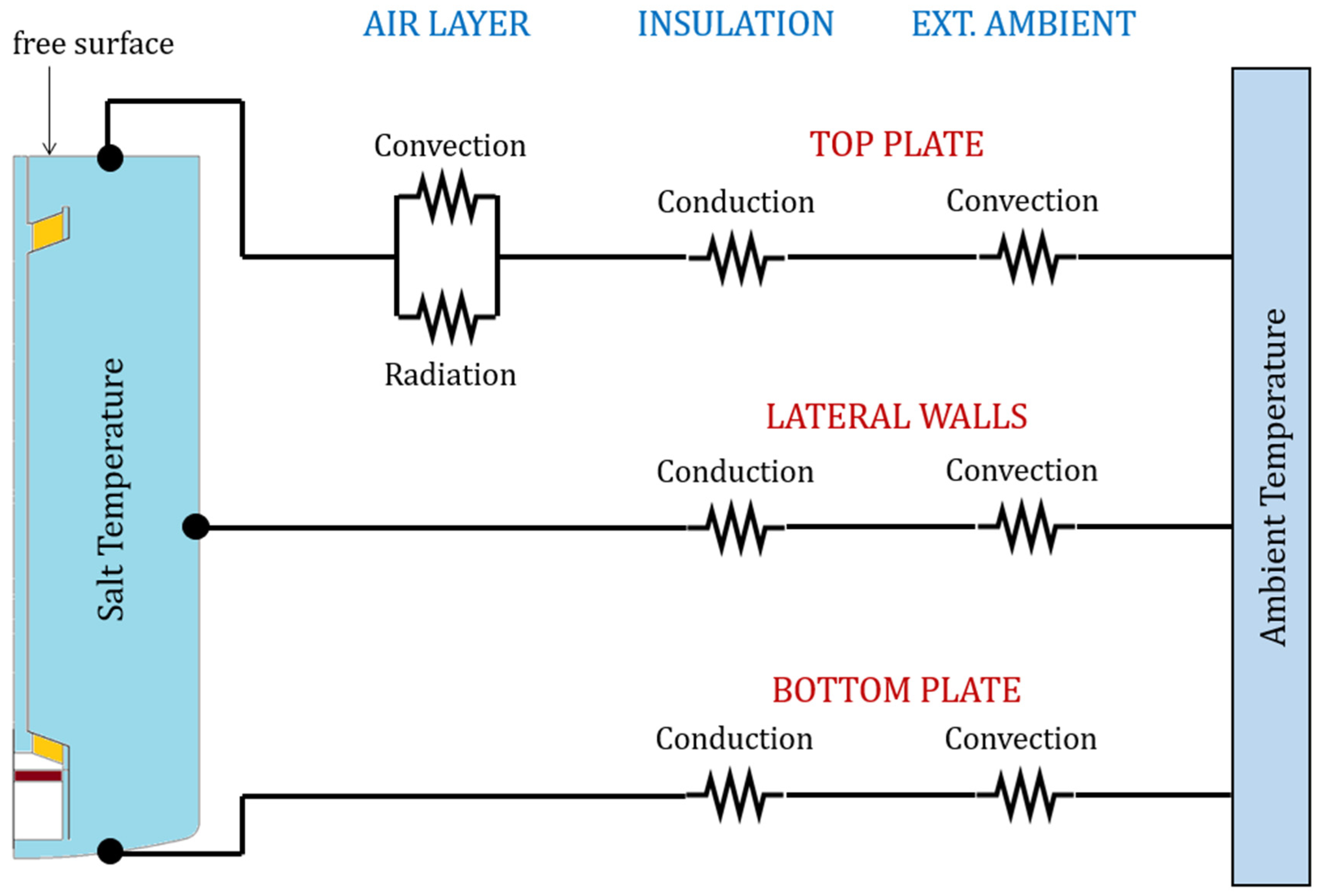
6.1. Heat Loss Evaluation
To evaluate the heat losses from the salt boundary surfaces towards the external environment, the equivalent thermal resistance scheme in
Figure 6 was considered. The assumptions introduced here are listed below:
The resistance offered by the tank wall was ignored because of the high thermal conductivity of the stainless steel and of the small wall thickness;
The radiative share of the heat transfer from the insulation outer surface to the environment was neglected. In fact, the heat transfer is likely dominated by convection due to the expected surface temperatures that should approach the ambient temperature;
The lateral wall of the tank is assumed to be entirely in contact with the salt, neglecting the small portion (about 200 mm) at the very top that is in contact with the air;
The lower cap of the tank is approximated as a flat plate;
The top cap of the tank is approximated as a flat plate, neglecting the thermal bridges induced by the flanges;
Salt temperature is assumed to have a uniform distribution.
A detailed insight into the heat transfer phenomena in
Figure 6 is reported in the sections below. Solving this thermal resistance scheme allows for determining an equivalent heat transfer coefficient for each surface considered. This calculation was carried out for a given ambient temperature (25 °C) and varying the salt temperature (290, 420, 550 °C) and the wind speed (0, 2, 4, 8 m/s). Results are shown in
Figure 7a and
Figure 7b for the natural and forced convection case, respectively. Overall, the equivalent HTC falls within a narrow interval of values. This is because the insulation layer effectively decouples the storage medium from the environment. Given the results in
Figure 7, it is reasonable to assume an average equivalent HTC, equal to 0.86 W/m
2K, for all the boundaries and for both natural and forced convection.
6.1.1. Heat Transfer Through the Insulation
The insulation layer consists of 300 mm of Rockwool, whose thermal conductivity is 0.35 W/mK. The conduction resistance offered by the insulation layer is computed according to Equations (14) and (15) for the top/bottom plate and lateral walls, respectively.
where Δ
x is the plate thickness,
k is the insulation thermal conductivity,
A is the heat transfer area, and
D and
L are the diameter and the length of the cylinder, respectively. Subscripts
int and
ext refer to the internal and external surfaces of the hollow cylinder.
6.1.2. Heat Transfer from the Insulation Outer Surface to the Environment
The heat transfer towards the environment occurs by convection. The corresponding thermal resistance is defined as follows:
where
h is the convective heat transfer coefficient,
A is the heat transfer surface,
Nu is the Nusselt number,
k is the fluid thermal conductivity, and
Lc is the characteristic length. Suitable correlations were implemented to estimate the Nusselt number. If the flow is gravity-driven (natural convection), Equations (17)–(19) are adopted for the case of vertical plate (lateral wall), the upper surface of hot horizontal plate (top plate), and the lower surface of hot horizontal plate (bottom plate), respectively [
26].
In these correlations, Ra is the Rayleigh number, and Pr is the Prandtl number. The characteristic length is the height of the vertical plate and the ratio between the area and the perimeter for the horizontal plates. All the properties are evaluated at mean temperature.
In the case of wind (forced convection), the Churchill and Bernstein correlation for cylinders in cross-flow (Equation (20)) was adopted for the lateral wall, while a correlation for parallel flow over an isothermal plate (Equation (21)) was considered for both the top and the bottom plate [
26].
where
Re is the Reynolds number evaluated considering the tank outer diameter as a characteristic length. Also, in this case, all the properties are evaluated at mean temperature.
6.1.3. Heat Transfer Through the Air Layer
The heat transfer between the salt-free surface and the tank roof occurs by convection and radiation. An approximation of the convection coefficients for the rectangular horizontal cavity heated from below is obtained from the correlation proposed by Globe and Dropkin (Equation (22)) [
26], where all the properties are evaluated at the mean temperature.
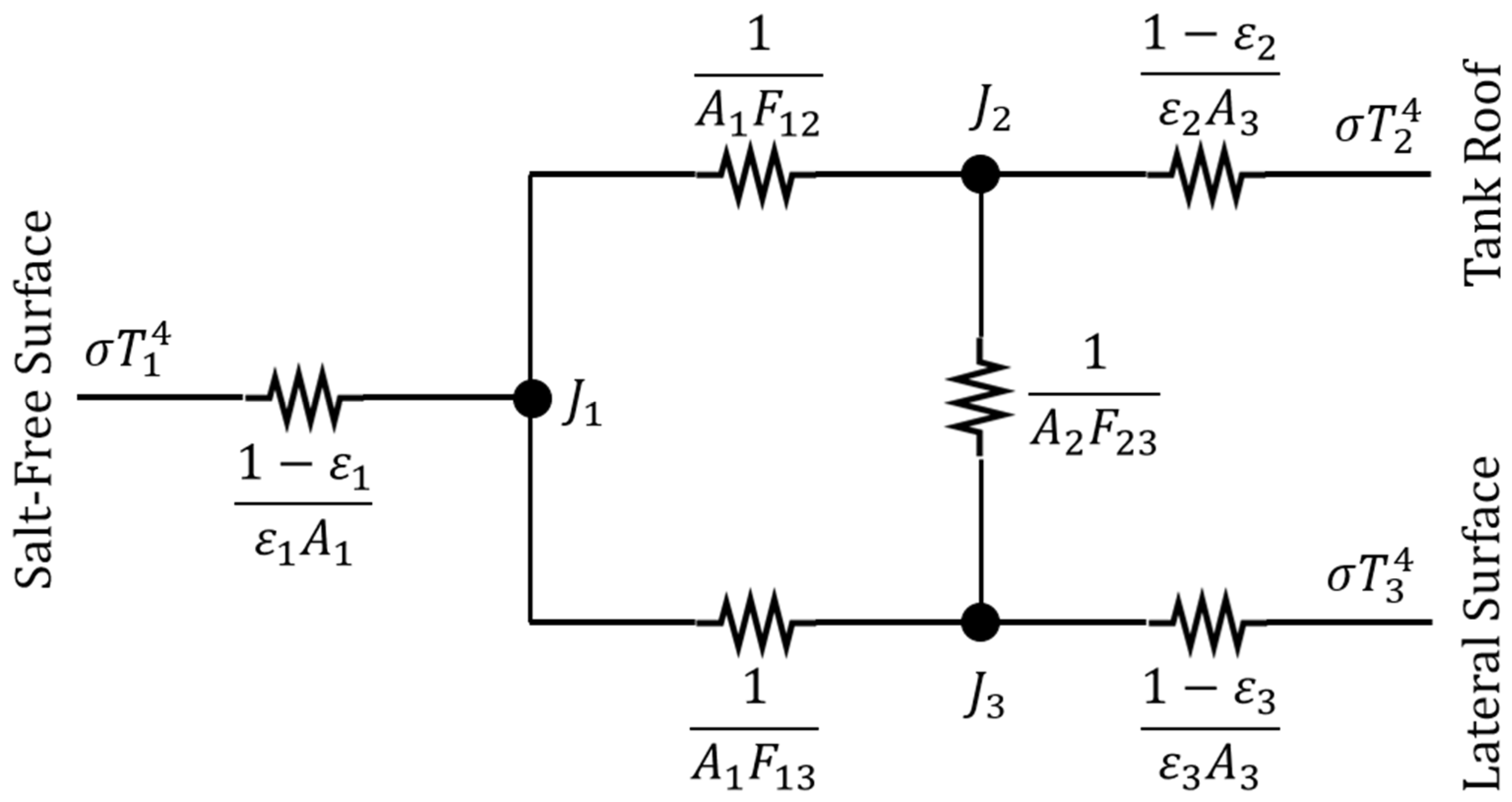
Regarding the radiative share of the heat transfer, the radiation network approach was adopted here. The problem consists of an enclosure with three opaque, diffuse, gray surfaces: namely, the salt-free surface, the tank roof, and the lateral side of the air layer (
Figure 8).
In the scheme of
Figure 8,
T is the surface temperature, σ is the Stefan–Boltzmann constant,
J is the radiosity,
A is the surface area, and
Fij is the view factor between the surface
i and
j. The emissivity ε is about 0.9 for molten salts [
27], while an emissivity of 0.6 was considered for stainless steel. The temperature of the tank roof is approximately equal to that of the lateral surface (
T2 = T3), which is the temperature of the wall at the interface with the air layer. The area of the salt-free surface is the same as the tank roof (
A1 = A2). The view factor between the salt-free surface and the tank roof can be computed according to Equation (23) [
26], which is valid for coaxial parallel disks with an equal radius (
r) at a given distance (
d). The view factor
F13 is the complement to 1 of
F12, and
F23 is equal to
F13.
Solving the radiation network in
Figure 8 allows for determining the values of the radiosity at nodes. The quantity of interest for the purpose of this section is the heat flux exchanged between the salt-free surface and the tank roof, which is given by the following equation:
6.2. Results and Discussion
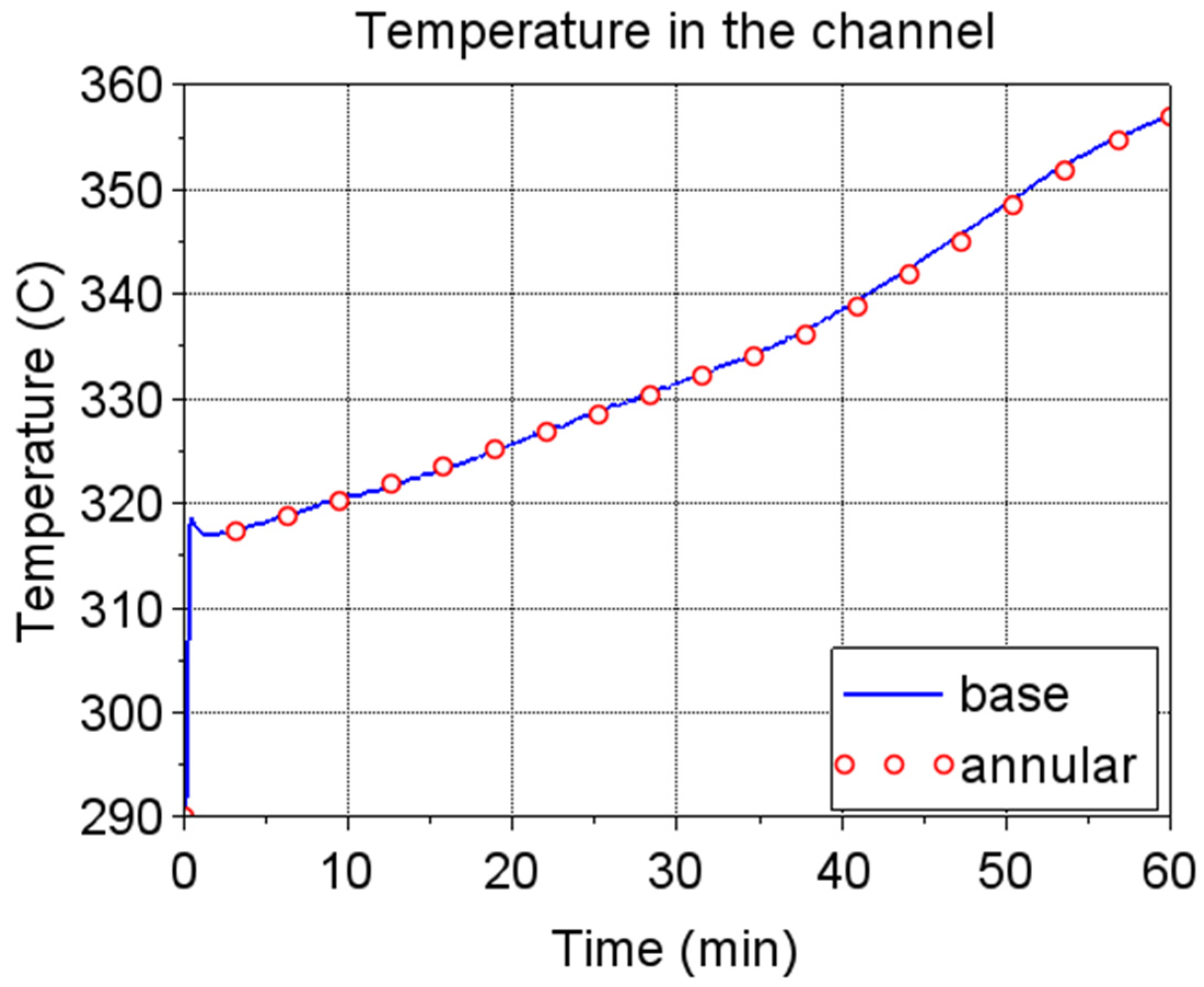
A 60 min charge transient was simulated considering an ambient temperature equal to 25 °C, an initial uniform salt temperature of 290 °C, and the salt bulk at rest at the initial time. The thermal driver consists of a uniform volumetric heat source (110 kW) applied to the volume heated by microwaves.
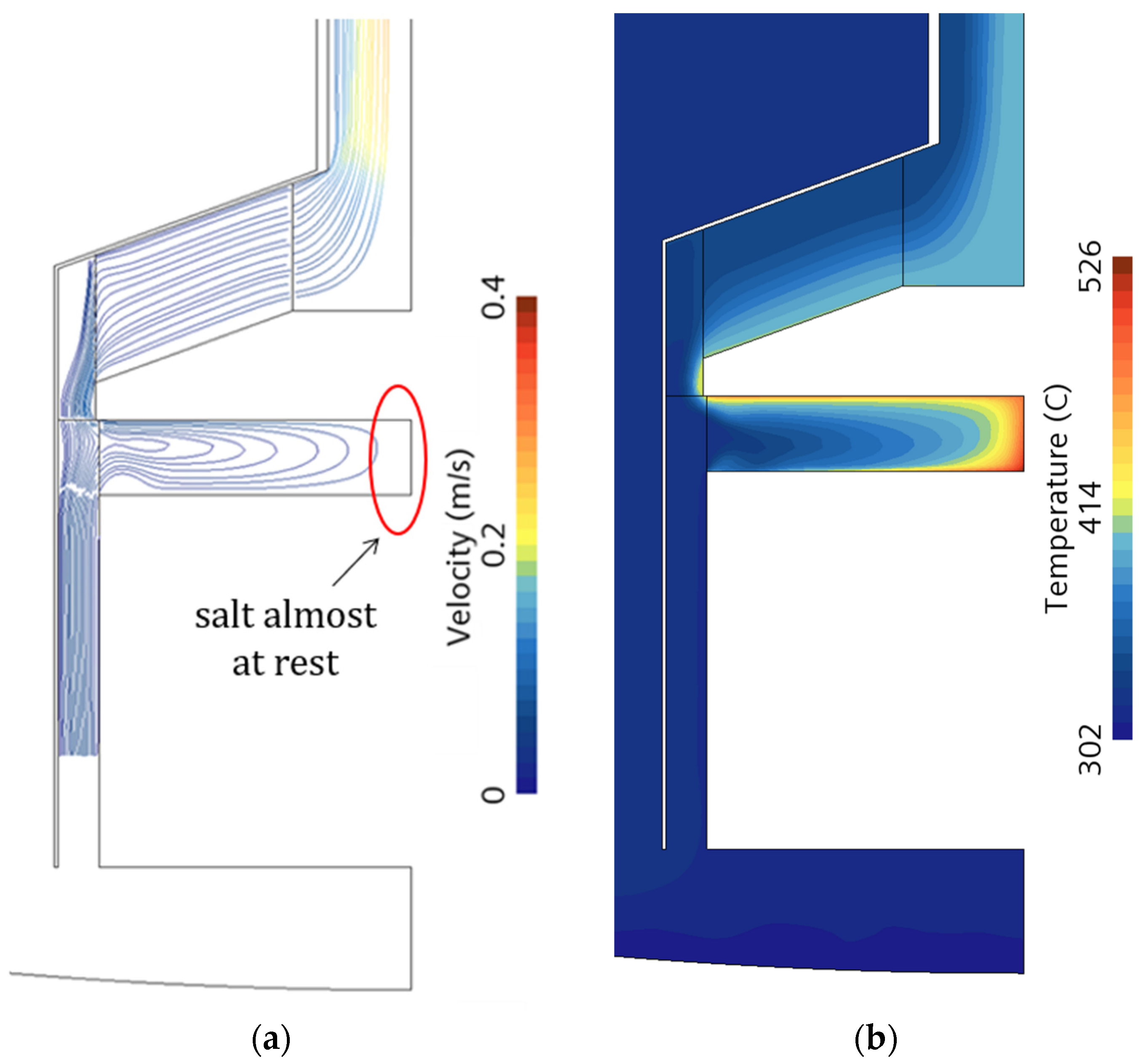
Figure 9 shows the computed velocity field and the salt temperature distribution at the end of the transient in the region around the heated volume. Looking at this region, the salt circulation established at the tank axis location is almost negligible, leading to local high temperatures.
To prevent high temperature peaks, a design modification may be considered. Particularly, the region of no salt circulation was removed by introducing a cylinder of 4 inches in diameter at the axis location (see
Figure 10). Therefore, the heated volume corresponds to the annular region surrounding the cylinder. The corresponding velocity and temperature fields (
Figure 11) confirm that the flow motion now involves all the heated volumes, resulting in a lowering of the temperature peak. However, the temperature distribution in the heated region is non-uniform. Close to the bounding surfaces, the fluid velocity is almost zero because of the boundary layer (no-slip condition), which explains the high temperatures observed at the fluid/solid interface. This phenomenon partially limits the benefit of the volumetric heating mechanism.
Figure 12 and
Figure 13 compare the original and the modified (annular) design in terms of time evolution of the maximum salt temperature reached in the heated volume and time evolution of the salt temperature in the vertical channel, respectively. The latter represents the useful effect of microwave preheating. The annular configuration allows for reducing the maximum temperature of about 50 °C while keeping the same average temperature in the channel. In
Figure 12, the temperature starts rising between 30 and 40 min because the inlet temperature, i.e., the temperature at the tank bottom, increases.
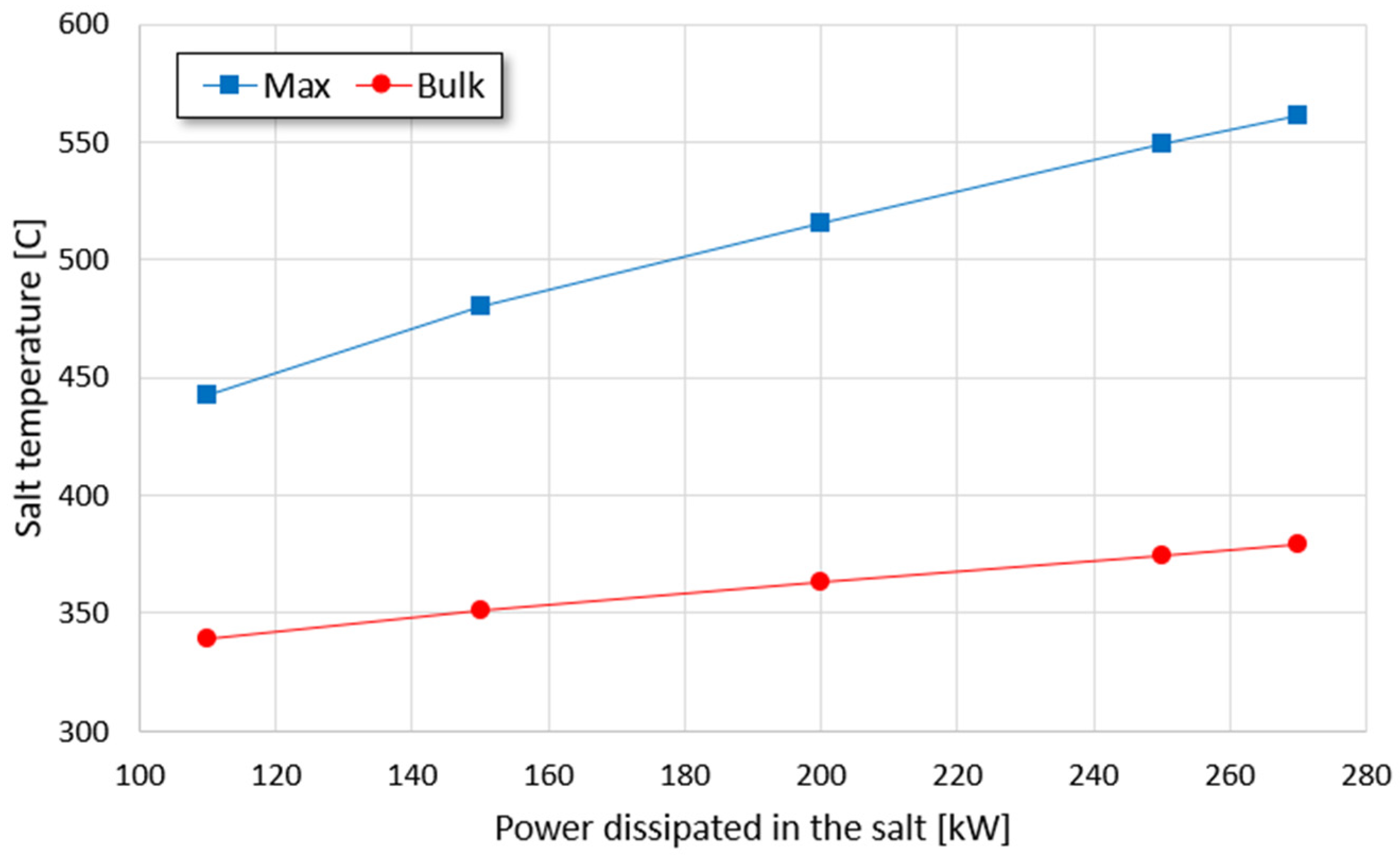
A set of 25 min transient simulations were carried out varying the volumetric heat source (
Figure 14), considering the constraint given by the maximum operating salt temperature (565 °C). The reduced transient time (25 min) is to discard the part of the transient affected by the increased temperature at the bottom of the tank. The aim of this analysis is to assess the potential of the proposed thermocline TES with integrated microwave heating in terms of dischargeable power.
According to
Figure 14, the maximum power that can be discharged without degrading the salt is about 270 kW; the corresponding bulk temperature is about 380 °C. Considering
Section 5 (
Figure 1), almost 45 m of a 1 cm diameter resistance rod is required to dissipate the same power at the same bulk temperature. This resistance-based solution is still feasible; however, the obtained length of the rod is optimistic since it comes from a theoretical calculation that does not consider, for instance, the actual displacement of the resistances in the tank. In addition, the proposed microwave heating system has plenty of room for improvements, for example, by enhancing the fluid mixing at the bounding surfaces of the heated region to lower the maximum temperatures. Therefore, the proposed (roughly optimized) microwave heating device performs in a comparable way with respect to a (ideal) Joule heating element. This suggests that the microwave heating technology has a great potential while combined with thermocline TES.
7. Electromagnetic Performance
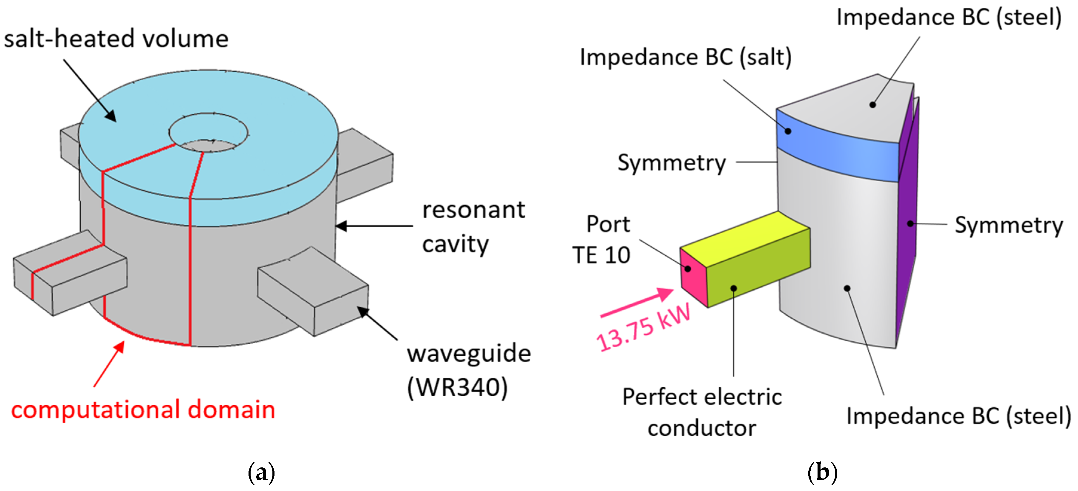
Once the thermal-fluid-dynamic behavior of the proposed thermocline concept was verified, the electromagnetic performance was evaluated considering the final design coming from the CFD analysis. For this purpose, a dedicated 3D model was developed using COMSOL 6.1. The computational domain corresponds to the resonant cavity, a representative portion of the waveguide (about a wavelength) and the heated salt volume. The waveguide belongs to the WR340 family (3.4 × 1.7 inches), which is suitable for frequencies in the range 2.20–3.30 GHz. It is supposed that four waveguides, equally spaced along the azimuthal direction, are connected to the resonant cavity. Therefore, the minimum computational domain is one-eighth of the entire domain (see
Figure 15a). The boundary conditions applied are summarized in
Figure 15b. Particularly, a rectangular TE 10 port was applied at the end of the waveguide portion. The imposed power at the port corresponds to that applied in the thermal-fluid-dynamic study (110 kW globally). The waveguide walls are supposed to be copper-coated; thus, the perfect electric conductor approximation is suitable here. The stainless-steel walls were replaced with an impedance boundary condition; the same approach was applied to the salt/salt interface at the side of the heated volume. The computational grid consists of about 4.4 × 10
4 tetrahedral cells, which is enough to ensure mesh-independent results.
The salt dielectric properties were varied, according to Equations (11) and (12), considering three salt temperatures in the working range (290, 420, and 550 °C).
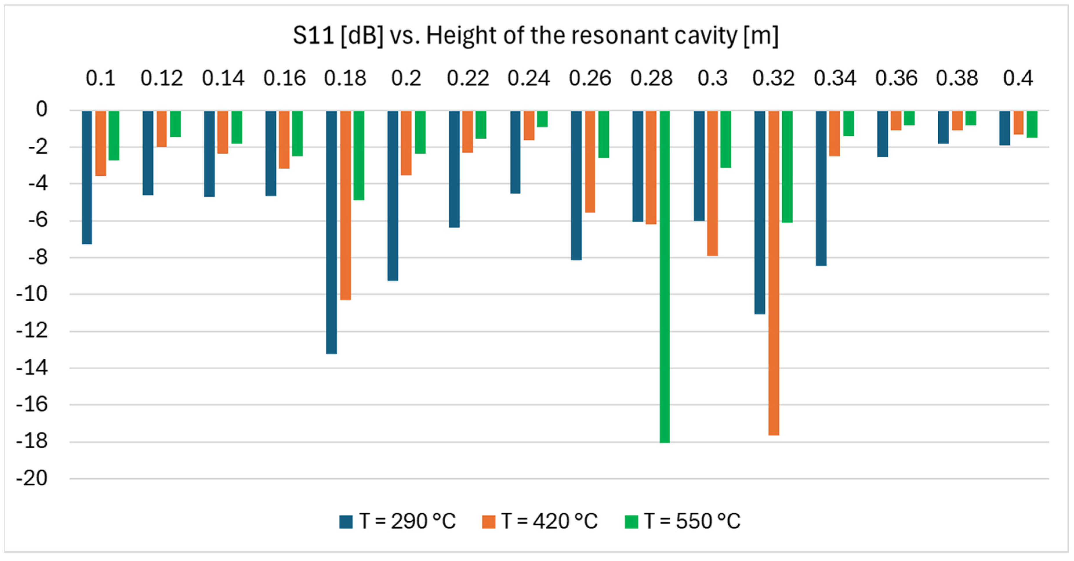
The diameter of the resonant cavity is constrained by the charge HX size, while its height can be varied parametrically around the default value of 200 mm assumed in this thermal-fluid-dynamic study. The microwave frequency was imposed to be equal to 2.45 GHz. The key performance indicator adopted in this study corresponds to the scattering parameter (S11), which provides a measure of the electromagnetic power reflected back towards the waveguide.
Figure 16 shows the results of this parametric analysis. Electromagnetic performance changes considerably in the parametric space explored, moving from −2.7 dB (about 54% power reflected back) to −18.1 dB (less than 2% power reflected back). Varying the salt temperature, i.e., the dielectric properties, the best performing height changes.
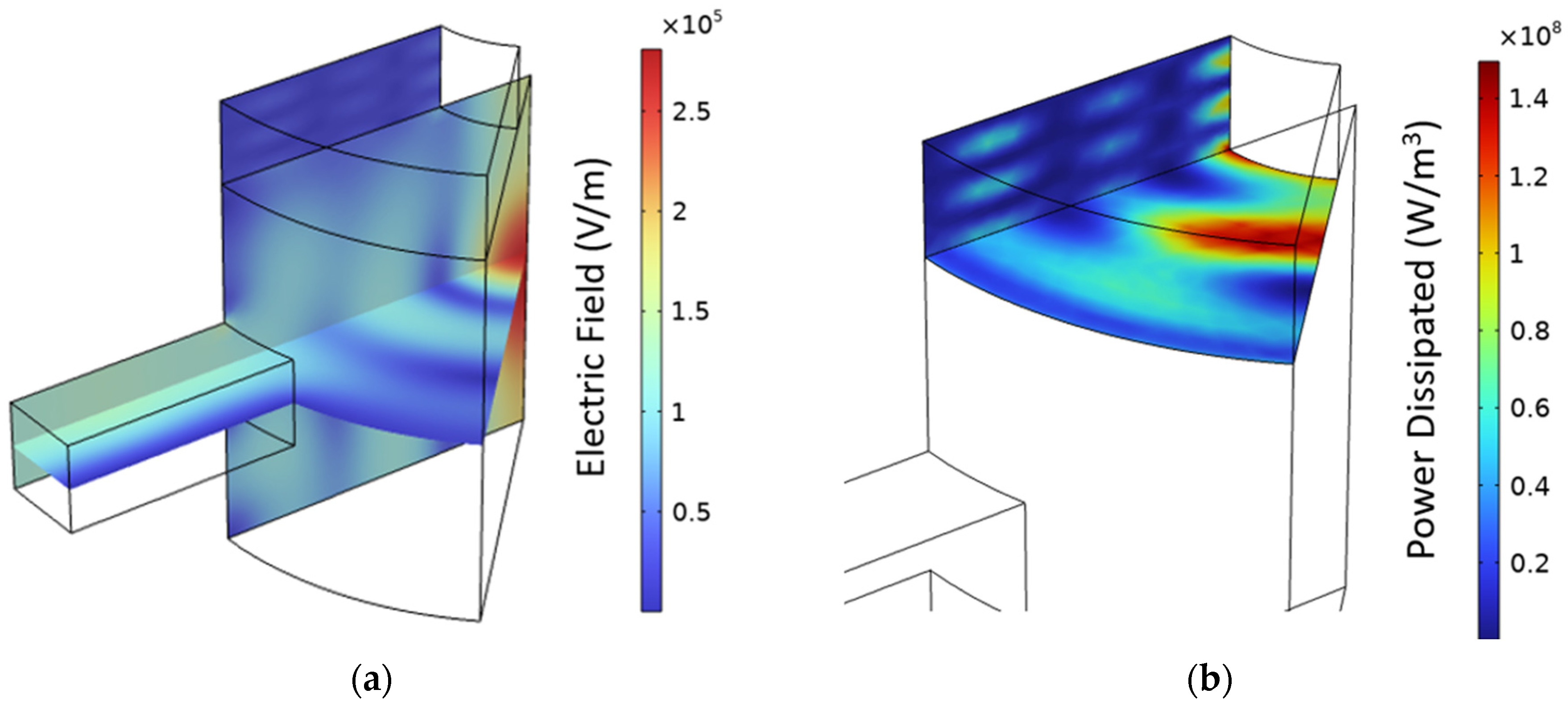
The actual height of the resonant cavity may be referred, as a first approximation, to the average salt temperature in the heated volume, in this case, about 347 °C. Repeating the parametric study while considering the salt dielectric properties at such a temperature, an optimal height of 180 mm was identified (S11 = −27.7). Considering this design,
Figure 17 shows the computed electric field in the domain and the corresponding power dissipated in the salt. The latter is clearly non-uniform, especially along the radial and azimuthal direction. An evaluation of the impact of the non-uniform distribution of the heat source in the thermal-fluid-dynamic model is out of the scope of this work but represents an interesting perspective for the future.
8. Conclusions and Perspective
Storage systems are crucial for the global transition to renewable energy, given the projected significant contribution in the future from VRE sources. Besides the capacity, the maximum charging power of a storage system is a key factor. Sensible heat thermal storages using molten salts as a storage medium can play a significant role due to their low cost, material availability, absence of critical materials, simplicity, potentially large storage capacity, and inherent ability to interface with both thermal and electrical grids. Indeed, these systems can be charged using both heat and electricity, with grid electricity peaks easily converted to thermal energy for storage purposes. However, power limitations associated with conventional Joule effect electric heating can significantly hinder their diffusion. This paper presents a theoretical analysis investigating possible electricity into heat conversion approaches, with a focus on maximizing power release in Solar Salt-based storage systems. It evidences that a full charge—up to the maximum operating temperature—via Joule effect only is likely not feasible. Therefore, the volumetric heating of molten salt mixtures using microwaves is proposed as an alternative to conventional Joule heating systems, in order to overcome the power limitations. Despite the few experimental data available on the dielectric properties of molten salts at microwave frequencies, the available data show that this technical solution can be promising. A first theoretical analysis indicates a potential increase of more than 10 times in the maximum power transferable per unit area. To explore the feasibility of microwaves heating in molten salt thermal storage systems, a numerical study was here conducted on a single-tank thermocline TES with an integrated microwave heating device. For this purpose, a CFD model was developed, which allows for the evaluation of the flow field and the temperature distribution in the salt domain. A first geometrical optimization of this concept was presented and discussed, proposing a specific configuration to mitigate high-temperature peaks in regions with limited salt circulation. Results indicate that the proposed microwave heating device can be competitive with respect to resistance-based heating, reaching a maximum dischargeable power of 270 kW at a bulk temperature of about 380 °C. However, further design optimizations are required to lower the peak temperatures at the bounding surfaces of the heated volume, which partially nullify the advantage of the volumetric heating mechanism of practical use in such storage systems. The microwave heating device was then analyzed from an electromagnetic point of view by means of a dedicated model. The latter computes the electromagnetic field in the salt-heated region, determining the power absorbed by the salt, as well as the power reflected back toward the waveguide. Results show that the effectiveness of the heating system is highly dependent both on the dielectric properties of the salt and on the shape and size of the microwave cavity. Both these aspects deserve further experimental investigations and will be the focus of future development efforts.
Several perspectives can be identified for this work. First, a design optimization of the microwave heating device should be carried out, also developing a fully coupled thermal-fluid-dynamic and electromagnetic numerical model. Second, the salt dielectric properties should be experimentally verified. Third, a numerical study should be performed to assess the large-scale performance of the technology.


