Article

Numerical Simulation of CO2 Injection and Extraction Heat Transfer in Complex Fracture Networks

by
Yuguo Liu
1,
Xiaolong Zhao
1,*,
Yizhong Zhao
2,
Peng Zhao
3,
Yinghui Zhu
1,
Yi Wu
3 and
Xinru He
3
1
Research Institute of Petroleum Engineering, Sinopec Shengli Oilfield Company, Dongying 257000, China
2
Zhongsheng Petroleum Development Co., Ltd., Sinopec Shengli Oilfield Company, Dongying 257000, China
3
College of Energy, Chengdu University of Technology, Chengdu 610059, China
*
Author to whom correspondence should be addressed.
Energies 2025, 18(7), 1606; https://doi.org/10.3390/en18071606
Submission received: 25 February 2025 / Revised: 4 March 2025 / Accepted: 18 March 2025 / Published: 24 March 2025
(This article belongs to the Special Issue Development and Utilization in Geothermal Energy)

Abstract

:
In order to reveal the heat transfer mechanism of CO2 injection and extraction in the fracture network of geothermal reservoir rock, based on the assumption of a dual-media model and considering the characteristics of the rock matrix and the fracture network, the changes in the physical properties of the heat transfer fluid, and the effects of multi-field coupling, a coupled thermo–hydro–mechanical (THM) model of CO2 injection and extraction heat transfer was established. A numerical simulation study was carried out to investigate the evolution of injection and extraction temperature and heat extraction performance under the influence of different factors in the randomly distributed fracture network of the reservoir rock, which has a horizontal slit and a high-angle slit, with CO2 as the heat transfer fluid. The results show that the heat exchange efficiency of reservoir fracture is higher than that of rock matrix; compared with water, the CO2 heat extraction rate is low, and the temperature drop in production wells is small, which is favorable to the long-term exploitation of geothermal reservoirs. if the horizontal distance between the production wells and the injection wells is far and the fracture connectivity is good, the heat exchange is strong and the heat extraction rate is higher; increasing the CO2 injection rate will increase the range of the low-temperature area, reduce the temperature of the production wells, and increase the heat extraction rate in a short period of time; and the heat extraction rate will increase in the later stages. The increase in CO2 injection rate will rapidly increase the range of the low-temperature area in a short time, decrease the temperature of the production well and increase the heat extraction rate, and then the growth of the heat extraction rate tends to stabilize in the later stages; the width ratio of horizontal fracture and high-angle fracture affects the direction of heat exchange, the temperature of production well and the heat extraction rate, and the influence is more significant when the width ratio is greater than 1; the temperature of the production well decreases fastest, the increase in the heat extraction rate is largest, and the effects on the temperature of the production well and the heat extraction rate are insignificant when it is close to the production well. The increase in the heat extraction rate is slower when close to the injection well.

1. Introduction

At a time when the global energy structure is accelerating towards low-carbon transition, geothermal energy, as a green, clean and sustainable energy source, has received widespread attention [1]. However, at the present stage, the development and utilization of geothermal resources are generally faced with the problems of the unclear mechanism influencing heat exchange during injection and extraction, the short life of thermal reservoirs and low heat exchange efficiency, which limit its large-scale popularization and application. In order to explore the exploitation mechanism for geothermal storage and improve the efficiency of geothermal exploitation, more scholars have conducted a large number of experimental and numerical simulation studies on the influencing factors in the process of heat exchange in injection and mining, taking dry heat rocks, sandstone and other thermal storage rock bodies as the research objects.
From an experimental perspective, Zhao Peng et al. [2] carried out long-term one-injection-one-mining and one-injection-two-mining large physical modeling tests using Qinghai Republican dry heat rock, and systematically analyzed factors such as mining flow rates, temperature, and heat extraction rates of production wells. The results showed that the combined effect of thermal shock and injection pressure will enhance the conductivity of the cracks and communicate or activate the local closure areas of the cracks, thus affecting the long-term and efficient development of dry heat rock. Huizheng et al. [3] studied the variation rule of the heat transfer coefficient of single fissures in smooth sandstone in high- and low-temperature zones under different operating conditions, and the results showed that the injection rate of fluid and the initial temperature of the rock samples have stronger effects on the heat transfer coefficient than the opening of the fissure. He [4] and Luo [5] carried out a pilot study on the heat transfer characteristics of the water flowing through a single rough fissure, pointing out that the fissure roughness plays a key role in the heat transfer process. In a numerical simulation, Yao et al. [6] analyzed the distribution of stress, temperature and deformation in a reservoir based on the discrete fissure model, and concluded that changes in reservoir pressure and temperature will cause the reservoir fissure to move, which will change the transmission characteristics of the reservoir. Song et al. [7] established the temperature–permeability–stress field coupling of three-dimensional fissures. Du et al. [8] simulated the heat extraction process of a geothermal reservoir using the finite volume method, and analyzed the reservoir fissure pressure, temperature and fissure openness in detail, pointing out that an increase in the injection rate will shorten the life of the enhanced geothermal system, and a reduction in the fissure permeability can avoid the formation of a thermal short-circuit effect, which is conducive to the improvement of production performance. Wang Tianyu et al. [9], based on the multi-branch radial well geothermal development model of heat–fluid–solid coupling, investigated factors such as well fabrication parameters and natural fissure seam length in the heat extraction process, indicating that shrinkage and deformation of the rock in the process of heat extraction will increase the permeability of the fissure, exacerbate the time of thermal breakthrough, and shorten the life of the system in the extraction of heat. Sun et al. [10] established a THM coupling model of discrete fractures and studied the heat extraction effect of the heat flow model as well as the heat-flow-solid model, pointing out that the heat-flow-solid three-field coupling effect has an important influence on the heat extraction effect.
In the process of researching the injection and extraction heat transfer process in rock fissures, most scholars regard the research object as a smooth or rough single fissure [3,4,5,8,10], and there are fewer studies on the complex fissure network. At the same time, some scholars neglect the influence of temperature change on the permeability of reservoir rocks or fissures [11,12], so the obtained phase-concerned extraction heat transfer law cannot depict the injection and extraction heat transfer process in the real reservoir fissure. In addition, due to the large depth of geothermal reservoirs, the rock bodies in reservoirs are generally very dense, with low porosity and permeability [13,14], and the efficiency of geothermal mining using conventional methods is low. Enhanced geothermal systems inject low-temperature and high-pressure fluids into reservoirs by using fracturing technology to hold the pressure and build a complex fracture network, which improves the permeability of the reservoir and provides an effective way of efficiently mining low-permeability geothermal reservoirs [15,16,17,18]. A conventional EGS uses water as the injection fluid for heat exchange, but water will chemically dissolve, precipitate or scale with the reservoir rock in the process of heat exchange, which will change the permeability of the reservoir [19,20,21,22]. At the same time, high-pressure water will also disturb in situ stress in reservoirs, which can easily activate faults and induce earthquakes. On the other hand, water as a heat transfer fluid has high consumption and a low recovery rate, and there are great regional limitations in water-scarce thermal storage areas [23]. In recent years, due to its unique physicochemical properties, CO2 has gradually become a promising alternative for injection fluids in geothermal energy extraction, and the emergence of CO2 injection and extraction heat transfer technology provides a new way of thinking about the efficient development of geothermal resources. This technology, by injecting CO2 into geothermal reservoirs under high-temperature and high-pressure conditions, will transform CO2 into a supercritical state with low viscosity [24], high diffusivity and good heat transfer performance. The CO2 can then flow more efficiently in the fracture network and exchange heat with the rock to increase the temperature and yield of the geothermal fluid and realize the sustainable development of geothermal resources.
There have been a large number of studies on the flow and heat transfer characteristics of water in the fracture networks of geothermal reservoir rocks [10,25,26]; however, there is still a lack of refined numerical simulation studies on the heat transfer process of CO2 injection and extraction in natural fractures. Shi Yu et al. [27] comparatively analyzed the heat extraction effects of water and CO2 in a multi-branch geothermal system, pointing out that CO2 in the reservoir has a better heat extraction effect, but the study neglected the influence of fracture morphology on the whole heat extraction system. Ren Shaoran [28], Chen [29], Wang [30] and others used numerical simulation methods to compare and analyze the heat extraction effects of supercritical CO2 and water and pointed out that the supercritical CO2 heat extraction rate is higher than that of water and it is more obvious in reservoirs with lower permeability and temperature. Most of the existing studies focus on simple models under ideal conditions and fail to fully consider the influence of the complex geometry of natural fractures and practical factors such as multi-field coupling effects on injection and extraction heat transfer efficiency.
In view of this, it is of great significance to conduct an in-depth study on the injection, production and heat exchange mechanisms of CO2 in the complex fracture networks of geothermal rock masses, so as to achieve a combination of carbon sequestration and clean energy extraction [31,32]. This study used the distribution characteristics of natural granite outcrops and reservoir fractures in the Qinghai Gonghe Basin and generated a 2D fracture network containing horizontal fractures and high-angle fractures using numerical simulation methods. A thermo-hydro-mechanical (THM) model suitable for heat transfer during CO2 injection and production was established. Through numerical simulation, the heat transfer patterns of CO2 injection and production in horizontal and high-angle fracture networks were investigated under the influence of factors such as the location of production wells, CO2 injection rates, initial fracture widths, and the number of high-angle fractures. In so doing, we provide a theoretical basis and technical reference for the efficient development of geothermal energy in geothermal reservoirs and the geological utilization of CO2.

2. THM Theoretical Modeling

2.1. Basic Assumptions

Before conducting the numerical THM simulation in this study, in order to satisfy the reasonableness and correctness of the calculation, the basic assumptions of the established model were adopted: (1) The reservoir rock body is regarded as a dual medium model, including the rock matrix and the fracture network, among which, the rock matrix is regarded as a single elastic material with porous characteristics and the influence of temperature change on its permeability is considered in the process of the study. (2) The flow of the heat transfer fluid in the fractures satisfies Darcy’s law, which is used to characterize the flow of a fluid in a porous medium, and the changes in the physical properties of the heat transfer fluid with temperature and time are considered. (3) The conduction and distribution of temperature in the reservoir follow Fourier’s law, and the theory of local thermal equilibrium is satisfied between the rock and the fluid in a tiny localized region.

2.2. THM Governing Equations

The mass balance equations for the heat transfer fluid in the rock matrix and the fracture network, respectively, as well as the Darcy velocity, are shown in the following equations [33]:
For the rock matrix
S p t + q = α ε v t Q f
q = k μ ( p + ρ w g z )
For fracture networks
d f S f p t + τ ( d f q f ) = d f α ε v f t d f Q f
q f = k f μ τ ( p + ρ w g z )
In the above equation, S and Sf are the storage coefficients of the rock matrix and the rock body fissures in [1/Pa]; P is the heat transfer fluid pressure in [Pa]; t is the time in [s]; q and qf are the Darcy velocities of the rock matrix and the rock body fissures in [m/s]; df is the aperture diameter of the fissures in [m]; α is the coefficient of specificity (dimensionless); εv and εvf are the volumetric strain of the rock matrix and the volumetric strain of the rock fissure (dimensionless); Qf is the mass transfer between the rock matrix and the rock fissure in units [1/s]; k, kf are the permeability of the rock matrix and the rock fissure in units [m2]; μ is the kinetic viscosity coefficient of the heat transfer fluid in units [Pa-s]; and ρw is the density of the heat transfer fluid in units [kg/m3].
The governing equations for the temperature field in the rock matrix and the fracture network, respectively, are shown in the following equations [34,35].
For rock matrix
d f ( ρ c p ) f T t + ( d f ρ w c p , w q f T ) τ ( d f λ f T ) = d f Q f , E
For fracture networks
( ρ c p ) m T t + ( ρ w c p , w q T ) ( λ m T ) = Q f , E
In the above equations, (ρcp)m and (ρcp)f are the effective volumetric heat capacity of the rock matrix and rock fissures, respectively, in units [J/(m3·K)]; T is the temperature in units [K]; cp,w is the heat capacity of the heat transfer fluid in units [J/(kg·K)]; and λm and λf are the effective heat transfer coefficients of the rock matrix and rock fissures, respectively, in units [W/(m·K)].
In the simulation of heat transfer fluid injection and mining processes it is also necessary to consider the role of fluid pressure and thermal stress, so based on the static equilibrium equations, the THM numerical model stress field control is obtained as shown in the following equation [36]:
G u k , l l + G 1 2 υ u l , l k α p , k K α T T , k + f k = 0
In the above equation, G is the shear modulus of the rock mass in [Pa]; u is the displacement of the rock mass in [m]; ν is the Poisson’s ratio of the rock mass, which is dimensionless; K is the bulk modulus in [Pa]; αT is the coefficient of thermal expansion in [1/K]; and fk is the component of volumetric force.
The THM coupling model established in this paper only considers the effect of heat transfer fluid thermal shock on the permeability of the rock matrix, so the relationship between the permeability of the rock matrix and the initial permeability of the rock after thermal shock can be obtained from Equation (8) [37]. The evolution of the permeability of the rock fissure and the effect of the pressure of the heat transfer fluid in the fissure are considered and can be obtained from Equation (9) [38]:
k c / k i = e 0.0045 Δ T
k f / k f i = e β ( p δ n ) , k f = d f 2 / 12
In the above equation, kc is the permeability of the rock matrix after thermal shock in [m2]; ki is the initial permeability of the rock matrix in [m2]; ΔT is the temperature difference between the rock matrix and the low-temperature heat exchange fluid; kf is the permeability of the rock fissure in [m2]; kfi is the initial permeability of the rock fissure in [m2]; β is the coefficient calculated according to the test results (dimensionless); and σn is the positive stress acting at the fissure in [MPa].
In the process of fluid heat exchange, the dynamic viscous coefficient, heat capacity, heat transfer coefficient, and density of the heat transfer fluid will change with the change in temperature, and the formulas for the corresponding physical quantities are shown below [39]:
μ f = 1.3799 0.0212 T + 1.3604 × 10 4 4.6454 × 10 7 T 3 + 8.9043 × 10 10 T 4 9.0791 × 10 13 T 5 + 3.8457 × 10 16 T 6 ( 273.15 K T 413.15 K ) 0.004 2.1075 × 10 5 T + 3.8577 × 10 8 T 2 2.3973 × 10 11 T 3 ( 413.15 K T 573.15 K )
C p , w = 12010 80.4 T + 0.3 T 2 5.4 × 10 4 T 3 + 3.6 × 10 7 T 4 273.15 K T 573.15 K
λ w = 7.9754 × 10 9 T 3 1.5837 × 10 5 T 2 + 0.0089 T 0.8691 273.15 K T 573.15 K
ρ w = 838.4661 + 1.4005 T 3 × 10 3 T 2 3.7182 × 10 7 T 3 273.15 K T 573.15 K

3. Numerical Computational Modeling

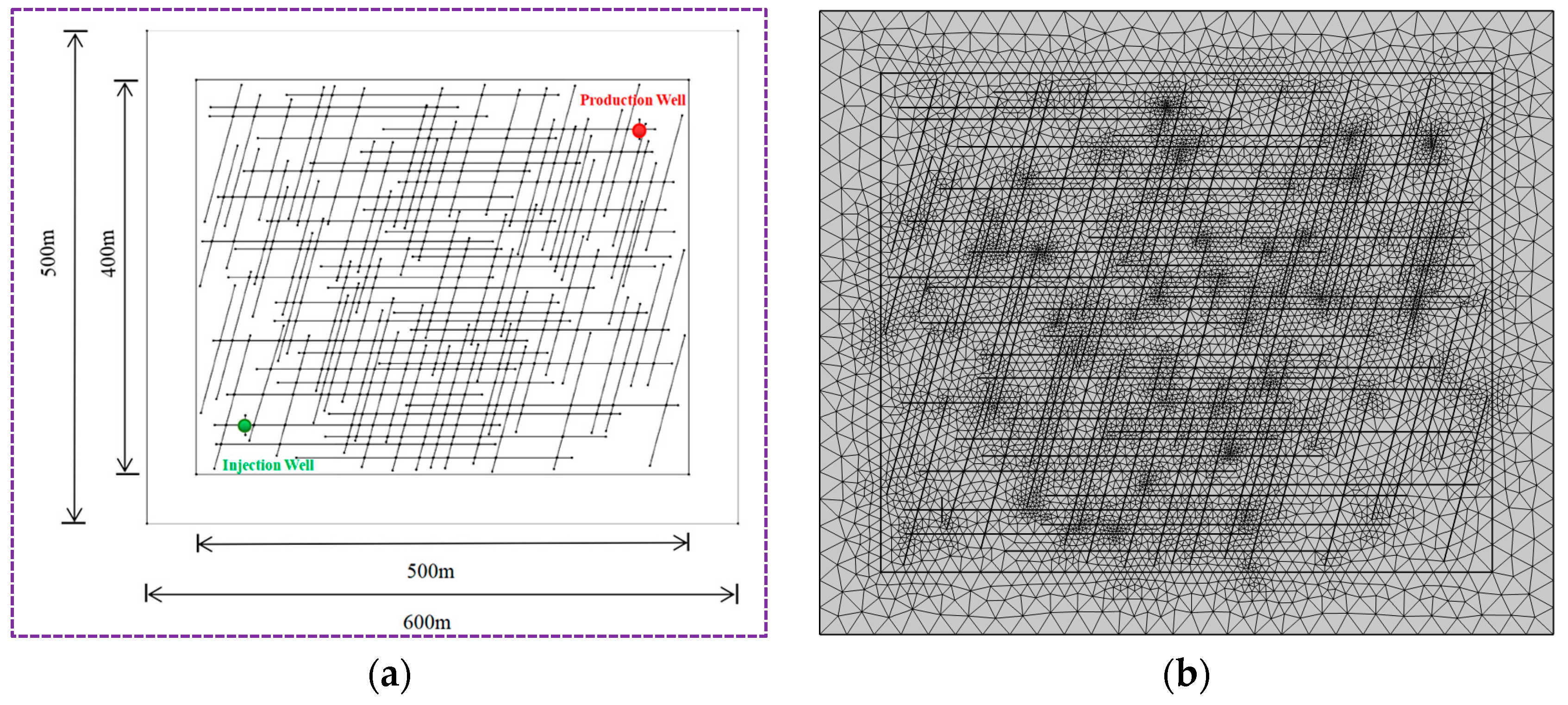
3.1. Introduction to the Numerical Calculation Model

The THM numerical coupling model established in this paper has a size of 600 m × 500 m, and the enhanced geothermal system (EGS) has a size of 500 m × 400 m. In the resulting enhanced geothermal system, 35 horizontal cracks as well as 70 high-angle cracks are included, the spacing between adjacent cracks is set to be between 0.3 m and 50 m, the widths of the natural cracks range from 0.1 mm to 1 mm and the cracks are randomly distributed. The coordinates of the injection wells are (50, 50), the coordinates of production wells are (450, 350), the fracture mesh is divided by a free triangle mesh, and the corresponding numerical computation model is shown in Figure 1.

3.2. Initial and Boundary Calculation Conditions

At the initial moment, for the seepage field of the THM numerical model, all four surfaces of the geothermal reservoir are set as permeable surfaces, the pore pressure of the reservoir is set to 35 MPa, the injection rate of the heat transfer fluid at the injection well is set to 0.05 kg/s, and the pressure of the production well is set to 30 MPa. For the temperature field of the THM numerical model, the four wall surfaces of the geothermal reservoir are set to adiabatic boundaries and, at the initial moment, the temperature at the top of the EGS model is 180 °C, the temperature at the bottom is 212 °C, the injection temperature of the heat exchanger fluid is set to 30 °C, and the temperature gradient is 0.08 °C/m. For the stress field of the THM numerical model, the vertical geostress at the upper boundary and the horizontal geostress at the left boundary are set to 78 MPa and 62 MPa, respectively, and the lower boundary and the right boundary are fixed and constrained by roller supports.
On the basis of the established THM numerical calculation model, the influence of different rock matrix permeability, heat transfer fluid injection velocity, initial fracture width and fracture quantity on heat transfer performance was studied. The heat extraction ratio was used to evaluate the heat transfer performance in the entire fracture network, and the calculation formula is as follows:
η = S p r C r ( T 0 T ) d S S p r C r ( T 0 T i n j ) d S × 100 %
In the above equation, pr is the density of the reservoir rock matrix in [kg/m3]; Cr is the heat capacity of the reservoir rock matrix in [J/(kg·K)]; T0 is the initial temperature of the reservoir rock matrix in [K]; and Tinj is the temperature of the reservoir heat transfer fluid injected into the injection well in [K].

4. Results and Discussion

4.1. Temperature Characteristics During Injection and Production Process

For the THM basic model, the permeability of the rock matrix is 2 × 10⁻¹⁷ m2, the CO2 injection rate is 0.05 kg/s, the number of horizontal seams is 35, the number of high-angle seams is 70, and the fracture widths are all 7 × 10⁻⁴ m. The evolution of temperature throughout the reservoir injection and production wells over different time periods (1 year, 5 years, 15 years and 30 years) was analyzed and the results are shown in Figure 2. As can be seen from Figure 2, heat exchange occurs in both the rock matrix and the fracture network throughout the reservoir rock fracture network. Because in the rock fracture the permeability of the fracture is affected by the CO2 injection pressure, while the permeability of the rock matrix is only related to the change of temperature, the permeability of the fracture is much larger than that of the rock matrix, so the heat exchange efficiency of the fracture is much higher and the expansion of temperature after low-temperature CO2 injection is more obvious along the fracture. A low-temperature region is gradually formed in the fracture and its connecting area, wrapping the high-temperature region of the rock matrix (Figure 2a,b). With the continuous injection of low-temperature CO2, the heat exchange between the high-temperature rock matrix and the low-temperature CO2 in the fissure will make the temperature of the fissure network gradually decrease, the expansion of the temperature of the fissure and the rock matrix will occur along the direction of the connecting production wells, and the temperature transition zone will become more significant. In injection and extraction heat exchange over 15 years and 30 years, the temperature is low in the fissure’s more concentrated area, while the change in the heat exchange of the CO2 in the fissure is slow and the influence of the low-temperature area is greatly reduced. The degree of regional influence is greatly reduced and the heat exchange in the whole reservoir rock fracture network is dominated by the heat exchange in the rock matrix. In addition, after 30 years of CO2 water injection and mining under the same conditions, the low-temperature zone formed by the heat exchange of water is much larger than the low-temperature zone formed by CO2 [40], which demonstrates that CO2 as a heat exchange fluid is more conducive to prolonging the mining life of geothermal reservoirs.

4.2. Influence of Production Well Location on Heat Recovery Performance

In geothermal reservoirs, the locations of production wells have a crucial impact on the heat recovery rate of the injection and extraction process. Therefore, in order to study the influence of different production well locations on the CO2 injection and extraction process, five different production well locations were set up, namely (90, 350), (240, 350), (450, 350), (450, 250) and (450, 110), while the basic model was kept unchanged. The distribution of temperatures after 15 years of injecting CO2 for injection and extraction heat exchange is shown in Figure 3. From the working conditions in Figure 3a–c, it is clear that the horizontal position of the production wells has a significant effect on the distribution of the temperature field. As the production well moves from left to right in the horizontal direction and gradually moves away from the injection well, the fracture connectivity area between the injection well and the production well increases, and the range of the low-temperature area in its vicinity tends to increase. This shows that in the CO2 injection and extraction system of this reservoir, the distance between the production well and the injection well in the horizontal direction is the key factor affecting the degree of heat exchange; the closer the distance, the fewer the connected fractures, the weaker the heat exchange, and the smaller the range of low-temperature area, while the farther the distance, the more the connected fractures, the stronger the heat exchange, and the larger the range of the low-temperature area. Comparing with the working conditions in Figure 3c–e, the change of the vertical position of the production well has less influence on the temperature field, and the range of the low-temperature region in the vicinity of the production well increases slowly as the position of the well moves downward in the vertical direction. In terms of the overall uniformity of the temperature field, the gradient of the temperature distribution of the conditions close to the injection wells varies significantly and the heat exchange is intense and uneven in fewer connected fractures. The temperature distribution of the conditions far from the injection wells is relatively uniform, the heat exchange tends to be balanced, and the stability of the temperature field is improved. Overall, in these five working conditions, the numbers of fracture distributions between the CO2 injection wells and the production wells provide channels for fluid flow and heat transfer. When there are more fractures between the injection and production wells (Figure 3c–e) the contact areas between the injected CO2 and the rock are larger, which is more conducive to promoting heat exchange and the heat can be transferred from the high-temperature rock to the low-temperature fluid more efficiently, resulting in more pronounced variations in temperatures in the regions.
The time-course curves of temperature changes at different production well locations and the changes in heat extraction rates are shown in Figure 4. It can be seen that the production wells at different locations are affected by the distribution of the initial temperature of the reservoir and the relative position of the wells with the injection wells, resulting in differences in the initial temperatures, in which the initial temperatures of the production wells (90, 350), (240, 350) and (450, 350) are relatively low, around 184 °C. The temperature of the production well at (450, 250) is higher (191.86 °C) and the temperature of the production well at (450, 110) is the highest, reaching 202.76 °C. With the injection of CO2, the temperature of each production well shows the evolution trend of gradually decreasing first and then maintaining balance. The larger the relative horizontal distance or the smaller the relative vertical distance between the injection well and the production well, the larger the temperature drop in the production well, so that the production well at (450, 110) has the largest relative horizontal distance and the smallest relative vertical distance from the injection well, so the temperature drop is the fastest, and the temperature drops from 202.76 °C to 202.76 °C after 30 years of injection and extraction. decreasing from 202.76 °C to about 167.22 °C. From the viewpoint of fracture distribution, areas with dense fracture distributions and good connectivity can enhance fluid flow and heat transfer, which is conducive to increasing the heat extraction rate of production wells (e.g., the production wells at (450, 350), (450, 250), (450, 110)). In these zones, production wells can extract heat from the reservoir more efficiently, with faster growth and higher final levels of heat extraction rates. On the contrary, in regions with poor fracture distribution, heat extraction efficiency is limited only by heat transfer from the rock matrix, the heat extraction rate grows slowly and the final level is low (e.g., the production well at (90, 350)).
From the time course evolution of the heat extraction rates of the production wells in Figure 4b, it can be seen that at the same vertical position, the difference in the number of connecting fractures between injection wells and production wells is not large, so changing the vertical positions of production wells has small effects on the heat extraction rates, and the heat extraction rates of the production wells at (450, 100), (450, 250) and (450, 350) after 30 years of injection and extraction are 11.42%, 10.70%, and 10.37%, respectively. At the same horizontal position, the difference in the number of connected fractures between the production wells and injection wells is obvious, the closer to the injection wells the fewer the number of connected fractures, so the rapid transfer of temperature cannot be realized. The temperature drop in the production wells has very little change and after 30 years of injection and extraction heat exchange, the heat extraction rates of the production wells at (90, 350) and (240, 350) are only 4.13% and 5.39%, respectively. Therefore, the appropriate horizontal distance can make the production wells ensure enough heat exchange while avoiding a reduction in heat extraction efficiency due to the excessive influence of low-temperature injection fluid in too close proximity.

4.3. Effect of Different Parameters on Thermal Extraction Performance

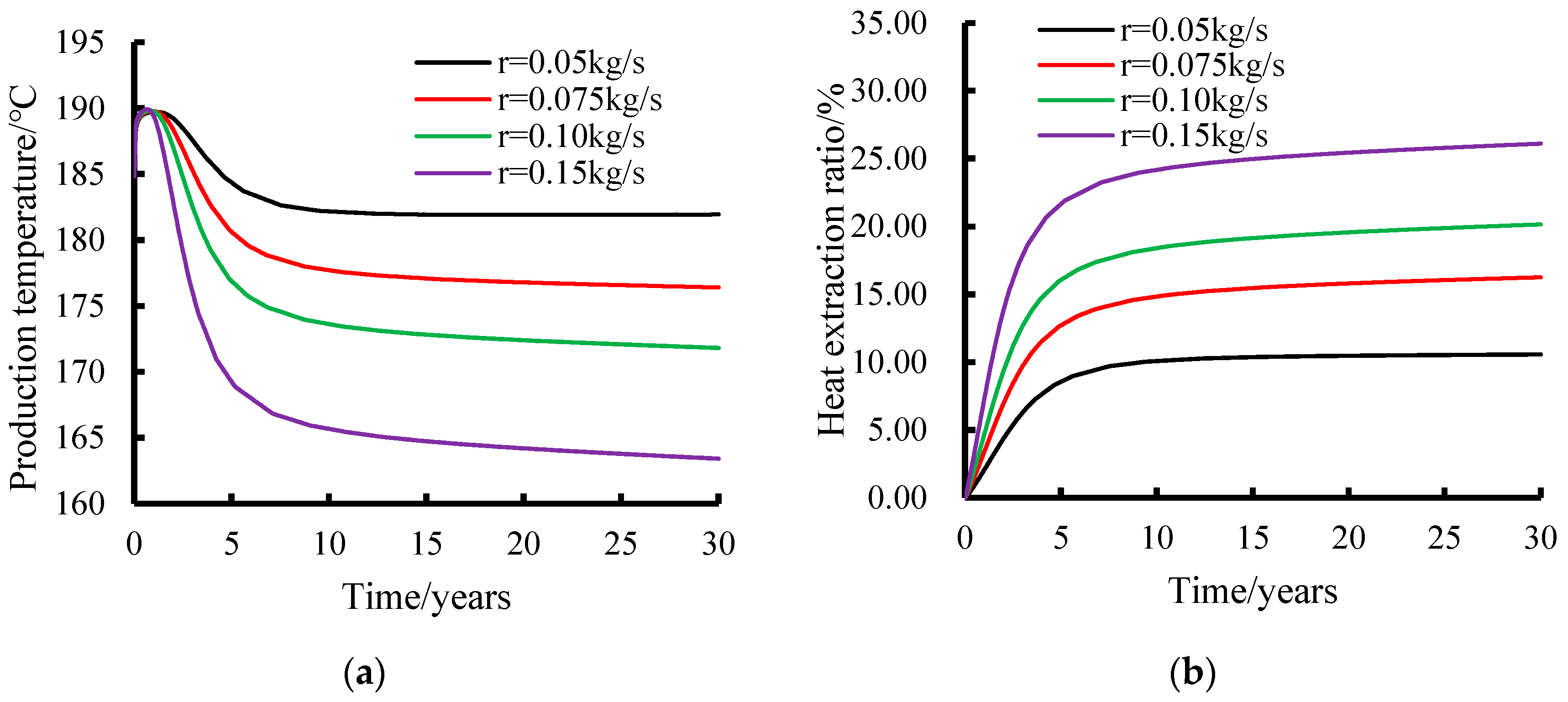
4.3.1. CO2 Injection Rate

In order to study the influence of CO2 injection rate on the heat exchange of reservoir injection and extraction, four working conditions were set on the basis of the basic THM model—namely, r = 0.05 kg/s, r = 0.075 kg/s, r = 0.10 kg/s, r = 0.15 kg/s—and the distribution of the temperature fields after 15 years of injection and extraction under the various conditions is shown in Figure 5. When the CO2 injection rate increases from 0.05 kg/s to 0.075 kg/s, 0.1 kg/s, and 0.15 kg/s, it can be clearly observed that the range in the low-temperature region (blue and light blue parts) is gradually expanded. When the injection rate is 0.05 kg/s, the low-temperature region is relatively small and concentrated near the injection wells. When the injection rate is increased to 0.075 kg/s, the range of the low-temperature region is extended and when the injection rate reaches 0.1 kg/s, the low-temperature region is further extended outward. This indicates that the faster the CO2 injection rate is, the faster and wider the low-temperature CO2 fluid spreads in the reservoir and the wider the range of heat exchange with the high-temperature rock, resulting in expansion in the range of the low-temperature region, which enables the low-temperature CO2 to reach the vicinity of the production well quickly. Meanwhile, with the increase in CO2 injection rate, the low-temperature region was significantly extended and deformed along the fracture direction. This indicates that the CO2 injection rate not only affects the extent of the low-temperature region, but also changes the shape of its distribution in the reservoir, in which the fracture network plays an important role as a guide, and the fluid is more likely to flow along the fracture at high injection rates, thus changing the shape of the temperature field.
The temperatures at the production wells under different CO2 injection rates and the heat extraction rates of the reservoir under each condition were statistically analyzed and the results are shown in Figure 6. From Figure 6a, it can be seen that at the beginning of the injection and extraction process, the initial temperatures of the production wells are basically the same under different CO2 injection rates (all of them were at about 185 °C) and when the low-temperature CO2 has not reached the vicinity of the production wells yet, the thermal heat exchange between the rock matrices will make the temperatures of the production wells rise slowly to reach peak temperatures. When the low-temperature CO2 has not yet reached the vicinity of the production well, the heat exchange between the rock matrix will cause the temperature at the production well to rise slowly to reach peak temperature and, with the increase in CO2 injection time, when the low-temperature CO2 reaches the vicinity of the production well the heat exchange will be carried out quickly, the temperature of the production well will show a rapid decreasing trend in the first stage of all the working conditions, and then decrease slowly. The temperature of the production wells decreases with the increase in CO2 injection rate, such as the temperature of the production wells with an injection rate of 0.15 kg/s decreases the most rapidly, from 185 °C to about 163 °C, within 30 years of injection and extraction. In contrast, the temperatures of the production wells with an injection rate of 0.05 kg/s decrease relatively slowly, the temperature of the production wells is maintained at about 182 °C after 30 years, and the temperature difference between the injection rates of the 0.15 kg/s and 0.05 kg/s production wells after 30 years of injection and extraction was 19 °C. This is because a higher CO2 injection rate means that more low-temperature CO2 fluid enters the reservoir and exchanges heat with the high-temperature rock, which removes heat faster, resulting in a faster temperature drop in the production well. With the injection and extraction process, the heat distribution in the reservoir gradually reaches a relative equilibrium state, and the rate of temperature change decreases after about 15–20 years of injection and extraction, and the temperature decline rate of each curve gradually slows down and stabilizes. From the time evolution curve of the heat extraction rate in the reservoir under different CO2 injection rates in Figure 6b, it can be seen that in the early stage of injection and extraction, the heat extraction rate of each curve grows rapidly, and the faster the CO2 injection rate is, the faster the heat extraction rate grows. For example, the thermal extraction rate with an injection rate of 0.15 kg/s grows to about 21.66% after 5 years of injection and mining, which is significantly larger than that of the case with an injection rate of 0.05 kg/s (the thermal extraction rate is 8.56% after 30 years of injection and mining), and the thermal extraction rate with an injection rate of 0.15 kg/s is 2.5 times higher than that of an injection rate of 0.05 kg/s. This is due to the fact that more CO2 fluid can rapidly exchange heat with the rock at a high injection rate, thus extracting more heat in a short period of time, resulting in a rapid increase in the heat extraction rate. As time continues to pass, the growth in heat extraction rate gradually slows down for each curve. After about 15–20 years, the growth of the curves tends to stabilize, and the heat extraction rate with an injection rate of 0.05 kg/s is finally maintained at about 10.57%, and that with an injection rate of 0.15 kg/s is finally maintained at about 26.11%, which is only an increase of 2.44% compared with the difference in the heat extraction rate after 5 years of injection and mining. This indicates that in the long-term injection and extraction process, although a high injection rate can bring high heat extraction rate growth in the early stages, in the later stages, due to the gradual extraction of reservoir heat, the heat extraction rate has limited space to grow and eventually stabilizes. At the same time, a comparative analysis of the temperature and heat extraction rates when CO2 injection and water [40] are injected and extracted under the same model reveals that, when the injection rate of the heat exchange fluid is 0.1 kg/s, the temperature of the production well when water is the heat exchange fluid decreases from 185 °C to about 50 °C after 30 years of injection and extraction, and the heat extraction rate is 76.2%. When CO2 was the heat transfer fluid, the temperature of the production well was reduced from 185 °C to about 172 °C and the heat extraction rate was 20.2%. Therefore, when water is used as the heat transfer fluid, although the heat extraction rate is higher, the temperature at the production well changes drastically and the decrease is too large, which is unfavorable to the long-term exploitation of the geothermal reservoir; whereas, although the heat extraction rate is lower when CO2 is used as the heat transfer fluid, the temperature change at the production well is smaller, which is favorable to the long-term exploitation of the geothermal reservoir.
Overall, the CO2 injection rate has a significant effect on the temperature of the production well and the heat extraction rate of the reservoir. A higher injection rate can rapidly increase the heat extraction rate at the initial stage, but it will lead to a rapid decrease in the temperature of the production well, while a lower injection rate produces a relatively slow increase in the heat extraction rate, but also a slower decrease in the temperature of the production well. Therefore, in the actual dry hot rock development, it is necessary to consider the production well temperature, heat extraction rate and other factors in order to choose the appropriate CO2 injection rate and realize efficient and stable heat extraction.

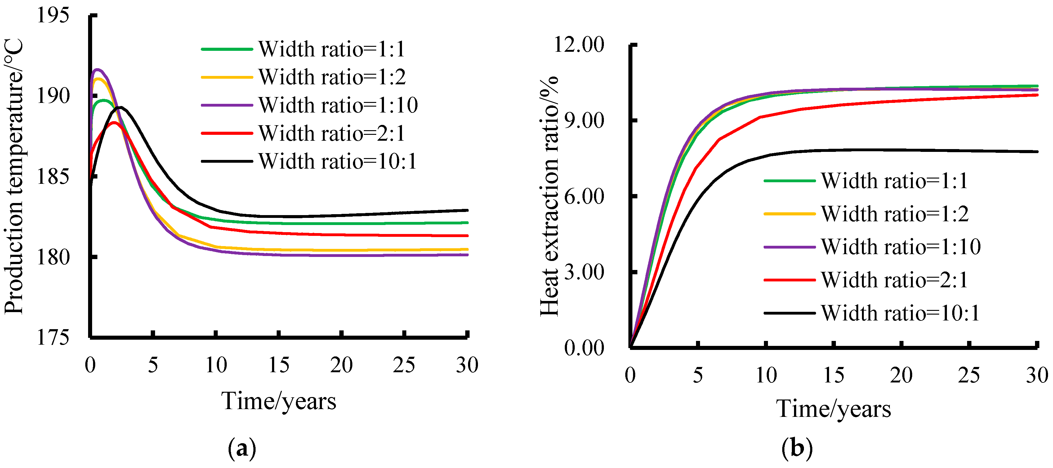
4.3.2. Initial Fracture Width

In the reservoir fracture network, the widths of horizontal and high-angle seams have an important influence on the heat exchange injection and extraction in the whole geothermal system, so in order to analyze the influence of different fracture widths on CO2 injection and extraction heat exchange in the reservoir, based on the basic THM model with a fracture width of 7 × 10⁻⁴ m, the width ratios of the horizontal and high-angle seams were investigated separately as 1/1: 7 × 10⁻⁴ m/7 × 10−4 m, 1/2: 7 × 10⁻⁴ m/14 × 10−4 m, 1/10: 7 × 10⁻⁴ m/7 × 10−3 m, 2/1: 14 × 10−4 m/7 × 10−4 m, 10/1: 7 × 10⁻³ m/7 × 10−4 m and 10/1: 7 × 10⁻³ m/7 × 10−4 m. Comparing the five working conditions, when the horizontal seam width is smaller than the high-angle seam width (Figure 7a–c), the range of the low-temperature region gradually expands in the direction of the high-angle seam inclination with the gradual increase in the high-angle seam width. In the case where the ratio of the width of the horizontal seam to the width of the high-angle seam is 1/10 (Figure 7c), the width of the high-angle seam is greatly increased, the low-temperature region extends outward, and the range of the low-temperature region is significantly expanded. On the contrary, in cases of rations of 2/1 (Figure 7d) and 10/1 (Figure 7e), the width of the horizontal slit increases relatively and the extent of the cryogenic region is reduced compared to cases with larger widths of high-angle slits. Generally speaking, when the width of a high-angle slit is relatively increased, it is more favorable to fluid flow and heat exchange in the vertical direction, which leads to the expansion of the low-temperature region in the vertical direction, significant changes in temperature gradient in the vertical direction, and elongation of the shape of the temperature field in the vertical direction. The relative increase in the width of the horizontal slit has a greater impact on heat exchange and distribution of the temperature field in the horizontal direction, so that expansion of low-temperature regions in the vertical direction may be relatively more restricted, and the ranges of low-temperature regions are narrowed.
The temperature of production wells with different horizontal and high-angle seam width ratios and the heat extraction rate of the reservoir are analyzed and the results are shown in Figure 8. From Figure 8a, it can be seen that the temperatures of production wells with different horizontal and high-angle seam width ratios grow to certain peaks at the beginning of injection and extraction and the sizes of the peak temperatures vary. When the width of the high-angle seam is larger, the peak temperature is also larger, and when the width of the horizontal seam is larger, the peak temperature is also larger. The peak temperatures of the production wells under the five conditions show the following pattern: the temperature of the horizontal seam and the width of the high-angle seam with ratios of 1:10 > 1:2 > 1:1 > 10:1 > 2:1; with the injection and mining, the temperatures of the production wells under the conditions gradually and slowly decrease, and eventually remain basically unchanged. After 30 years of injection and mining, the temperature of the horizontal seam with the ratio of 1:10 width of high-angle seam is 180.14 °C, and the temperature of the horizontal seam with the ratio of 10:1 width of high-angle seam is 182.9 °C, which indicates that the width of high-angle seam is relative to the width of horizontal seam (the condition of 1:10). The heat exchange of low-temperature fluid in the vertical direction is more powerful and it can take away the heat faster, resulting in the temperature of the production well decreasing faster, while the temperature of the horizontal seam with a relatively larger width (the condition of 10:1) decreases slowly. At this time, the stabilized temperatures of the production wells under the five conditions are, in descending order, as follows: the ratio of the width of the horizontal seam to that of the high-angle seam is 1:10 < 1:2 < 2:1 < 1:1 < 10:1.
As can be seen from the time evolution curve of the heat extraction rates of reservoirs with different horizontal slit to high-angle slit width ratios in Figure 8b, the heat extraction rate of each condition grows rapidly in the early stages of injection and extraction. The heat extraction rate of the horizontal seam to high-angle seam width ratio of 1:10 grows the fastest, increasing to 10.06% in 10 years, which is only 0.129% higher than that of the horizontal seam to high-angle seam width ratio of 1:1. The heat extraction rate of the width ratio of 10:1 grows slower, increasing to only 7.59% in 10 years. The reason for this is that when the width of the high-angle slit is relatively large, it is more favorable to vertical fluid flow and heat transfer, which makes it possible to extract more heat in a short time and the heat extraction rate grows faster, while when the width of the horizontal slit is relatively large, the heat transfer is relatively limited at the initial stage and the heat extraction rate grows slower. As the time continues to pass, the increase in heat extraction rate gradually slows down after 15–30 years. The heat extraction rate is basically the same after 30 years of injection and mining under the conditions of 1:10, 1:2 and 1:1 for the width ratio of horizontal seam to high-angle seam, and the heat extraction rate is maintained at about 10%. As the width of the horizontal seam increases, the heat extraction rate is only 7.77% for the condition of 10:1 for the width ratio of the horizontal seam to high-angle seam after 30 years of injection and mining. It can be seen that when the width of the high-angle seam is relatively large, the vertical heat exchange is strong, the temperature of the production well decreases quickly, and the heat extraction rate grows rapidly at the initial stage, but at the later stage of injection and mining, it is basically the same as the heat extraction rate when the width of the horizontal seam is equal to the width of the high-angle seam. When the width of the horizontal seam is relatively large, the temperature of the production well decreases slowly, and the growth of the heat extraction rate is slower at the initial stage, with a lower stabilization value at the later stage. Therefore, when the ratio of the width of horizontal slit and high-angle slit is less than 1, the smaller the ratio is, the faster the temperature drop at the production well, but the effect on the heat extraction rate of the reservoir is not obvious. When the ratio of the width of the horizontal slit and the high-angle slit is greater than 1, the greater the ratio is, the slower the temperature drop in the production well, and the lower the heat extraction rate of the reservoir.

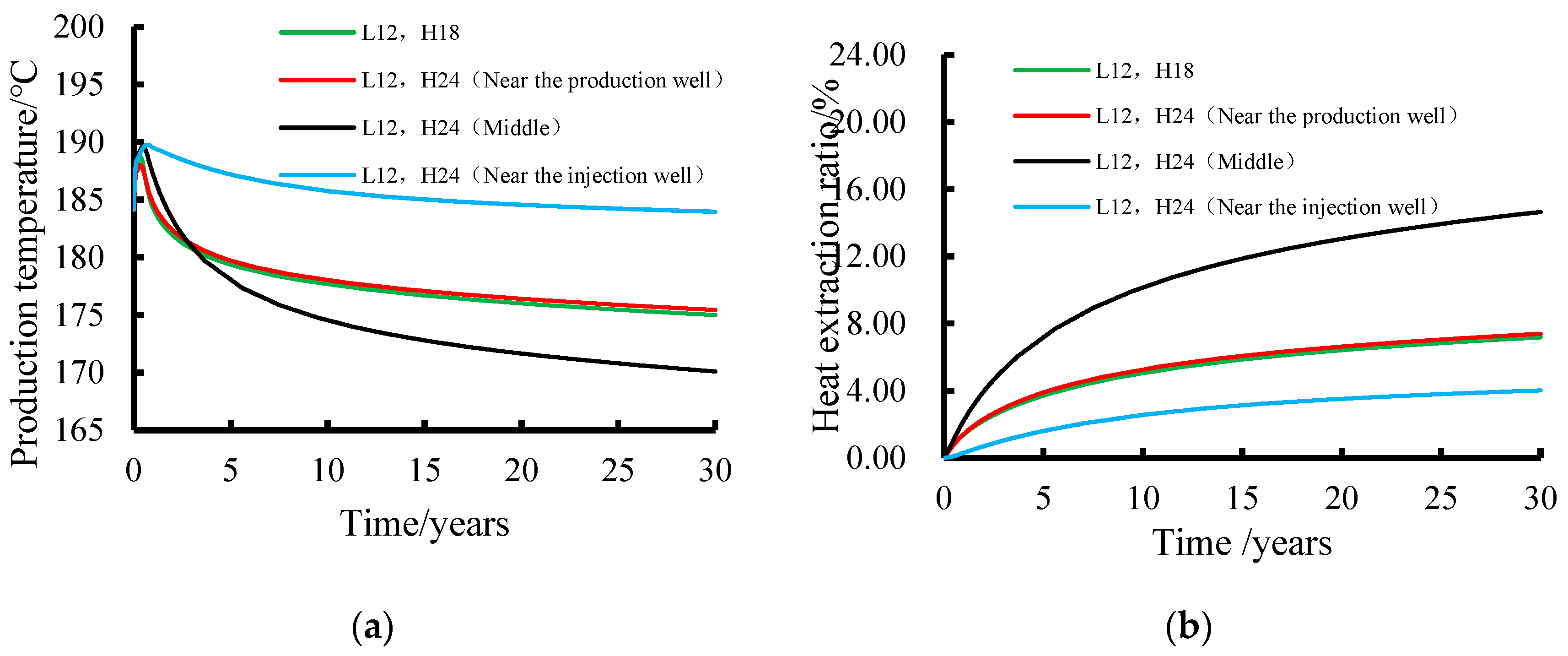
4.3.3. Number of High-Angle Fractures

In order to study the influence of the increased amount of high-angle fractures at different locations on the reservoir CO2 injection and extraction heat transfer, six high-angle fractures were added on top of 12 horizontal fractures and 18 high-angle fractures, and the locations of the fractures were set close to the production wells, close to the injection wells, and between the production wells and the injection wells, respectively. By studying the temperature evolution process of the basic model with 12 horizontal seams (L12), 18 high-angle seams, and the model with the added high-angle seams close to the production wells, the injection wells, and located between the injection wells and the production wells after 20 years of injection and extraction, the temperature fields in each case were calculated and are shown in Figure 9. It can be seen in Figure 9 that, when the added high-angle seams are close to the production wells, they provide more channels for the flow and heat exchange of low-temperature fluid toward the production well, which makes the temperature near the production well decrease, the change in temperature gradients near the production wells increase, and the range of low-temperature regions gradually increase. When the high-angle fracture is close to the injection well, it accelerates the heat exchange around the injection well, which makes the low-temperature region spread further around the injection well and the temperature gradient changes around the injection well are obvious, especially in the vicinity of the newly added high-angle fractures. The temperature changes more significantly within a short distance, reflecting a significant increase in the intensity of heat exchange in the region. When the high-angle fracture is located between the production well and the injection well, the increased fracture improves the connectivity between the injection well and the production well, provides more heat transfer channels for the intermediate region, promotes the heat exchange between the production well and the injection well, and thus expands the low-temperature range of the region, which results in the low-temperature region expanding significantly in the connecting region between the production well and the injection well and forming a narrower and longer low-temperature region. It can be seen that the increase in high-angle fractures at different locations has a significant effect on the temperature field of CO2 injection and extraction heat exchange in the reservoir. The increase in high-angle fractures changes the extent of the low-temperature region, the temperature gradient, and the shape of the temperature field, which in turn affects the heat exchange process within the reservoir.
The temperatures of the production well and the heat extraction rates of the reservoir rock after adding the number of high-angle seams at different locations in the basic model and as described above mentioned are shown in Figure 10. With the CO2 injection and extraction of heat exchange, the temperature of the production well firstly rises to a certain peak and then decreases for a short time in all the conditions, as shown in Figure 10a. The peak temperature of the production well in the order from the largest to the smallest is the temperature of the added high-angle seam, which is near the injection well. The added high-angle seam is located between the production well and the injection well (the basic model) and the added high-angle seam is near the production well. The decreasing trends in the production well temperatures are also different in each case. For the cases with the basic model, where the added high-angle slit is located near the production well and between the production well and the injection well, the temperature of the production well decreases rapidly from the peak temperature, while the temperature of the production well decreases slowly in cases with the added high-angle slit located in the injection well. The decrease is much smaller in the other three cases. In terms of the temperature drop in the production well in each case, the temperature in the case where the added high-angle seam is located between the production well and the injection well decreases the fastest, from 184 °C to 174 °C after 10 years of injection, while the temperature of the basic model and the case where the added high-angle seam is located near the production well have nearly the same decreasing tendency and magnitude, from 184 °C to 177.7 °C and 178.1 °C, respectively. The temperature of the added high-angle seam near the injection welldecreases the slowest, from 190 °C to 185.77 °C only.
From the reservoir heat extraction rate (Figure 10b), the growth of heat extraction rate for each condition gradually slowed down with the CO2 injection and extraction heat exchange. The heat extraction rate of the condition where the increased high-angle fracture is located between the production well and the injection well grows the fastest, increasing to about 13% in 20 years, which is 6.6% higher than that of the basic model. The heat extraction rates of the increased high-angle fracture near the production well and those of the basic model are not much different after 20 years of CO2 injection, at 6.6% and 6.4%, respectively. The heat extraction rate of the high-angle fracture located near the injection well increases the slowest, and the heat extraction rate after 20 years of CO2 injection is only 3.5%, which is still 2.9% lower than that of the basic model. Analyzing the difference between the temperature of the production well and the heat extraction rate of the reservoir under each working condition, it can be seen that when the high-angle fracture is located between the production well and the injection well, it provides more effective channels for heat transfer, promotes heat exchange between the production well and the injection well, and makes it possible to extract more heat in a short period of time Therefore, the temperature at the production well is the lowest, and the heat extraction rate is the fastest. When the high-angle fracture is close to the production well the high-angle fracture increases in the vicinity of the production well and the heat extraction rate is the slowest, while an increase in the number of high-angle fractures near the production well has no obvious effect on the temperature change and heat extraction rate of the production well. When the high-angle fractures are close to the injection well, although the increase in the number of fractures and connectivity around the injection well accelerates the heat exchange around the injection well, the efficiency of the heat transfer to the production well is still relatively low and the growth in the heat extraction rate is slower. Therefore, in the actual CO2 injection and extraction heat exchange project, it is necessary to consider the temperature of the production well, the heat extraction rate and other factors and arrange the locations of the high-angle fissures reasonably to achieve efficient and stable heat extraction.

5. Summary and Conclusions

In this paper, a THM model applicable to CO2 injection and extraction heat exchange was established, the temperature characteristics during CO2 injection and production were investigated by numerical simulation, and the influence of the locations of production wells as well as the rate of CO2 injection, initial fracture width, and number of high-angle fissures on the performance of heat extraction of CO2 in the complex fracture network were analyzed. The conclusions obtained were as follows:
(1)
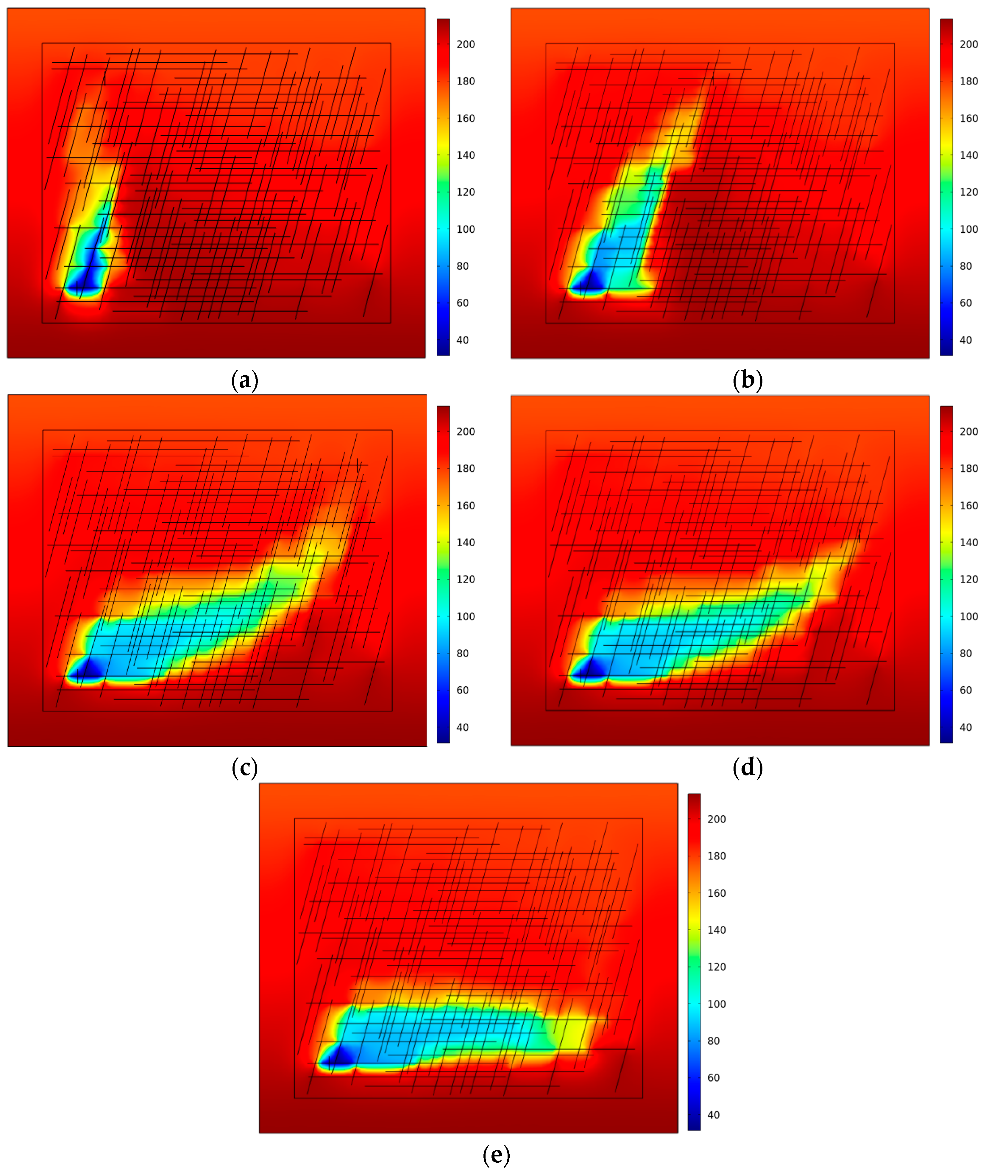
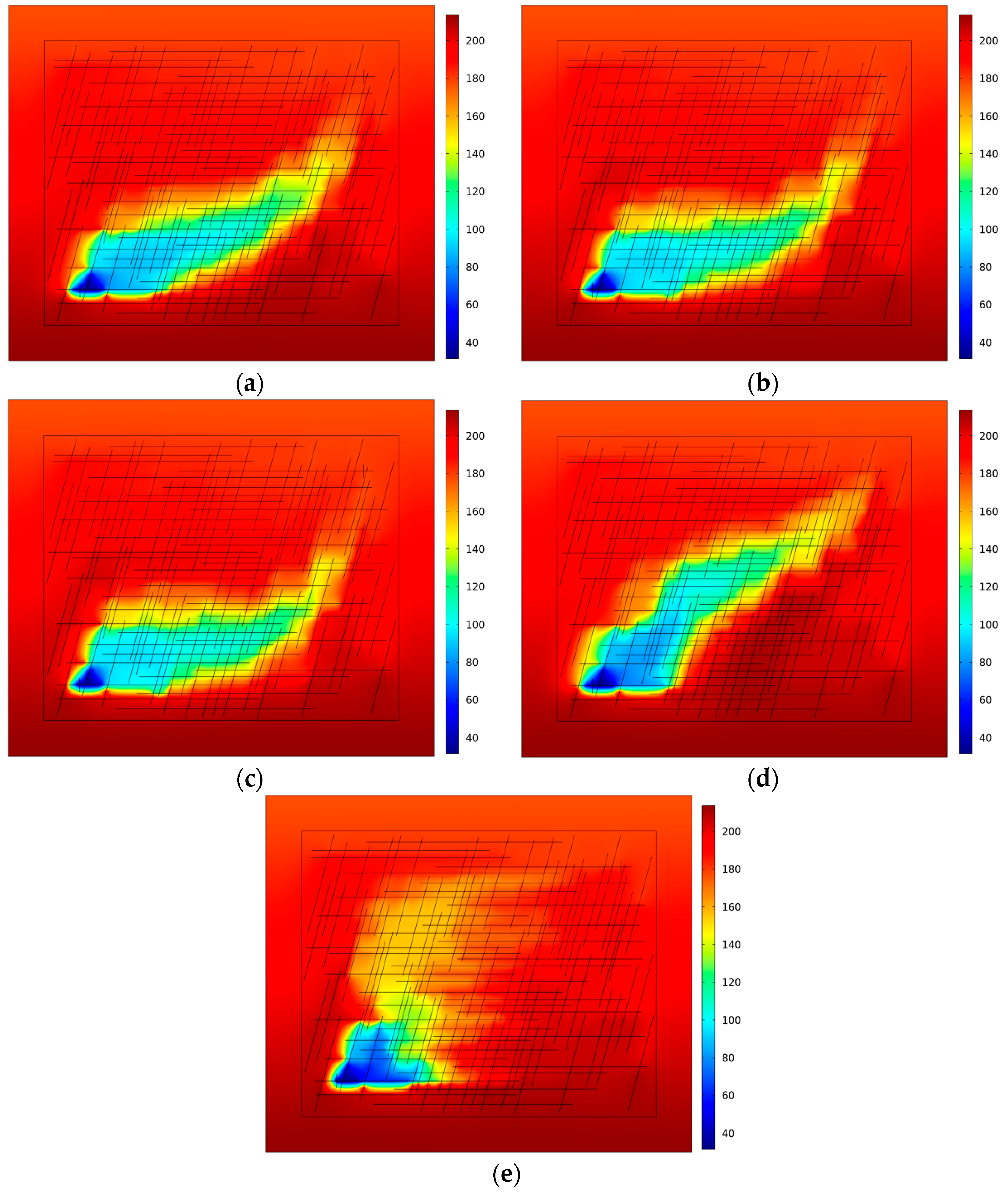
In the reservoir rock fracture network, the fracture heat exchange efficiency is higher than that of rock matrix, the temperature mainly expands along the fracture after low-temperature CO2 injection, a low-temperature zone is gradually formed in the reservoir fracture and its connecting zone, and the heat exchange of the reservoir in the later stages is dominated by the rock matrix. Under the same conditions of injection and extraction for 30 years, the influence range of the low-temperature zone formed by using CO2 as the injection and extraction fluid is much less than that formed by using water as the injection and extraction fluid. Therefore, CO2 injection heat exchange is more conducive to prolonging the life of geothermal reservoirs.
(2)
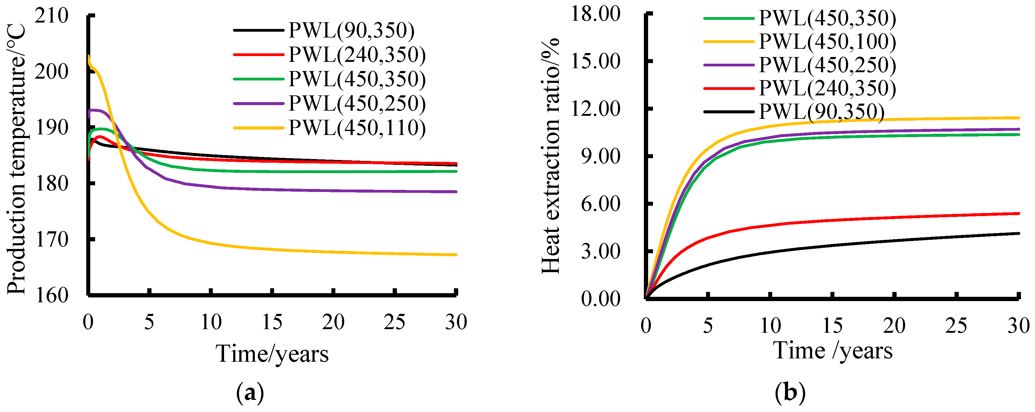
The horizontal position of the production wells has a significant effect on temperature field distribution. The farther the horizontal distance from the injection wells, the better the fracture connectivity, the stronger the heat exchange and the larger the range of the low-temperature zones. Changing of the vertical position of the production wells has a smaller effect on the temperature fields and the better the connectivity between the production wells and the injection wells at different vertical positions, the higher the heat extraction rate.
(3)
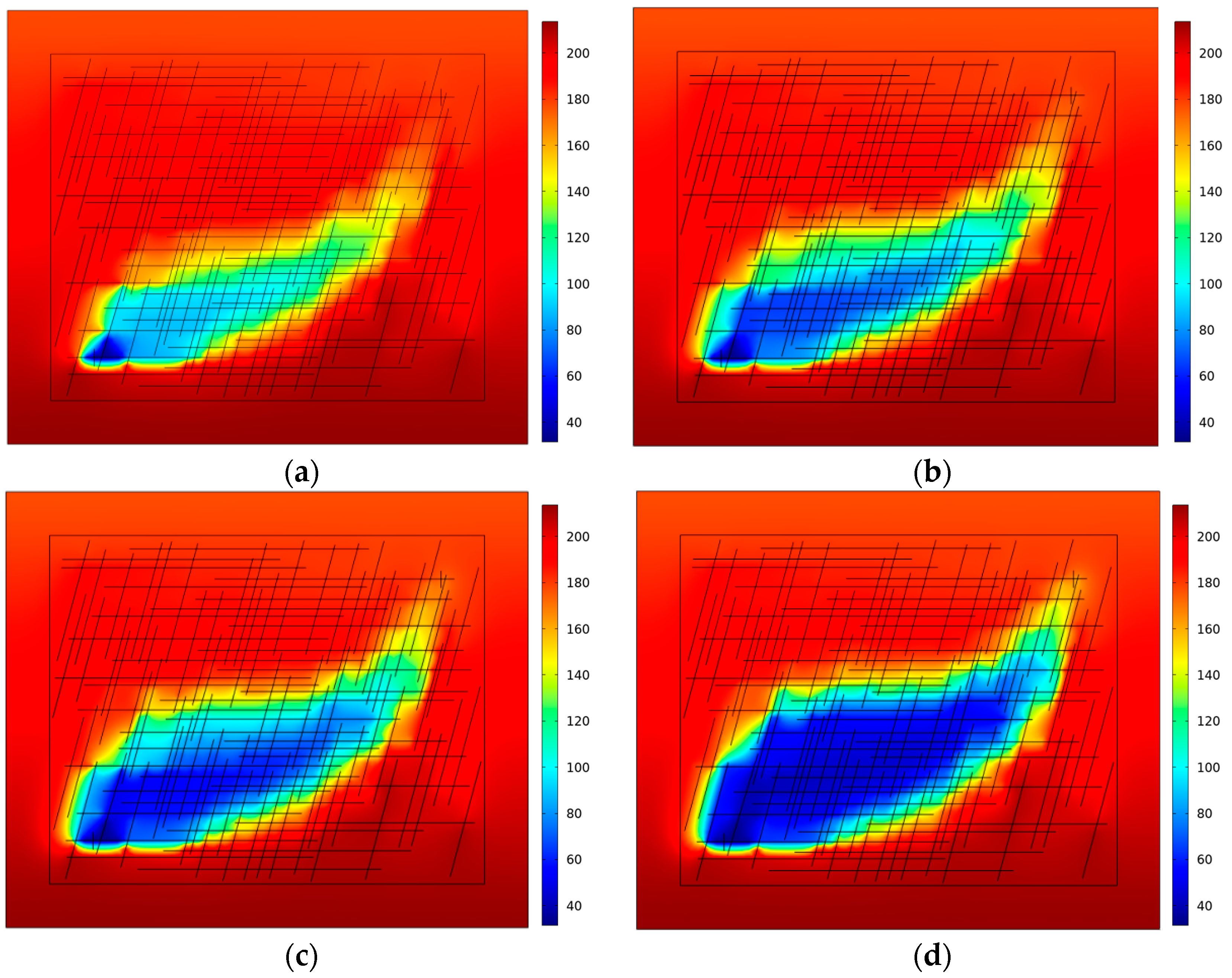
The faster the CO2 injection rate is, the larger the range of low-temperature area there is, the more obvious the change in distribution shape is and the easier it is to flow along the fracture, The rate of temperature drop in the production well and the growth rate of the heat extraction rate of the reservoir at the early stages of injection and extraction increase with the increase in the injection rate, and then the changes in the temperature of the production well and the heat extraction rate of the reservoir tend to be stable in the later stages.
(4)
The increase in high-angle fracture width facilitates vertical fluid flow and heat exchange, which promotes the vertical extension of low-temperature regions and the elongation of temperature fields along the vertical direction. The temperature of production wells decreases quickly and the heat extraction rate increases rapidly at the initial stage, while the increase in horizontal fracture width is opposite to this law. In addition, the increase in high-angle fractures at different locations will change the range, temperature gradient and shape of the low-temperature region, which in turn affects the heat exchange, with the fastest growth of the heat extraction rate occurring when it is located between the production wells and the injection wells, is less obvious near the production wells, and slower near the injection wells.

Author Contributions

Conceptualization, Y.L.; Methodology, X.Z.; Software, Y.Z. (Yizhong Zhao); Validation, P.Z.; Formal analysis, Y.Z. (Yinghui Zhu); Investigation, Y.W.; Resources, X.H. All authors have read and agreed to the published version of the manuscript.

Funding

This research was funded by the Science and Technology Department of Sichuan Province (Grant Nos. 2021YFH0048 and 2021YFH0118) and the Research Project of the Geothermal Foundation of the Science and Technology Department of Sinopec (P25095).

Data Availability Statement

The original contributions presented in the study are included in the article, further inquiries can be directed to the corresponding author.

Acknowledgments

The authors would like to thank the Science and Technology Department of Sichuan Province and the Science and Technology Department of Sinopec for providing financial support for this research. We would like to express our gratitude to all colleagues and collaborators who have directly or indirectly contributed to this research.

Conflicts of Interest

Authors Yuguo Liu, Yizhong Zhao, Xiaolong Zhao and Yinghui Zhu were employed by the Sinopec Shengli Oilfield Company. The remaining authors declare that the research was conducted in the absence of any commercial or financial relationships that could be construed as a potential conflict of interest.

References

  1. Wang, J.; Li, P.-J.; Zhang, T.; Zhu, C.-Y.; Zhang, Y.-N. Simulation of CO2 and water convective heat transfer in single fracture of practical rock sample. Chem. Ind. Eng. Prog. 2024, 43, 5403–5414. [Google Scholar]
  2. Zhao, P.; Zhu, H.-Y.; Li, G.-S.; Chen, Z.; Chen, S.-J.; Shang Guan, S.-T.; Qi, X.-F. Large-scale physical simulation of injection and production of hot dry rock in Gonghe Basin, Qinghai Province, China. Petrol. Explor. Dev. 2024, 51, 646–654. [Google Scholar] [CrossRef]
  3. Hui, Z.; Feng, Z.-J.; Wu, Z.-S.; Shi, X.-D. Experimental Study on Seepage and Heat Transfer of Sandstone with Single Fracture Under Multi-Level Confining Pressure. Min. Res. Dev. 2020, 40, 105–110. [Google Scholar]
  4. He, Y.-Y.; Bai, B.; Hu, S.-B.; Li, X.-C. Effects of surface roughness on the heat transfer characteristics of water flow through a single granite fracture. Comput. Geotech. 2016, 80, 312–321. [Google Scholar]
  5. Luo, Y.-F.; Xu, W.-L.; Lei, Y.-D.; Wu, P.; Qin, G.-X.; Ba, R.-S. Experimental study of heat transfer by water flowing through smooth and rough rock fractures. Energy Rep. 2019, 5, 1025–1029. [Google Scholar]
  6. Yao, J.; Zhang, X.; Sun, Z.-X.; Huang, Z.-Q.; Liu, J.-R.; Li, Y.; Xin, Y.; Yan, X.; Liu, W.-Z. Numerical simulation of the heat extraction in 3D-EGS with thermal-hydraulic-mechanical coupling method based on discrete fractures model. Geothermics 2018, 74, 19–34. [Google Scholar]
  7. Song, G.-F.; Song, X.-Z.; Xu, F.-Q.; Li, G.-S.; Wang, G.-S.; Ji, J.-Y.; Shi, Y. Numerical parametric investigation of thermal extraction from the enhanced geothermal system based on the thermal-hydraulic-chemical coupling model. J. Clean. Prod. 2022, 352, 131609. [Google Scholar]
  8. Du, X.; Jiang, Y.-X.; Yang, F.; Lu, D.-T. Thermo-hydro-mechanical fully coupled model for enhanced geothermal system and numerical solution method based on finite volume method. Renew. Energy. 2024, 237, 121559. [Google Scholar]
  9. Wang, T.-Y.; Zhou, X.-X.; Li, G.-S.; Wang, Y.; Tian, S.-Z. Geothermal development model of multilateral radial well and its heat extraction effect analysis based on thermal-hydraulic-mechanical coupling. Nat. Gas Ind. 2023, 43, 133–144. [Google Scholar]
  10. Sun, Z.-X.; Zhang, X.; Xu, Y.; Yao, J.; Wang, H.-X.; Lv, S.-H.; Sun, Z.-L.; Huang, Y.; Cai, M.-Y.; Huang, X.-X. Numerical simulation of the heat extraction in EGS with thermal-hydraulic-mechanical coupling method based on discrete fractures model. Energy 2017, 120, 20–33. [Google Scholar]
  11. Tsang, C.-F.; Bernier, F.; Davies, C. Geohydromechanical processes in the excavation damaged zone in crystalline rock, rock salt, and indurated and plastic clays-in the context of radioactive waste disposal. Int. J. Rock Mech. Min. Sci. 2005, 42, 109–125. [Google Scholar]
  12. Gutierrez, M.; Makurat, A. Coupled HTM modellingof cold water injection in fractured hydrocarbon reservoirs. Int. J. Rock Mech. Min. Sci. 1997, 34, 113.e1–113.e15. [Google Scholar]
  13. Chen, J.-L.; Jiang, F.M. Designing multi-well layout for enhanced geothermal system to better exploit hot dry rock geothermal energy. Renew. Energ. 2015, 74, 37–48. [Google Scholar]
  14. Salimzadeh, S.; Nick, H.-M.; Zimmerman, R.-W. Thermoporoelastic effects during heat extraction from low-permeability reservoirs. Energy 2018, 142, 546–558. [Google Scholar]
  15. Duan, X.-Y.; Huang, D.; Lei, W.-X.; Chen, S.-C.; Huang, Z.-Q.; Zhu, C.-Y. Investigation of Heat Extraction in an Enhanced Geothermal System Embedded with Fracture Networks Using the Thermal-Hydraulic-Mechanical Coupling Model. Energies 2023, 16, 3758. [Google Scholar] [CrossRef]
  16. Cheng, Y.-X.; Zhang, Y.-J.; Yu, Z.-W.; Hu, Z.-J.; Yang, Y.-X. An investigation on hydraulic fracturing characteristics in granite geothermal reservoir. Eng. Fract. Mech. 2020, 237, 107252. [Google Scholar]
  17. Yoshioka, K.; Pasikki, R.; Stimac, J. A long term hydraulic stimulation study conducted at the Salak geothermal field. Geothermics 2019, 82, 168–181. [Google Scholar]
  18. Park, S.; Xie, L.-M.; Kim, K.; Kwon, S.; Min, K.; Choi, J.; Yoon, W.; Song, Y. First hydraulic stimulation in fractured geothermal reservoir in Pohang PX-2 Well. Procedia Eng. 2017, 191, 829–837. [Google Scholar]
  19. Pruess, K. Enhanced geothermal systems (EGS) using CO2 as working fluid: A novel approach for generating renewable energy with simultaneous sequestration of carbon. Geothermics 2006, 35, 351–367. [Google Scholar]
  20. Xu, R.-N.; Zhang, L.; Zhang, F.-Z.; Jiang, P.-X. A review on heat transfer and energy conversion in the enhanced geo thermal systems with water/CO2 as working fluid. Int. J. Energy Res. 2015, 39, 1722–1741. [Google Scholar]
  21. Na, J.; Xu, T.-F.; Yuan, Y.-L.; Feng, B.; Tian, H.-L.; Bao, X.-H. An integrated study of fluid-rock interaction in a CO2-based enhanced geothermal system: A case study of Songliao Basin, China. Appl. Geochem. 2015, 59, 166–177. [Google Scholar] [CrossRef]
  22. Qiao, Z.-L.; Cao, Y.; Tang, Y.-F.; Si, F.-Q. Numerical Analysis of Membrane-Absorption Separation for Supercritical Carbon Dioxide and Water Mixture of Plume Geothermal Power Generation Systems. Energy Convers. Manag. 2020, 208, 112609. [Google Scholar] [CrossRef]
  23. Xu, Z.-P.; Tan, Y.-F.; Zhang, T.-T.; Li, Z.-Y. Research Review on Supercritical Carbon Dioxide for Geothermal Extraction. Gas Heat 2024, 44, 16–27. [Google Scholar]
  24. Chen, S.-J.; Pan, Y.; Sun, L.; Si, Y.; Liang, F.; Gao, L. Mechanism of enhanced oil recovery by CO2 combination flooding in low permeability and high pour-point reservoir. Petrol. Reserv. Eval. Dev. 2021, 11, 823–830. [Google Scholar]
  25. Liu, Y.-L.; Xu, T.-F.; Yuan, Y.-L.; Feng, B.; Tang, X.-H.; Liu, X.; Cui, Z.-P. A laboratory study on fracture initiation and propagation of granite under cyclic-in jection hydraulic fracturing. J. Petrol. Sci. Eng. 2022, 212, 110278. [Google Scholar] [CrossRef]
  26. Wang, D.-B.; Bian, X.-B.; Qin, H.; Sun, D.-L.; Yu, B. Experimental investigation of mechanical properties and failure behavior of fluid-saturated hot dry rocks. Nat. Resour. Res. 2021, 30, 289–305. [Google Scholar] [CrossRef]
  27. Shi, Y.; Song, X.-Z.; Li, G.-S.; Xu, F.-Q.; Cui, Q.-L. Comparison of heat extraction performance between CO2 and water in a multilateral-well geothermal system. Nat. Gas Ind. 2021, 41, 179–190. [Google Scholar]
  28. Ren, S.-R.; Cui, G.-D.; Li, D.-X.; Zhuang, Y.; Li, X.; Zhang, L. Development of geothermal energy from depleted high temperature gas reservoir via supercritical CO2 injection. J. China Univ. Petrol. 2016, 40, 91–98. [Google Scholar]
  29. Chen, Y.; Ma, G.-W.; Wang, H.-D.; Li, T.; Wang, Y. Application of carbon dioxide as working fluid in geothermal development con sidering a complex fractured system. Energy Convers. Manag. 2019, 180, 1055–1067. [Google Scholar] [CrossRef]
  30. Wang, Y.; Li, T.; Ma, G.-W. Numerical analysis of heat mining and geological carbon sequestration in supercritical CO2 circulating enhanced geothermal systems inlayed with com plex discrete fracture networks. Energy 2019, 173, 92–108. [Google Scholar] [CrossRef]
  31. Li, Q.; Li, Q.-C.; Cao, H.-Q.; Wu, J.-J.; Wang, F.; Wang, Y.-L. The Crack Propagation Behaviour of CO2 Fracturing Fluid in Unconventional Low Permeability Reservoirs: Factor Analysis and Mechanism Revelation. Processes 2025, 13, 159. [Google Scholar] [CrossRef]
  32. Li, Q.-C.; Li, Q.; Wu, J.-J.; Li, X.-Z.; Li, H.-B.; Cheng, Y.-F. Wellhead Stability During Development Process of Hydrate Reservoir in the Northern South China Sea: Evolution and Mechanism. Processes 2025, 13, 40. [Google Scholar] [CrossRef]
  33. Xu, C.-S.; Dowd, P.A.; Tian, Z.-F. A simplified coupled hydro-thermal model for enhanced geothermal systems. Appl. Energy 2015, 140, 135e45. [Google Scholar]
  34. Yan, B.-C.; Xu, Z.; Manojkumar, G.; Tariq, Z.; Sun, S.-Y.; Finkbeiner, T. Physics-informed machine learning for reservoir management of enhanced geothermal systems. Geoenergy Sci. Eng. 2024, 234, 212663. [Google Scholar]
  35. Song, X.-Z.; Shi, Y.; Li, G.-S.; Yang, R.-Y.; Wang, G.-S.; Zheng, R.; Li, J.-C.; Lyu, Z.-H. Numerical simulation of heat extraction performance in enhanced geothermal system with multilateral wells. Appl. Energy 2018, 218, 325–337. [Google Scholar]
  36. Zhang, X.; Huang, Z.-W.; Li, G.-S.; Wu, X.-G.; Wang, T.-Y.; Zhou, X.-X. Enhancing reservoir stimulation and heat extraction performance for fractured geothermal reservoirs: Utilization of novel multilateral wells. Energy 2024, 291, 130410. [Google Scholar]
  37. Zhao, P.; Liu, J.; Elsworth, D. Numerical study on a multifracture enhanced geothermal system considering matrix permeability enhancement induced by thermal unloading. Renew. Energy 2023, 203, 33–44. [Google Scholar] [CrossRef]
  38. Liu, D.-D.; Wei, L.-X.; Xu, G.-Y.; Xiang, Y.-Y. Simulation of seepage and heat transfer in 3D fractured rock mass based on fracture continuum method. Rock Soil Mech. 2023, 44, 7. [Google Scholar]
  39. Guo, T.-K.; Zhang, Y.-L.; Zhang, W.; Niu, B.-L.; He, J.-Y.; Chen, M.; Yu, Y.; Xiao, B.; Xu, R.-L. Numerical simulation of geothermal energy productivity considering the evolution of permeability in various fractures. Appl. Therm. Eng. 2022, 201, 117756. [Google Scholar]
  40. Peng, J.; Zhao, P.; Zhu, H.-Y.; Chen, S.-J.; Xian, H.-Y.; Ni, T. Simulating the impact of complex fracture networks on the heat extraction performance of hot-dry rock masses. Nat. Gas Ind. B 2024, 11, 196–212. [Google Scholar]
Figure 1. Schematic diagram of the numerical model and mesh delineation: (a) numerical model and (b) model meshing.
Energies 18 01606 g001
Figure 2. Evolution of heat exchange temperature (°C) for CO2 at different injection times and for 30 years of water injection and extraction: (a) CO2 injection heat transfer year 1; (b) CO2 injection heat transfer year 5; (c) CO2 injection heat transfer year 15; (d) CO2 injection heat transfer year 30; and (e) 30th year of heat transfer for water injection and extraction.
Energies 18 01606 g002aEnergies 18 01606 g002b
Figure 3. Reservoir temperature evolution (°C) for 15 years of injection and extraction at different production well locations: (a) production well locations (90, 350); (b) production well locations (240, 350); (c) production well locations (450, 350); (d) production well locations (450, 250); and (e) production well location (450, 110).
Energies 18 01606 g003
Figure 4. Time course evolution of production temperatures and reservoir heat extraction rates at different production wells: (a) production temperature at different production well locations and (b) reservoir heat extraction rate at different production well locations.
Energies 18 01606 g004
Figure 5. Reservoir temperature evolution (°C) for 15 years of injection and extraction heat exchange at different CO2 injection rates: (a) r = 0.05 kg/s; (b) r = 0.075 kg/s; (c) r = 0.1 kg/s; and (d) r = 0.15 kg/s.
Energies 18 01606 g005
Figure 6. Time evolution of production well temperature and reservoir heat extraction rate at different CO2 injection rates: (a) production temperatures of production wells at different CO2 injection rates and (b) reservoir heat extraction rates at different CO2 injection rates.
Energies 18 01606 g006
Figure 7. Reservoir temperature evolution (°C) over 15 years with different horizontal and high-angle seam width ratios for injection and extraction heat exchange: (a) 1/1: 7 × 10⁻⁴ m/7 × 10−4 m; (b) 1/2: 7 × 10⁻⁴ m/14 × 10−4 m; (c) 1/10: 7 × 10⁻⁴ m/7 × 10−3 m; (d) 2/1: 14 × 10−4 m/7 × 10−4 m; and (e) 10/1: 7 × 10⁻³ m/7 × 10−4 m.
Energies 18 01606 g007
Figure 8. Time evolution of production well temperatures and reservoir heat extraction rates for different horizontal seam and high-angle seam width ratios: (a) production temperature of production wells with different horizontal and high-angle seam widths and (b) reservoir heat extraction rate with different horizontal and high-angle seam widths.
Energies 18 01606 g008
Figure 9. The 15-year reservoir temperature evolution (°C) at different locations of injection and extraction heat exchange where the added high-angle seam is located: (a) L12 and H18 (basic model for such conditions); (b) L12 and H24 (near production wells); (c) L12 and H24 (between injection wells production wells); (d) L12 and H24 (near injection wells).
Energies 18 01606 g009
Figure 10. Time evolution of production well temperatures and reservoir heat extraction rates for different horizontal and high-angle seam width ratios: (a) production temperature of production wells at different locations of the increased high-angle seams and (b) reservoir heat extraction rates at different locations of the increased high-angle seams.
Energies 18 01606 g010
Disclaimer/Publisher’s Note: The statements, opinions and data contained in all publications are solely those of the individual author(s) and contributor(s) and not of MDPI and/or the editor(s). MDPI and/or the editor(s) disclaim responsibility for any injury to people or property resulting from any ideas, methods, instructions or products referred to in the content.

