1. Introduction
Magnetic elements (inductors and transformers) are important components of switched-mode power conversion systems. They are used both in systems operating at low frequency (50 or 60 Hz) occurring in the power grid on land or on sea ships [
1,
2], as well as in switch-mode power conversion systems [
3,
4,
5]. From the point of view of design, transformers used in switched-mode power supply (SMPS) systems can be divided into three groups presented in
Table 1.
Classical transformers contain a ferromagnetic core and windings in the form of solenoid coils wound with a copper wire. Their disadvantage is the occurrence of high parasitic winding capacitances, which limit the upper frequency range at which they can be used. In turn, planar transformers contain a ferromagnetic core, most often ferrite [
4], and spiral windings in the form of copper paths on a printed circuit board. They are dedicated to operate in the high frequency range, at which the windings contain a small number of turns. In both types of transformers, the presence of cores allows the use of a small number of turns in the windings, but at the same time causes power losses that increase with increasing frequency [
4]. Air transformers do not contain a ferromagnetic core, and their windings have a form of spiral coils made of a copper wire [
6,
7,
8]. By eliminating losses in the core, it is possible to effectively use such transformers in the frequency range reaching single megahertz [
9,
10].
Increasing the operating frequency of switched-mode power supply (SMPS) systems has become possible thanks to the use of power semiconductor devices made of materials characterized by wide band gap. To the mentioned materials belong, e.g., silicon carbide (SiC) and gallium nitride (GaN) [
11,
12]. Currently, the factors limiting a further increase in this frequency are magnetic elements. They typically contain ferromagnetic cores, in which losses increase as a function of frequency, and at frequencies exceeding several hundred kilohertz they are dominant [
13].
Air transformers and air inductors are more and more frequently used in wireless power transfer (WPT) systems [
8,
11]. More and more papers present also the results of the design and construction of SMPS systems with air transformers [
14,
15,
16]. However, when designing such transformers, there are a number of problems that are negligible for transformers with a ferromagnetic core. In particular, it is worth noting that electrical, magnetic, and thermal phenomena occur in these elements, affecting the range of their permissible operation [
9,
17].
In Ref. [
18], the electrical and magnetic phenomena occurring in an air transformer were analyzed, but thermal phenomena were omitted. In turn, an air transformer designed for the HVDC system was described in [
19]. In the cited paper, thermal phenomena were also omitted, i.e., self-heating and mutual thermal couplings between the transformer windings. Paper [
20] contains the results of calculations performed by the finite element method with respect to thermal properties of the HTS (high temperature superconductor) air transformer. These analyses concerned a simplified case in which the individual windings are not thermally coupled.
In engineering practice, computational tools are needed that allow taking into account the influence of various factors on the properties of the designed systems. In the case of power electronics systems, SPICE [
21] is a popular tool. It contains built-in models of many electronic components, but conducting thermal analyses with its help requires the use of an appropriate circuit analog representing the thermal model of the analyzed system [
22,
23].
A lot of thermal models of semiconductor devices [
22,
24,
25] and magnetic components [
23,
26,
27,
28] are presented in the literature. Papers [
29,
30,
31,
32,
33] describe different kinds of thermal models of transformers. However, they have some disadvantages. The considered models use the finite element method, making it possible to obtain the temperature distribution in the transformer, but in these models the uniform distribution of power loss density in the whole tested component is assumed. These models also are dedicated only to transformers of the classical construction. As shown in paper [
23], in order to properly calculate the temperatures of all the components of the transformer, both self-heating phenomena in each component and mutual thermal couplings between each pair of these components have to be taken into account.
Paper [
34] shows that a compact thermal model can give similar transformer temperature values as a microscopic model dedicated to the finite element method if mutual thermal couplings between transformer components are neglected.
In turn, paper [
35] presents an electrothermal model of a transformer making it possible to assess insulation degradation. This degradation is a result of thermal aging of the insulating paper.
In turn, the thermal models described in [
36,
37] also do not take into account the dependence of the efficiency of the removal of heat generated in the transformer on the power dissipated in it. This efficiency is characterized by such thermal parameters as transient thermal impedance Z
th(t) and thermal resistance R
th.
As is well known [
22,
38,
39], thermal parameters depend on such factors as the construction of a cooling system, the value of ambient temperature, dissipated power, and dimensions of the tested devices. Therefore, these factors should be taken into account in thermal models of electronic devices.
In Ref. [
17], a compact thermal model of an air transformer included in a low-power wireless power transfer system was proposed. The cited paper indicates factors that affect the efficiency of the transfer of the heat generated in the windings. This model is a subcircuit for the SPICE program and describes the simplest design of an air transformer containing only two windings.
The aim of this paper is to formulate and experimentally verify the usefulness of the compact thermal model of air transformers of different constructions. Such a model for an air transformer containing ferrite plates is presented for the first time. In the formulated model an influence of such factors as power losses in the primary winding, the presence of ferrite plates, and the distance between the windings on the parameters of the formulated model are demonstrated. This model has the form of a subcircuit for the SPICE software—PSPICE A/D ver. 17.2 (Cadence Design Systems, San Jose, CA, USA)and makes it possible to calculate the temperature of each winding and each ferrite plate. In the model, both self-heating in each transformer’s components and mutual thermal couplings between each pair of these components are taken into account. The correctness of the model is verified experimentally for air transformers of different constructions. This verification is performed at different values of the dissipated power and a different distance between the coils occurring in the tested transformer. The differences between the temperatures of all the components of the tested transformer are illustrated and discussed.
Section 2 presents the form of the elaborated thermal model. The used measurement method is described in
Section 3. The tested transformers are described in
Section 4. Finally, the results of the measurements and calculations are presented and discussed in
Section 5.
2. Model Form
The developed thermal model of an air transformer belongs to the group of compact thermal models of electronic components. Such kinds of models make it possible to calculate waveforms of temperatures of electronic components, taking into account thermal phenomena occurring in these components. The use of such models formulated for transformers enables the obtaining of the temperatures of each winding, core, or part of these components for the known waveforms of the power dissipated in the mentioned transformer’s parts. The obtained results of calculations make it possible to fast verify if the tested devices operate in a safe operating area without any measurements.
The model described in this section has the form of a subcircuit for the SPICE software. The network representation of this model is presented in
Figure 1.
In this model, the voltage in selected notes corresponds to the temperature of the transformer’s components. It allows for calculating the temperature of four components of such a transformer, i.e., the primary winding T
W1, the secondary winding T
W2, the first ferrite plate T
F1, and the second ferrite plate T
F2. For each of these components, a uniform temperature distribution was assumed, based on the results of the thermographic measurements presented in [
40]. It was also assumed that the power is dissipated only in the windings. The relationship between the temperature of each winding and the power dissipated in it was characterized by means of the transient thermal impedance Z
thW1(t) for the primary winding and Zt
hW2(t) for the secondary winding. The transient thermal impedances are represented by the networks occurring in blocks 1 and 2, respectively.
Mutual thermal couplings between the windings are characterized by transfer transient thermal impedance ZthW1W2(t). An increase in the windings’ temperatures resulting from mutual thermal couplings is calculated using blocks 3 and 4. Thermal couplings between the primary winding and the first ferrite plate are characterized by transfer transient thermal impedance ZthW1F1(t), represented by block 7. Thermal coupling between the secondary winding and the second ferrite plate are characterized by transfer transient thermal impedance ZthW2F2(t), represented by block 10. Thermal couplings between the primary winding and the second plate are characterized by transfer transient thermal impedance ZthW1F2(t), represented by block 11. On the other hand, thermal couplings between the secondary winding and the first plate are characterized by transfer transient thermal impedance ZthW2F1(t), represented by block 8. For air transformers without any ferrite plates blocks, 7–12 should be removed from this model.
The values of the above-mentioned transient thermal impedances depend on the power dissipated in the individual components and on the ambient temperature T
a. In turn, transfer transient thermal impedances depend on the distance between the coupled components [
17].
According to the developed model, the time waveform of the temperature of the primary winding TW1(t) is equal to the voltage in node TW1; the temperature of secondary winding, the voltage in node TW2; the temperature of the first ferrite plate, the voltage in node TF1; and the temperature of the second ferrite plate, the voltage in node TF2. The voltage on sources V1, V2, V3, and V4 is equal to the ambient temperature Ta. Current sources describe power dissipated in the primary winding PW1 and in the secondary winding PW2.
Transient thermal impedances and transfer transient thermal impedances are described by the classic formula of the form [
22]
where R
th denotes thermal resistance, and a
j is the weigh factors corresponding to thermal time constants τ
thj, whereas N is the number of thermal time constants.
Thermal resistances R
thW1 and R
thW2 of the windings depend on the winding temperature. This dependence has the same form for both the windings. For the primary winding, it has the following form:
where R
thW10, T
0W1, b
1W1, and b
2W1 represent the model parameters.
Mutual thermal resistance between both the windings R
thW1W2 and mutual thermal resistances between the windings and ferrite plates R
thW1F1, R
thW1F2, R
thW2F1, and R
thW2F2 depend on the mutual location of the windings. It is characterized by distance d
y between these windings and the displacement d
x between the axes of them. In the proposed model, it is assumed that the winding is glued to a ferrite plate and the distance between them is equal to 50% of the diameter d of the wire used to construct the windings. The dependence describing an influence of distances d
y and d
x on R
thW1W2 has the form as follows [
3]:
where R
thm, α
y, and α
x are the model parameters.
In turn, mutual thermal resistances between the winding and the ferrite plate not glued to this winding, e.g., R
thW1F2 is described as follows.
where R
thwf and α
y1 are the model parameters. Dependence (4) has the same form for secondary winding.
In the presented model, it is also assumed that the heat transfer has the same efficiency in both directions. This means that the proper pairs of transfer transient thermal impedances are the same: ZthW1W2(t) = ZthW2W1(t), ZthW1F2(t) = ZthF2W1(t) = ZthW2F1(t) = ZthF1W2(t).
The parameters values of the presented thermal model, used in Equations (1)–(4), are calculated with the local estimation method. The concept of this method is presented in [
22]. This method uses the measurements of waveforms of transient thermal impedance and transfer transient thermal impedances occurring in the considered model. The measurements are performed in the wide range of the power dissipated in one winding and at different values of the distance between the windings. In these measurements, the set-up presented in the next section was used.
5. Investigations Results
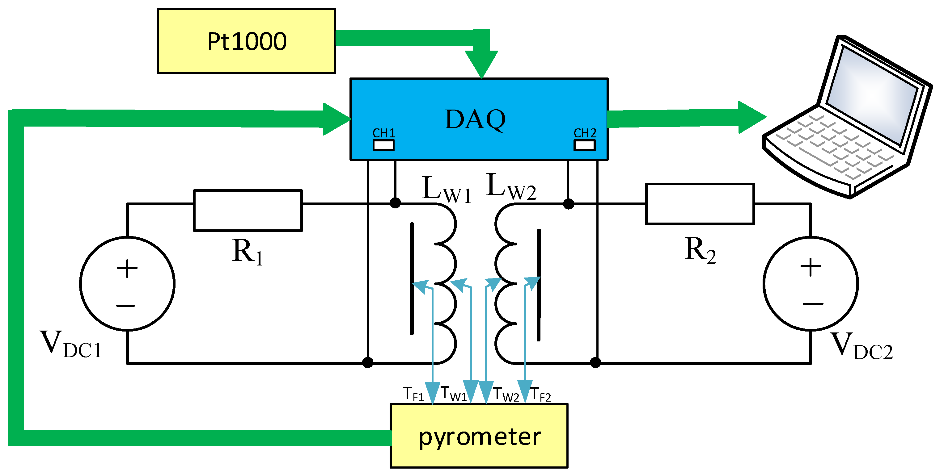
In order to show the correctness and practical usefulness of the presented model, some measurements and calculations were performed. Their results were presented as the dependences of the thermal parameters of the tested transformers on selected parameters characterizing different operating conditions. The measurements were performed using the measurement set-up presented in
Section 3, whereas the calculations were made using the thermal model described in
Section 2. In these calculations, the output current of sources P
W1 and P
W2 are described by the waveforms of the power dissipated in the primary and secondary windings, respectively. After performing a transient analysis, the obtained waveforms of voltages in nodes T
W1, T
W2, T
F1, and T
F2 correspond to temperatures of all the components of the tested transformers. The waveforms of the presented transient thermal impedances and transfer thermal impedances are calculated by dividing the proper excess of temperature of the selected transformer’s components over the ambient temperature through the dissipated power according to the definitions given, e.g., in [
23]. In all the figures shown in this section, the lines denote the calculations results obtained using the presented model, whereas the results of measurements are marked with points.
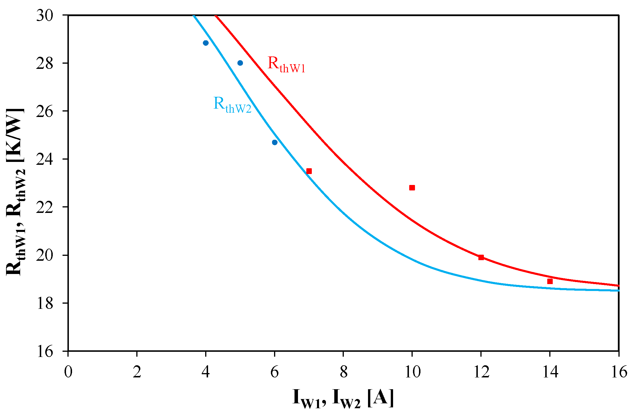
Figure 5 illustrates the dependence of thermal resistances of windings R
thW1 and R
thW2 on the currents flowing through these windings. The presented results correspond to the distances between the windings equal to d
y = 0.8 mm and d
x = 0.
As is visible, the calculations and measurement results are consistent. It is worth noting that dependences R
thW1(I
W1) and R
thW2(I
W2) are monotonically decreasing functions. Such a shape of these dependences is a result of improving the efficiency of heat convection when the temperature of the cooled device increases. This trend is the same as observed in power semiconductor devices [
42]. At the same values of current the value of R
thW1 is higher than R
thW2. In the considered range of changes in current values the considered thermal resistances change even by 25%.
Figure 6 illustrates the influence of the distance d
x between the coils on transfer thermal resistance R
thW1W2 between these coils.
It is easy to observe that the dependence RthW1W2(dx) can be approximated using a linearly decreasing function with satisfied accuracy. In the considered range of change in the values of a distance dx, transfer thermal resistance RthW1W2 decreases up to 20%. It is worth noting that the values of RthW1W2 are even by 50% lower than the values of RthW1.
Figure 7 presents the dependence of R
thW1W2 on the distance d
y between the coils. This dependence was obtained at current I
T = 14.5 A.
It is visible that the dependence RthW1W2(dy) is described by an exponentially decreasing function. An increase in the value of dy from 0 to 18 mm causes even fourfold decrease in RthW1W2.
The results presented in
Figure 5,
Figure 6 and
Figure 7 prove that the equations proposed in
Section 2 describe the measurement results with good accuracy. The mentioned dependences describe thermal properties of an air transformer at the steady state only.
Table 2 presents the values of parameters describing thermal time constants occurring in the compact thermal model of transformer A.
As is visible, the waveform ZthW1(t) is described by three thermal time constants of the values of the range from 1 ms to over 280 s. In contrast, the waveform ZthW1W2(t) is described using only one thermal time constant of the value 488.2 s. Such values of thermal time constants denote that a thermally steady state can be observed about 2500 s after switching on the power dissipated in the tested transformer.
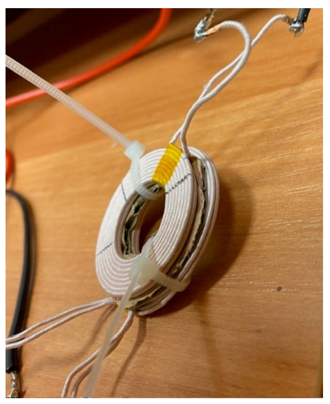
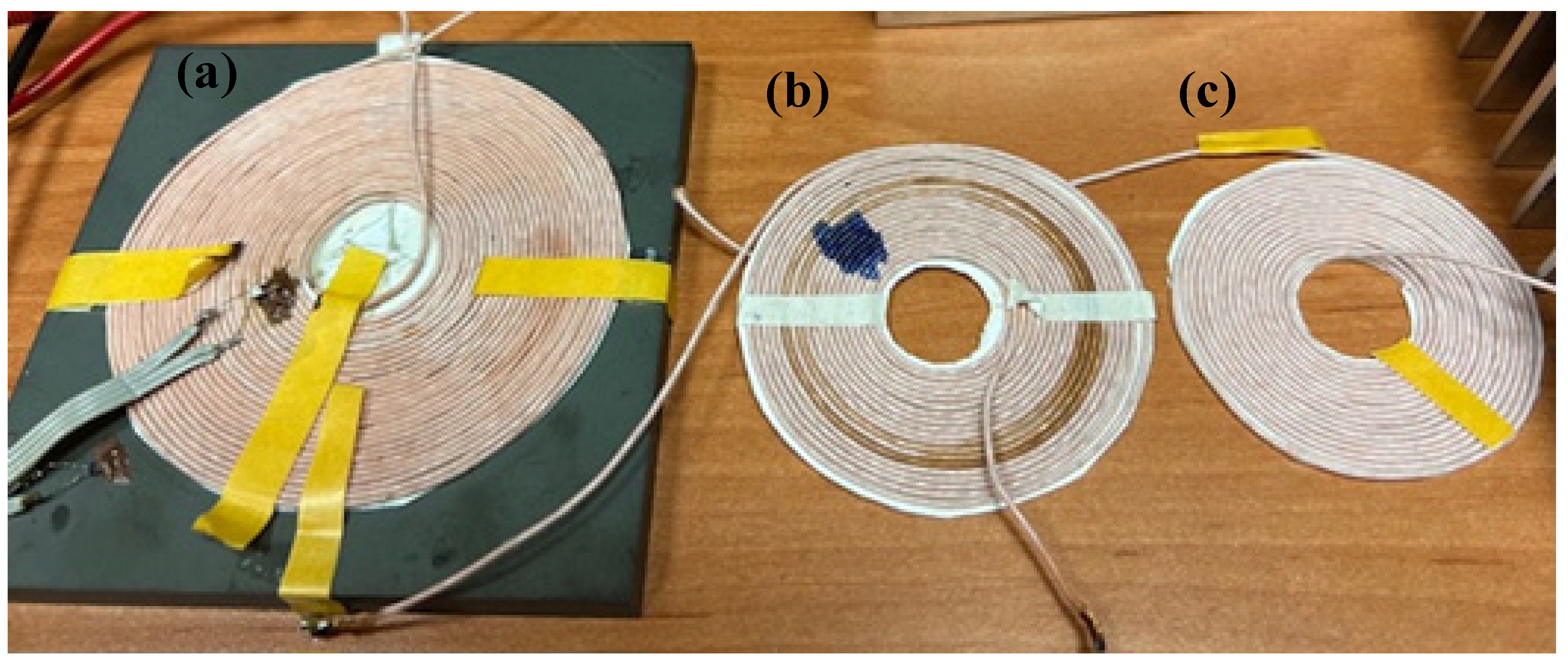
The next group of measurements was carried out for type B transformers containing two identical windings. The results of measurements of thermal parameters of an air transformer with the windings placed on ferrite plates are presented in the further part of this section.
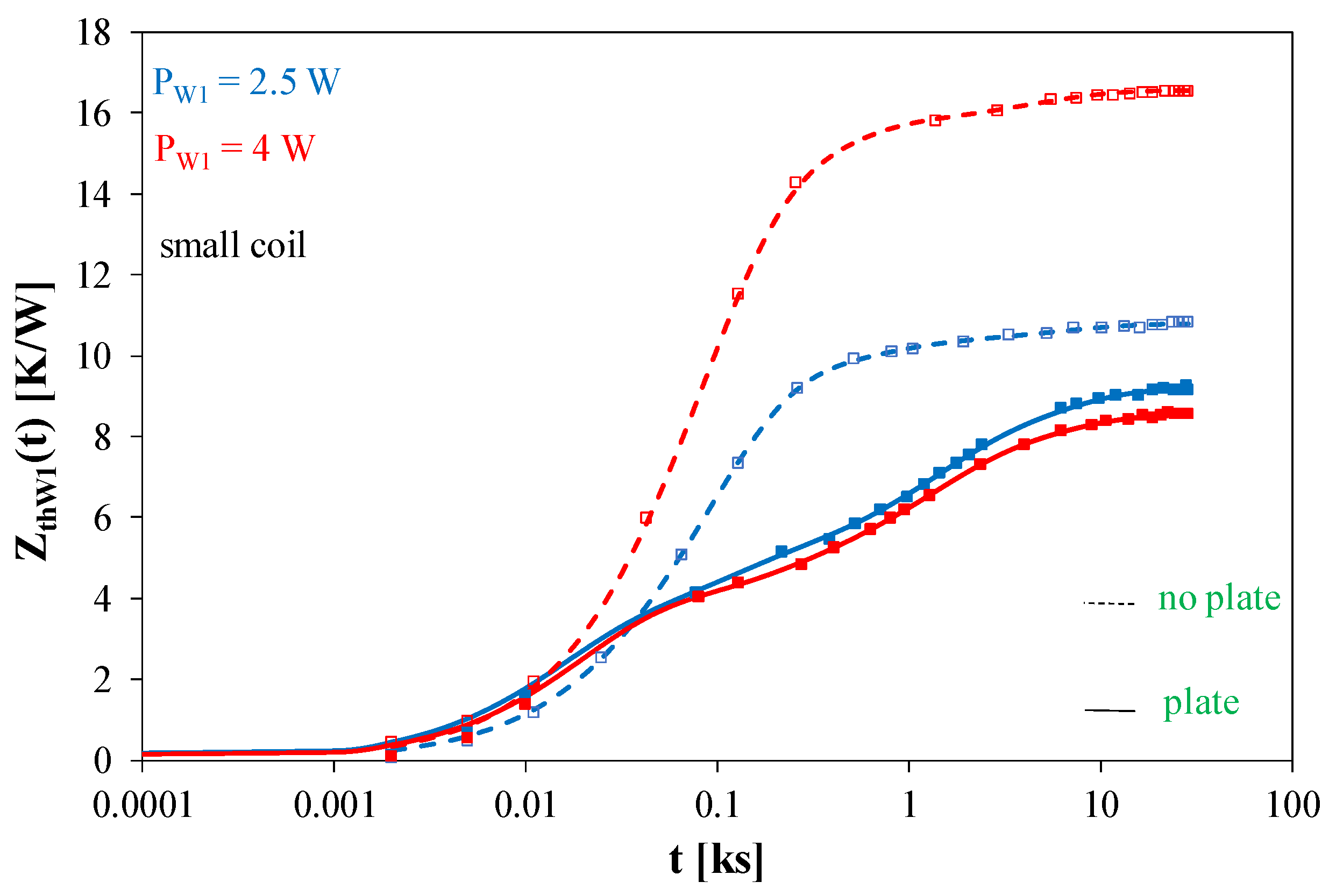
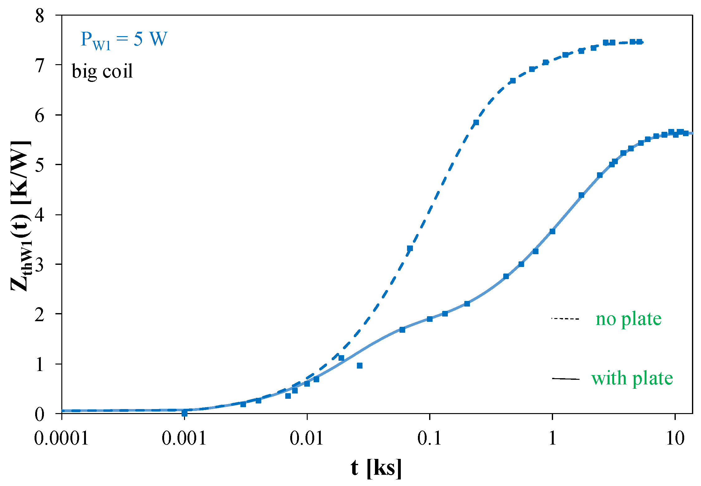
Figure 8 and
Figure 9 illustrate the effect of using a ferrite plate on transient thermal impedance waveforms of an air-core transformer with small coils (
Figure 8) and big coils (
Figure 9) at selected values of the power dissipated in it.
Figure 8 shows that the use of a ferrite plate causes a decrease in the value of Z
thW1(t) at the steady state. The change in this value is bigger for the higher of the considered values of the dissipated power and reaches as much as 50%. It is also worth noting that for the transformer without a ferrite plate, the thermal steady state is achieved much earlier. It is visible already for t > 2000 s, and for the transformer with a ferrite plate—for t > 20,000 s.
As can be seen in
Figure 9, for times t < 20 s the waveforms obtained for both the transformer designs are practically identical, while for longer times there is a clear delay in the waveform obtained for the transformer with a ferrite plate. For this transformer, the steady state was obtained after almost 10,000 s, and for the transformer without a plate after about 1000 s. In the steady state, the values of Z
thW1(t) for the transformer without a ferrite plate were even 40% higher than for the transformer without such a plate.
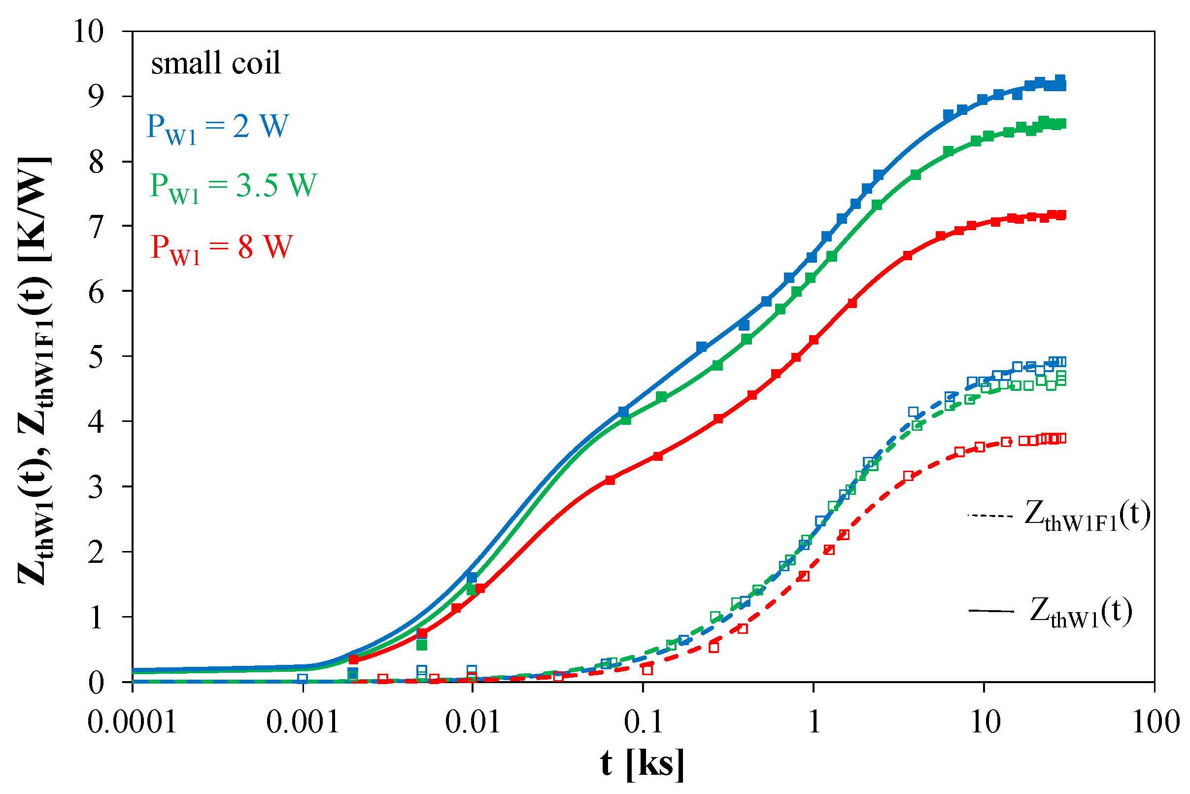
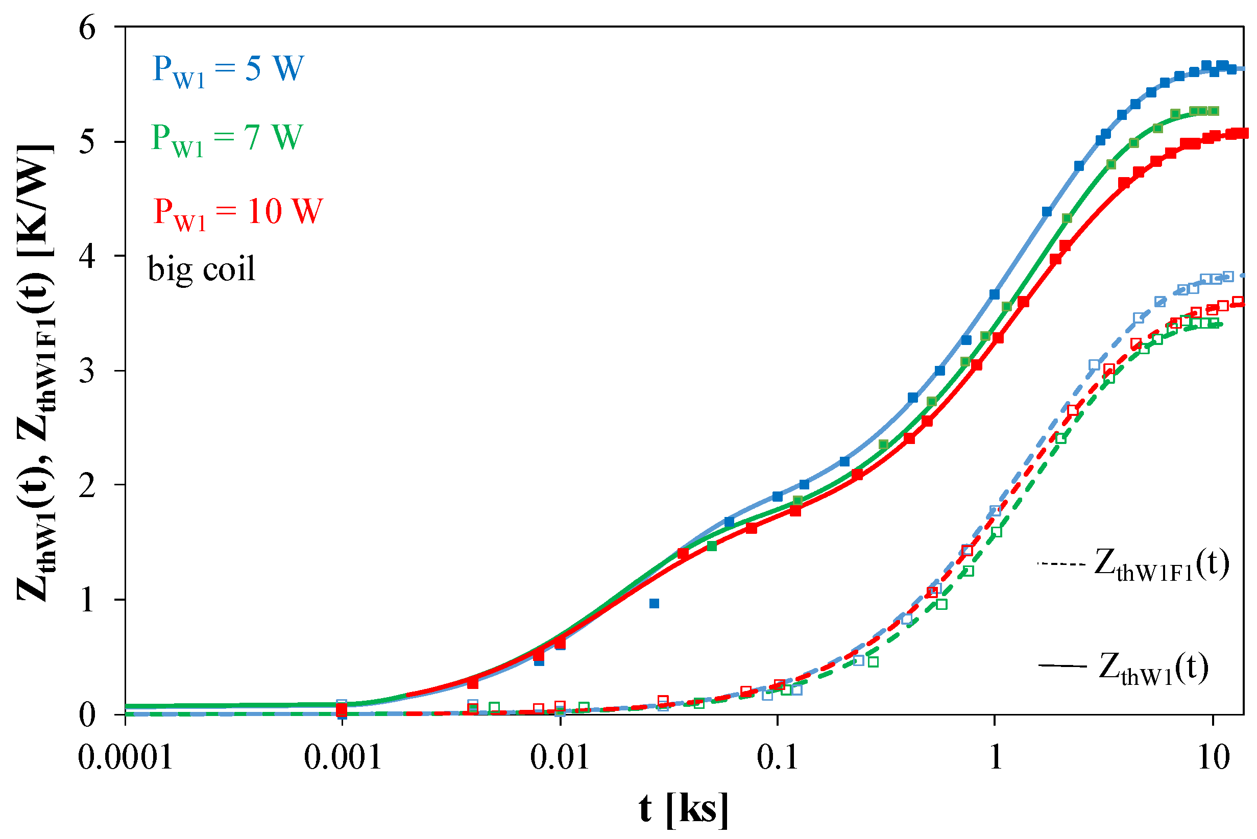
Figure 10,
Figure 11 and
Figure 12 illustrate the influence of the power dissipated in a transformer with a ferrite plate on transient thermal impedance Z
thW1(t) and transfer transient thermal impedance Z
thW1F1(t) waveforms.
Figure 10 presents a transformer with small coils,
Figure 11 a transformer with medium coils, and
Figure 12 a transformer with big coils.
As can be seen in
Figure 10, an increase in the value of the dissipated power improves the cooling efficiency of the tested transformer. This is manifested by a decrease in the value of both transient thermal impedance Z
thW1(t) and transfer transient thermal impedance Z
thW1F1(t). The measured values of Z
thW1F1(t) are almost twice as low as the value of Z
thW1(t). It is also worth noticing that the temperature of the ferrite plate starts increasing about 20 s after the start of heating the coil.
In the case of the Z
thW1(t) waveforms shown in
Figure 11, it can be seen that an increase in the value of the power dissipated in the winding causes a decrease in the value of the measured parameter by up to 15%. In turn, in the case of Z
thW1F1(t) measurements, it can be observed that the waveform Z
thW1F1(t) changes slightly with power changes. It is worth noting that the waveform Z
thW1F1(t) is significantly delayed in relation to the waveform Z
thW1(t).
As can be observed in
Figure 12, the values of Z
thW1F1(t) are 30% lower than the values of Z
thW1F1(t). The delay of the waveform Z
thW1F1(t) in relation to Z
thW1F1(t) is about 20 s. Under the influence of changes in the power value, the values of each of the parameters considered changed by up to 15%.
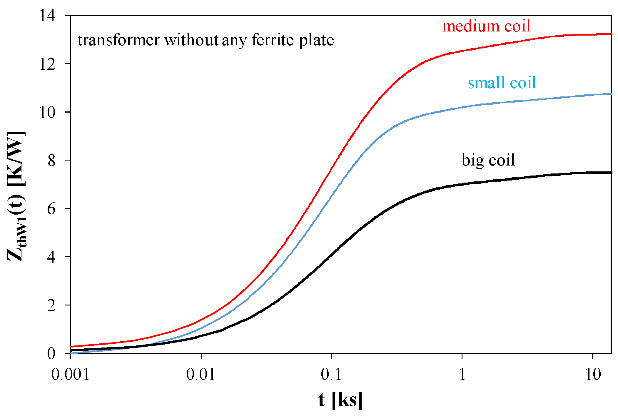
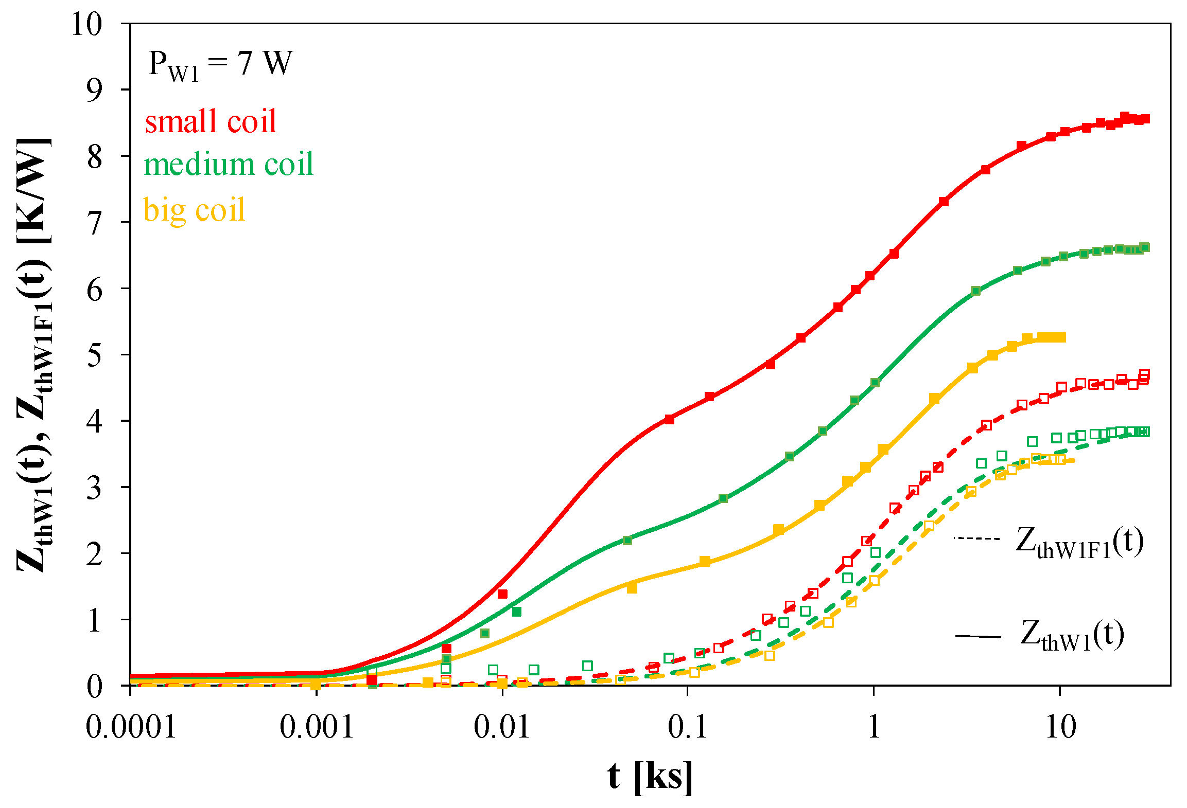
Figure 13 and
Figure 14 compare the transient thermal impedance waveforms of a transformer without a ferrite plate (
Figure 13) and with a ferrite plate (
Figure 14) containing the windings of different sizes.
As can be seen in
Figure 13, with an increase in the size of the windings, lower values of transient thermal impedance are obtained. Between the biggest and the smallest windings, the values of this parameter differ by as much as 35%. There is practically no visible influence of the coil size on the settling time of the considered waveforms.
It is shown in
Figure 14 that at the same value of the dissipated power, the best efficiency of heat removal is observed for the transformer containing the big coil. The value of Z
thW1(t) of this transformer obtained at the steady state is 40% lower than for the transformer containing small coils. The necessary time to obtain the steady state is the highest for the transformer with small coils. The waveforms of Z
thW1F1(t) are smaller than Z
thW1(t). For the transformer with small coils, the considered waveforms differ twice. For the transformer with big coils, such a difference does not exceed 40%.
Analyzing the measurement results presented above, it can be seen that the thermal resistance of the windings for both the transformers is a decreasing function of the coil size, while for the transformer with a ferrite plate, significantly lower (even by 35%) thermal resistance values were obtained. In turn, the transfer thermal resistance between the winding and the ferrite plate for each of the transformers under consideration changes slightly (only by 10%) and is even twice as small as the transfer thermal resistance between the winding and the ferrite plate. The biggest difference between the thermal resistance of the winding and the transfer thermal resistance between the winding and the ferrite plate occurs for small coils and the smallest for big coils.
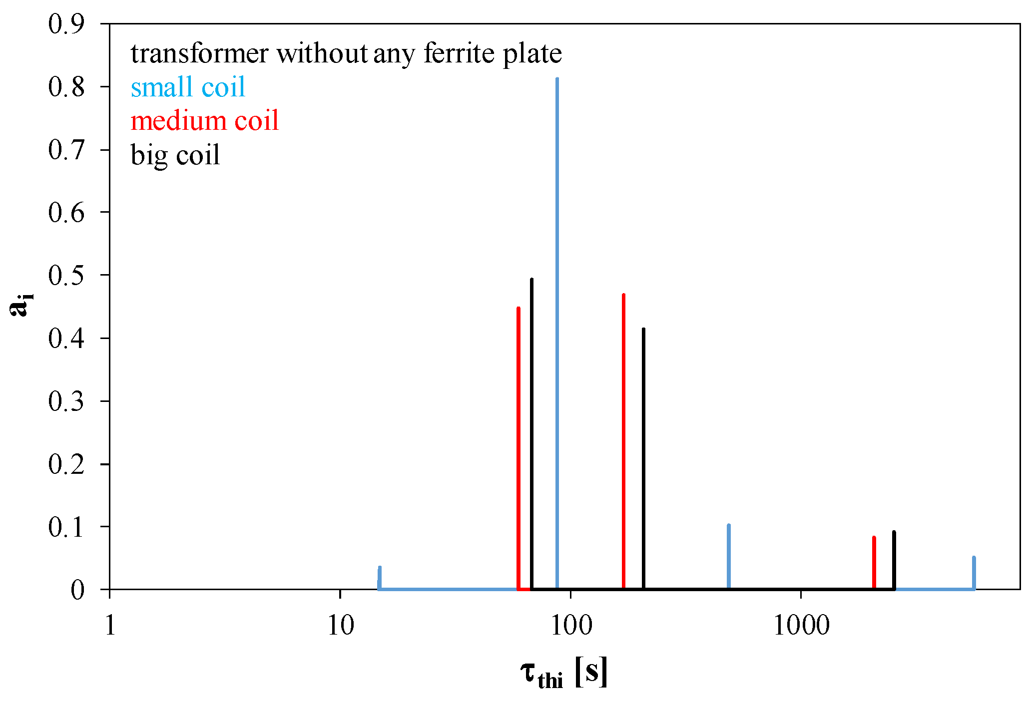
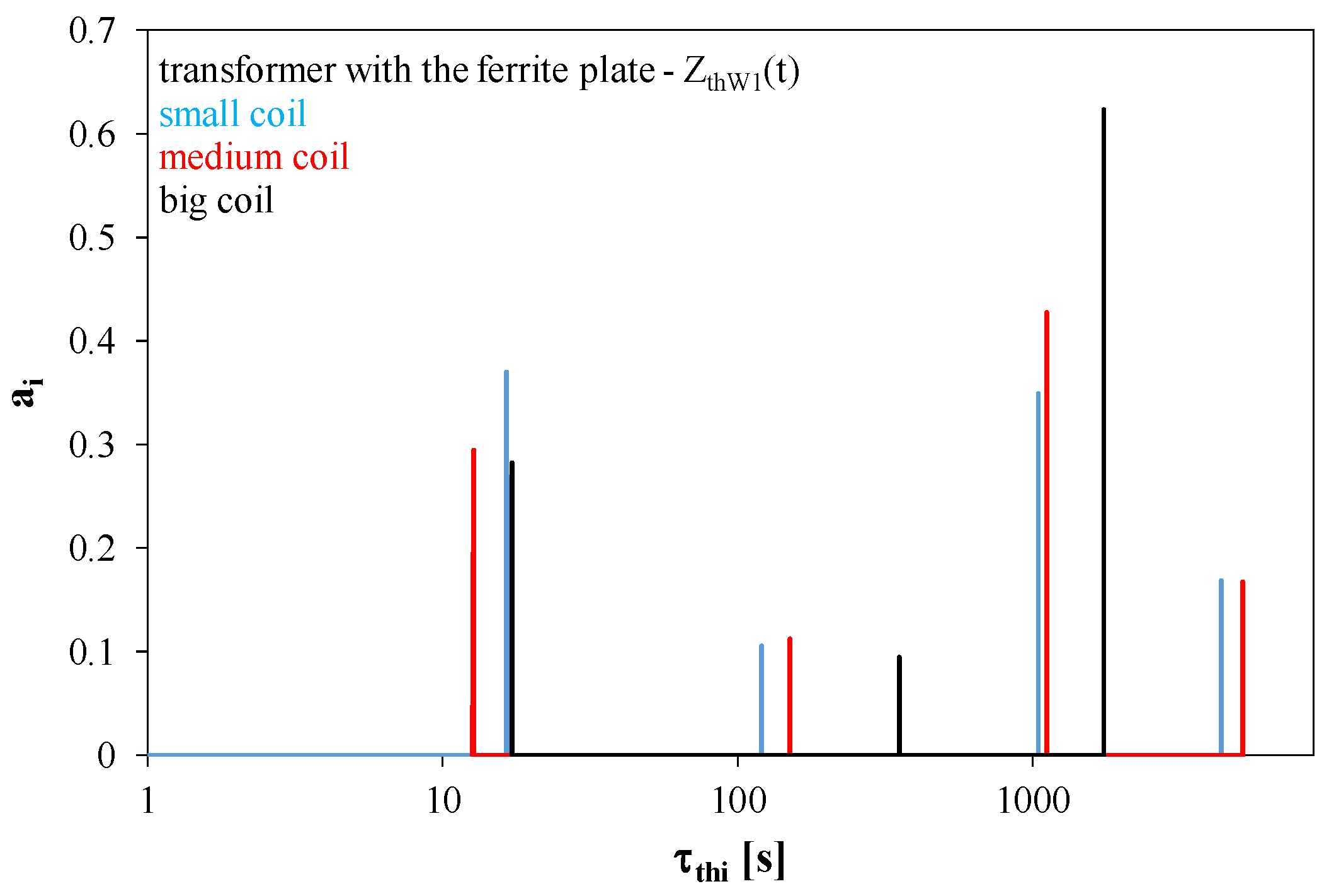
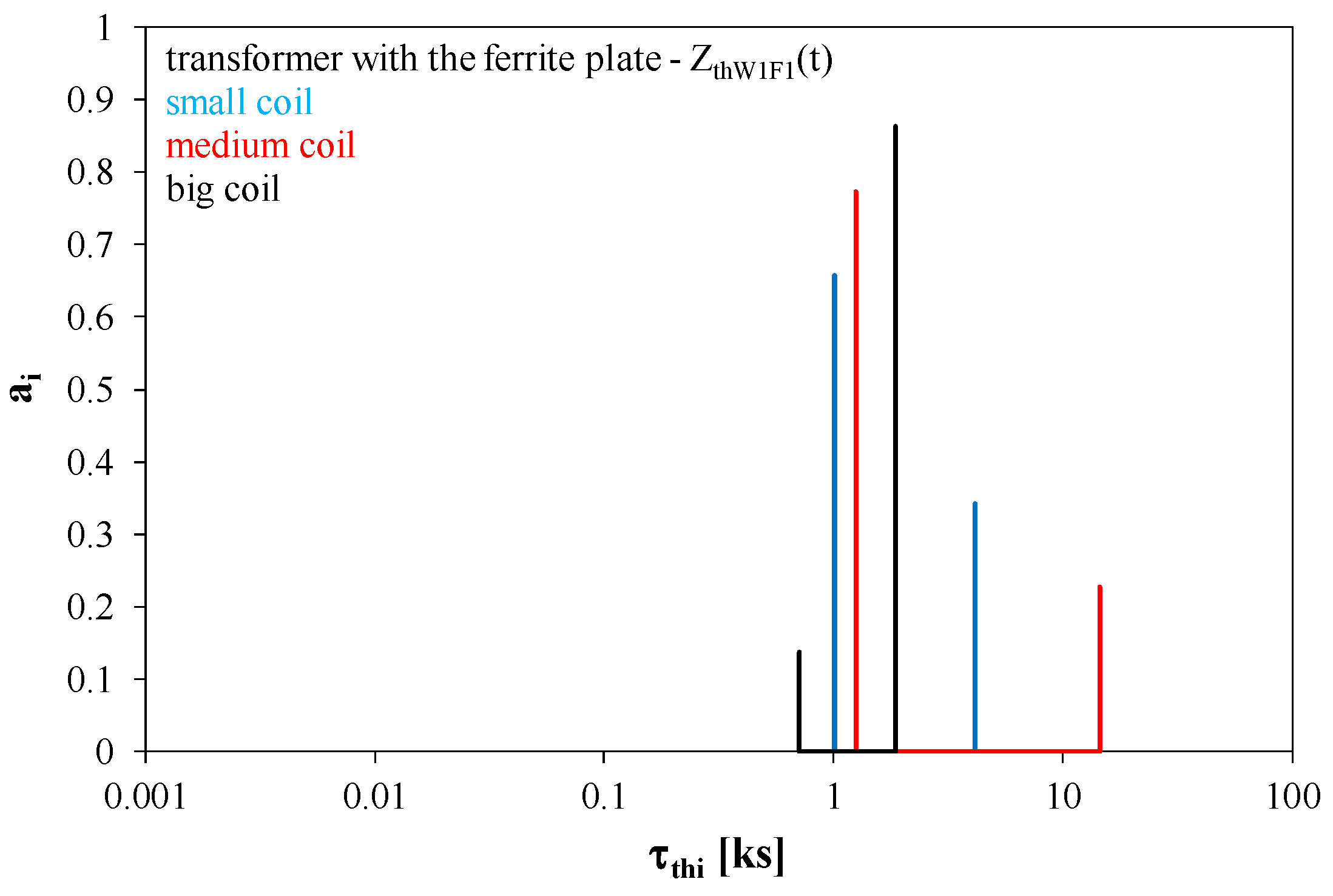
Figure 15,
Figure 16 and
Figure 17 show the spectra of thermal time constants determined for the considered transformers operating without a ferrite plate (
Figure 15) and with this plate (
Figure 16 and
Figure 17). In these figures, red lines correspond to the transformer with small coils, blue lines to the transformer with medium coils, and black lines to the transformer with big coils.
As can be seen in
Figure 15, for the transformers operating without a ferrite plate, there are three to four thermal time constants in the spectrum. Their values are in the range from 10 to 5000 s. The dominant thermal time constant has a value in the range from 70 to 200 s.
In
Figure 16, it can be seen that after placing the transformer windings on the ferrite plate, two dominant thermal time constants are visible with the values close to 10 s and 1000 s. The thermal time constants with the values close to 1000 s related to the heat capacitance introduced to the cooling system by the ferrite plate are of utmost significance. For transformers with medium and small coils, thermal time constants with values of about 5000 s occur.
It can be seen from
Figure 17 that thermal time constants describing the thermal couplings between the transformer winding and the ferrite plate have the values exceeding 800 s. For each of the tested transformers, the dominant thermal time constant has a value of about 1000 s. The longest thermal time constant of about 15,000 s was determined for the transformer containing medium coils.
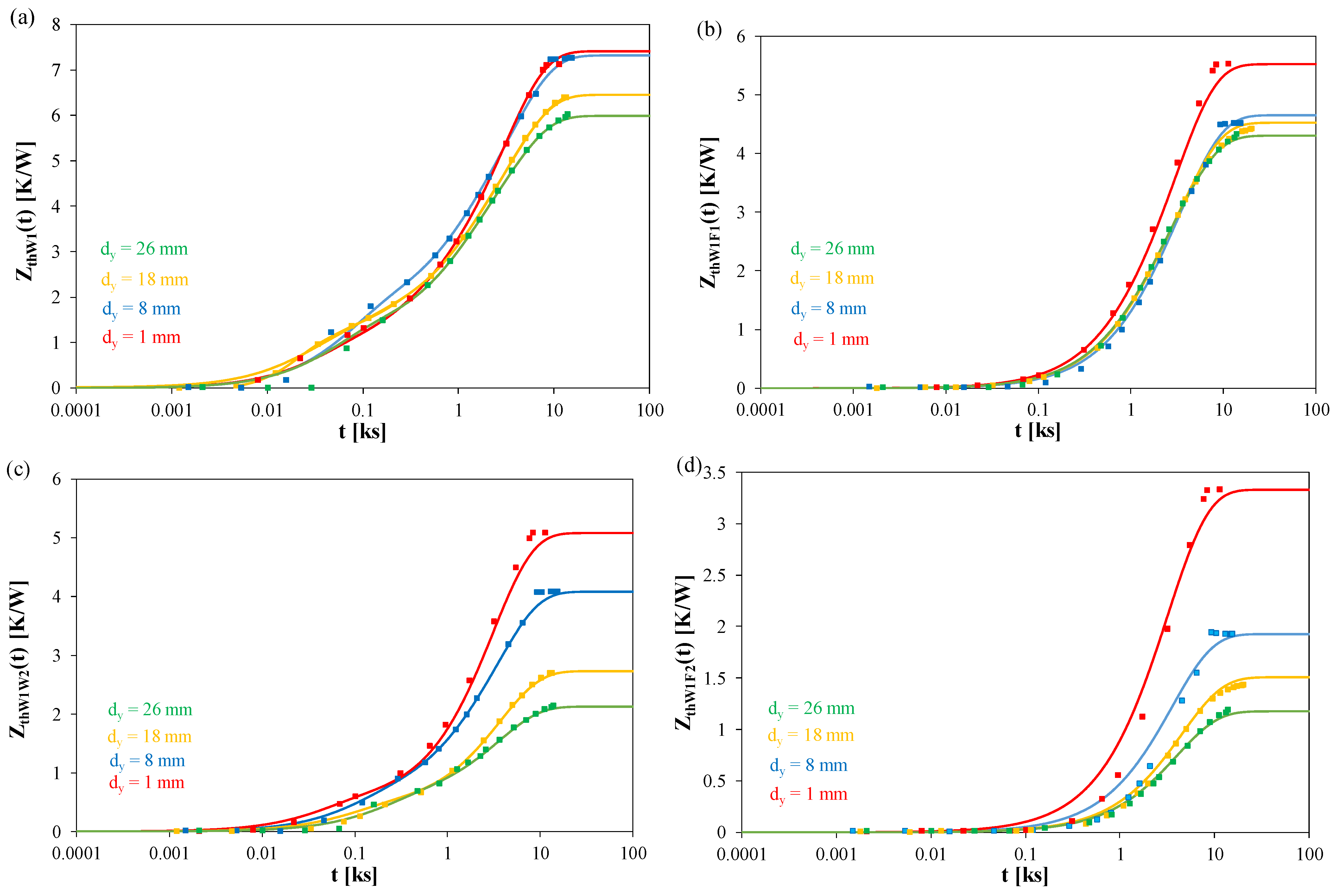
Figure 18 illustrates the influence of the distance d
y between the coils on the courses of self- and transfer transient thermal impedances of the tested transformer. The measurements were made with the power dissipated in the primary winding equal to 8 W. The waveforms of Z
thW1(t) are given in
Figure 18a, the waveforms of Z
thW1F1(t) in
Figure 18b, the waveforms of Z
thW1W2(t) in
Figure 18c, and the waveforms of Z
thW1F2(t) in
Figure 18d.
As can be observed, the change in the distance between the coils only slightly affects the self-transient thermal impedance of the primary winding ZthW1(t) and the transfer transient thermal impedance between this winding and the adjacent ferrite plate ZthW1F1(t). In turn, significant changes, exceeding 50%, are observed for the transfer transient thermal impedances ZthW1W2(t) and ZthW1F2(t). It is visible that an increase in the distance dy causes a decrease in the values of ZthW1W2(t) and ZthW1F2(t).
Figure 19 presents the calculated and measured temperature waveforms of each component of the transformer with big coils obtained during cooling after reaching the steady state with the power dissipation of 8 W in the primary winding. The tests were carried out with a distance between the windings of 1 mm.
As can be seen, at the moment of starting the cooling, the highest temperature was in the primary winding and the ferrite plate to which this winding was glued. The temperature of TW1 exceeded 80 °C, and the temperature of TF1—65 °C. The secondary winding had a temperature only 3 °C lower than the temperature of TF1. The ferrite plate to which the secondary winding was glued was the coldest. Its temperature only slightly exceeded 42 °C. The cooling process started the fastest, after just a few seconds, for both the windings. The ferrite plates began to cool down after about 100 s after the winding power supply was turned off. It took as much as 3 h to fully cool all the transformer’s components to the ambient temperature. It can be seen that the temperature of none of the components exceeds the dangerous value for the tested device. It is worth adding that the results of the calculations and measurements differ very little, which proves the practical usefulness of the presented model.


