1. Introduction
Many industries use various types of steel components to solve countless engineering problems. Some of the most common mechanical elements are gears and toothed gears. There is a great variety of shapes and sizes of such components on the market, which are part of the complex structures of motor vehicles. To meet the high-quality requirements for this type of steel component and ensure appropriate surface hardness during the hardening process, new materials are constantly being explored, and experiments are conducted to optimize the parameters of the heating process. The material parameters of alloy steels from which, for example, gear wheels are made are mainly responsible for the nature of the mechanical element’s operation, its rotational speed, the power transmitted by the element, the working environment, e.g., corrosion, the element’s strength, the working temperature and the method of lubrication [
1,
2,
3,
4,
5,
6,
7].
A well-conducted heating or induction hardening process with full control over its course, i.e., with properly selected processing parameters—such as exposure time, frequency, and effective inductor current—allows the desired mechanical properties of the steel components to be obtained [
1,
2,
7,
8,
9,
10]. As seen from the above information, surface induction hardening, which takes place after rough- and shape-processing of the charge, is a complex issue as it combines electromagnetic, thermal, and metallurgical phenomena.
With the continuous development of many branches of industry using steel elements, the need to ensure the proper course of the hardening process and the development of the market for new semiconductors have resulted in a significant increase in interest in resonant inverters, both single- (MF—medium frequency or HF—high frequency) and dual-frequency (2F) in recent years. Dual-frequency converters are implemented in many possible configurations described in more detail in other works [
1,
2,
4,
11,
12,
13,
14,
15,
16,
17] and use new types of semiconductors in their structure. This article presents a generator for simultaneous, dual-frequency heating in a full bridge structure, abbreviated in the literature as SDF. A converter of this type is characterized by two components of the output current—high frequency (HF) and medium frequency (MF). The HF should be 10 to 30 times higher than the MF. A detailed description of the model of this converter can be found later in the article or in the literature [
1,
2,
4,
11,
12,
16,
17,
18].
In the later part of the article, a coupled computer model of a resonant converter with an exciter-load heating system is presented. This model was used to demonstrate the influence of a magnetic field concentrator on the heating process of a charge, such as a gear wheel. As part of the simulation studies, the characteristics of the magnetic field intensity and magnetic induction, energy density and temperature in the charge (made of 42CrMo4 alloy steel) will be determined for several variants of the exciter current frequency and for the heating system, with and without a magnetic concentrator.
2. Theory of Induction Heating of Gears
Induction heating is a process used to join, harden or soften metals or other conductive materials. This process is considered a complex interdisciplinary issue, combining fields of science such as physics, mechanics and electrical engineering. The description, taking into account all the phenomena occurring during the induction heating process, is quite complex and difficult to fully estimate. This process consists of placing the element undergoing thermal treatment (charge) in a heating system (inductor) powered by alternating current, in which eddy currents are induced under the influence of a time-varying magnetic field B of the same frequency. The frequency of the charge eddy currents is equal to the frequency of the exciter current, but their directions are opposite. The flow of eddy currents causes the release of Joule heat, and the distribution of their density in the inductor-load heating system is uneven. This unevenness is related to the occurrence of electromagnetic phenomena characteristic of induction heating, which include the phenomena of skin effect, proximity, displacement and curvature [
1,
2,
3,
4,
5,
6,
13,
15,
16,
17,
18,
19].
As mentioned earlier, the process of induction heating is based on Maxwell’s electromagnetic equations and the phenomenon of eddy currents, which generate heat according to Joule’s law. Maxwell’s equations in differential form have the following form:
where
E—electric field strength (V/m),
B—magnetic induction (T),
H—magnetic field strength (A/m),
J—electric current density (A/m2),
D—electric field strength of displacement (C/m2),
ρ—electric charge density (C/m3).
Under stationary conditions and assuming a sinusoidal electromagnetic field, the derivative term in Ampere’s equation can be neglected and the system is simplified to the following form:
where ω = 2π
f is the pulsation of the electromagnetic field.
Eddy currents induced in the heated element cause heat release according to Joule’s law which takes the following form:
where
Q—density of heat released (W/m3),
J—eddy current density (A/m2),
E*—coupled complex value of electric field strength.
Since
J = σ
E, where σ is the electrical conductivity of the material, the heat loss power can be written as follows:
The process of heating the material can be described by the following thermal conductivity equation:
where
T—temperature (K),
ρ—density of the material (kg/m3),
cP—specific heat of the material (J/kgK),
k—coefficient of thermal conductivity (W/mK),
Q—density of heat power generated by eddy currents (W/m3).
At steady state (∂T/∂t = 0), the equation simplifies to the following form:
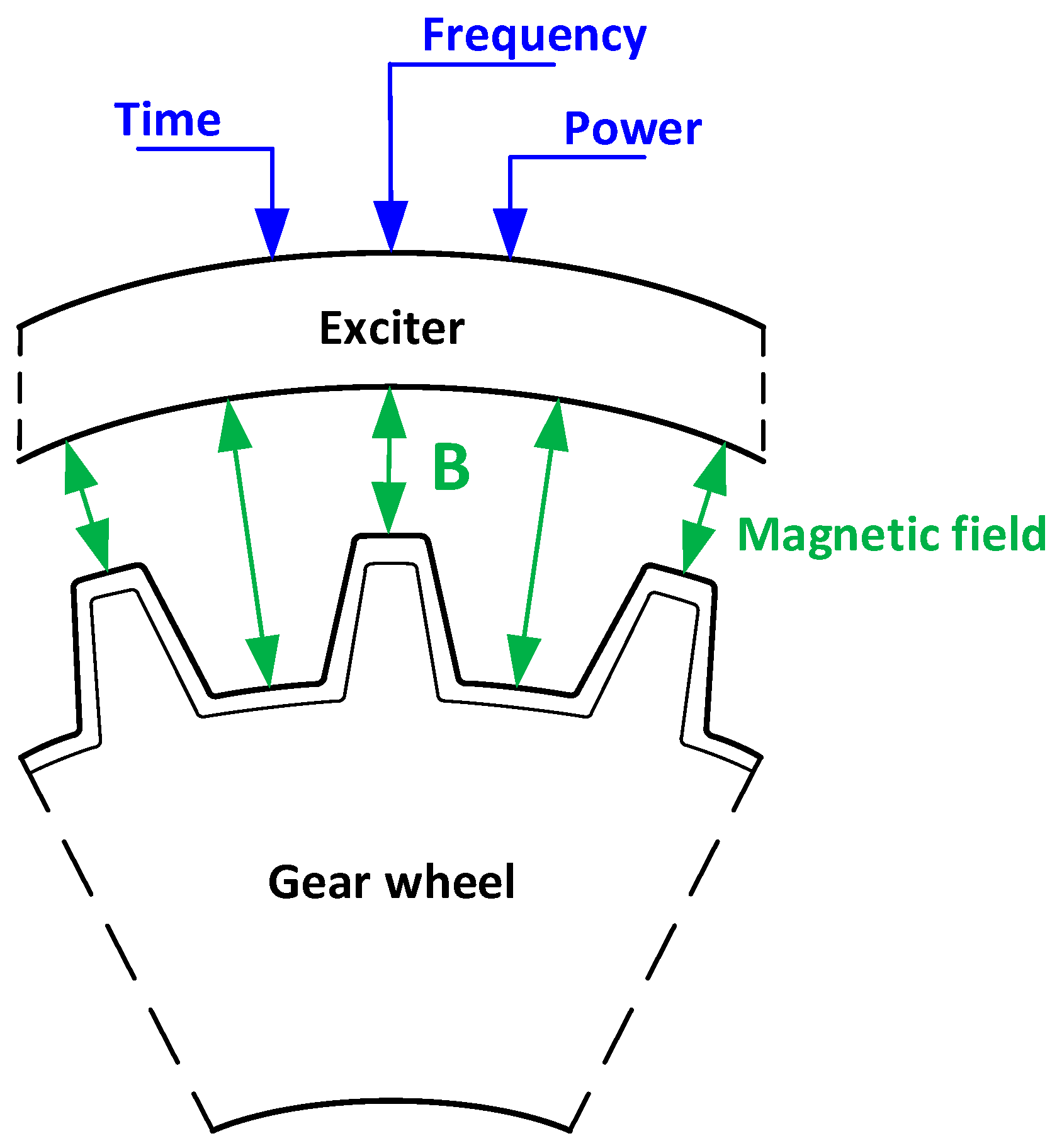
Figure 1 shows an example of the induction heating process. In order to ensure full control over the induction heating process of a load, e.g., in the form of a gear wheel, it is necessary to provide an appropriate value of the power of the inductor-load heating system in a time unit. Additionally, thanks to the appropriately selected frequency of the inductor current, it is possible to control the depth of magnetic field penetration, which directly translates into the distribution of eddy currents in the load [
1,
2,
3,
4,
5,
6,
13,
18,
19].
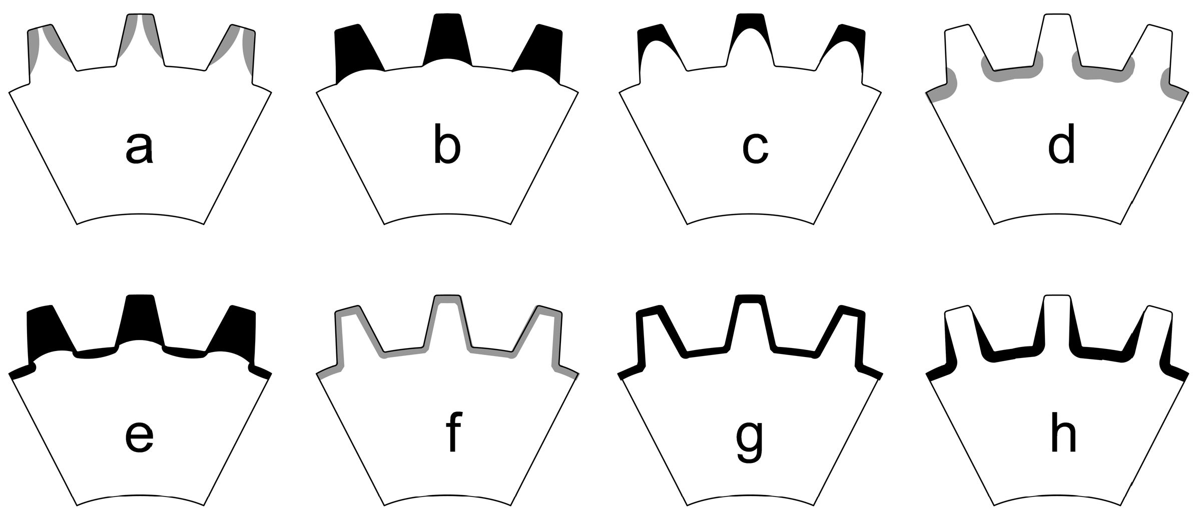
Figure 2 shows the distribution of induced eddy currents in the gear wheel depending on the exciter current frequency. The operation of the inverter system at high frequency (HF) exciter current causes heating of the load surfaces located near the exciter itself (
Figure 2a–c), i.e., the side surfaces of the tooth, teeth, and tooth tips. The medium frequency (MF) of the exciter current heats deeper areas of the load (
Figure 2d,h), mainly the root of the tooth or flank and the root of the tooth. Using dual-frequency (HF + MF) hardening, it is possible to heat the entire tooth and root (
Figure 2e), as well as the contour of the gears (non-uniform pattern—
Figure 2f and uniform pattern—
Figure 2g).
The dual-frequency hardening process can be implemented in different ways since the switching times and power levels of both frequencies can be adjusted. Adjusting these parameters can lead to completely different gear hardness profiles. To harden only tooth tips, high frequencies and high power densities are needed, while the lowest frequencies are used to harden the root of tooth with lower power values [
1,
2,
3,
4,
5,
16,
17,
18,
19]. Thanks to this property, the use of the above hardening method gives satisfactory results, especially the expected hardness profile with relatively small gear deformations (
Figure 2g).
Another way to increase the efficiency of the induction heating process, reduce the heat treatment time and ensure control over the induced magnetic field is to use an additional element in the inductor-charge heating system in the form of a magnetic field concentrator [
1,
2,
3,
4,
5,
13,
16,
17,
18,
19]. Basic information on this type of elements is presented in the next chapter.
3. Basic Information About Magnetic Field Concentrator
Magnetic field concentrators are commonly used in complex induction heating or hardening processes. Using a concentrator in the inductor-charge heating system significantly increases the efficiency of the heating process by controlling the magnetic field and reducing the duration of heat treatment [
1,
2,
3,
4,
5,
18]. The magnetic field is controlled by focusing the magnetic field lines induced by the current flow through the exciter on the most important areas of the elements of the charge. Concentrating magnetic field lines in a small area (instead of widely dispersing them in the air) increases the intensity of this field in close proximity to the material being processed [
1,
2,
3,
4,
5,
10,
11,
12,
13,
14,
15,
16,
17,
18]. Moreover, thanks to the use of a field concentrator from the same coil, more heating power is transferred (the heating force increases) to the selected area of the workpiece, as a result of which, we obtain process optimization consisting of reduced energy consumption (lower heating force in unnecessary areas—losses) and increased speed of the heating process. In summary, concentrating the heating process in a narrowed area improves the quality of production and the efficiency of the process for the processed element. Due to the magnetic properties of the concentrators, energy consumption is reduced, which results in less environmental impact.
Magnetic field concentrators (
Figure 3) are made of magnetically soft materials, including alloys (iron–nickel, thermocompensating, iron–cobalt, iron–silicon) [
2,
3,
4,
18,
20,
21]. In addition, soft magnetic materials consist of powdered magnetic materials and dielectric binders, compressed under high pressure and subjected to heat treatment. Basically, concentrators are used to shape the magnetic flux (concentrate, screen, modify) in such a way that the alternating magnetic field is directed to the desired surface of the workpiece (or part thereof) with a small scattering flux. Soft magnetic materials are characterized by low electrical conductivity, high permeability and low magnetic losses.
Currently, there are several leading manufacturers on the market selling soft magnetic materials suitable for manufacturing various shapes of concentrators. Depending on the frequency used in the induction heating process, three types of materials are used to concentrate the field (
Table 1). There are also ready-made concentrator solutions available in the form of composite, amorphous materials based on cobalt, which, thanks to their plasticity, can be easily formed into the appropriate shape. The parameters of amorphous materials are listed in
Table 2.
After being formed on the coil surface, these materials are cured by heating in an oven at 120 °C for one hour and then increasing the temperature to 190 °C for an additional hour [
21]. After heating, the coil with the hardened material is ready for use in the heater. In addition, amorphous materials used for field concentrators can be further processed after heating to obtain the desired shape.
As can be seen from the data presented in
Table 1 and
Table 2, both solid and amorphous materials were used to concentrate the magnetic field generated by the inductor cover the entire range of frequencies commonly used in induction heating of steel elements. A well-conducted induction heating process [
1,
2,
3,
4,
5,
6,
10,
11,
12,
13,
14,
18,
19] with full control over its course, i.e., with properly selected processing parameters, such as exposure time, frequency and an effective value for the inductor current, allows the desired mechanical properties of the steel elements to be obtained.
In a later part of the article, a coupled computer model of a resonant converter with an exciter-load heating system is presented. This model was used to represent the influence of a magnetic field concentrator on the heating process of a load in the form of, for example, a gear wheel. As part of the simulation studies, the characteristics of the magnetic field intensity and magnetic induction, energy density and temperature in the load (made of 42CrMo4 alloy steel) will be determined for two types of induction heating (with and without a concentrator) and a constant operating frequency of 350 kHz.
4. Coupled Simulation of the Resonant Converter Model
In order to illustrate the influence of the magnetic field concentrator on the induction heating process of the charge, e.g., in the form of a gear wheel, a computer model of the inductor-charge heating system was created, which was coupled with the circuit model of the resonant converter. The circuit model of the high-frequency power electronics converter is shown in
Figure 4 and
Figure 5. The three-dimensional (3D) model of the inductor-load heating system is shown in
Figure 6 and
Figure 7. Coupled simulation (co-simulation) of the full model was performed in ANSYS 2022 R2 software (Twin Builder + Maxwell 3D and 2D).
The coupled computer simulation of the full model of the converter connected to the heating system was performed for the following operating conditions:
The inverter was powered from a three-phase network with a phase-to-phase voltage of 400 V (RMS).
The output power of the inverter was 3.5 kW.
The MOSFET transistors used in the model were modeled in accordance with the catalog date [
22] of transistors marked GCMS040A120S1.
The values of inductance
L3 and resistance
R3 were determined in the laboratory using a precise impedance analyzer [
23] and correspond to the parasitic parameters of the copper inductor with the dimensions shown in
Figure 6.
The magnetic field concentrator, whose parameters are listed in
Table 1 and dimensions are shown in
Figure 7, is made entirely of Fluxtrol 50 material.
A load in the form of a gear wheel with the fallowing dimensions: diameter 46 mm, number of tooth 21, tooth height 4.2 mm is shown in
Figure 6.
The load in the form of a gear wheel from
Figure 7 is made entirely of 42CrMo4 alloy steel, the parameters of which are listed in
Table 3. Additionally, in
Table 4, the percentage chemical composition of the 42CrMo4 steel is summarized [
9,
20].
Two types of induction heating at a high frequency (HF) of 350 kHz were analyzed in the simulation studies under the following conditions:
Using an additional magnetic field concentrator on the exciter,
Without an additional magnetic field concentrator (exciter alone).
Figure 4 shows the circuit model of the power electronics converter, which was used to set the operating frequency of the system and force the exciter current to flow. As can be seen from this figure, the circuit model included a three-phase supply network (3 × 400 V), a six-pulse diode rectifier with an
RC filter (
R1 = 100 mΩ,
C1 = 5 mF), a bridge inverter, a series-parallel resonant circuit with a separating transformer (15:1) and a model of the exciter-charge system. The parameters of the
RC filter used downstream of the diode rectifier were selected experimentally in such a way that, from the inverter side, the system sees a near-perfect DC supply.
The power electronics converter modeled in ANSYS software had a rated power of 3.5 kW and was loaded with a series-parallel resonant circuit with the parameters shown in
Table 5.
The GCMS040A120S1 SiC MOSFET transistors used in the resonant inverter structure in
Figure 4 were modeled according to their datasheet [
22]. According to the manufacturer’s data sheet [
22], these transistors are characterized by a conduction resistance
RDS(on) of 40 mΩ, a maximum drain-source voltage
VDSS of 1200 V and a maximum drain current
IDmax of 40 A. This SiC MOSFET transistor is manufactured in a SOT-227 package whose thermal resistance of junction to case is 0.6 °C/W. Additionally, the internal housing of the SiC transistors also includes fast Schottky diodes, which are also marked on the converter schema in
Figure 4. The main arguments for choosing this type of MOSFET transistors were low power losses, fast internal diodes and very short switching times. The laboratory prototype and research results of this converter are discussed in detail, among others, in [
16,
17,
19].
As mentioned earlier, the circuit model of the converter in
Figure 4 and
Figure 5 was coupled with the FEM model of the inductor-charge heating system, which is shown in
Figure 6 and
Figure 7. The purpose of combining these two models was to force a current of 350 kHz from the resonant circuit of the inverter through a copper exciter. This procedure is necessary to perform a complex FEM analysis of the exciter-load heating system in ANSYS Maxwell software. The material parameters of the FEM model from
Figure 6 and
Figure 7 were taken from ANSYS libraries and from the literature [
8,
9,
10,
18,
20,
21]. In order to obtain satisfactory calculation accuracy and a decent simulation time, it was decided to densify the calculation mesh on the most important elements of the heating system—the gear wheel and the magnetic concentrator. The number of mesh elements varied and for the gear wheel, it was 1,750,000 elements, for the concentrator, 2,700,000 elements and for the exciter, 750,000 elements.
The presented computer model was simulated, as mentioned earlier, for a gear wheel load (diameter 46 mm, number of tooth 21, tooth height 4.2 mm) made of 42CrMo4 structural steel alloy (
Table 3) for two operating modes: with and without an additional magnetic field concentrator. For each of the heating system operating modes, an FEM analysis was performed, taking into account the distribution of magnetic induction
B, the distribution of current density
J in the horizontal plane, the distribution of energy density
E in the horizontal and transverse plane of a single tooth, and the distribution of the temperature
T in the horizontal and transverse plane of a single tooth. In each case, the exciter current frequency was the same and was 350 kHz.
In the next chapter of this article, the most important results of the coupled FEM simulation are presented, illustrating the effect of using a magnetic field concentrator on the induction heating process of a gear wheel charge.
5. Results of Coupled FEM Simulation of the Computer Model
Analyzing
Figure 8 and
Figure 9, it can be seen that the use of a magnetic field concentrator made of Fluxtrol 50 material, the material parameters of which are listed in
Table 1, results in an increase in the magnetic induction intensity from about 18.7 mT to about 27.4 mT. The use of an additional magnetic field concentrator in the heating system significantly increases the magnetic induction in the charge, particularly in the notches and at the tooth tips. There is a so-called “enveloping” distribution of magnetic induction on the heated element.
In order to better illustrate this effect,
Figure 10 shows a cross-section (2D) in the transverse plane of the heating system model illustrating the magnetic induction distribution.
Analyzing
Figure 10, it can be seen that the highest value of magnetic induction in the exciter-charge heating system in the case of using a magnetic field concentrator occurs between the exciter and the concentrator. This effect is related to the concentration, accumulation and displacement by the concentrator material of the magnetic field induced by the exciter as a result of the flowing current. The lower part of the heating system not covered by the concentrator is characterized by a natural and theoretically consistent arrangement of magnetic field lines dispersed in the air.
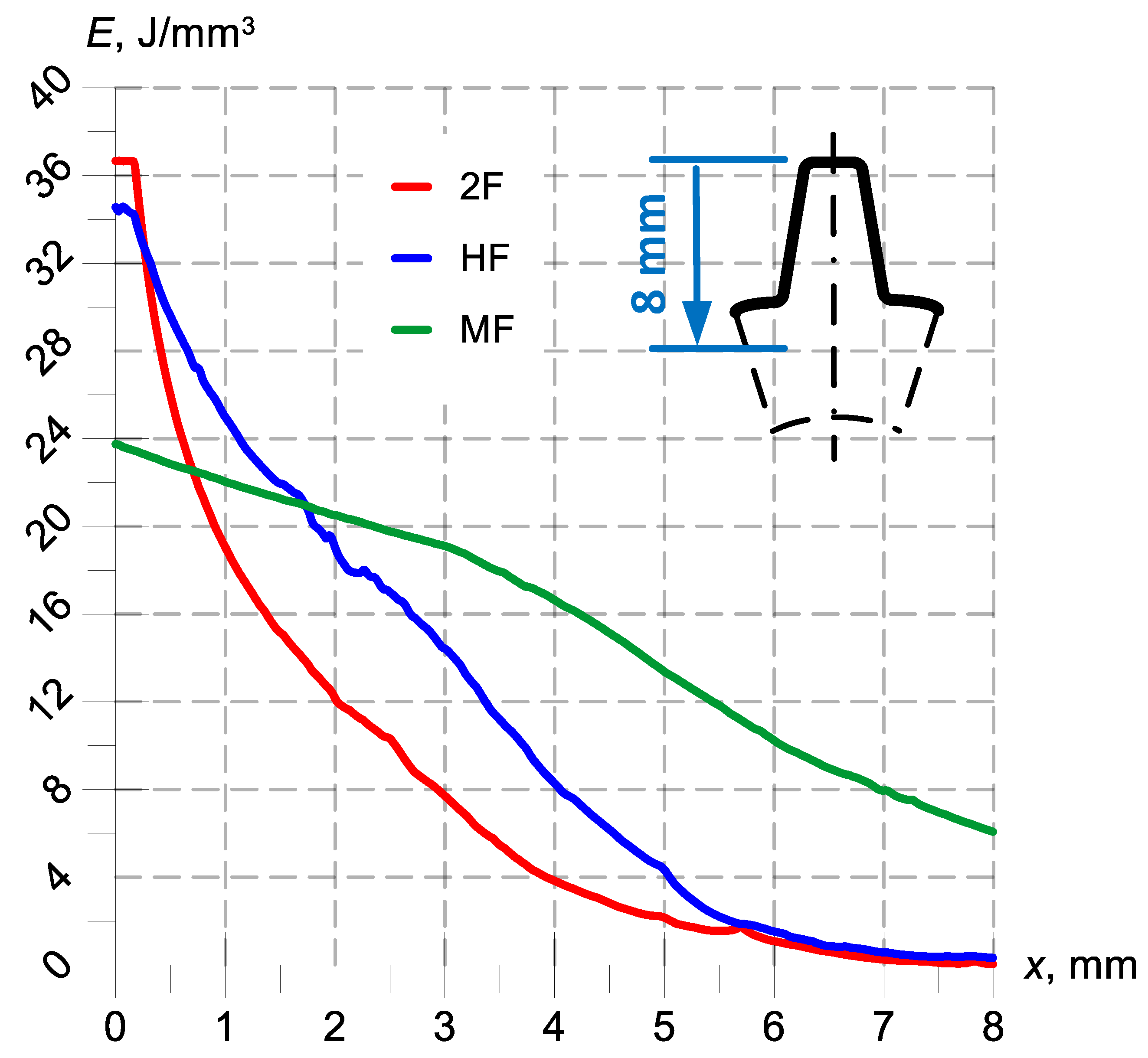
In the next step of the FEM simulation, the energy density characteristics, E (
Figure 11), were determined for the three basic induction heating methods (MF, HF and 2F). These characteristics were determined in the transverse plane of a single tooth as a function of the distance from its tip.
Analyzing
Figure 11, it can be seen that for a heating system consisting only of a copper inductor and a charge, e.g., in the form of a gear wheel, the energy density distribution varies depending on the inductor current frequency—which is consistent with the theory presented at the beginning of this article. In the case of low frequency (MF) charge heating, the maximum value of energy density occurs at the tooth tip and is approximately 24 J/mm
3. With increasing distance towards the gear wheel center, the energy density decreases to approximately 6.5 J/mm
3, which gives an average energy density in this area (8 mm) of approximately 15 J/mm
3. In the case of high frequency (HF) charge heating, we obtain an envelope distribution of energy density with a maximum value (at the tooth tip) of approximately 33 J/mm
3. With increasing distance towards the gear wheel center, the energy density decreases to approximately 1.5 J/mm
3, which gives an average energy density in the entire area under consideration of approximately 17 J/mm
3. In the case of the dual-frequency induction heating method (2F), the envelope contour of energy density is even more visible, as the phenomenon of displacement of eddy currents generated in the charge increases. The maximum energy value in this case is approximately 37 J/mm
3. The energy density distribution characteristic from
Figure 11 for this heating method is an exponential function.
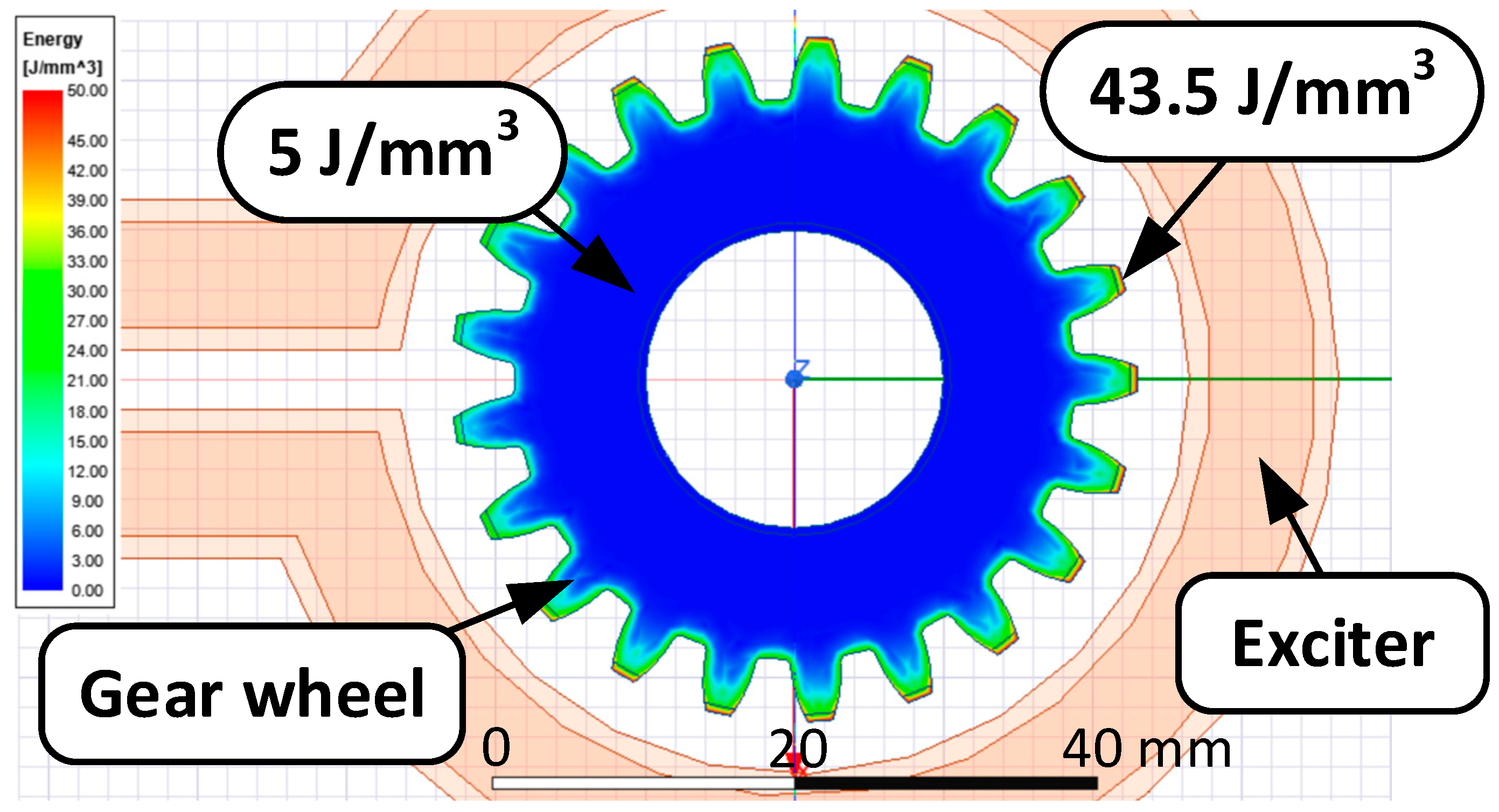
In addition, the influence of the magnetic field concentrator on the energy density is shown in
Figure 12.
Analyzing this figure, it can be seen that the energy density distribution does not differ much from the magnetic induction distribution
B. The highest energy value
E in this case is about 43.5 J/mm
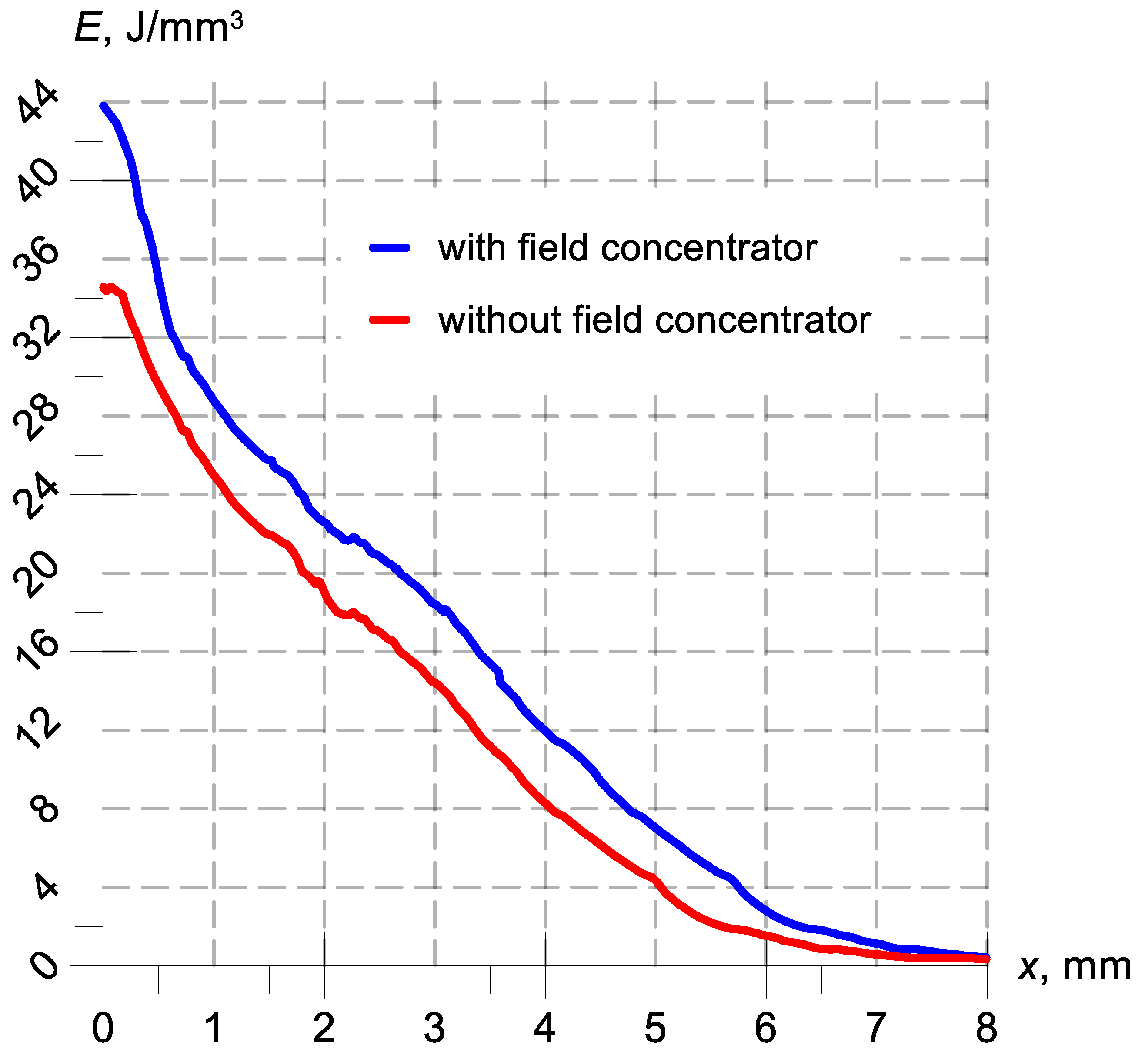
3 and was recorded at the tooth tips. To compare the two operating modes of the heating system (with and without a magnetic field concentrator), it was decided to determine the energy density characteristics as a function of the distance x from the tip of a single tooth and in its horizontal plane. These characteristics are shown in
Figure 13. In order to improve the readability of the energy density characteristics,
Figure 13 shows a comparison only for high-frequency (HF) heating.
Analyzing the energy density characteristics on a single tooth, as shown in
Figure 13, it can be seen that the influence of using a magnetic field concentrator in the heating system is noticeable at a length approx. 7 mm smaller than the radius of the gear wheel (measured from the tooth face). The average energy increase in the area under consideration is approximately 4.3 J/mm
3. A further increase in the length measured from the tooth face (x > 7 mm) results in the disappearance of differences in the use of the concentrator in the heating system—its influence is unnoticeable and the difference n energy density is close to zero. It should be noted that the frequency of the heating system, the type of steel from which the charge (heated element) is made and the type of field concentrator used have a major impact on this state of affairs. In the case of low-frequency charge heating, the influence of the field concentrator will be visible in the entire area under consideration.
Additionally, as part of the work, it was decided to determine the characteristics of the changes in the temperature values reached at the tip of a tooth made of 42CrMo4 steel for two operating modes as a function of the exciter current flow (
Figure 14).
Analyzing the collective data of magnetic induction B, energy density E and temperature T recorded at the tip of a single tooth, it can be seen that using the method of heating the charge with high HF frequency (e.g., 350 kHz) using a magnetic field concentrator, much higher values for these quantities can be achieved. Additionally, by selecting an appropriate structural steel alloy (characterized by, e.g., higher carbon content) of the heated element, the values of these quantities can also be influenced. By using a magnetic field concentrator, it is possible to control the process of magnetic field penetration into the heated element, e.g., one of a rather complex and irregular shape, as well as of any chemical composition. In addition, the use of a field concentrator allows you to speed up the heating process, increase its energy efficiency and reduce the costs of electricity consumption.
The values of magnetic induction B, energy density distribution E and temperature T obtained by means of coupled simulation of the circuit model and the FEM model may result from the following:
From weak coupling between the exciter and the charge (a distance of approx. 4 mm);
Modelling error, because the mathematical model does not accurately reflect reality;
Error in the coefficient values of differential equations—the assumed values of the coefficients of differential equations and boundary conditions, e.g., material data, are burdened with an error;
Rounding error, i.e., an error resulting from multiple approximations of repeated model values.
6. Laboratory Verification of the Operation of a High-Frequency Resonant Inverter for Induction Heating
Figure 15 shows the circuit diagram of the high-frequency inverter. This circuit uses a full-bridge configuration consisting of four power silicon-carbide (SiC) field-effect transistors. The transistors used were GCMS040A120S1 SiC MOSFETs (
T1 ÷
T4) with Schottky barrier diodes (
DS1 ÷
DS4). According to the manufacturer [
22], these transistors are characterized by a conduction resistance
RDS(on) of 40 mΩ, a maximum drain-source voltage
VDSS of 1200 V and a continuous drain current
ID of 40 A. This SiC MOSFET transistor is manufactured in a SOT-227 package whose thermal resistance of junction to case is 0.6 °C/W.
The MOSFET transistors were controlled by a Launch Pad TMS320F28069M system which implemented a PWM algorithm. A detailed description of the implementation of the control system has been previously discussed and can be found in the literature [
16,
17]. Because detailed tests of the presented inverter have been widely described, among others in the literature [
16,
17,
19], where, e.g., the analysis of power losses in SiC MOSFET and possible types of commutation were presented, it was decided to present only the most important measurements for the purposes of this article.
Figure 16 shows waveforms of top-side transistor voltage
vT1 and inverter output current
i flowing through the resonant circuit for a simultaneous, dual-frequency operating mode.
The laboratory tests were conducted under the following conditions:
The SiC MOSFETs were placed on a closed-circuit water-cooled heat sink;
The modulation depth was 0.8 and was set in software in the Launch Pad TMS320F28069M;
Modulating (medium) frequency of the MF was fr1 = 30 kHz;
Carrier (high) frequency of the HF was fr2 = 350 kHz;
The temperature of the MOSFETs transistors was controlled using NTCLE100E3334JB0 thermistors glued directly to the transistor housing with Loctite structural adhesive;
The cooling water temperature was measured directly using a CENTER 521 digital multimeter.
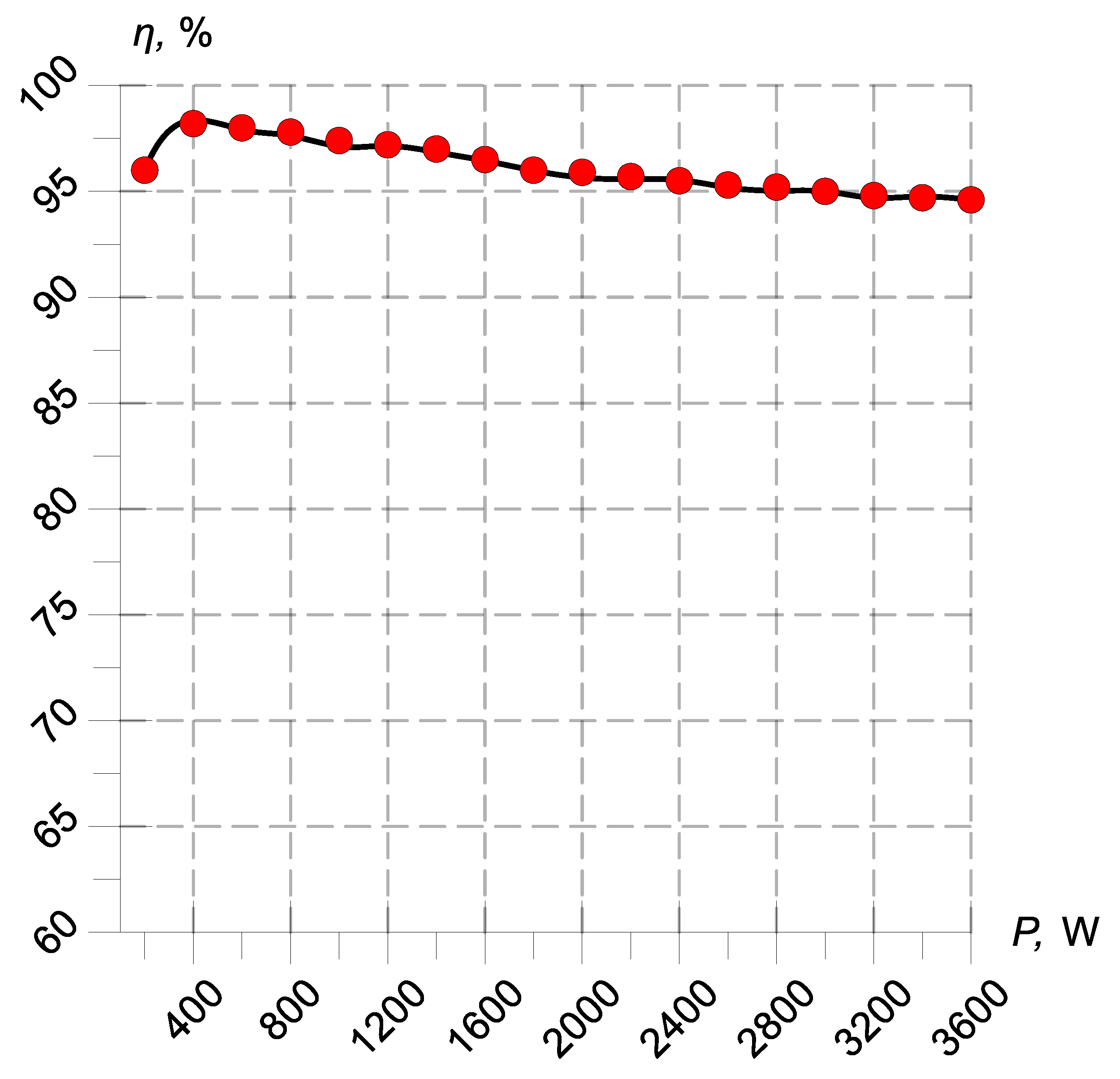
The drain efficiency of the presented inverter, determined using a precise Yokogawa WT-5000-6 power analyzer [
24], was 95.8%.
Figure 17 shows the efficiency characteristics of a high-frequency inverter based on SiC MOSFET transistors.
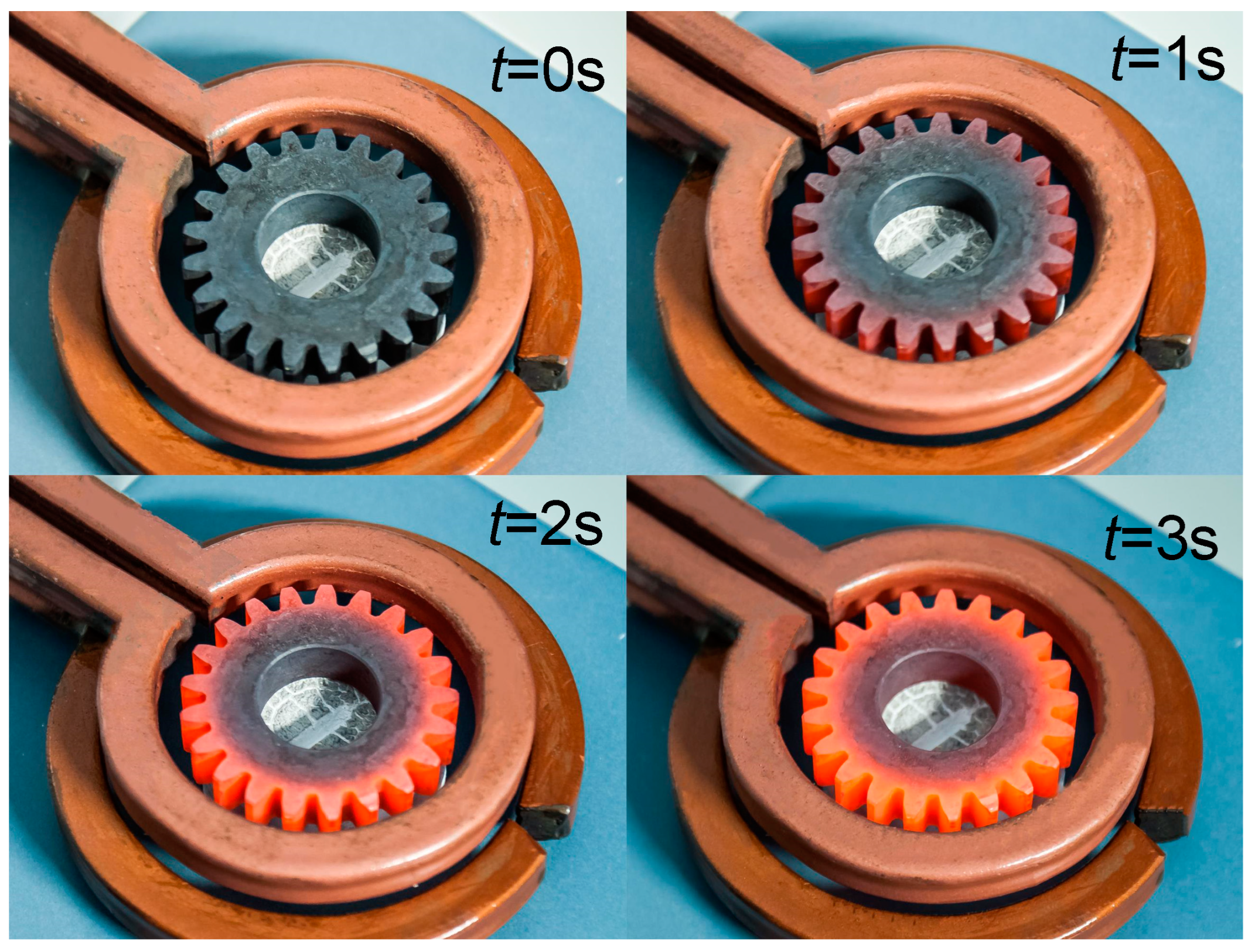
Figure 18 shows the photo of the gear heating process. The dimensions of the heated element are: outer diameter 46 mm, inner diameter 21 mm, height 10 mm, number of tooth 21. The gear is made of 42CrMo4 alloy steel. Co-simulation tests of the heating system are presented in the earlier chapters of this article.
7. Conclusions
The article presents simulation studies of a computer model of a bridge, high-frequency resonant inverter built based on SiC MOSFET transistors. The presented circuit model of the inverter together with the series-parallel resonant circuit was characterized by an operating frequency of 350 kHz, a rated power of 3.5 kW and was coupled with a 3D model of a heating system consisting of an inductor and a charge in the form of a gear wheel with a diameter of 46 mm made of typical 42CrMo4 alloy steel. As a result of the coupled FEM simulation performed in ANSYS 2022 R2 software, the distributions of magnetic induction B and energy density E recorded on the gear wheel were obtained for two types of induction heating—with and without the use of a magnetic field concentrator. Additionally, as a result of co-simulation, the characteristics of changes in the energy density distribution in the transverse plane of a single tooth and changes in temperature at the tooth tip as a function of the current flow intensity were obtained. In addition, the article contains the material parameters of 42CrMo4 alloy steel, which is commonly used for the production of various types of steel elements, as well as basic information about Fluxtrol magnetic field concentrators.
The simulation studies presented in this article were confirmed during experimental studies on a real resonant converter system, supplied from a 3 × 400 V network, which was characterized by an output power of 3.5 kW and an efficiency of about 96%. The results of laboratory measurements, including time courses of the inverter voltages and currents and photos of the gear wheel during the heating process, are included in this article.
The simulation studies presented in this article are a continuation of the research topics undertaken and complement previous laboratory studies, which confirmed the usefulness and possibility of wider application of resonant inverters in induction heating. The use of an additional magnetic field concentrator in the heating process affects the change in the process speed and allows free shaping of the hardness profile of the charge in the form of a gear wheel, depending on the required applications.


