Review

Comprehensive Review of Thermal and Thermohydraulic Performance in Solar Air Heaters with Advanced Artificial Roughness Geometries

Centre for Hydrogen and Renewable Energy, School of Engineering and Technology, Bundaberg Campus, Central Queensland University, Bundaberg, QLD 4670, Australia
*
Author to whom correspondence should be addressed.
Energies 2025, 18(23), 6157; https://doi.org/10.3390/en18236157
Submission received: 8 October 2025 / Revised: 15 November 2025 / Accepted: 20 November 2025 / Published: 24 November 2025

Abstract

This study provides a detailed review of the thermal and thermo-hydraulic performance of solar air heaters (SAHs) enhanced through the application of artificial roughness on the absorber plate. Various roughness geometries, such as wire ribs, V-shaped ribs, arc-shaped ribs, and rib-groove patterns, have been analysed to assess their influence on heat transfer enhancement and frictional behaviour. Findings from previous experimental and numerical studies reveal that the incorporation of artificial roughness can increase the Nusselt number by approximately 1.25 to 6.3 times and improve thermal efficiency by 20–35% when compared to smooth absorber plates. The review further highlights that the most effective performance occurs at a relative roughness height (e/D) between 0.02 and 0.05 and within a Reynolds number range of 10,000 to 18,000. Overall, the analysis confirms that artificial roughness is a simple, economical, and highly effective technique to enhance heat transfer and overall efficiency in solar air heater systems.

1. Introduction

Energy plays a fundamental role in supporting human life and enabling development. It is required in various forms to meet our daily needs. The energy consumption rate is closely linked to a population’s level of prosperity and quality of life. Energy sources are broadly classified into two types: traditional and emerging [1,2]. Traditional sources include a wide range of fossil fuels such as coal, petroleum, natural gas, lignite, peat, shale oil, and tar sands. These resources are exhaustible and cannot be replenished once consumed. Estimates suggest that the total recoverable energy from these conventional sources is approximately 35 × 1015 kJ, while the current global energy demand stands at around 0.4–0.5 × 10¹⁵ kJ per year. This implies that these conventional resources may be depleted within the next 75 to 85 years. Recognising the limited availability of traditional energy sources has driven the search for alternatives. Emerging energy sources are broadly classified into renewable and non-renewable types. Renewable sources of energy include solar, wind, biomass, hydropower, tidal, wave, and geothermal energy, as well as hydrogen, biofuels, and small-scale hydro systems. These sources can regenerate naturally over relatively short periods. Among them, solar energy is considered one of the most reliable and promising options [3,4].
A solar air heater is a system designed to absorb energy from sunlight and convert it into useful heat for warming air. As shown in Figure 1, sunlight passes through a transparent cover and strikes a dark absorber plate. This plate is designed to capture as much heat as possible, while insulation below prevents energy losses. The air in contact with the heated surface absorbs this energy and begins to rise, creating a natural flow or assisted movement with the help of a fan.
The warm air generated by SAH can be utilised in a number of applications, such as space heating, crop drying, or preheating ventilation air. Its design is simple, relying mainly on the absorber plate, glazing, and insulation, which makes it both cost-effective and easy to maintain. The figure clearly illustrates this process, showing how cool air enters, becomes heated by the absorber, and exits as warm air.
By reducing the dependence on fossil fuels, solar air heaters provide an environmentally friendly and renewable way of generating heat. They are especially beneficial in regions with strong sunlight and can significantly lower heating costs. Over time, their widespread adoption can help cut carbon emissions and promote sustainable energy use.
Solar air heaters (SAHs) are a key element in systems designed for harnessing solar energy. They function by capturing solar radiation at the absorber surface, converting it into heat, and subsequently passing the absorbed heat to the airflow circulating within the collector. Because of their straightforward construction and affordability, SAHs are among the most commonly utilised devices for solar energy collection [5].
A range of heat transfer improvement methods has been applied to boost the performance of SAHs, which are commonly utilised in solar energy systems that demand low-temperature thermal output. These performance enhancement methods primarily focus on increasing the rate of heat transfer between the absorber surface and the flowing air. Common approaches include the use of artificial roughness elements, such as ribs, grooves, and protrusions, which introduce turbulence in the boundary layer and enhance convective heat transfer. Other techniques include modifying the absorber geometry, incorporating extended surfaces or fins to increase the heat transfer area, and applying selective coatings to enhance solar absorption. By altering the flow pattern or increasing the effective surface area, these methods significantly improve thermal performance while maintaining practical feasibility for SAH applications. Common applications include drying crops [6,7,8] such as grains, fruits, and spices, reducing moisture in timber for seasoning [9], providing space heating in greenhouses or residential buildings [10,11,12], and curing materials like ceramics, polymers, and paints in industrial processes [13]. The performance of SAHs is often limited by the low thermal capacity of air and the poor transfer of heat through convection from the absorber plate to the flowing air, necessitating compensatory design improvements. To address this, surface modification methods that directly affect the heat exchange surface are positioned on the lower side of the absorber sheet, where it interfaces with the airflow. These methods improve thermal performance either by enlarging the surface area for heat exchange using designs like corrugated or finned surfaces or by intensifying the convection heat transfer rate through the use of roughened surfaces [14].
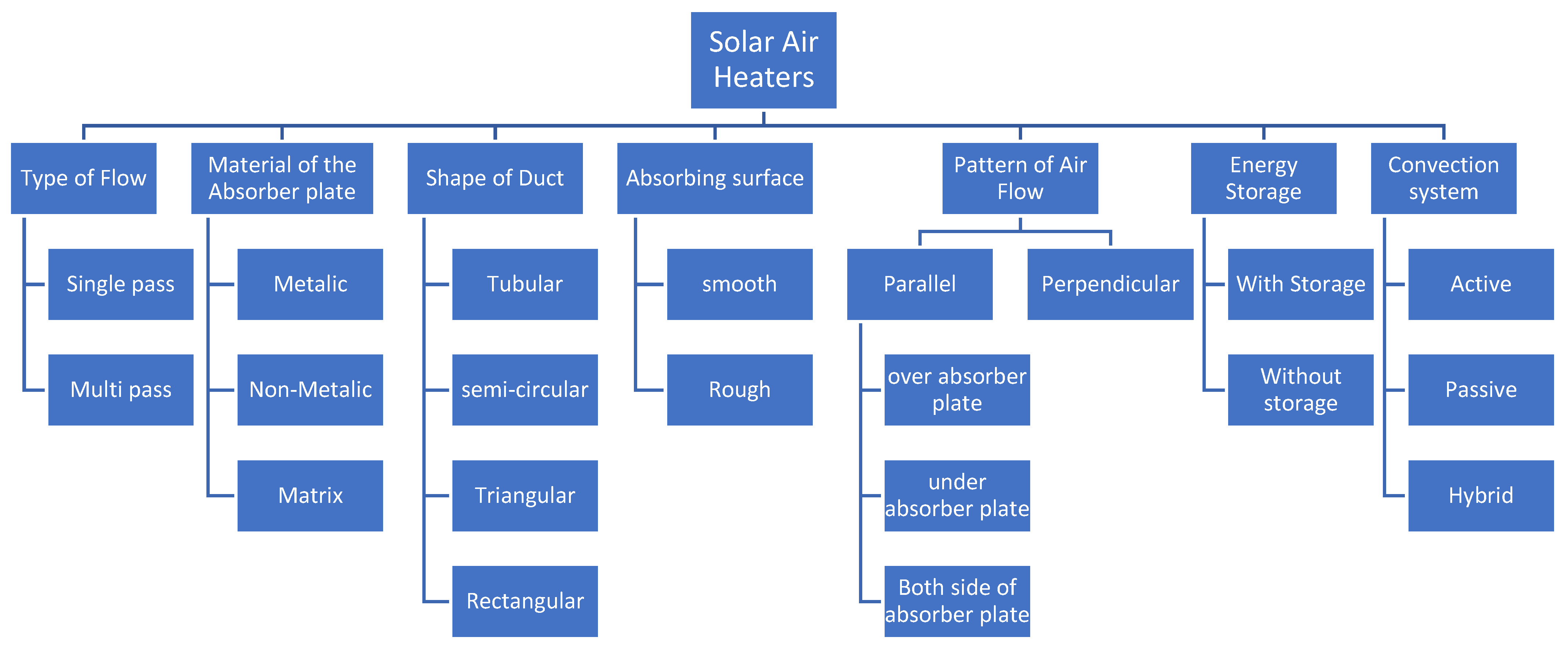
SAHs can be classified in different ways depending on their design and operating principles. As shown in Figure 2, they can be categorised based on the type of air flow, material of the absorber plate, duct shape, absorbing surface, air flow pattern, energy storage, and convection system. Each of these parameters affects how efficiently the system converts sunlight into usable thermal energy.
For example, the type of flow can be single-pass or multi-pass, which determines how many times air travels over the heated surface. Similarly, absorber plates can be metallic, non-metallic, or matrix type, each offering different thermal properties and durability. The shape of the duct, whether tubular, semi-circular, triangular, or rectangular, also plays a crucial role in controlling airflow and heat transfer.
Other factors, such as smooth or rough absorber surfaces, influence how much heat is absorbed and retained. The pattern of airflow can be parallel or perpendicular, with variations depending on whether air passes over, under, or along both surfaces of the absorber sheet. Finally, solar air heaters may include energy storage for continuous operation or function without storage, and they can operate using active, passive, or hybrid convection systems. Together, these design choices make solar air heaters versatile and adaptable for a broad spectrum of uses. Figure 3 presents multiple design layouts of solar air heaters, providing a comparative view of their construction and operation.

1.1. Thermal Efficiency of a SAH [15]

The thermal efficiency (ηth) of an SAH is described as the proportion of effective thermal energy absorbed by the working fluid compared to the overall solar energy striking the absorber surface:
ηth = Q˙u/Q˙A
where:
u is the effective thermal energy absorbed by the fluid, and
A is the overall solar energy striking the absorber surface.
The absorbed solar energy by the absorber sheet is expressed as [15]:
A = Ir × τ × Ac
where:
Ir = solar irradiance (W/m2)
τ = transmissivity of the glass covering
Ac = Total area of the absorber sheet (m2)
The useful heat transfer to the fluid is given by [15]:
u = ṁf × Cpf × (Tfo − Tfi)
where:
f = mass flow rate of the fluid (kg/s)
Cpf = specific heat capacity of the fluid (J/kg·K)
Tfo and Tfi = outlet and inlet temperatures of the fluid, respectively (°C or K)
Thus, the thermal efficiency can also be represented as [15]:
ηth = (ṁf × Cpf× (Tfo − Tfi))/(Ir × τ × Ac)
This equation quantifies how effectively the solar radiation falling on the collector is transformed into heat energy carried by the fluid.
To more accurately describe the heat transfer behaviour along the air flow path, the differential energy balance for an infinitesimal segment dx of the solar air heater duct can be expressed as [16]:
dTf/dx = (h × P × (Tp − Tf))/ṁf × Cpf
In this expression, Tp and Tf refer to the local absorber plate and fluid temperatures, respectively, while h is the convective heat transfer coefficient and P is the heated boundary perimeter.
By integrating Equation (5) along the duct length L, the outlet temperature of the working fluid can be determined as [16]:
Tfo = Tfi + (Tp − Tfi)(1 − e(−(hPL/(ṁfCpf)))
By substituting this relation into Equation (4), the thermal efficiency can be evaluated with improved accuracy.
Under steady-state and one-dimensional flow conditions, Equation (5) can be solved analytically. However, when spatial variations in h, T, p, or fluid properties are notable, numerical schemes such as finite difference or finite element methods are employed. This analysis enhances understanding of local heat transfer and aids in refining roughness geometry and flow design.

1.2. Thermal and Fluid Flow Aspects

The efficiency of a SAH largely depends on the heat exchange between the absorber sheet and the passing air. Turbulent airflow tends to transfer heat more effectively than laminar flow, and specific roughened patterns are used to induce turbulence and enhance fluid mixing. However, while such roughness geometries improve heat transfer, they also typically raise the pressure loss throughout the system. Therefore, assessing the performance of these enhancements requires a balanced evaluation that considers both thermal and hydraulic effects.
The heat transfer between the absorber plate and the flowing air is primarily determined by the convective heat transfer coefficient ( h ), which is influenced by the air velocity, flow regime, and surface roughness characteristics. For artificially roughened surfaces, the Nusselt number ( N u ) can be correlated with the Reynolds ( R e ) and Prandtl ( P r ) numbers as:
N u = C R e m P r n
where C , m , and n are empirical constants dependent on the roughness geometry and flow conditions [16].
Similarly, the friction factor ( f ), representing the pressure drop due to surface roughness, can be expressed as:
f = K R e p
where K and p  are constants determined experimentally for specific duct configurations [16].

1.2.1. Thermo-Hydraulic Parameter

Since improvements in heat transfer are often accompanied by increased frictional losses, relying solely on heat transfer rates can give a misleading impression of overall system performance. To more accurately evaluate the effectiveness of different roughness geometries, a parameter described as the Thermo-Hydraulic Performance Parameter (THPP) is used. Originally proposed by Lewis in 1975, this parameter quantifies the heat transfer enhancement of a roughened surface relative to a smooth one, while accounting for the associated frictional penalty. It serves as a critical metric in identifying the optimal roughness configuration that maximises heat transfer without significantly increasing energy loss due to friction.
Here is a breakdown of the formula [15]:
T H P P = S t / S t s f / f s 1 3  
where:
St (Stanton number) and f (friction factor) for the roughened surface, and respective values of Sts and fs for the smooth surface.
Interpretation:
  • This parameter evaluates the proportional improvement in heat transfer (numerator) to the rise in frictional losses (denominator).
  • A value of THPP > 1 indicates that the roughened surface improves thermal performance more than it increases friction losses; thus, it is considered beneficial.
  • The exponent 1/3 reflects the trade-off between pumping power and heat transfer in a thermodynamically balanced way.

1.2.2. Exergy Analysis of Solar Air Heater

The exergy analysis provides insight into the quality and usefulness of the energy extracted by the solar air heater (SAH). Unlike thermal analysis, which evaluates the quantity of heat gained, exergy analysis quantifies the maximum useful work that can be obtained from that energy under given environmental conditions.
The rate of exergy input from solar radiation to the collector is given by [17,18,19]:
E ˙ i n = A c I ( 1 T a T s )
where A c   is the collector area (m2), I is the solar irradiance (W/m2), T a is the ambient temperature (K), and T s is the apparent sun temperature.
The exergy associated with the useful heat gain by the air stream is expressed as [17,18,19]:
E ˙ u = m ˙ C p [ ( T o T i ) T a l n ( T o T i ) ]
where m ˙ is the mass flow rate of air (kg/s), C p is the specific heat capacity of air (J/kg·K), and T o and T i are the outlet and inlet temperatures (K), respectively.
The exergy efficiency ( η e x ) of the solar air heater is then defined as the ratio of the useful exergy gain to the exergy input from the incident solar radiation [17,18,19]:
η e x = E ˙ u E ˙ i n
This parameter provides a measure of how effectively the system converts the available solar exergy into useful heating of air. Exergy efficiency is typically lower than thermal efficiency, as it accounts for irreversibilities such as frictional losses, heat dissipation, and entropy generation in the flow domain [17,18,19]. Therefore, incorporating exergy analysis offers a more comprehensive evaluation of solar air heater performance, allowing the identification of configurations that not only maximise heat transfer but also optimise energy quality and system sustainability.

2. Influence of Various Factors on the Thermal Efficiency of SAHs

The efficiency of a SAH depends on a variety of interrelated factors, which can be broadly categorised into three main groups:
i.
System Parameters
  • Number of Glass Covers: Optimal performance is generally achieved with 1 or 2 glass covers, based on whether the absorber surface is selective in nature.
  • Emissivity of Glass Cover: A lower emissivity value minimises thermal losses, thereby enhancing the overall efficiency of the system.
  • Spacing between Plate and Glass Cover: Since collectors are designed for use under different tilt angles and environmental conditions, there is no fixed optimal spacing. However, a typical gap of 1 to 4 cm is commonly adopted in practical applications.
ii.
Operational Parameters
  • Inlet Air Temperature: With a rise in the temperature of the entering air, the performance of the absorber sheet tends to decline.
  • Mass Flux of Air: Increasing the flow rate of the working fluid generally leads to an increase in the collector’s thermal efficiency as a result of enhanced heat exchange.
iii.
Meteorological Parameters
  • Solar Irradiance: Higher levels of incident solar radiation contribute to improved collector efficiency for a fixed inlet air temperature.
  • Wind Speed: Greater wind velocities increase thermal losses occurring at the surface of the collector to the environment, thereby reducing efficiency.
  • Dust Accumulation on Glass Surface: The presence of dust on the top cover can block or scatter incident solar radiation, lowering the amount of energy transmitted to the absorber and thus decreasing overall performance.

3. Overview of Studies on Heat Transfer Enhancement Using Induced Roughness over Absorber Sheets

Mondloe et al. [20] investigated the effect of transverse wire rib roughness with different gap configurations on the performance of flat plate solar air heaters. Five absorber plate designs were experimentally tested under outdoor conditions in Jagdalpur, India, at varying air mass flow rates. The study revealed that ribbed plates, particularly those with two gaps, achieved notable improvements in both thermal and exergetic efficiencies compared to smooth surfaces. The findings emphasised the importance of optimising rib geometry to enhance energy conversion and recommended further research on modelling, alternative surface coatings, and sustainability assessment. However, the study’s scope was limited to specific climatic conditions and a narrow range of flow parameters, which might have affected the general applicability of the results to other operating environments. Sastry et al. [21] examined the use of equilateral triangular turbulence promoters in solar air heaters to enhance heat transfer by disturbing the laminar sublayer and inducing secondary vortices. Through CFD simulations, the study analysed the effects of rib height, rib spacing, and Reynolds number on thermal and hydraulic performance. The optimised triangular roughness configuration produced a marked increase in heat transfer relative to smooth ducts, albeit with a moderate rise in frictional losses. Correlations were also developed to predict heat transfer and friction factors accurately. However, the analysis was limited to numerical simulations without experimental validation, and the findings might have varied under real outdoor operating conditions. Sawaitul et al. [22] presented a 2D numerical investigation of a SAH with a hybrid rib design combining hyperbolic and airfoil shapes to improve turbulence and heat transfer. For a rib pitch of 10 mm, the Nusselt number (Nu) showed an increase of 0.4873, whereas the friction factor experienced a rise of 2.9158. At a rib pitch of 20 mm, the Nusselt number improved further by 0.6522. The results showed that the modified ribs enhanced heat transfer due to convection; however, this resulted in higher flow resistance.
Singh et al. [23] evaluated the thermal and fluid flow performance of an SAH equipped with an absorber sheet having S-shaped ribs. The results showed that heat transfer improved by 247.5%, whereas the friction factor increased by 478% in relation to a smooth duct. Ribs featuring a 10 mm spacing and different arc angles further enhanced thermal efficiency by 0.2031.
Kaya [24] conducted an experimental comparison of two solar air heater designs of identical dimensions; one incorporating an internal zigzag strip (Collector I) and the other featuring hollow cavities (Collector II). Airflow was introduced from the bottom to assess their thermal and exergetic performance. Based on the second law of thermodynamics, Collector I achieved an efficiency range of 0.202–0.388, while Collector II recorded 0.17–0.322, confirming the superior effectiveness of the zigzag configuration. However, the study was limited to a small-scale setup under controlled laboratory conditions, and further testing under variable climatic environments was needed to validate large-scale applicability. Vinothkumar et al. [25] numerically investigated flat and V-grooved solar air heaters equipped with hexagonal baffles to enhance heat transfer. Using ANSYS (2020 R1 version) Fluent, the results showed that the V-grooved configuration achieved a thermal efficiency of 0.5495 at a mass flow rate of 6 × 10⁻² kg/s. Peak outlet air temperatures of 59 °C and 69 °C were observed for flat and V-grooved plates at 0.01 kg/s, respectively. The addition of baffles improved efficiency, with the thermal enhancement factor (TEF) ranging from 126% to 228%. However, the study was limited to numerical analysis and did not include experimental validation, which was essential to confirm the model’s accuracy under real operating conditions. Sharma et al. [26] employed CFD analysis to assess the performance of solar air heaters featuring C-shaped, reverse C-shaped, and reverse R-shaped ribs on the absorber surface. Simulations conducted for Reynolds numbers between 4000 and 18,000 demonstrated that ribbed geometries enhanced the Nusselt number by 250–330% and the friction factor by 280–505% compared to smooth ducts. Among all tested configurations, the C-shaped rib achieved the best results, with a thermo-hydraulic performance factor of 200.78% at Re = 4000. However, as the study was based solely on numerical simulations, the results might have varied under experimental or outdoor operating conditions, necessitating further validation for practical applications. Patel JP et al. [27] combined CFD, Artificial Neural Networks, and experiments to improve solar air heater performance using aerofoil-Coanda ribs. The design achieved a 2.4564 rise in Nusselt number and a peak THPP of 287% at Re 14,000. ANN optimisation produced a THPP that was 8.648% higher than ANSYS predictions, while experimental results (307%) closely matched theoretical values (312%). The study demonstrated how aerodynamic design and computational tools together can maximise efficiency in solar air heaters. The study effectively validated the ANSYS and ANN-optimised Coanda bump aerofoil roughness through experimental testing; however, it was limited to a specific range of flow conditions and geometric parameters. The influence of varying climatic conditions and long-term operational stability was not addressed, which might have affected the general applicability of the results to large-scale or real-world solar air heating systems.
Chaudhary et al. [28,29] examined rhombus-shaped roughened solar air collectors under outdoor conditions, showing significant efficiency gains compared to smooth plates. The best outcome was recorded with a thermal efficiency (ηth) of 0.7948 at specific roughness parameters, giving a 0.53 improvement over smooth surfaces. The design enhanced heat transfer by increasing turbulence and breaking the laminar sublayer, though with added friction losses. Climatic factors such as solar irradiance, ambient temperature, airflow, moisture, dust, and shading were also found to strongly influence overall system performance. Under moderate conditions of 450–940 W/m2 solar intensity and 25–35 °C ambient temperature, the system achieved its highest efficiency of about 79.5%, demonstrating an effective balance between heat transfer enhancement and frictional losses.
Adavi et al. [30] conducted a two-dimensional numerical study on a solar air collector featuring a pentagonal corrugated absorber plate to enhance the efficiency of solar dryers. Using ANSYS Fluent, the effects of pitch variation and Reynolds number were analysed, revealing that the corrugated design improved heat transfer by 181–288% compared to a flat plate. The optimal configuration, with a pitch of 150 mm and Re = 1800, achieved a peak thermo-hydraulic performance parameter (THPP) of 174.8%. The results showed good agreement with previous studies, confirming the model’s reliability. However, the analysis was restricted to 2D numerical modelling, without experimental validation or assessment under dynamic environmental conditions, which limited its direct applicability to real-world solar drying systems. Dong Z et al. [31] investigated a flat-plate SAH with slanted groove ripple surfaces to enhance heat transfer and efficiency. By varying the amplitude of the groove, the angle of attack, and the array number at Reynolds numbers between 12,000 and 24,000, the design produced axial swirling motions that enhanced fluid mixing. The Nusselt number rose by 121% to 338%, while the friction factor (f) increased by 154% to 696%. Overall, the ripple surface heater achieved 104% to 194% higher heat transfer than a smooth duct at the same energy input.
Kumar et al. [32] investigated a solar heat exchanger incorporating rectangular protrusions on a triangular duct absorber plate to enhance heat transfer performance. Compared to a smooth configuration, the protruded design increased the Nusselt number by 2.45 times at w/e and l/e ratios of 11. Although the protrusions caused a higher pressure drop, the resulting heat transfer improvement outweighed the associated losses, leading to a 1.87-fold rise in the thermo-hydraulic performance parameter (THPP). However, the study was conducted under steady laboratory conditions and did not evaluate long-term operational effects or environmental influences, which might have affected performance consistency in practical applications. Agrawal et al. [33,34,35] examined an SAH duct with double arc-shaped reverse ribs on the absorber sheet in contrast to a plain sheet. The textured surface increased the heat transfer coefficient (h) by 28% to 34% and improved thermal efficiency by about 0.22. However, this enhancement was accompanied by an increase in the friction factor, which grew by 150% to 270% relative to the smooth plate.
Pawar and Hindolia et al. [36] analysed the effect of diamond-shaped roughness on the absorber plate of a solar air heater and compared its performance with that of a smooth duct. The study found that a 15 mm roughness pitch yielded the highest performance, achieving a thermal efficiency of 0.832, approximately 201% higher than the smooth plate. At lower Reynolds numbers around 3000, the difference between roughened and smooth plates was minor; however, the roughened surface provided a clear overall improvement in heat transfer. Despite these promising results, the study was limited to a single geometric configuration and a narrow operating range, leaving scope for further investigation across broader flow conditions and alternative roughness dimensions. Yadav et al. [37] analysed a SAH with square-sectioned transverse ribs on the absorber sheet across Reynolds numbers from 3800 to 18,000. The results showed that rib height and pitch strongly affected fluid motion and thermal transfer, with the Nusselt number increasing by 289% at Re 15,000 and the friction factor rising by 396% at Re 3800. The best THPP was achieved at e/D = 0.042, giving an efficiency of 180% at Re 15,000, making this configuration effective for improvement in thermal transfer. The study was confined to numerical modelling of turbulent flow using square-sectioned transverse ribs and did not include experimental verification. Additionally, the analysis considered idealised flow and thermal boundary conditions, which might not have fully captured the effects of variable solar radiation and real-world operating environments.
Hans et al. [38] explored the effects of rib geometry on heat transfer by analysing factors including rib geometry, inclination angle, gap distance, and the pitch-to-height ratio. They developed relationships for f and h, aiming to identify the most efficient geometry that provided the optimal thermal transfer efficiency for a specific flow resistance. However, the experiments were conducted under controlled laboratory conditions with uniform heat flux, which might not fully represent the variable thermal and flow conditions encountered in practical solar air heater applications.
Jaurker et al. [39] developed correlations for the Nusselt number and friction factor for a rib-grooved configuration in a rectangular solar air heater duct. Their thermo-hydraulic performance parameter (THPP) analysis showed that the rib-grooved geometry provided superior thermal performance compared to the rib-only design. However, the study focused on a limited range of Reynolds numbers and geometric parameters, leaving the influence of wider operating conditions and alternative groove shapes unexplored. Gupta et al. [40] investigated solar air heaters with transverse-wire roughness and demonstrated that these configurations significantly enhanced the thermo-hydraulic performance compared to smooth surfaces. Momin et al. [41] examined V-shaped rib geometries and reported superior heat transfer characteristics due to enhanced flow mixing and turbulence near the absorber plate. Bhagoria et al. [42] evaluated wedge-shaped ribs and established empirical correlations for the heat transfer coefficient and friction factor, confirming notable improvement in thermal performance. Similarly, Sahu et al. [43] studied 90° broken transverse ribs and found that rib discontinuities effectively disrupted the boundary layer, thereby increasing heat transfer rates. Layek et al. [44] conducted a second-law optimisation of solar air heaters with chamfered rib–groove roughness and identified conditions yielding maximum exergy efficiency. Collectively, these studies confirmed that the geometric design of roughness elements plays a decisive role in balancing thermal enhancement and pressure losses. However, each investigation was performed under specific operating conditions and for limited geometric configurations, indicating the need for broader experimental validation and cross-comparative analyses to generalise these findings. Mittal et al. [45] performed a comparative analysis of solar air heaters with different roughness geometries to evaluate their effective efficiency under fixed operating and system parameters. Using previously reported correlations for the heat transfer coefficient and friction factor, the study examined how effective efficiency varied with Reynolds number for both smooth and roughened surfaces. The highest effective efficiency was achieved in the Reynolds number range of 10,000–14,000 under the selected conditions. However, the analysis was limited to specific operating parameters and assumed steady-state conditions, without accounting for the effects of variable solar intensity or transient environmental factors that might have influenced real system performance. According to Whillier A [46], black-painted absorber plates remained the most widely used in SAHs since selective surfaces were difficult to produce. The study emphasised that heat transfer resistance between the flowing fluid and absorber sheet was a key performance limitation, but it could be reduced through low-cost modifications like roughened plates or screens. It also found that, for heating air about 50 °F above ambient, an economical design used a Tedlar cover with airflow beneath a blackened mesh screen.
Thermal energy storage (TES) plays a vital role in ensuring a stable heat supply and enhancing the overall efficiency of solar air heaters, particularly during fluctuating or low solar radiation periods. Recent research highlights that incorporating phase change materials (PCMs) or thermochemical storage substances into solar air heater systems can substantially boost their thermal effectiveness. These materials store surplus heat during high-intensity solar hours and release it when sunlight diminishes. For example, studies conducted by Shchegolkov et al. [47] have demonstrated that the use of paraffin-based PCMs enhanced outlet air temperature stability and improved overall system efficiency. Therefore, integrating TES units into solar air heater configurations offers a practical method to optimise energy use, minimise heat losses, and extend effective operation duration. Recent research has continued to focus on improving the performance of solar air heaters (SAHs) through innovative surface geometries and advanced analytical methods. A recent numerical study by Kumar et al. [48] examined solar air heaters fitted with polygonal-shaped ribs and grooves, reporting notable gains in Nusselt number and thermo-hydraulic performance compared to conventional rib geometries. Another investigation by Shaik et al. [49] analysed triangular-duct solar air heaters with various artificial roughness elements, showing that optimised rib configurations achieved higher heat transfer enhancement with moderate frictional losses. Recent studies, such as those by Ghanem and Bhosale [50] and Kumar et al. [51], have also incorporated exergy and environmental-economic assessments to evaluate the true sustainability of modified SAH designs. Complementary numerical and experimental works [52,53] have demonstrated that polygonal and honeycomb-shaped ribs can significantly boost heat transfer performance, confirming the growing shift toward optimised and multifunctional absorber surfaces. Recent studies extended solar energy applications beyond conventional air heaters. Sedaghat et al. [54] reported that integrating solar PV systems into portable cabins in Kuwait improved energy efficiency and reduced grid dependence. Likewise, Narayanan et al. [55] found that combining solar thermal collectors with PV panels in Australian homes provided greater economic and environmental benefits than standalone systems. Both studies underscored the importance of system integration and adaptation to local climatic conditions for optimal solar performance.
Table 1 summarises the comparative performance of various rib and baffle geometries investigated under different meteorological and operating conditions. The comparison shows that complex or hybrid rib shapes, such as rhombus, diamond, and combined configurations, provide greater heat transfer improvement and thermo-hydraulic performance due to enhanced turbulence and more effective disruption of the thermal boundary layer. The comparisons presented in Table 1 are based on fundamental performance parameters such as thermal efficiency, friction factor, Nusselt number improvement, and thermo-hydraulic performance factor (THPP). These metrics provide a consistent basis for evaluating the heat transfer and flow characteristics of different rib and baffle geometries, ensuring that the results from various studies can be compared on a common and valid ground.
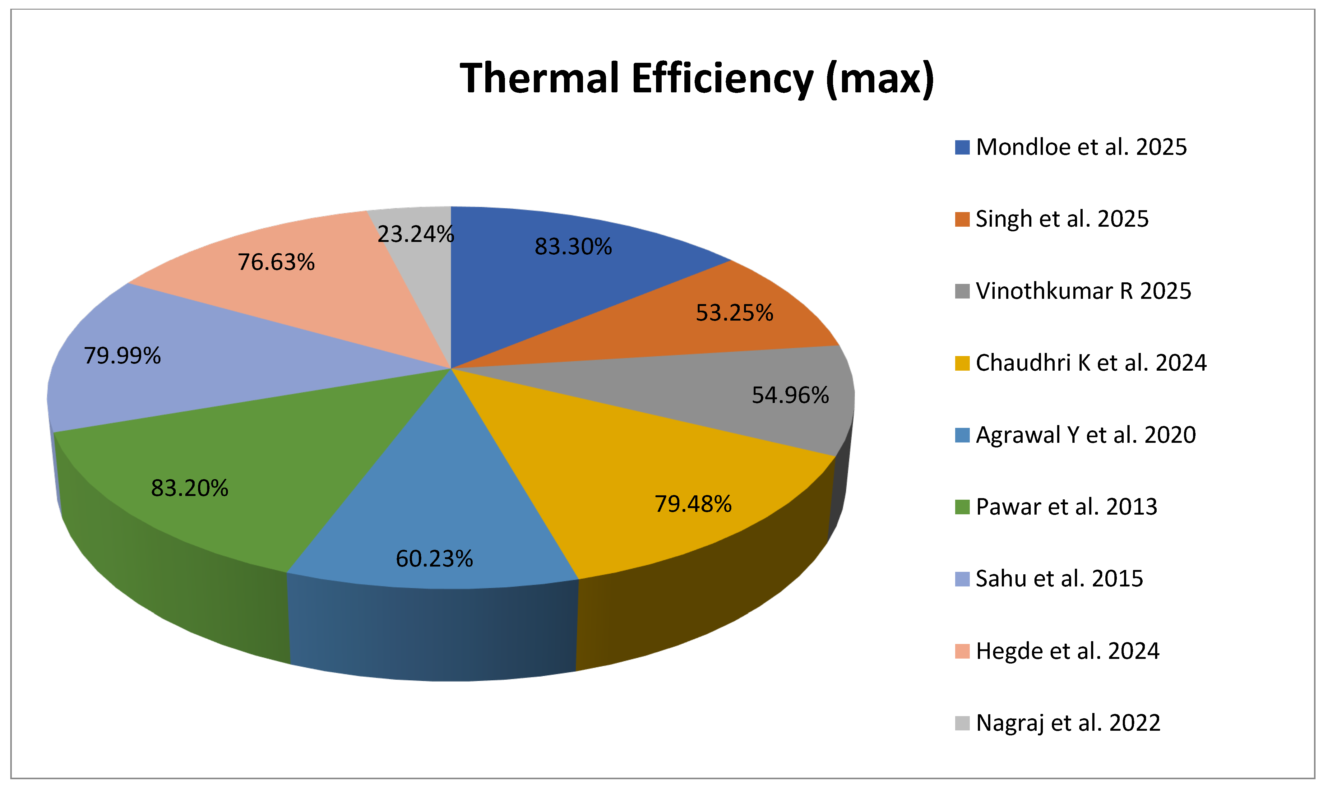
Figure 4 illustrates the maximum thermal efficiency achieved using various rib and baffle configurations reported in previous studies. Among the compared geometries, the transverse wire rib roughness with different gaps [20] and the diamond-shaped rib [36] show the highest thermal efficiencies, both exceeding 83%. In contrast, the S-shaped configuration [23] exhibits the lowest performance at 23.24%. Intermediate results are observed for the hexagonal baffles [25], double arc reverse-shaped [33], and discrete arc-shaped ribs [58], which fall within the range of 54–80%. Overall, the comparison highlights that transverse rib and diamond-shaped geometries are more effective in enhancing heat transfer performance compared to other shapes. It is important to note that the reported efficiencies are based on specific experimental and environmental conditions from each study, and actual performance may vary with changes in atmospheric or operating parameters.
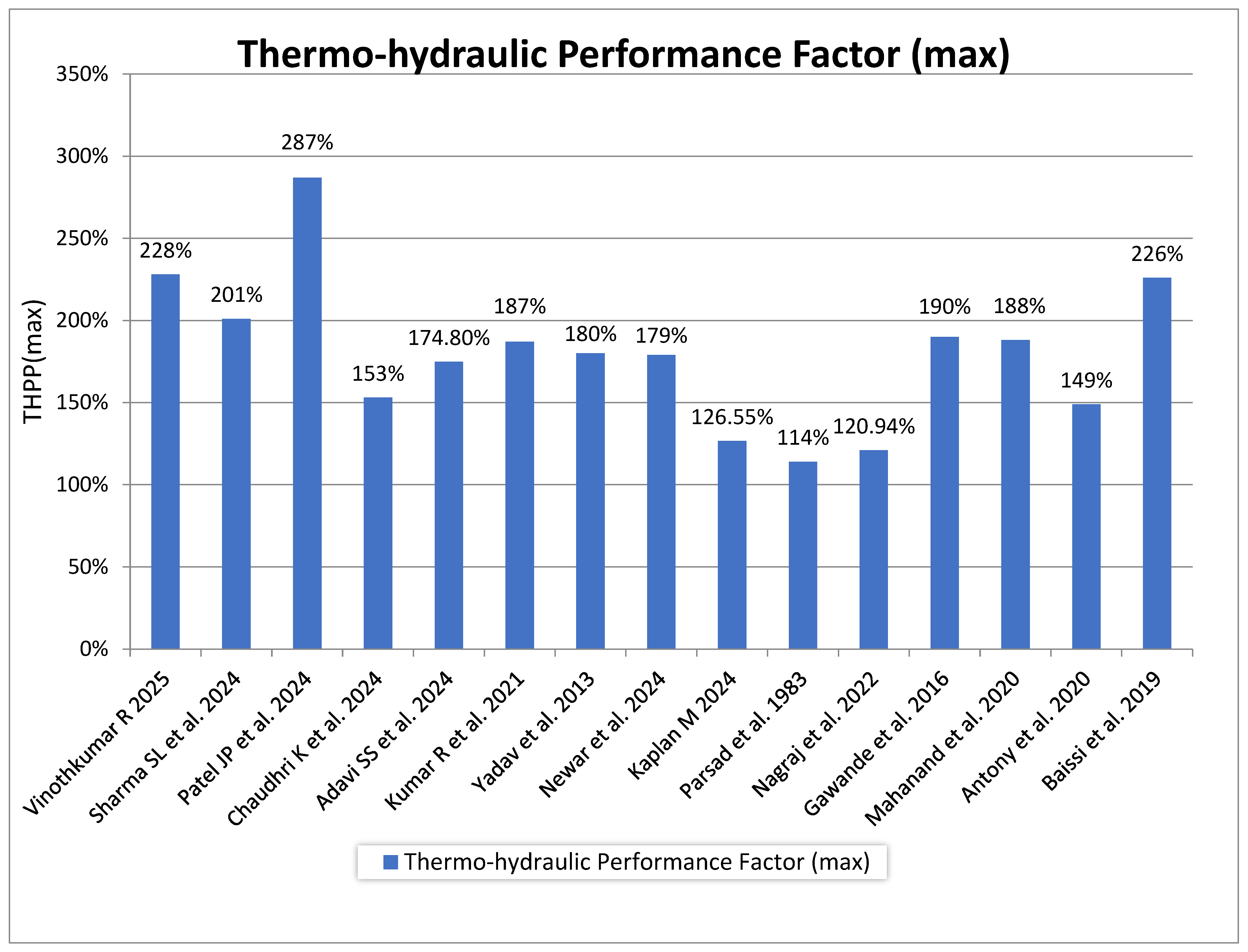
Figure 5 presents the maximum thermo-hydraulic performance factors obtained for different rib and vortex generator configurations reported in earlier studies. The results show that the combined rectangular and semi-circular ribs [56] deliver the highest enhancement, reaching around 300%, followed by the inclined ribs at 45° [60] and the delta-shaped vortex generator [76], both exceeding 200%. Moderate improvements are observed for the hexagonal baffles [25], V-shaped ribs [30], and aerofoil-based designs [27], while the rhombus [28] and square-sectioned transverse ribs [37] exhibit comparatively lower performance levels. Overall, the figure indicates that complex or hybrid rib geometries tend to provide better thermo-hydraulic performance than simple rib shapes, owing to improved turbulence generation and heat transfer characteristics.
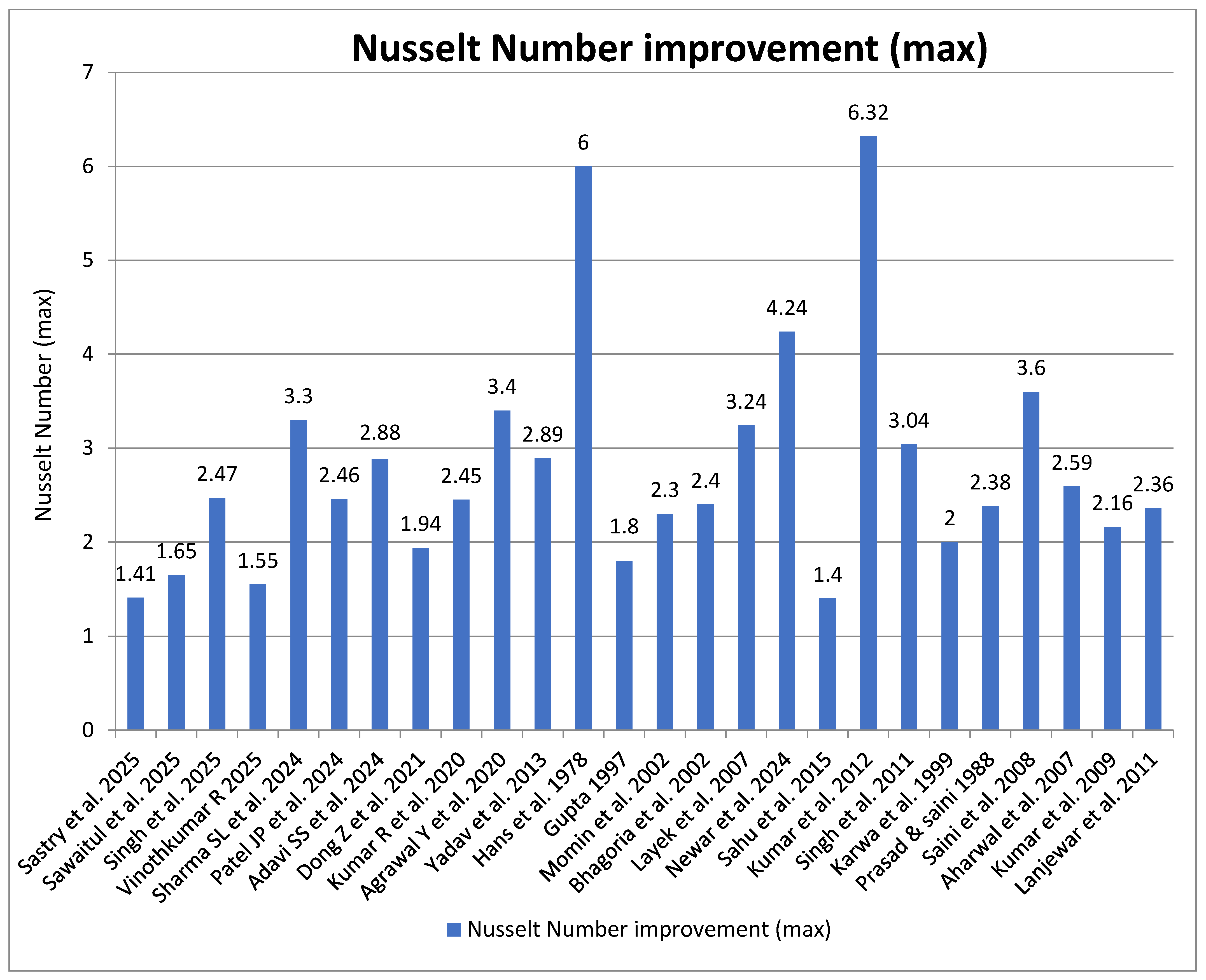
Figure 6 compares the maximum Nusselt number improvement achieved by various rib and surface modification techniques. The equilateral triangular roughness [21] and inclined groove ripple surfaces [31] exhibit the highest enhancements, with maximum Nusselt number ratios of 6.32 and 6.0, respectively. These configurations significantly outperform conventional rib geometries due to their ability to induce strong secondary flows and disrupt the thermal boundary layer. Other geometries, such as hyperbolic airfoil shapes [22], hexagonal baffles [25], and combined rectangular-semi-circular ribs [56], also show notable improvements ranging between 3 and 4.5. In contrast, simpler shapes like S-shaped [23] and chamfered rib [64] arrangements result in comparatively lower heat transfer enhancement. Overall, the figure demonstrates that optimised, multi-directional rib patterns lead to superior convective heat transfer performance compared to traditional or single-orientation rib designs.
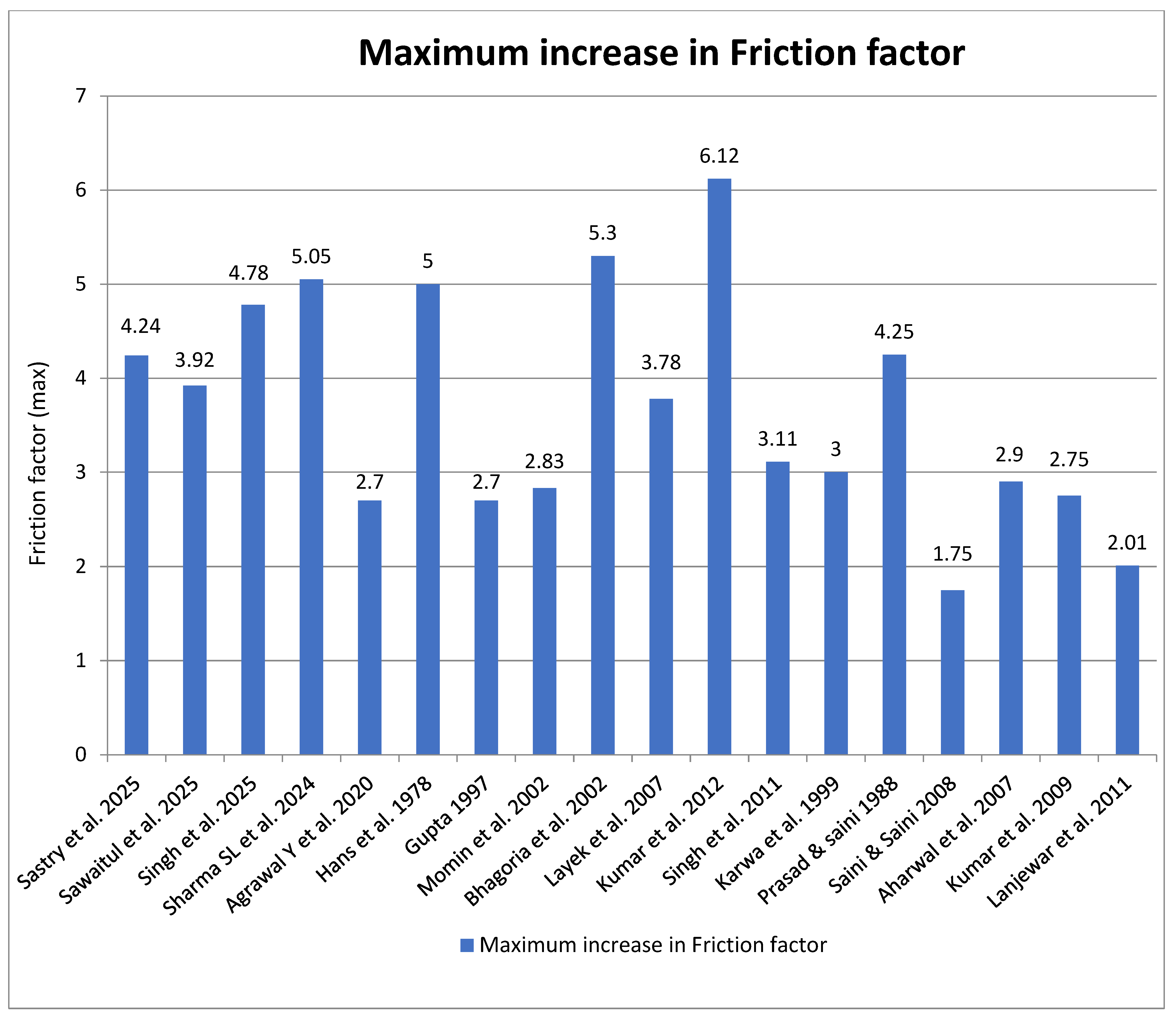
Figure 7 illustrates the maximum increase in friction factor corresponding to different rib and surface roughness geometries. The results show that the equilateral triangular roughness [21] and the multi-V-shaped rib roughness with gaps [62] lead to the highest friction factor increases of 6.12 and 5.3, respectively. These elevated values indicate strong flow disturbances and higher turbulence levels, which enhance heat transfer but also contribute to greater pressure losses. The hyperbolic airfoil [22] and discrete V-down rib configurations [63] also exhibit considerable frictional resistance, with values exceeding 4.0. In contrast, the W-shaped [62] and arc-shaped ribs [66] show comparatively moderate increases, generally below 3.0. Overall, the figure highlights the trade-off between heat transfer enhancement and flow resistance, emphasising the importance of optimising rib geometry to balance performance efficiency and hydraulic losses.

4. Conclusions

The present work provides an in-depth comparative assessment of solar air heaters (SAHs) featuring different artificial roughness geometries, focusing on their collective impact on heat transfer coefficient, friction factor, thermal, and thermo-hydraulic performance. Unlike earlier works that primarily examined individual parameters, the present analysis integrates multiple performance aspects to identify configurations that achieve a balanced improvement between efficiency and pressure drop. The study further consolidates experimental and analytical findings from diverse sources into a unified framework, providing deeper insight into how geometric modifications affect overall system performance. This integrated approach contributes to refining the design and optimisation of solar air heaters for enhanced energy efficiency and reliability.
This study presents a comprehensive evaluation of solar air heaters (SAHs) incorporating various artificial roughness geometries to identify configurations that deliver superior thermal and thermo-hydraulic performance. As depicted in Figure 4, the highest thermal efficiencies were achieved with transverse wire ribs with multiple gaps (83.3%) and diamond-shaped ribs (83.2%), establishing these geometries as the most promising for improved heat absorption. Figure 5 demonstrates that aerofoil-Coanda ribs and hexagonal baffle designs provided the greatest thermo-hydraulic performance enhancements, with increases of 287% and 228%, respectively. In terms of heat transfer characteristics (Figure 6), the multi-V-shaped rib profile yielded over sixfold improvement in the Nusselt number compared to a smooth duct, while the combined rectangular and semi-circular rib configuration achieved a 4.24-fold enhancement. Furthermore, Figure 7 reveals the effect of rib shape on frictional losses, where the highest friction factors were observed for multi-V-shaped ribs with gaps (6.12) and transverse wedge-shaped ribs (5.30). Conversely, the lowest penalties were associated with arc-shaped ribs (1.75) and W-shaped ribs (2.01), suggesting a more favourable compromise between heat transfer efficiency and pressure drop.
The overall comparison of artificial roughness geometries shows that complex and hybrid rib configurations deliver the most effective balance between improved heat transfer and manageable frictional losses. This analysis provides a useful reference for selecting or designing optimal roughness geometries to enhance the performance and efficiency of future solar air heater systems.

Author Contributions

Conceptualization, R.S. and R.N.; Methodology, R.S. and R.N.; Software, R.S. and R.N.; Validation, R.S. and R.N.; Formal analysis, R.S. and R.N.; Investigation, R.S. and R.N.; Resources, R.S. and R.N.; Data curation, R.S. and R.N.; Visualization, R.S. and R.N.; Writing—original draft, R.S.; Writing—review & editing, R.N.; Supervision, R.N.; Project administration, R.N.; Funding acquisition, R.N. All authors have read and agreed to the published version of the manuscript.

Funding

This research received no external funding.

Data Availability Statement

The original contributions presented in the study are included in the article, further inquiries can be directed to the corresponding author.

Conflicts of Interest

The authors declare no conflict of interest.

Nomenclature

D or Dhduct hydraulic diameter (mm)
eheight of rib (mm)
Hduct depth (mm)
gGap width
tgthickness of the collector edge
Isolar irradiance (W/m2)
Ppitch (mm)
Wduct width (mm)
Dimensionless parameters
d/w relative gap position
e/Dhrelative roughness height
g/erelative gap width
g/P relative groove position
Gd/Lvrelative gap distance
L/D test length to hydraulic diameter ratio of the duct
P/erelative roughness pitch
W/Hduct aspect ratio
W/wrelative roughness width
Ngnumber of gaps
Nnumber of glass covers
h/Hobstacle relative height
W/Vrnumber of elements
dr/e relative diagonal length
w/erelative-distance-along-duct-width
l/erelative-distance-along-duct-length
PrPrandtl number
ReReynolds number
StStanton number
Nu Nusselt number
ffriction factor
Greek symbols
αangle of arc of attack (degree)
ϕwedge angle of rib (degree)
ηefficiency
Subscripts
aambient
amair mean
ffluid (air)
iinlet
mmean
ooutlet
pmplate mean
rroughened
ssmooth
tturbulent
wwall

Abbreviations

SAHSolar air heater
THPPThermo-hydraulic Performance Parameter
TEFThermal Enhancement Factor
CFDComputational fluid dynamics
TESThermal Energy Storage
PCMPhase Change Material
ANNArtificial Neural Networks
TGTurbulence Generators
VGVortex Generators

References

  1. Duffie, J.A.; Beckman, W.A. Solar Engineering Thermal Processes; John Wiley& Sons: New York, NY, USA, 1991. [Google Scholar]
  2. Sukhatme, S.P. Solar Energy; Tata McGraw Hill Publishing Co.: New Delhi, India, 1984. [Google Scholar]
  3. Veziroghu, T.N. Solar Energy International Progress; Pergamon Press: London, UK, 1980; pp. 167–173. [Google Scholar]
  4. Hsieh, J.S. Solar Energy Engineering; Printice Hall Inc.: Saddle River, NJ, USA, 1986. [Google Scholar]
  5. Saxena, A.; Varun; El-Sebaii, A.A. A thermodynamic review of solar air heaters. Renew. Sustain. Energy Rev. 2015, 43, 863–890. [Google Scholar] [CrossRef]
  6. Varun. Performance evaluation of solar crop dryer integrated with solar air heater. In Proceedings of the 2011 International Conference & Utility Exhibition on Power and Energy Systems: Issues and Prospects for Asia (ICUE), Pattaya, Thailand, 28–30 September 2011; pp. 1–4. [Google Scholar] [CrossRef]
  7. Koyuncu, T. Performance of various design of solar air heaters for crop drying applications. Renew. Energy 2005, 31, 1073–1088. [Google Scholar] [CrossRef]
  8. Habtay, G.; Al-Neama, M.A.; Buzas, J.; Farkas, I. Experimental performance of solar air heaters for drying applications. Eur. J. Energy Res. 2021, 1, 4–10. [Google Scholar] [CrossRef]
  9. Lamrani, B.; Draoui, A.; Kuznik, F. Thermal performance and environmental assessment of a hybrid solar-electrical wood dryer integrated with Photovoltaic/Thermal air collector and heat recovery system. Sol. Energy 2021, 221, 60–74. [Google Scholar] [CrossRef]
  10. Abbas, S.; Hassan, A.; Zhou, J.; Bisengimana, E.; Yousuf, S.; Hassan, M.; Yuan, Y. Progress and challenges in the integration of solar heat pumps with thermal collectors and PCM-based thermal energy storage systems for heating applications. Sol. Energy 2025, 301, 113919. [Google Scholar] [CrossRef]
  11. Vahidhosseini, S.M.; Rashidi, S.; Hsu, S.-H.; Yan, W.-M.; Rashidi, A. Integration of solar thermal collectors and heat pumps with thermal energy storage systems for building energy demand reduction: A comprehensive review. J. Energy Storage 2024, 95, 112568. [Google Scholar] [CrossRef]
  12. Bansal, N.K. Solar air heater applications in India. Renew. Energy 1999, 16, 618–623. [Google Scholar] [CrossRef]
  13. Duhan, S.; Shah, S.; Kesari, J.P. Solar air heating and its applications in agricultural and industrial drying. Int. Res. J. Mod. Eng. Technol. Sci. (IRJMETS) 2021, 3, 7. Available online: https://www.irjmets.com/uploadedfiles/paper/volume3/issue_7_july_2021/14510/1628083565.pdf (accessed on 3 August 2025).
  14. Hans, V.S.; Saini, R.P.; Saini, J.S. Performance of artificially roughened solar air heaters—A review. Renew. Sustain. Energy Rev. 2009, 13, 1854–1869. [Google Scholar] [CrossRef]
  15. Bergman, T.L.; Lavine, A.S.; Incropera, F.P.; DeWitt, D.P. Introduction to Heat Transfer; John Wiley & Sons: New York, NY, USA, 2001. [Google Scholar]
  16. Incropera, F.P.; DeWitt, D.P.; Bergman, T.L.; Lavine, A.S. Fundamentals of Heat and Mass Transfer, 8th ed.; John Wiley & Sons: New York, NY, USA, 2017. [Google Scholar]
  17. Petela, R. Exergy of undiluted thermal radiation. Sol. Energy 2003, 74, 469–488. [Google Scholar] [CrossRef]
  18. Singh, S.; Singh, B. Energy and exergy analysis of solar air heater with inclined perforated baffles. Renew. Energy 2018, 115, 820–831. [Google Scholar]
  19. Esen, H. Experimental energy and exergy analysis of a double-flow solar air heater having different obstacles on absorber plates. Build. Environ. 2008, 43, 1046–1054. [Google Scholar] [CrossRef]
  20. Mondloe, D.S.; Ghritlahre, H.K.; Agrawal, G.K. The evaluation of energetic and exergetic performances of solar air heater using transverse wire rib roughness with various gaps—An experimental study. J. Eng. Appl. Sci. 2025, 72, 89. [Google Scholar] [CrossRef]
  21. Sastry, G.R.K.; Raju, L.B.B.; Gugulothu, S.K.; Ağbulut, Ü.; Barmavatu, P. Thermo-hydraulic optimisation of rectangular duct solar air heaters using equilateral triangular roughness on absorber plates. J. Therm. Anal. Calorim. 2025, 150, 4549–4567. [Google Scholar] [CrossRef]
  22. Sawaitul, A.V.; Sawarkar, S.R.; Jadhav, A.; Kalamkar, V.R. Numerical study of solar air heater with novel rib roughness. Int. J. Energy A Clean Environ. 2025, 26, 59–71. [Google Scholar] [CrossRef]
  23. Singh, R.; Bhagoria, J.L.; Narayanan, R. Experimental Analysis of Thermo-Hydraulic Performance of Quadratic Duct with Artificial Roughness on a Single Broad Heated Surface of the Absorber Plate of Solar Air Heater. Case Stud. Therm. Eng. 2025, 72, 106415. [Google Scholar] [CrossRef]
  24. Kaya, M. Experimental investigation of inside zigzag pipe collector solar air heaters: Energy and exergy analyses. Arch. Thermodyn. 2024, 45, 215–222. [Google Scholar] [CrossRef]
  25. Vinothkumar, R.; Kumaresan, G.; Ahmed, K.R.A.; Saravanan, B. Evaluation of thermo-hydraulic performance of solar air heater integrated with hexagonal baffles: A numerical investigation. J. Therm. Anal. Calorim. 2025, 150, 6429–6445. [Google Scholar] [CrossRef]
  26. Sharma, S.L.; Kishor, K.; Bisht, V.S.; Debbarma, A.; Gaur, A. CFD analysis of artificially roughened solar air heater: A comparative study of C-Shape, reverse C-Shape, and reverse R-Shape roughness element. Int. J. Ambient. Energy 2024, 45, 2331240. [Google Scholar] [CrossRef]
  27. Patel, J.P.; Bhagoria, J.L. Experimental validation of ANSYS and ANN-optimised Coanda bump Aerofoil shaped roughness element for enhanced performance in solar air heating systems. Int. Commun. Heat. Mass. Transf. 2024, 156, 107541. [Google Scholar] [CrossRef]
  28. Chaudhri, K.; Bhagoria, J.L.; Kumar, V. Thermal Performance Investigation of Rhombus Shape Roughened Solar Air Collector- a Novel approach. Renew. Energy 2024, 235, 121305. [Google Scholar] [CrossRef]
  29. Chaudhri, K.; Bhagoria, J.L.; Kumar, V. Heat transfer and friction factor correlation for rhombus-shaped roughness geometry on the absorber plate of solar air collector. J. Therm. Anal. Calorim. 2024, 149, 6405–6420. [Google Scholar] [CrossRef]
  30. Adavi, S.S.; Chandramohan, V.P. Numerical analysis of pentagonal ribbed absorber plate of solar air collector in an indirect solar dryer for enhanced performance. Energy Sources Part A Recovery Util. Environ. Eff. 2024, 46, 3363–3380. [Google Scholar] [CrossRef]
  31. Dong, Z.; Liu, P.; Xiao, H.; Liu, Z.; Liu, W. A study on heat transfer enhancement for solar air heaters with ripple surface. Renew. Energy 2021, 172, 477–487. [Google Scholar] [CrossRef]
  32. Kumar, R.; Kharub, M.; Kumar, V.; Varun, N. Heat augmented due to array of protrusions on absorber plate in solar heat exchanger. Mater. Today Proc. 2020, 38, 2425–2430. [Google Scholar] [CrossRef]
  33. Agrawal, Y.; Bhagoria, J.L. Experimental Investigation of Heat Transfer and Friction with Double Arc Reverse Shaped Roughness on Absorber Plate of Solar Air Heater. Int. J. Eng. Res. Curr. Trends (IJERCT) 2020, 2, 49–50. [Google Scholar]
  34. Agrawal, Y.; Bhagoria, J.L.; Pagey, V.S. Enhancement of thermal efficiency of solar air collector by using discrete double arc reverse shaped roughness on the absorber plate. Mater. Today Proc. 2021, 51, 1548–1553. [Google Scholar] [CrossRef]
  35. Agrawal, Y.; Bhagoria, J.L.; Yugbodh, K.; Jain, E.; Gautam, A. Thermohydraulic performance of solar air heater having discrete double arc roughness elements on absorber plate. Mater. Today Proc. 2022, 68, 326–334. [Google Scholar] [CrossRef]
  36. Pawar, S.S.; Hindolia, D.A.; Bhagoria, J.L. Enhancement of heat transfer coefficient using Diamond shaped roughness on the absorber plate of solar air heater. Int. J. Eng. Res. Appl. (IJERA) 2013, 3, 968–974. [Google Scholar]
  37. Yadav, A.S.; Bhagoria, J.L. Modeling and Simulation of Turbulent Flows through a Solar Air Heater Having Square-Sectioned Transverse Rib Roughness on the Absorber Plate. Sci. World J. 2013, 2013, 827131. [Google Scholar] [CrossRef]
  38. Han, J.C.; Glicksman, L.R.; Rohsenow, W.M. An investigation of heat transfer and friction for rib-roughened surfaces. Int. J. Heat. Mass. Transf. 1978, 21, 1143–1156. [Google Scholar] [CrossRef]
  39. Jaurker, A.R.; Saini, J.S.; Gandhi, B.K. Heat transfer and friction characteristics of rectangular solar air heater duct using rib-grooved artificial roughness. Sol. Energy 2005, 80, 895–907. [Google Scholar] [CrossRef]
  40. Gupta, D.; Solanki, S.C.; Saini, J.S. Thermohydraulic performance of solar air heaters with roughened absorber plates. Sol. Energy 1997, 61, 33–42. [Google Scholar] [CrossRef]
  41. Momin, A.M.E.; Saini, J.S.; Solanki, S.C. Heat transfer and friction in solar air heater duct with V-shaped rib roughness on absorber plate. Int. J. Heat. Mass. Transf. 2002, 45, 3383–3396. [Google Scholar] [CrossRef]
  42. Bhagoria, J.L.; Saini, J.S.; Solanki, S.C. Heat transfer coefficient and friction factor correlations for rectangular solar air heater duct having transverse wedge shaped rib roughness on the absorber plate. Renew. Energy 2002, 25, 341–369. [Google Scholar] [CrossRef]
  43. Sahu, M.M.; Bhagoria, J.L. Augmentation of heat transfer coefficient by using 90° broken transverse ribs on absorber plate of solar air heater. Renew. Energy 2005, 30, 2057–2073. [Google Scholar] [CrossRef]
  44. Layek, A.; Saini, J.S.; Solanki, S.C. Second law optimisation of a solar air heater having chamfered rib–groove roughness on absorber plate. Renew. Energy 2007, 32, 1967–1980. [Google Scholar] [CrossRef]
  45. Mittal, M.; Varun, N.; Saini, R.; Singal, S. Effective efficiency of solar air heaters having different types of roughness elements on the absorber plate. Energy 2006, 32, 739–745. [Google Scholar] [CrossRef]
  46. Whillier, A. Performance of black-painted solar air heaters of conventional design. Sol. Energy 1964, 8, 31–37. [Google Scholar] [CrossRef]
  47. Shchegolkov, A.; Shchegolkov, A.; Demidova, A. The use of nanomodified heat storage materials for thermal stabilization in the engineering and aerospace industry as a solution for economy. MATEC Web Conf. 2018, 224, 03012. [Google Scholar] [CrossRef]
  48. Kumar, B.V.; Selvan, C.P.; Kanna, P.R.; Taler, D.; Szymkiewicz, M.; Taler, J. Numerical investigation of heat transfer enhancement in solar air heaters using polygonal-shaped ribs and grooves. Front. Energy Res. 2023, 11, 1279225. [Google Scholar] [CrossRef]
  49. Shaik, R.; Punna, E.; Gugulothu, S.K. Numerical investigation on comparative performance assessment of solar air heater with different artificial roughness elements in a triangular duct. J. Therm. Eng. 2025, 11, 49–61. [Google Scholar] [CrossRef]
  50. Ghanem, S.R.; Bhosale, A.C. Exergy-energy efficiency and environmental-economic analysis of honeycomb-shaped artificial roughness in solar air heater. Discov. Energy 2025, 5, 34. [Google Scholar] [CrossRef]
  51. Kumar, R.; Sethi, M.; Goel, V.; Ramis, M.K.; AlSubih, M.; Islam, S.; Al Ansari, M.S.; Lee, D.; Wogasso Wodajo, A. Thermal and effective assessment of solar thermal air collector with roughened absorber surface: An analytical examination. Int. J. Low-Carbon. Technol. 2024, 19, 1112–1123. [Google Scholar] [CrossRef]
  52. Kumar, B.V.; Manikandan, G.; Kanna, P.R. Enhancement of heat transfer in SAH with polygonal and trapezoidal shape of the rib using CFD. Energy 2021, 234, 121154. [Google Scholar] [CrossRef]
  53. Mohammad Azim Aijaz, P.N. Ahirwar. Review of the Impact of Artificial Roughness in Solar Air Heaters. Trends Mach. Design. 2024, 11, 1–9. [Google Scholar]
  54. Sedaghat, A.; Kalbasi, R.; Narayanan, R.; Mehdizadeh, A.; Soleimani, S.M.; Malayer, M.A.; Al-Khiami, M.I.; Salem, H.; Hussam, W.K.; Sabati, M.; et al. Integrating solar PV systems for energy efficiency in portable cabins: A case study in Kuwait. Sol. Energy 2024, 277, 112715. [Google Scholar] [CrossRef]
  55. Narayanan, R.; Parthkumar, P.; Pippia, R. Solar energy utilisation in Australian homes: A case study. Case Stud. Therm. Eng. 2021, 28, 101603. [Google Scholar] [CrossRef]
  56. Newar, P.P.; Das, B. Thermal exploration of combined rectangular and semi-circular artificial ribs in the flow regime of solar air heater: A computational and experimental approach. J. Sol. Energy Eng. 2024, 147, 031001. [Google Scholar] [CrossRef]
  57. Gautam, A.K.; Bhagoria, J.L. Performance analysis of double inclination ribbed Solar Air Heater rectangular duct By Liquid Crystal Thermography. Int. Res. J. Eng. Technol. (IRJET) 2016, 3, 6. Available online: https://www.irjet.net/archives/V3/i6/IRJET-V3I6445.pdf (accessed on 5 July 2025).
  58. Sahu, M.M.; Bhagoria, J.L. Experimental Investigation of Heat Transfer and Friction Factor in Solar Air Heater Duct using Discrete Arc Shaped Rib Roughness on Absorber Plate. Int. J. Eng. Res. Technol. (IJERT) 2015, 4, 6. [Google Scholar] [CrossRef]
  59. Hegde, A.K.; Pai, R.; Karanth, K.V. Influence of solar insolation on energy and exergy efficiency of a rectangular duct solar air heater with various types of V rib roughness: An analytical approach. Int. Commun. Heat. Mass. Transf. 2024, 153, 107397. [Google Scholar] [CrossRef]
  60. Kaplan, M. Enhancement of the Thermohydraulic Performance in a Double Passage Square Duct with the Use of Inclined Ribs of 45°: A Comparative Computational Study. Int. J. Energy Res. 2024, 2024, 9935818. [Google Scholar] [CrossRef]
  61. Prasad, K.; Mullick, S.C. Heat transfer characteristics of a solar air heater used for drying purposes. Appl. Energy 1983, 13, 83–93. [Google Scholar] [CrossRef]
  62. Kumar, A.; Saini, R.P.; Saini, J.S. Experimental investigation on heat transfer and fluid flow characteristics of air flow in a rectangular duct with Multi v-shaped rib with gap roughness on the heated plate. Sol. Energy 2012, 86, 1733–1749. [Google Scholar] [CrossRef]
  63. Singh, S.; Chander, S.; Saini, J.S. Heat transfer and friction factor correlations of solar air heater ducts artificially roughened with discrete V-down ribs. Energy 2011, 36, 5053–5064. [Google Scholar] [CrossRef]
  64. Karwa, R.; Solanki, S.C.; Saini, J.S. Heat transfer coefficient and friction factor correlations for the transitional flow regime in rib-roughened rectangular ducts. Int. J. Heat. Mass. Transf. 1999, 42, 1597–1615. [Google Scholar] [CrossRef]
  65. Prasad, B.N.; Saini, J.S. Effect of artificial roughness on heat transfer and friction factor in a solar air heater. Sol. Energy 1988, 41, 555–560. [Google Scholar] [CrossRef]
  66. Saini, S.K.; Saini, R.P. Development of correlations for Nusselt number and friction factor for solar air heater with roughened duct having arc-shaped wire as artificial roughness. Sol. Energy 2008, 82, 1118–1130. [Google Scholar] [CrossRef]
  67. Aharwal, K.R.; Gandhi, B.K.; Saini, J.S. Experimental investigation on heat-transfer enhancement due to a gap in an inclined continuous rib arrangement in a rectangular duct of solar air heater. Renew. Energy 2007, 33, 585–596. [Google Scholar] [CrossRef]
  68. Varun, N.; Saini, R.P.; Singal, S.K. Investigation of thermal performance of solar air heater having roughness elements as a combination of inclined and transverse ribs on the absorber plate. Renew. Energy 2007, 33, 1398–1405. [Google Scholar] [CrossRef]
  69. Kumar, A.; Bhagoria, J.L.; Sarviya, R.M. Heat transfer and friction correlations for artificially roughened solar air heater duct with discrete W-shaped ribs. Energy Convers. Manag. 2009, 50, 2106–2117. [Google Scholar] [CrossRef]
  70. Lanjewar, A.; Bhagoria, J.L.; Sarviya, R.M. Heat transfer and friction in solar air heater duct with W-shaped rib roughness on absorber plate. Energy 2011, 36, 4531–4541. [Google Scholar] [CrossRef]
  71. Sethi, M.; Varun, N.; Thakur, N.S. Correlations for solar air heater duct with dimpled shape roughness elements on absorber plate. Sol. Energy 2012, 86, 2852–2861. [Google Scholar] [CrossRef]
  72. Nagaraj, M.; Reddy, M.K.; Sheshadri, A.K.H.; Karanth, K.V. Numerical analysis of an AerofoilFiN Integrated Double Pass solar air heater for thermal performance enhancement. Sustainability 2022, 15, 591. [Google Scholar] [CrossRef]
  73. Gawande, V.B.; Dhoble, A.S.; Zodpe, D.B.; Chamoli, S. Experimental and CFD investigation of convection heat transfer in solar air heater with reverse L-shaped ribs. Sol. Energy 2016, 131, 275–295. [Google Scholar] [CrossRef]
  74. Mahanand, Y.; Senapati, J.R. Thermo-hydraulic performance analysis of a solar air heater (SAH) with quarter-circular ribs on the absorber plate: A comparative study. Int. J. Therm. Sci. 2020, 161, 106747. [Google Scholar] [CrossRef]
  75. Antony, A.L.; Shetty, S.P.; Madhwesh, N.; Sharma, N.Y.; Karanth, K.V. Influence of stepped cylindrical turbulence generators on the thermal enhancement factor of a flat plate solar air heater. Sol. Energy 2020, 198, 295–310. [Google Scholar] [CrossRef]
  76. Baissi, M.T.; Brima, A.; Aoues, K.; Khanniche, R.; Moummi, N. Thermal behavior in a solar air heater channel roughened with delta-shaped vortex generators. Appl. Therm. Eng. 2019, 165, 113563. [Google Scholar] [CrossRef]
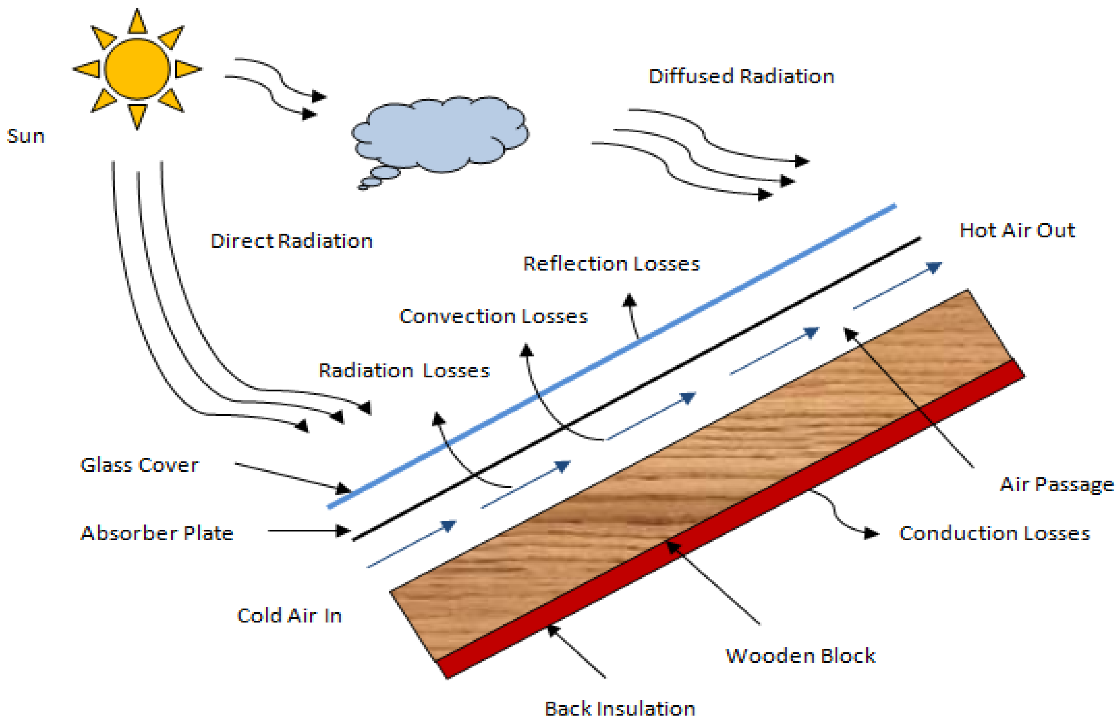
Figure 1. System layout of SAH.
Energies 18 06157 g001
Figure 2. Categorisation of SAHs.
Energies 18 06157 g002
Figure 3. Structural comparison of flat plate, double-pass, V-rib roughened, and porous media solar air heaters.
Energies 18 06157 g003
Figure 4. Thermal efficiency comparison [20,23,25,28,33,36,58,59,72].
Energies 18 06157 g004
Figure 5. Thermo-hydraulic Performance Parameter Comparison [25,26,27,28,30,31,37,56,60,61,72,73,74,75,76].
Energies 18 06157 g005
Figure 6. Comparison of improvement in Nusselt number [21,22,23,25,26,27,30,31,32,33,37,38,40,41,42,44,56,58,62,63,64,65,66,67,69,70].
Energies 18 06157 g006
Figure 7. Comparison of the rise in the friction factor [21,22,23,26,33,38,40,41,42,44,62,63,64,65,66,67,69,70].
Energies 18 06157 g007
Table 1. Comparison of different research outcomes and parameters.
S. No.InvestigatorsGeometryParametersOutcomes
1Mondloe et al. [20]transverse wire rib configuration with multiple gapsNg = 1–4
g = 4 mm
ṁ = 0.01891–0.03937 kg/s
e/D = 0.043
P/e = 10
Dh = 0.0554 m
H = 0.03 m
W = 0.36 m
Max efficiency of 83.3% at Ng = 2, ṁ = 0.0394 kg/s and min efficiency of 16.5% at Ng = 1, ṁ = 0.0244 kg/s.
2Sastry et al. [21]Equilateral Triangular RoughnessP = 10, 15, 20 mm
e = 1.40 mm
P/e = 7.14, 10.42, 14.29
e/D = 0.42
Re = 4000–18,000
Nu increases by 41% at Re 15,000; f increases by 423.9% at Re 5000.
3Sawaitul et al. [22]Hyperbolic airfoil shapeP = 10, 20 mm
e = 0.5, 1 mm
f increased 3.92 times; Nu improved 1.65 times at 20 mm rib pitch.
4Singh et al. [23]S-shapep/e = 8.33
e/Dh = 0.027
W/H = 8
α = 30° to 75°
Re = 3000 to 14,000
Numax = 2.478 and ηthmax = 1.203 times, respectively.
5Kaya M [24]Zig-zag finsṁ = 0.004–0.0098 kg/sA collector with zigzag fins shows up to 20.4% higher exergy efficiency than a hollow collector.
6Vinothkumar R [25]Hexagonal baffles Max thermal efficiency (ηthmax) of 54.96% achieved at 0.06 kg/s and thermal enhancement factor improves from 1.26 to 2.28
7Sharma SL et al. [26]C-shaped, reverse C-shaped, and reverse R-shaped configuration ribsP/e = 14.285
Re = 4000 to 18,000
e/D = 0.021
Numax = 3.3; fmax = 5.05; Max peak THPP of 2.01 at Re 4000 for C-rib configuration.
8Patel JP et al. [27]Aerofoil-Coanda ribsP = 16–36 mm
e = 0.5–1.5 mm
g = 0–16 mm
Re = 3000–18,000
Numax = 2.46 times; peak THPP of 2.87 at Re 14,000.
9Chaudhri K et al. [28]rhombusP/e = 8–12
e/Dh = 0.0225 to 0.03375
W/Vr = 9 to 11
dr/e = 8 to 12
Re = 2000–14,000
Max thermal efficiency of 0.7948 achieved with a 0.53 improvement in thermal performance.
10Adavi SS et al. [30]V-shaped ribsP = 50–175 mm
Re = 1800–15,000
Nu ratio: 1.81–2.88; peak Nu = 2.88. Max Thpp = 1.748 at pitch = 150 mm and Re = 1800.
11Dong Z et al. [31]inclined groove ripple surfacesRe = 12,000–24,000Nu values increased by 1.04–1.94 times.
12Kumar R et al. [32]array of protrusionsP/e = 5 to 15
w/e = 6.5 to 16
l/e = 6.5 to 16
e/D = 0.024
Re = 4800 to 14,500
Numax = 2.45 times; max THPP of 1.87 resulted.
13Agrawal Y et al. [33]Double Arc Reverse ShapedP = 12 mm
e = 1.2 mm
e/Dh = 0.027
Re = 3000–11,000
Max thermal efficiency of 60.23% at Nu = 30.93 and ṁ = 0.02015 kg/s. h increases by 28–34% with f rising from 1.5 to 2.7 times.
14Pawar et al. [36]Diamond shapedW/H = 8
P/e = 10 to 25
e = 1 mm
α = 30°
e/Dh = 0.023
Re = 3000–14,000
Numax = 54.52 at Re = 14,012, and the max thermal efficiency is 83.2%.
15Yadav and Bhagoria [37]Transverse Rib with a Square Cross-SectionW/H = 5
P = 10–28.28 mm
P/e = 14.29
e = 0.7–2 mm
e/Dh = 0.021 to 0.06
Re = 3800 to 18,000
Nu ratio: 1.82–2.89; peak Nu = 2.89 at and Max THPP = 1.8 at Re = 15,000.
16Hans and Glicksman et al. [38]Multiple V-shaped rib profilee/D = 0.019 to 0.043
α = 30° to 75°
Re = 2000 to 20,000
W/w = 1 to 10
P/e = 6 to 12
Numax = 6; fmax = 5
17Gupta [40]Inclined wire rib geometrye/D = 0.018 to 0.032
P/e = 10
Re = 5000 to 50,000
W/H = 6.8 to 11.5
α = 30° to 90°
Numax = 1.8; fmax = 2.7
18Momin and Saini et al. [41]V-shaped rib configuratione/D = 0.02 to 0.034
P/e = 10
Re = 2500 to 18,000
W/H = 10.15
α = 30° to 90°
Numax = 2.30; fmax = 2.83
19Bhagoria and Saini et al. [42]Transverse rib with a wedge-shaped profilee/D = 0.015 to 0.033
P/e = 12.12
ϕ = 8° to 15°
Re = 3000 to 18,000
W/H = 5
Numax = 2.4; fmax = 5.3
20Sahu et al. [43]90° segmented rib geometrye/D = 0.0338
P = 10, 20 and 30
Re = 3000 to 12,000
W/H = 8
e = 1.5
hmax = 1.25 to 1.4 times reported.
21Layek et al. [44]Chamfered rib-grooved profilee/D = 0.022 to 0.040
g/P = 0.3 to 0.6
P/e = 4.5 to 10
ϕ = 5° to 30°
Re = 3000–21,000
Numax = 3.24; fmax = 3.78
22Newar et al. [56]Combined Rectangular and Semi-Circular ribsP = 15 mm
h/H = 0.4–1
I = 400–1000 W/m2
Re = 4000–10,000
Numax = 4.24; TEF peak = 1.79 at Re = 10,000; max exergy efficiency = 11.2%
23Gautam et al. [57]Double Inclination RibbedW/H = 5
P/e = 10
e = 1 mm
α = 60°
e/Dh = 0.034
Re = 4000 to 12,000
Numax = 12.31 at Re = 7749 is obtained.
24Sahu et al. [58]Discrete Arc Shaped RibW/H = 8
P/e = 10
P = 10–20 mm
e = 1–2 mm
α = 30°
e/Dh = 0.0225 to 0.045
Re = 3000 to 14,000
The highest thermal efficiency observed is 79.99% at a roughness pitch of 15 mm.
25Hegde et al. [59]Various types of V rib roughnessI = 800–1200 W/m2
N = 1
tg = 0.040 m
Re = 3000–18,000
The maximum thermal and exergy efficiencies are 76.63% and 5.17%, respectively.
26Kaplan M [60]Inclined Ribs of 45° p/e = 5 to 10
e/Dh = 0.1–0.2
α = 45°
Re = 20,000–40,000
Max THPP increase of 26.55% at Re = 20,000.
27Parsad et al. [61]Transverse wire rib configuratione/D = 0.019
P/e = 12.7
Re = 10,000 to 40,000
Max THPP rise of 14% at Re = 40,000.
28Kumar and Saini et al. [62]Multi-V-shaped rib roughness with gapse/D = 0.043
P/e = 10
Re = 2000 to 20,000
W/H = 12
W/w = 6
g/e = 0.5 to 1.5
Gd/Lv = 0.24 to 0.80
α = 60°
Numax = 6.32; fmax = 6.12
29Singh and Chandan et al. [63]Discrete V-down rib profileP/e = 4 to 12
Re = 3000 to 15,000
d/w = 0.2 to 0.8
α = 30° to 75°
g/e = 0.5 to 2.0
e/D = 0.015 to 0.043
Numax = 3.04; fmax = 3.11
30Karwa and Solanki et al. [64]Chamfered repeated rib-geometryL/D = 32.66
Re = 3000 to 20,000
e/D = 0.014 to 0.032
P/e = 4.5 to 8.5
W/H = 4.8 to 12
ϕ = 15° to 18°
Stmax = 2; fmax = 3
31Prasad and Saini [65]Small dia. protrusion wires.P/e = 10 to 20
Re = 5000 to 50,000
e/D = 0.02 to 0.033
Numax = 2.38; fmax = 4.25
32Saini et al. [66]Arc-shaped rib profileRe = 2000 to17,000
W/H = 12
e/D = 0.0213 to 0.0422
α/90 = 0.3333 to 0.6666
P/e = 10
Numax = 3.6; fmax = 1.75
33Aharwal and Gandhi et al. [67]Slanted continuous rib texture with spacinge and b = 2 mm
g/e = 0.5 to 2
Re = 3000–18,000
d/W = 0.167 to 0.5
W/H = 5.87
e/D = 0.0377
α = 60°
P/e = 10
Numax = 2.59; fmax = 2.9
34Varun and Saini et al. [68]Combined profile of inclined and transverse ribse/D = 0.030
e = 1.6 mm
P/e = 3–8
P = 5–13
Re = 2000–14,000
W/H = 10
The highest thermal efficiency was observed at P/e = 8.
35Kumar and Bhagoria et al. [69]Discrete W-type rib configuratione = 0.75 to 1.5 mm
Re = 3000 to 15,000
W/H = 8
P/e = 10
α = 30–75°
e/D = 0.0168 to 0.0338
Numax = 2.16; fmax = 2.75
36Lanjewar and Bhagoria et al. [70]W-shaped rib profilee = 0.8 to 1.5 mm
Re = 2300 to 14,000
W/H = 8
α = 30–75°
P/e = 10
Numax = 2.36; fmax = 2.01
37Sethi and Varun et al. [71]Dimple-shaped elements arranged in an angular fashionRe = 3600 to 18,000
e/d = 0.5
W/H = 11
e/D = 0.021–0.036
α = 45–75°
P/e = 10 to 20
Numax obtained for P/e = 10.
38Nagraj et al. [72]Aerofoil finI = 950 W/m2
ṁ = 0.00651–0.04614 kg/s
Re = 3000–24,000
Max thermal efficiency and thermo-hydraulic efficiency are 123.24% and 120.94%, respectively.
39Gawande and Dhoble et al. [73]A profile of a Reverse-L shape is usedI = 1000 W/m2
e/D = 0.042
P/e = 7.14–17.86
Re = 3800–18,000
Max THPP of 190% is obtained.
40Mahanand et al. [74]Quarter-circular geometry of ribsI = 1000 W/m2
Re = 3800 to 18,000
e/D = 0.042
P/e = 7.14 to 17.86
Max THPP of 188% is obtained.
41Antony et al. [75]Stepped cylindrical TGP/e = 11.11–27.78
Core dia = 3–7 mm
Re = 3000–24,000
Max THPP of 149% is obtained.
42Baissi et al. [76]Delta-shaped VGα = 45°
e/H = 0.8
Pt/b = 0.6 to 1
Re = 2500–12,000
Pl/e = 3 to 5
Max THPP of 226% is obtained.
Disclaimer/Publisher’s Note: The statements, opinions and data contained in all publications are solely those of the individual author(s) and contributor(s) and not of MDPI and/or the editor(s). MDPI and/or the editor(s) disclaim responsibility for any injury to people or property resulting from any ideas, methods, instructions or products referred to in the content.