3.1. Limitations of Conventional Damping Approaches
In previous studies, methods utilizing the generator speed have been mainly proposed to suppress torsional oscillations occurring in the two-mass model [
10,
11,
12].
As illustrated in
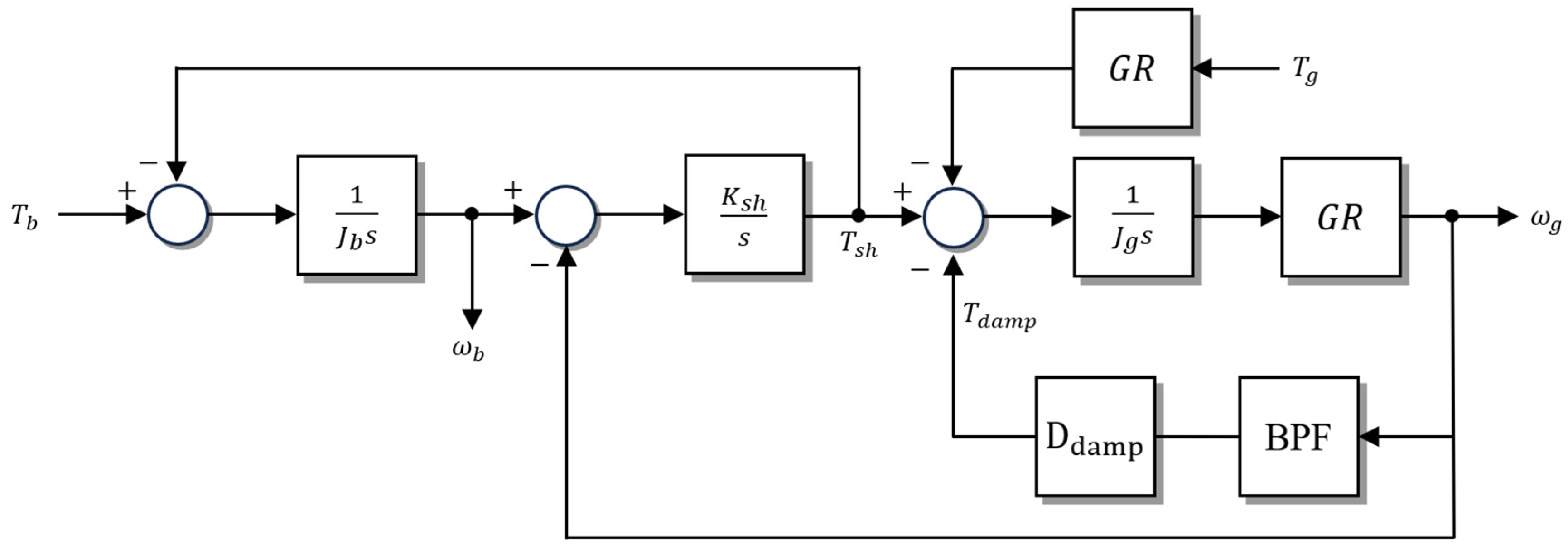
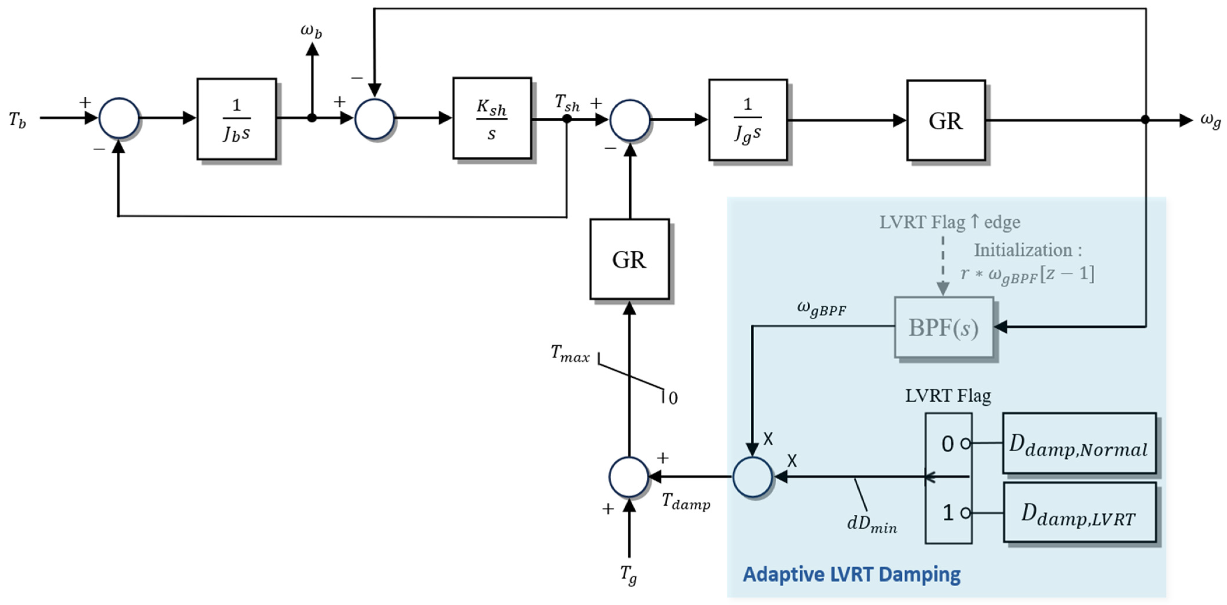
Figure 4, the conventional approach applies a band-pass filter (BPF) to the generator speed
to extract the torsional mode frequency component, which is then multiplied by a damping coefficient (
) to produce the active damping torque (
). The damping torque is then defined as:
Furthermore, from
Figure 4, the torque balance equations for each mass are derived as follows.
From Equation (10), the transfer function relating the generator angular speed
to the generator torque
is obtained as follows.
Substituting the parameter values into Equation (11) allows the constant denominator term (
) to be neglected, yielding the following expression after factoring the s-terms.
Omitting the zero from Equation (12), the transfer function of the generator angular speed is obtained as follows.
Therefore, matching the denominator of Equation (13) to the standard second-order form yields the following relationship.
That is, according to Equation (14), by setting the desired torsional damping ratio
, the corresponding damping coefficient
can be calculated. In previous studies, values of
have mainly been used, and such a range of damping coefficients is generally applied in MW-scale wind turbine drivetrains [
31,
32]. However, this approach suffers from inherent limitations.
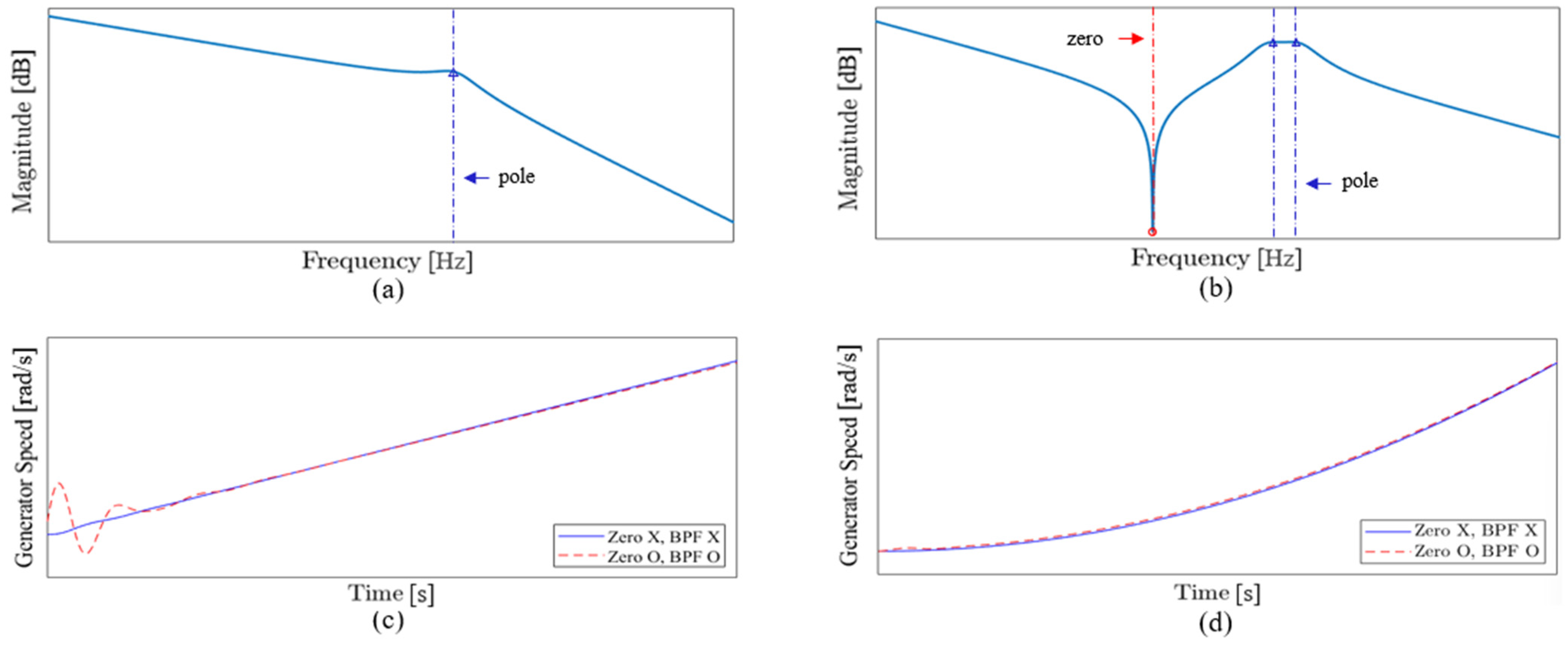
The conventional method determines the damping coefficient by assuming steady-state operation, neglecting the zero in the original transfer function of Equation (12), and matching only the poles to a standard second-order system. As illustrated in
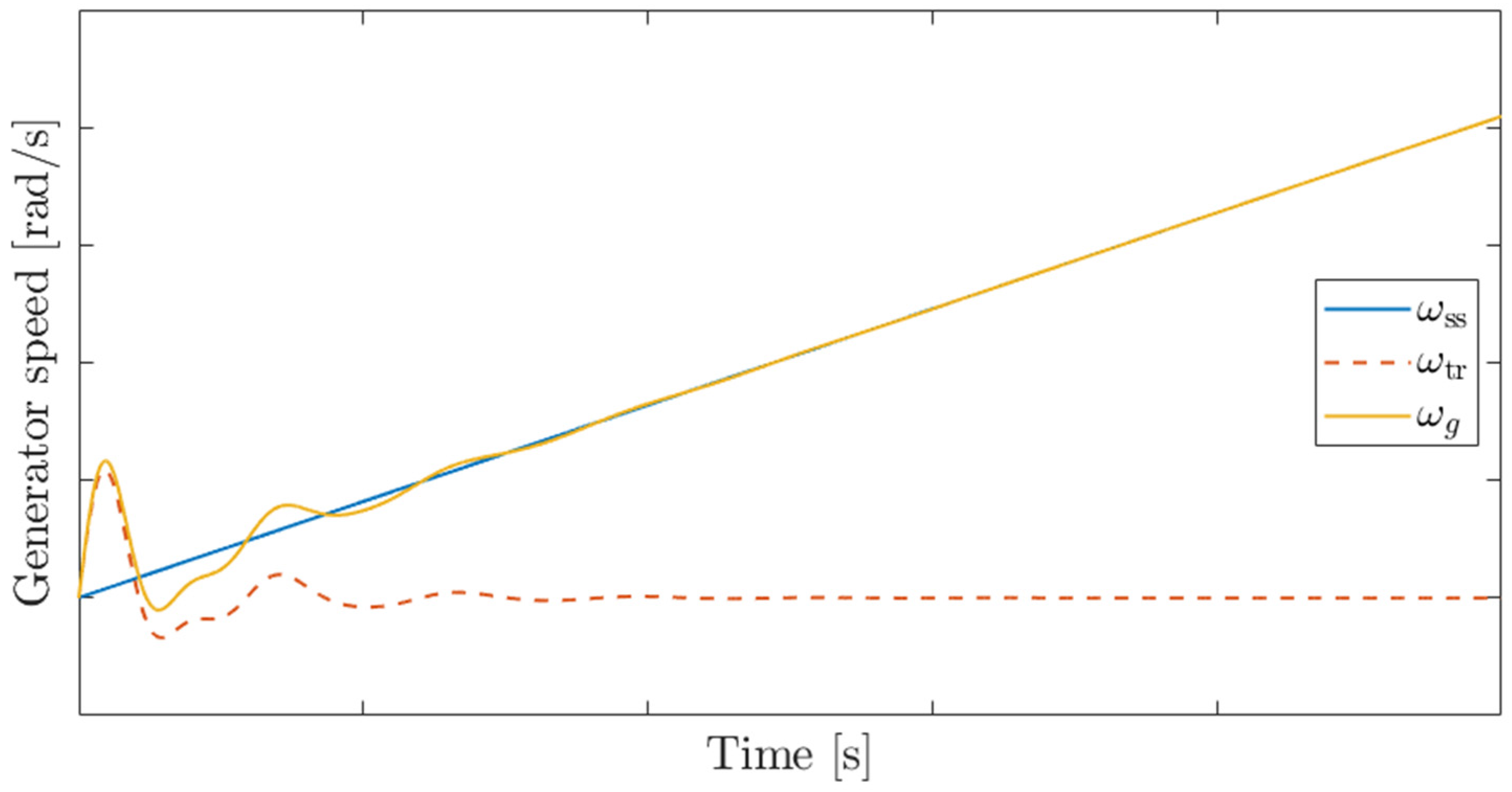
Figure 5d, under a ramp torque input emulating steady-state operation, the generator speed responses are nearly identical regardless of the inclusion of the zero. This confirms that the zero has negligible influence during steady-state operation. Thus, selecting the damping coefficient from the simplified transfer function of Equation (13) without the zero is justifiable.
On the other hand, under transient conditions such as LVRT, as shown in
Figure 5c, overshoot occurs depending on whether the zero is considered.
The conventional method of defining the damping coefficient by considering only the poles of the transfer function may be effective in suppressing resonance under steady-state conditions, but it has limitations in accurately predicting or ensuring suppression of actual shaft torsional oscillations under situations with abrupt torque variations such as LVRT.
Furthermore, previous studies did not consider the transfer function of the BPF used to extract a specific frequency band from the generator speed. The transfer function of the band-pass filter (BPF) is expressed as follows.
Considering the band-pass filter transfer function defined in Equation (15), two closely spaced poles become separated—a phenomenon known as pole-splitting—as illustrated in
Figure 5b. This results in distinct damping ratios and oscillation frequencies, representing the inherent torsional vibration modes of the drivetrain.
The migration of these poles directly influences shaft stability and mechanical stress distribution. In particular, insufficient damping or the movement of poles toward the imaginary axis leads to increased torsional angle overshoot during torque transients, causing accumulated cyclic stress and potential fatigue damage to gears and shafts.
Therefore, under transient conditions such as LVRT, the damping coefficient must be redesigned by incorporating both the band-pass filter (BPF) characteristics and the effects of transmission zeros in the control path. To address this, the present study introduces a new damping coefficient determination approach that constrains the maximum torsional angle of the transient response based on the complete transfer function, including both the zeros and the BPF dynamics.
In summary, the conventional pole-based damping coefficient estimation is effective for resonance suppression under steady-state operation but lacks accuracy under rapidly varying torque conditions, such as LVRT, due to neglecting the BPF phase delay and zero dynamics. This limitation forms the basis for the proposed methodology, which maintains the structural simplicity and practical applicability of conventional methods while simultaneously accounting for pole migration and damping characteristics during transient events. The proposed framework effectively bridges the gap between mathematical idealization and the actual electromechanical behavior of the drivetrain, providing a quantitative design guideline for enhancing mechanical reliability.
Figure 5 illustrates the Bode plots of Equation (13), excluding the zero and BPF transfer function, and Equation (17), including them, along with a comparison of the generator speed responses to a step torque input representing the transient state and a ramp torque input representing steady-state operation. The presented waveforms are illustrative examples, and similar trends are typically observed in MW-scale wind turbines.
3.2. Derivation of Transient Torsional Response for Damping Coefficient Design
The core idea of the proposed approach is to directly compute the maximum shaft torsional angle corresponding to the input torque, given specific parameters and a damping coefficient. To this end, by incorporating the transfer function of the band-pass filter into the transfer function of the generator angular speed with respect to the generator torque defined in Equation (11),
and assuming a step torque as the generator input, the generator speed transfer function can be derived from the two expressions in Equation (16) as follows.
Deriving the time-domain response of the generator speed from this transfer function requires applying the inverse Laplace transform. Accordingly, the transfer function possesses a double pole at
, while the remaining four poles form two pairs of complex conjugates, and it can thus be expressed via partial fraction expansion as follows.
The coefficients
and
obtained through the Taylor expansion are as follows.
For the partial fraction expansion of the poles other than the double pole, the poles of each partial fraction must first be derived. The quartic denominator equation can be solved using the standard Ferrari formula, yielding two pairs of complex conjugate poles as expressed in Equation (20) [
33]. The detailed derivation process for this is provided in
Appendix A.
Here,
and
denote the damping ratio and natural frequency of the high-frequency (fast mode) torsional vibration, corresponding to the elastic deformation of the generator shaft and mechanical coupling components. Conversely,
and
represent the damping ratio and natural frequency of the low-frequency (slow mode) torsional vibration, which arises from the energy exchange between the blade and generator inertias and manifests as a slower torsional response. Typically,
and
; the high-frequency mode contributes to the suppression of transient torsional oscillations through rapid damping, whereas the low-frequency mode tends to sustain residual oscillations over a longer duration. Hence, controlling the damping ratios and amplitudes of both modes is crucial for mitigating shaft fatigue and maintaining dynamic stability of the drivetrain. The residue coefficient
for each pole is
are obtained, and the residue coefficients likewise form complex conjugate pairs.
Therefore, by performing the inverse Laplace transform based on these obtained variables, the time-domain response of the generator angular speed can be expressed as follows.
The time-domain response of the generator speed can be decomposed into steady-state and transient components, with the steady-state component expressed as follows.
The transient component is as follows.
The time-domain response of the generator angular speed, together with its steady-state component and transient component, is shown in
Figure 6.
Under step-like torque disturbances such as LVRT, when the blade inertia is much larger than the generator inertia (
), the blade displacement remains nearly constant, and oscillations occur mainly on the generator side. Therefore, the steady-state component shown in
Figure 6 corresponds to the blade angular speed (
), while the transient component can be interpreted as the relative speed between the blade and the generator (
). Thus, the shaft torsional angle is obtained by integrating the transient component, and evaluating this integral at the instant when the transient component first crosses zero yields the maximum torsional angle of the shaft under a step torque input.
The maximum torsional angle of the shaft, calculated as described above, serves as a key quantitative metric for determining the appropriate level of the damping coefficient
. An excessively large torsional angle increases the cyclic stress amplitude on the shaft surface, accelerating fatigue accumulation. Conversely, applying an overly large damping coefficient over-suppresses the transient response, resulting in prolonged speed recovery and degraded dynamic performance. Accordingly,
Section 3.3 derives the optimal damping coefficient for LVRT conditions based on the maximum torsional angle obtained from Equations (22)–(24), while
Section 3.4 presents the implementation of an adaptive control structure that applies the coefficient in real time.
3.3. Derivation of Optimal Damping Coefficient Under LVRT Conditions
The rationale for selecting the damping coefficient within the range of 1000–2000 under steady-state operating conditions can be summarized in two main aspects. First, as shown in
Figure 7, an excessively large damping coefficient may instead induce residual oscillations. Second, the band-pass filter used to extract the generator speed response cannot fully eliminate neighboring frequency components, regardless of its steepness. When the damping coefficient is excessively large, it undesirably suppresses the steady-state response within that frequency range. Therefore, under steady-state operating conditions where significant shaft torsional oscillations do not occur, it is desirable to apply a damping coefficient in the range of 1000–2000.
To find the optimal damping coefficient used in the algorithm applicable when the generator input torque changes as a step, such as under LVRT conditions, the new analytical method described in
Section 3.2 was applied to a 4.5 MW Type-4 wind turbine model with the parameters given in
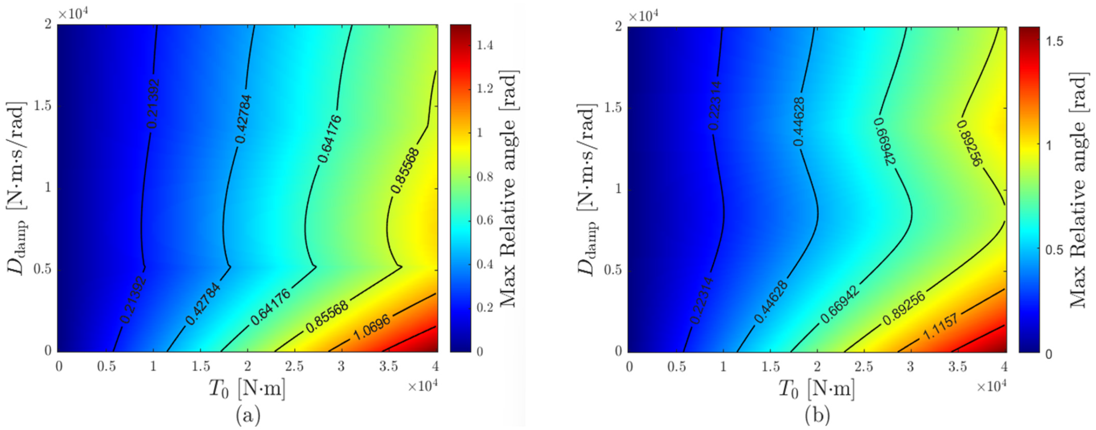
Table 1. Subsequently, the input torque was varied from 0 to 40,000 and the damping coefficient from 0 to 20,000, and the results of calculating the maximum torsional angle are shown in
Figure 8a. The heatmap indicates that the maximum torsional angle is minimized at a damping coefficient of approximately 5200, after which it increases with further coefficient growth and then gradually decreases.
This behavior can be explained by the presence of two pairs of complex conjugate poles in the transient response of the generator speed, each associated with a distinct natural frequency.
Table 2 shows how the variables of Equation (22)—
,
(damping ratios),
,
(natural frequencies), and
,
(magnitudes)—change when the input torque is fixed and the damping coefficient is varied.
As the damping coefficient increases, the two natural frequencies separate, while the magnitudes remain similar. Furthermore, increasing the damping coefficient enhances the damping ratio of the higher-frequency mode while reducing that of the lower-frequency mode.
As seen in
Figure 8, as the damping coefficient increases, the maximum torsional angle decreases, then increases again, and gradually decreases, while at the same time, as in
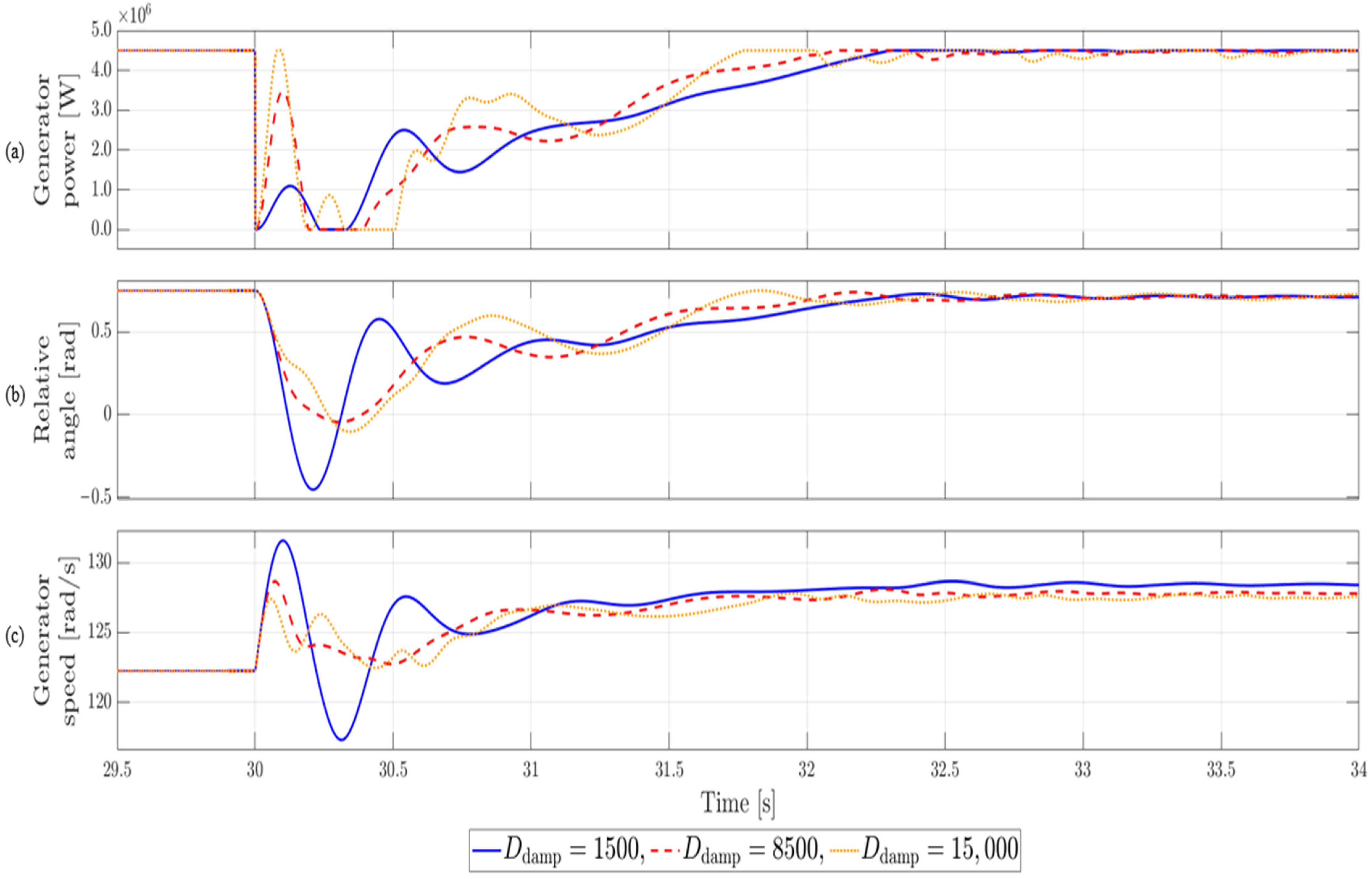
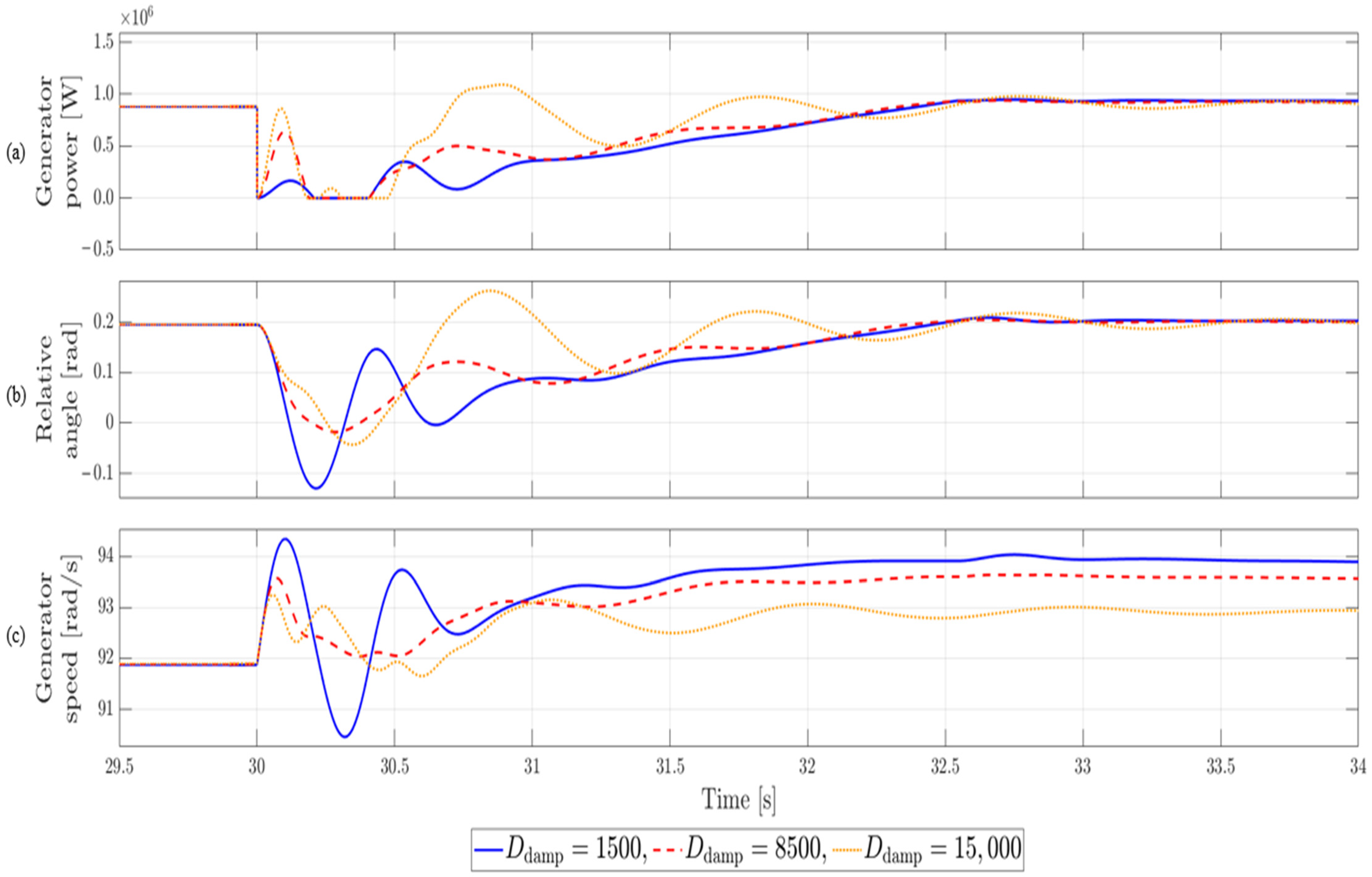
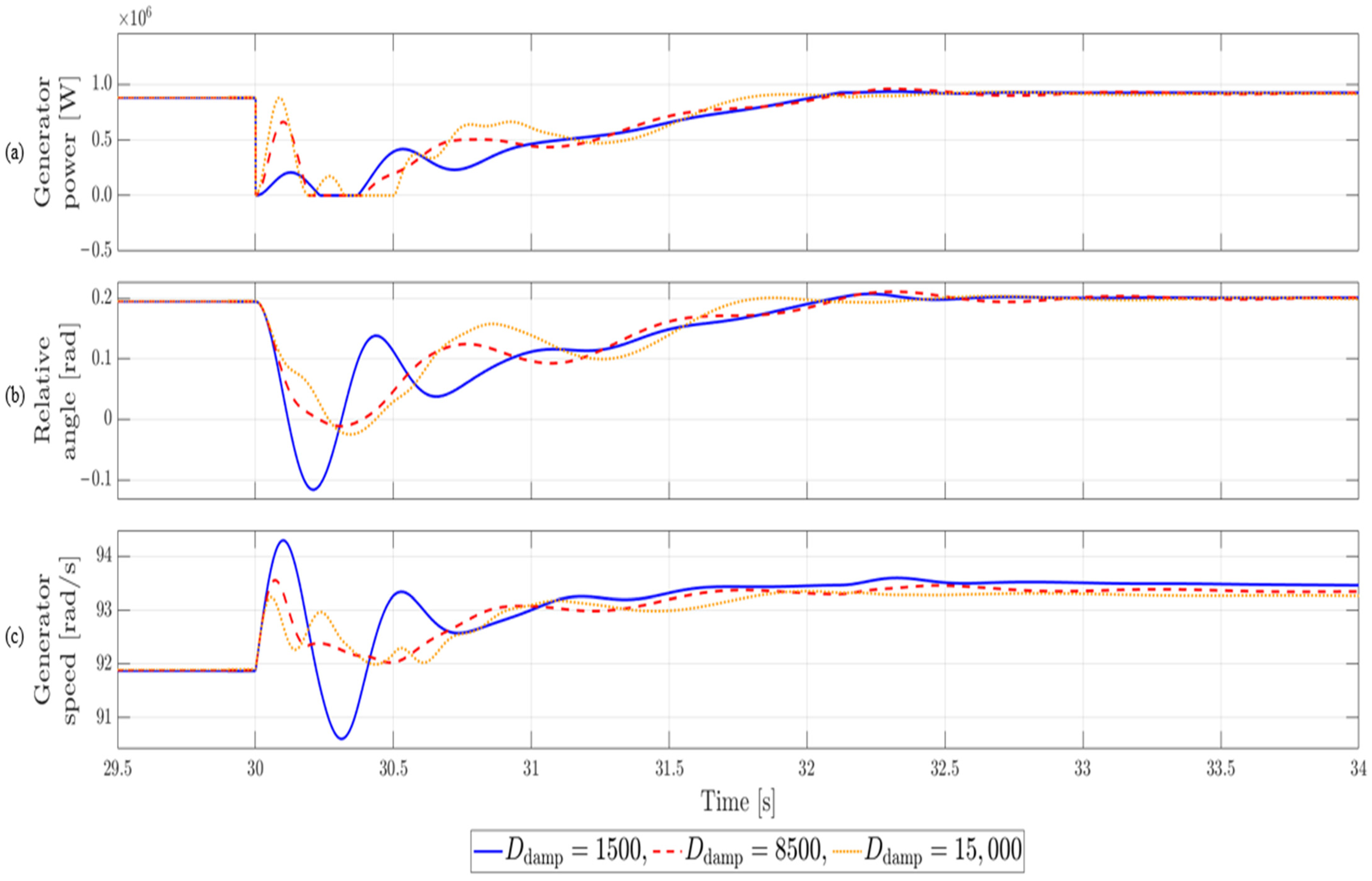
Figure 7, the settling time becomes longer. Therefore, determining an optimal damping coefficient is essential to achieve a balanced trade-off between these two-performance metrics.
Figure 8a illustrates the trend of the maximum shaft torsional angle when the combined generator torque and damping torque,
, is permitted to take negative values. However, in the simulation conditions of this study,
must not become negative, so a constraint was imposed to prevent it from falling below zero. Without zero constraints, a negative
would act in the blade acceleration direction. In addition, under LVRT conditions, it is difficult to deliver or draw power from the grid, and if
becomes negative, DC-link energy is drawn, causing the DC-link to discharge. Therefore, when the constraint is applied,
becomes zero, altering the system dynamics, and the generator speed response and maximum torsional relative angle also change.
That is, if a constraint is imposed to prevent
from falling below zero, the entire time response cannot be represented by a single transfer function, and the solutions must be joined piecewise. When it is above zero, the system operates as a linear closed loop with the transfer function of Equation (17), and when it changes to below zero,
and the system switches to open-loop operation. However, the open-loop equation cannot be applied in isolation; continuity must be enforced at the transition point where
switches sign, ensuring a consistent generator speed response across intervals. Considering these conditions, the input torque was varied from 0 to 40,000 and the damping coefficient from 0 to 20,000. As shown in
Figure 8b, the maximum torsional angle analysis revealed that the optimal damping coefficient was obtained at approximately 8500. When the damping coefficient was set within the range of 1000–2000, the maximum torsional angle was reduced by about 30–37% relative to that condition. Moreover, the same optimal value of 8500 was consistently identified across different output power levels and LVRT durations, demonstrating the robustness of the proposed method with respect to operating point variations. This consistency indicates that the optimal damping coefficient is primarily governed by the mechanical parameters of the system and is relatively insensitive to changes in operational conditions such as generator output or fault duration.
3.4. Proposed Adaptive Damping Implementation
During LVRT events, the generator torque undergoes rapid fluctuations, which significantly excite torsional vibrations within the drivetrain.
To effectively mitigate these oscillations, the optimal damping coefficient suitable for LVRT conditions was determined using the analytical approach introduced in
Section 3.2 and
Section 3.3. As illustrated in
Figure 9, when the LVRT flag is activated, the damping coefficient transitions from its nominal value during normal operation (
) to the LVRT-optimized value (
). To ensure continuity and prevent discontinuities resulting from this abrupt change, the BPF output of the generator speed is multiplied by a ratio
at the rising edge of the LVRT flag.
Once the LVRT condition is cleared, the generator current and torque gradually return to their steady-state operating points. Maintaining a high damping coefficient during this recovery phase can prolong the settling time, adversely affecting dynamic performance. Hence, in accordance with national grid code requirements, the damping coefficient is linearly decreased so that the active power recovery rate satisfies the prescribed time frame, eventually reverting to the nominal range of 1000–2000 commonly used in prior research.
The proposed adaptive damping coefficient is implemented in real time within the outer torque control loop of the generator-side controller. The generator speed signal passes through a band-pass filter (BPF) to isolate the torsional vibration component, which is then multiplied by the variable damping gain to generate the active damping torque (). This compensating torque is added to the generator torque reference and fed into the current control loop.
Because the compensation path is introduced without modifying the existing controller architecture, the proposed scheme can be implemented in real time without requiring additional high-speed processors or external control hardware.
In addition, when the LVRT flag is activated, the transition between and is completed within a single control cycle (on the order of several hundred microseconds), thereby introducing no noticeable delay in the overall control response. Furthermore, since the operating frequency of the proposed algorithm is significantly lower than the sampling rate of the current control loop (several kHz), simulation results confirm that even a delay of 1–2 samples (approximately a few hundred microseconds) does not have a meaningful impact on the torsional damping performance. If the LVRT duration becomes excessively long, the turbine transitions to the shutdown sequence regardless of the damping torque effect. During partial voltage recovery, the damping torque compensation remains active as long as the LVRT flag is asserted and is deactivated only once the LVRT flag is released.

