Abstract
The uneven distribution of airflow on the blade surface of a yaw wind turbine triggers a complex non-constant flow, resulting in turbine flow field operation disorder, which, in turn, affects the structural field. In view of the different degrees of influence of different blade materials on the structural characteristics of a wind turbine, a numerical simulation of the flow field and structural field of the horizontal-axis wind turbine under different yaw conditions is carried out by using the fluid–solid coupling method to quantitatively analyse the degree of influence of the material on the structural characteristics of the wind turbine. The results show that the average velocity of the wake cross-section shows a trend of decreasing, then increasing, and then stabilising at all yaw angles. The larger the yaw angle, the wider is the vortex structure dispersion. As the wake develops downstream, the turbulence intensity is shown to decrease and then increase, and the yaw perturbation exacerbates the turbulence disorder in the wake flow field. Along the wind turbine blade spreading direction, the blade deformation phenomenon is significant. The yaw angle increases, the wind turbine blade deformation increases, and the maximum blade stress first increases and then decreases. At a 15° yaw angle, the airflow on the blade surface is more easily separated, and vortices are formed in the vicinity, which impede the airflow in the boundary layer and lead to a reduction in the velocity in the boundary layer in this region. The minimum deformation and maximum stress of the three materials under a 15° yaw angle indicate that the blades are more capable of resisting external deformation under this condition, so 15° yaw is the best operating condition for the wind turbine. This paper employs different materials to quantitatively analyse the extent to which structural characteristics influence wind turbine performance. The findings from this research can provide valuable insights for optimising wind turbine designs.
1. Introduction
Wind energy, as a clean and non-polluting green energy source, has received attention from many countries around the world. Wind power is one of the most mature forms of power generation in the field of green energy, and in the global power production structure, its proportion shows a rising trend year by year, with the development of broad prospects [1]. The blades of a wind turbine convert wind energy into its own mechanical energy, and the operational performance of the blades directly affects the utilisation of wind energy and the safety of the wind turbine [2]. The blade is inevitably deformed under the action of aerodynamic load, and the structural deformation, in turn, reacts to the flow field, changing the aerodynamic load, which, in turn, affects the structural field again, and the structural field and the flow field are coupled with each other and interact with each other [3]. Large wind turbine blade materials are mostly made of composite materials to ensure their mechanical and fatigue properties [4]. Wind turbines operate in natural wind environments, where the wind direction varies randomly, making wind turbines require yaw systems to face the wind direction, and wind turbines are often operated under yaw conditions [5], where yaw causes an uneven distribution of airflow over the blade surfaces, triggering complex non-stereotypical flows and increasing the fluctuation of aerodynamic loads [6]. The yaw moment will make the tower and nacelle subject to additional alternating loads; the unevenness of the deformation of the three blades changes, which may exacerbate the structural vibration [7]; and fatigue damage is easily triggered by long-term operation, which affects the operational reliability and service life of the wind turbine [8].
In recent years, scholars at home and abroad have carried out research on the characteristics of the flow field and structural field under yawing conditions of wind turbines. In terms of flow field characteristics, the output power of the wind turbine will decrease under yaw conditions [9]; the frequency of wind turbine power fluctuations is about three times the rotational frequency of the wind turbine; the larger the yaw angle, the larger is the amplitude of output power fluctuations [10]; the aerodynamic force to which the blades are subjected decreases; the phenomenon of the separation of the blade flow is enhanced; and the symmetry of the curve of the blade thrust with the change in the azimuth angle disappears gradually [11]. Wind turbine yaw will cause the wake vortex structure to destabilise earlier and increase the turbulence intensity in the far wake region [12]; it will also deflect the wake centre and the turbulent kinetic energy distribution, accelerate the wake velocity deficit recovery, and reduce the downstream interference from wake effects [13,14]. The smaller the dynamic yaw angular velocity, the more time it takes for the wind turbine to align with the wind direction, and the wind turbine is less efficient at utilising the wind energy, thus making the wind energy inefficiently utilised, which results in a larger area of velocity loss in the wake flow field [15]. If the yaw angle of the upstream wind turbine increases, the length of the trailing flow field of the upstream wind turbine will decrease [16], and the downstream wind turbine will move away from the velocity loss region of the trailing flow field, its total wind turbine output power increases, and the thrust force borne by the wind turbine is gradually reduced [17]. Yaw affects the moments applied to the hub by the three blades to a large extent, resulting in a 50% increase in yaw moment [18].
In terms of structural characteristics, the blade deformation law under yaw conditions is quite different from that of axial flow conditions [19,20]. As the yaw angle increases, the dynamic swing deformation has a tendency to increase, the proportion of positive dynamic swing deformation decreases, and the proportion of negative dynamic swing deformation increases [21]. Blade deformation triggers localised stress concentrations, especially at the root of the blade [22]. Continuous exposure of blades to complex stresses during yaw can lead to fatigue damage, and their internal structure can suffer fatigue damage phenomena such as cracks due to repeated stresses [23]. The radial strain values of wind turbine blades for larger yaw angle conditions are often greater than those for smaller yaw angle conditions [24]. The larger the yaw angle is, the more uneven the blade force is, which makes the flow field around the flow field more disturbed, the flow field around the flow field becomes more disordered, and the change in the blade strain is more disordered [25,26]. Due to the effect of the yaw angle, the wind turbine swept area is small, and the rotational speed grows slowly, the wind turbine is mainly subjected to the aerodynamic thrust to produce elastic waving vibration, and with the change in yaw angle, the action of the wind turbine subjected to the aerodynamic thrust is also changed, so the vibration shows up and down fluctuation changes [27]. It has been found that blade deformation decreases the predicted angle of attack, reduces the aerodynamic load distribution [5], weakens the tip vortex strength, slows down the energy exchange in the wake region, reduces turbulence intensity, and delays wake recovery [28,29].
Wind turbine blades should be guaranteed to perform in terms of structural stiffness, ultimate strength, and stability [30,31]. It has been found that the effect of blade material on the characteristics of the wrap-around flow field tends to increase along the radial direction [32] and that the flexible blades of horizontal-axis wind turbines suffer from serious aerodynamic problems under extreme winds, where larger wind load variations increase the aerodynamic damping, which reduces the fluctuations in the tip displacements and root moments of the blades [33]. Composites are highly applicable due to their properties such as high toughness, low density, and extended service life [34]. A material with a higher modulus of elasticity has a higher value of stress in the blade and a higher value of strain in the blade with higher weight [35]. The deformation at the tip position of the leaf blade of solid wood material was greater than that of the blade of epoxy resin material, and the deformation of the leaf blade of solid wood material was greater [36].
In summary, the existence of yaw angle makes the flow field and structure field operation law become more turbulent. Different blade materials produce different deformations in high-speed rotation, the density of the blade material affects the weight of the blade, and the modulus of elasticity affects the degree of deformation of the wind turbine when it is in operation. As a result, the influence of different blade materials on the structural characteristics of wind turbines under yaw conditions is different. This paper adopts the fluid–structure coupling calculation method to quantitatively analyse the influence of different materials on the structural characteristics of wind turbines under yaw conditions. The conclusions of this study can provide a reference for the optimal design of wind turbines.
2. Yaw Leaf Element-Momentum Theory
Leaf element-momentum theory divides the blade into multiple leaf elements, ignores the mutual influence between the leaf elements through the force analysis of each leaf element, and then obtains the force of the whole blade [37]. This paper combines the yaw with the leaf element-momentum theory to establish a yaw wind turbine blade load calculation model. The force analysis of the leaf element of the yaw wind turbine is shown in Figure 1.

Figure 1.
Schematic force analysis of yaw leaf elements.
Under the action of relative incoming wind speed w, the leaf vein will be subjected to aerodynamic force dF; dF is decomposed into dD and dL according to the horizontal and perpendicular directions to the direction of the incoming wind speed and dFa and dFu according to the directions along and perpendicular to the plane of rotation, and dFu is decomposed into dD and dL according to the directions along and perpendicular to the plane of rotation.
The waving force on the leaf vein can be expressed as
In the formula, l is the leaf element chord length; ρ is the air density; ω is the wind turbine rotational speed; r is the rotor radius; Cn is the normal force coefficient; Ct is the tangential force coefficient; Cl and Cd are the lift coefficient and drag coefficient; α is the angle of attack; β is the pitch angle; θ is the mounting angle; γ is the yaw angle; φ is the relative angle of incidence; vdr is the incoming wind speed of the leaf element; and u is the rotational linear velocity of the leaf element.
In order to make the model more relevant to the real situation, according to the vortex theory, and yaw analysis, v and u are corrected, which can be expressed as follows:
where a is the axial induction factor of the wind turbine; b is the circumferential induction factor; rq is the distance from the leaf element to the centre of the hub; vi is the incoming wind speed of the leaf element; and ω is the rotational speed of the wind turbine.
3. Numerical Simulation
3.1. Wind Turbine Model
In this paper, a three-bladed horizontal-axis wind turbine of S-wing type is selected as the research object, and Table 1 shows the design parameters of the wind turbine.

Table 1.
Wind turbine design parameters.
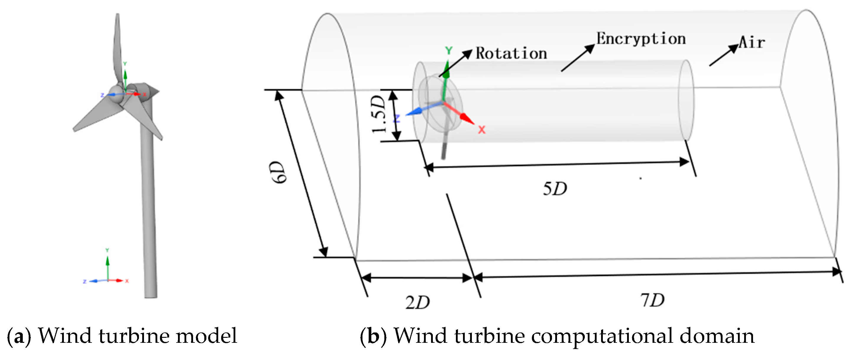
The 3D structural model of the wind turbine was established using a 3D shell structural model, which has structural parameters close to the real physical model [13]. The wind turbine is modelled 1:1 using 3D modelling software (SolidWorks), as shown in Figure 2a. The computational domain is constructed using modelling software as shown in Figure 2b. The rotation domain and the encryption domain are connected via an interface. We define the hub centre for designing the wind turbine as the coordinate origin O, with the Z-axis in the opposite direction to the airflow wind direction and the Y-axis upwards vertically.
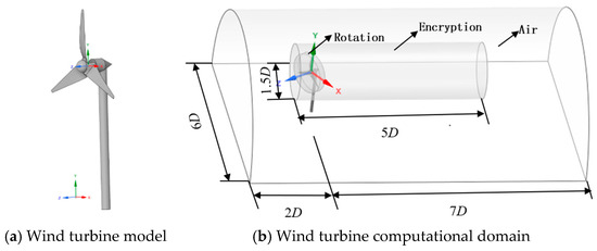
Figure 2.
Wind turbine and computational domain model.
Based on reference [32], it is evident that altering the blade material significantly impacts the structural field. Consequently, the characteristic parameters of the three wind turbine blade materials selected in this paper are shown in Table 2.

Table 2.
Parameters of blade material properties.
3.2. Grid Division
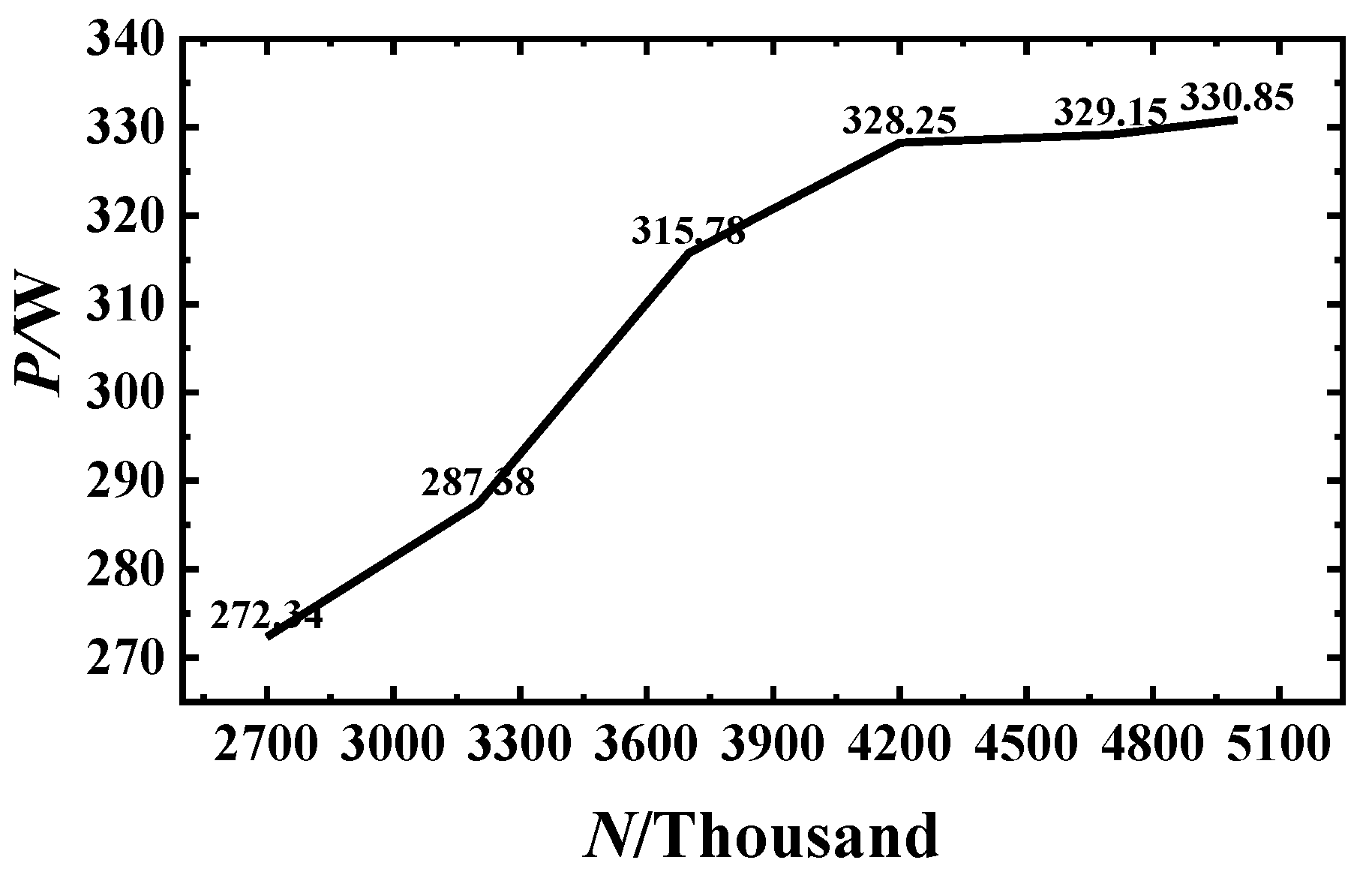
This study employs the Mesh module in ANSYS Workbench to generate tetrahedral and hexahedral meshes for both the flow field and structural domain. Under axial flow conditions, unsteady calculations of the rotor output power were performed using meshes with varying numbers of elements. The results are shown in Figure 3, where N represents the number of mesh elements and P denotes the power output. As shown in Figure 3, when the flow field mesh count reaches 4.2 million, the output power exhibits stable variation with increasing mesh count. The final mesh configuration was determined to be approximately 4.2 million cells for the flow field and 400,000 cells for the structural field, achieving a favourable trade-off in CPU time. Specifically, the blade body mesh has an edge length of 5 mm, while the hub and rotating shaft mesh feature an edge length of 10 mm. The feature clearance dimension is set to 3 mm. The average element quality of the structural mesh is 0.857 > 0.8, meeting the mesh quality requirement standard. The mesh size for the rotating domain is 10 mm, with a contact dimension of 19.5 mm. The refined domain features a mesh size of 50 mm, while the air domain uses a 100 mm mesh size. The curvature capture function is enabled in the boundary layer and rotating domain regions to more accurately describe geometric details, thereby enhancing simulation precision and reliability.
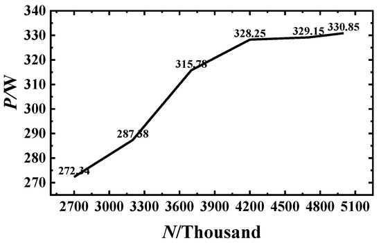
Figure 3.
Verification of grid independence.
3.3. Simulations
In this paper, numerical simulation software is used to calculate the unidirectional fluid–structure coupling of the wind turbine. The k-ε turbulence model with good generality is used in the calculation, 1° rotation of the wind turbine is taken as a time step for the simulation, and the fluid–structure coupling surfaces are the surfaces of the three blades of the wind turbine. The computational domain employs a velocity inlet with uniform wind speed and a pressure outlet. The wind turbine’s rotational axis direction vector is set to (1, 0, 0). The inlet turbulence intensity is set to 5%, and the walls are modelled as free-slip surfaces to eliminate the influence of wall shear stress on the turbine’s flow field.
During transient calculations, the calculations are considered to converge when the residuals of the velocity component of the momentum equation are less than 10−6 and the residuals of the turbulent kinetic energy dissipation rate ε turbulent kinetic energy k in the continuity equation are reduced to less than 10−4 [38].
3.4. Numerical Computation Method Validation
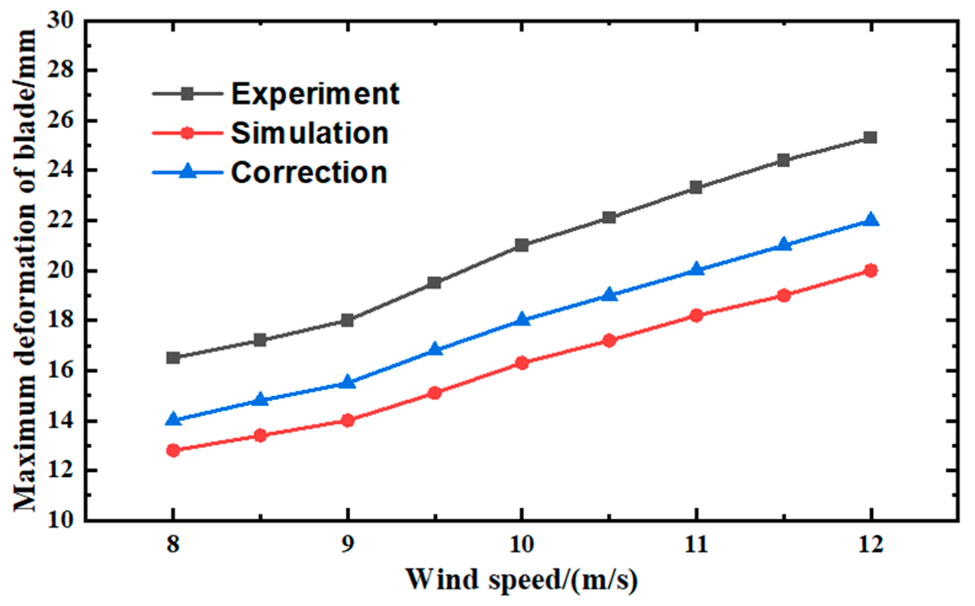
In order to verify the validity of the calculation results, the blade material of the numerical simulation prototype is the same as the experimental wind turbine, which is the same as the experiment in the literature [5] (experimental data in the figure), and the verification calculations are carried out. The solid wood wind turbine blade tip waving deformations at different wind speeds were compared with the experimental values. The results are shown in Figure 4. The tip displacements, equivalent stresses, and equivalent elastic strains of the blade under uniform incoming flow were calculated using the established equivalent model, which were in good agreement with the results calculated in the literature [32], verifying the feasibility of the model for calculations in fluid–structure coupling.
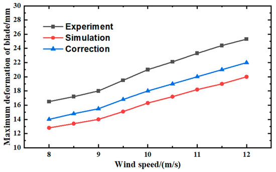
Figure 4.
Comparison of maximum blade deformation.
In the literature [20], due to the existence of wind turbine prototype base and foundation fixed instability, blade vibration, caused by vibration deformation of the unit to produce a large amount of vibration deformation, making the experimental measured deformation larger, and the numerical calculation of the above factors are ideal; there is no vibration deformation, so the calculated value is lower than the experimental value, but the two changes in the trend are consistent with the experimental analysis of the removal of vibration deformation of the error generated by the data, and it can be seen that the two are in line with each other. In order to further verify the correctness, the material 1 blade deformation under axial flow conditions is also compared with the simulation results from the literature [16], and the error is 5.96%, which is within the error range; therefore, the results of this calculation are considered valid.
4. Analysis of Calculation Results
4.1. Flow Field Characterisation
In this paper, three key parameters, axial velocity, vorticity, and turbulence intensity, are analysed in the wind turbine wake flow field at different yaw.
4.1.1. Analysis of Speed Characteristics
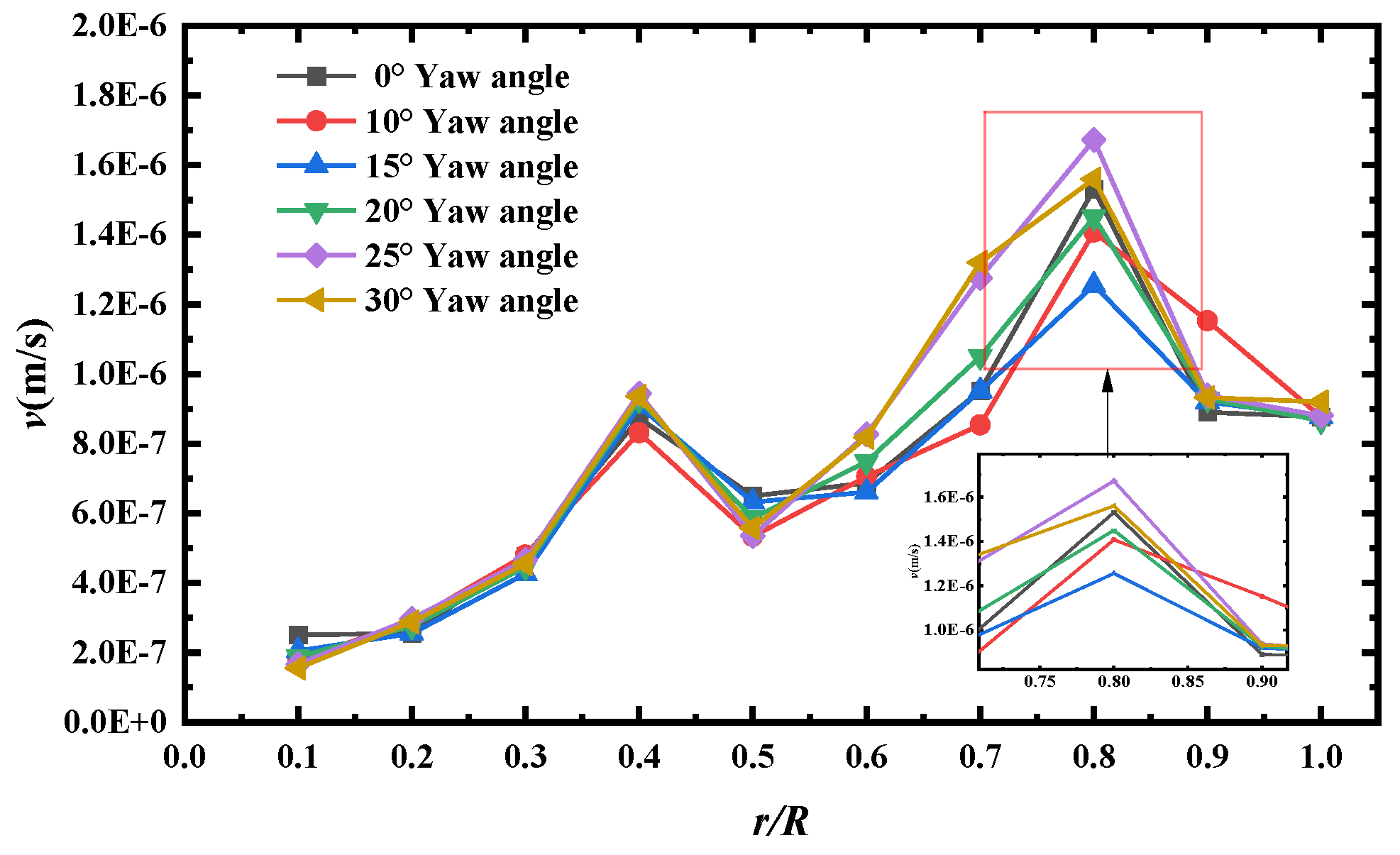
When the air flows over the surface of the blade, due to the viscous fluid, the air velocity close to the surface of the blade is approximately 0; as the distance from the surface of the blade increases, the air is less affected by the viscosity, and the velocity is gradually close to the external mainstream wind speed. This velocity from 0 gradually transitions to the mainstream speed of the thin region, which is the boundary layer. The fluid flow within the boundary layer is called the boundary layer velocity. A boundary layer velocity distribution affect, among other things, is airflow separation. This changes the operational efficiency of the wind turbine and the aerodynamic state of the blades. Figure 5 shows the boundary layer velocity curve of the blade along the direction of leaf spread under different yaw conditions. The figure shows the variation in boundary layer velocity along the blade spreading direction under different yaw angles of the wind turbine. The horizontal coordinate r/R indicates the relative distance of the boundary layer from the blade root, and the vertical coordinate v indicates the average velocity at the boundary layer.
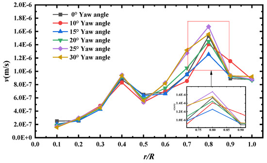
Figure 5.
Velocity profiles in the boundary layer along the blade spreading direction.
From the figure, which shows the wind turbine blade under different yaw conditions, along the direction of leaf spread, the average velocity at the boundary layer shows an overall trend of first increasing and then decreasing. When r/R goes from 0 to 0.8, the average velocity at the boundary layer increases gradually as r/R increases. Because the blade root is connected to the hub, the boundary layer is easily disturbed by the blade root structure, the airflow velocity is limited, and the velocity is low. Moving towards the middle of the leaf, the chord length decreases, and the region is less constrained by the leaf root structure, the airflow acceleration effect is gradually manifested, and the velocity continues to climb to the peak, with the smallest peak value at 15° yaw angle and the largest peak value at 25° yaw angle. When r/R goes from 0.8 to 1, the velocity reaches the peak and then starts to decrease. It is analysed that, when approaching the tip of the blade, the tip vortex of the blade is enhanced, and the flow phenomena, such as separation and vortex, occur in the tip region of the blade, which leads to an increase in the energy dissipation in the boundary layer, making it difficult to maintain the peak state of the average velocity in the boundary layer, and a fall back occurs. Operating under different yaw conditions, the trend of the velocity curves is similar, but there are differences in the values. It is analysed that the yaw causes the airflow incidence conditions to change, which makes the velocity values and peak sizes and positions in each spreading position different. At 15° yaw angle, it may make the airflow angle of attack at the 0.8 position of the blade spreading direction in a specific range, resulting in easier airflow separation. When airflow separation occurs, complex flow patterns such as vortices can form near the blade surface, impeding the airflow within the boundary layer and causing the boundary layer velocity to decrease at that location.
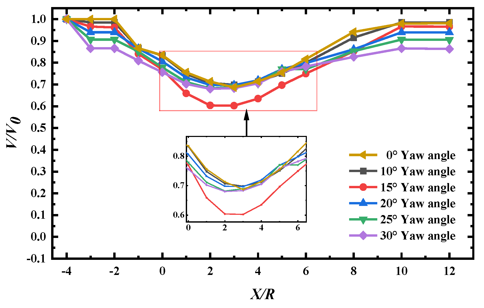
Figure 6 shows the variation in the mean axial velocity of the wake section of the wind turbine under different yaw conditions. The horizontal coordinate represents the ratio of the distance X from the trailing flow field cross-section to the centre of the wind turbine to the diameter D of the wind turbine, and the vertical coordinate represents the ratio of the average velocity V of the trailing flow field cross-section to the incoming wind speed V0.
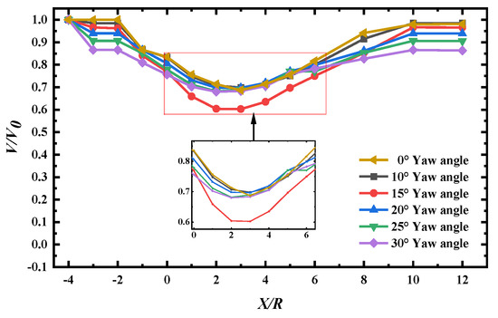
Figure 6.
Mean velocity cross-section of different sections of the blade under yaw condition.
From the figure, it can be seen that, with the increase in the distance from the wake cross-section to the wind turbine slewing centre, the average velocity of the cross-section under each yaw angle shows a trend of decreasing, then rapidly increasing, and then gradually smoothing out. The axial velocity recovers faster in the range of 0.5D~1D after the wind turbine, and it can recover to more than 70% of the incoming flow. In the stage of 2D~5D, the velocity grows faster; at 5D, the velocities are all recovered to more than 85% of the incoming flow velocity, and the curves of different yaw angles gradually approach. The larger the yaw angle, the more pronounced the wind turbine deflection is, and thus, the more the velocity of the wake field is reduced, and in the near wake flow field, the airflow velocity will be close to the incoming flow velocity. The wake recovery is faster when the yaw angle is smaller and slower when the yaw angle is larger.
It can be analysed that, when X/D is small, the wind turbine rotation does work on the airflow, the blade wake has a strong effect of coiling suction and doping, and the kinetic energy loss of the airflow is large, resulting in a low axial cross-section average velocity. With the downstream development of the wake, the surrounding airflow is constantly supplemented to the wake region, the wake and the airflow are constantly exchanging momentum, the kinetic energy is gradually restored, and the average velocity of the cross-section rises. When the momentum exchange tends to stabilise, the axial mean velocity tends to level off. When the wind turbine yaws, the deflection effect of the blades on the airflow leads to a decrease in the airflow velocity in the region close to the wind wheel. When the yaw angle is larger, the wind turbine’s blocking and deflecting effect on the air stream is more obvious, and more energy is extracted from the air stream, which results in a large initial disturbance and kinetic energy loss of the wake and reduces the recovery speed of the wake. The content is in line with the conclusions in the literature [30]. It can be seen in the figure that the cross-section average velocity of the bypass flow field at 15° yaw angle is the smallest, but the velocity recovery is the fastest in the wake flow field, which is favourable to the operation of the downstream wind turbine.
4.1.2. Eddy Volume Analysis
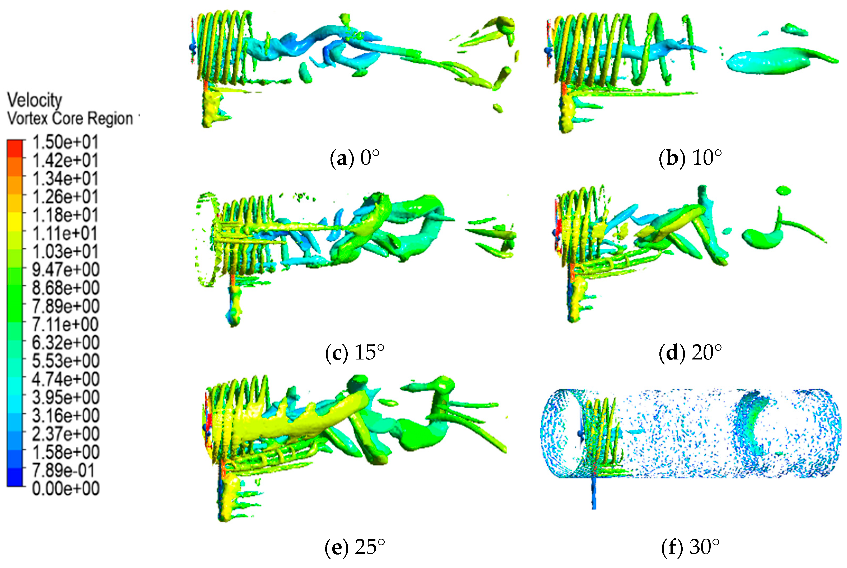
Figure 7 shows the vortex intensity diagram obtained for the wind turbine at different yaw angles. The wake region of the wind turbine consists of tip vortices formed by rotating blade tips and a continuous radial tubular vortex surface as well as a central vortex centred on the hub [33].
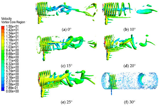
Figure 7.
Vorticity maps at different yaw angles.
From the vortex diagram, it can be seen that, when there is no yaw, the vortex structure is relatively regular and concentrated, the wind turbine impedes the incoming flow uniformly, and the wake vortex develops along the symmetric path because the axis of the wind turbine is the same as the direction of the incoming flow, and when the air flow passes through the wind turbine, the force on each part of the blades and the flow state are relatively symmetric, and the pattern of vortex generation and shedding is stable. When the yaw is 10°~20°, the vortex structure becomes dispersed and turbulent, and the wake flow field begins to shift, the separation of the airflow in some areas is advanced, the interaction between the wake and the shedding vortex increases, the degree of mixing increases, and the turbulence of the vortex pattern in the near wake area rises. When the yaw is 25°~30°, the vortex structure is more broken, the dispersion range is wide, and the wake deflection is significant. The spatial distribution of wind turbine obstruction to the incoming flow is extremely uneven, the stall region is extended, a large number of separated vortices are generated and interfere strongly with each other, the wake is doped in a wider range, and the influence of the vortex structure can be seen in the far wake region. The content is in accordance with the conclusions in the literature [39].
4.1.3. Turbulence Intensity Analysis
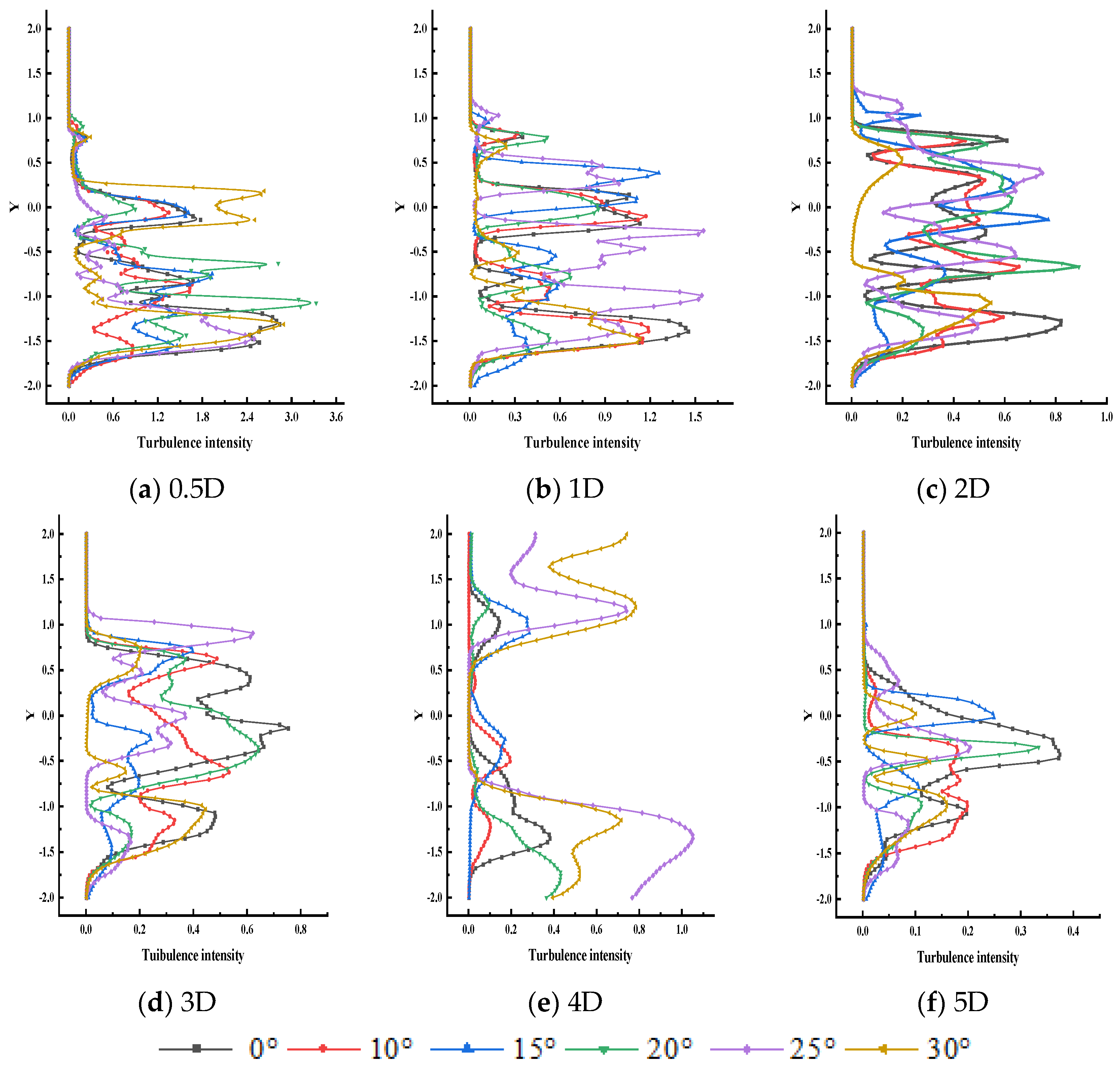
When a wind turbine operates, the blades do work on the airflow, resulting in momentum loss and turbulence generation in the wake region. In wind farms, turbulence intensity is related to wind turbine blade loading and fatigue loss. Excessive turbulence intensity will make the blades subject to frequent and large aerodynamic load fluctuations, accelerating component wear and shortening the operating life of the turbine. Analysing the change rule of turbulence intensity in the flow field under yaw operation is crucial for the safe operation of wind turbines. Figure 8 shows the distribution of turbulence intensity in the wake flow field of a yawing wind turbine.
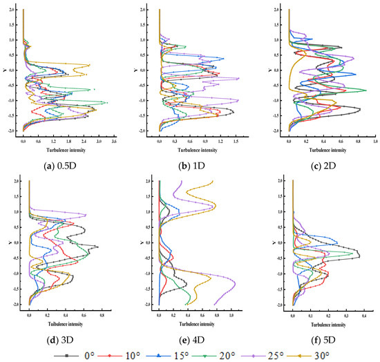
Figure 8.
Intensity of turbulence in different sections of the wake flow.
As can be seen from the figure, with the increase in the cross-section of the wake flow field, the turbulent kinetic energy shows the change rule of decreasing and then increasing. At the 0.5D section of the wake flow, the peak turbulence intensity is high and fluctuates violently; at the 5D section, the peak turbulence intensity rises, and the fluctuation of the curve tends to flatten. The reason for this is that, at the 0.5D section near the wind turbine, the wake is strongly affected by blade rotation and aerodynamic interference, and the turbulence intensity is high and complex; as the wake develops downstream, the airflow mixes with the surrounding environment, the momentum is gradually restored, and the turbulence is attenuated due to energy dissipation. Under different yaw conditions, the turbulence intensity changes in different trends. When the yaw angle increases, the turbulence intensity decay process is more complicated, the curve fluctuation is more frequent, and the turbulence evolution of the wake flow field is more irregular after the yaw interference. In the 0.5D cross-section, the wake that is affected by the external doping is small, mainly disturbed by the force acting with the wind turbine, and the difference in the flow field is enhanced in different yawing conditions; in the 5D cross-section, the long-time and long-distance doping causes the wake energy to be dissipated greatly, and the turbulence intensity curves corresponding to the yaw angles tend to be close to each other. The turbulence intensity curves for each yaw angle tend to be close to each other. Fluid bypassing the wind turbine in different wake cross-sections produces different rules of change due to the existence of the yaw angle makes the turbulence intensity become more turbulent, and the turbulent flow field will have an impact on the structural field.
The above analysis of the flow field characteristics of the wind turbine under different yaw conditions shows that, at 15° yaw, the airflow is more prone to separation, which will form vortices and other complex flow patterns near the blade surface, hindering the airflow in the boundary layer and making the velocity of the boundary layer at this location decrease. The cross-section average velocity of the winding flow field at 15° yaw angle is the smallest, and the velocity recovery is the fastest in the wake flow field, which is favourable to the operation of the downstream wind turbine.
4.2. Analysis of Structural Characteristics
4.2.1. Blade Deformation Analysis
Analysis of Blade Spreading Deformation of Different Materials Under Yaw Condition
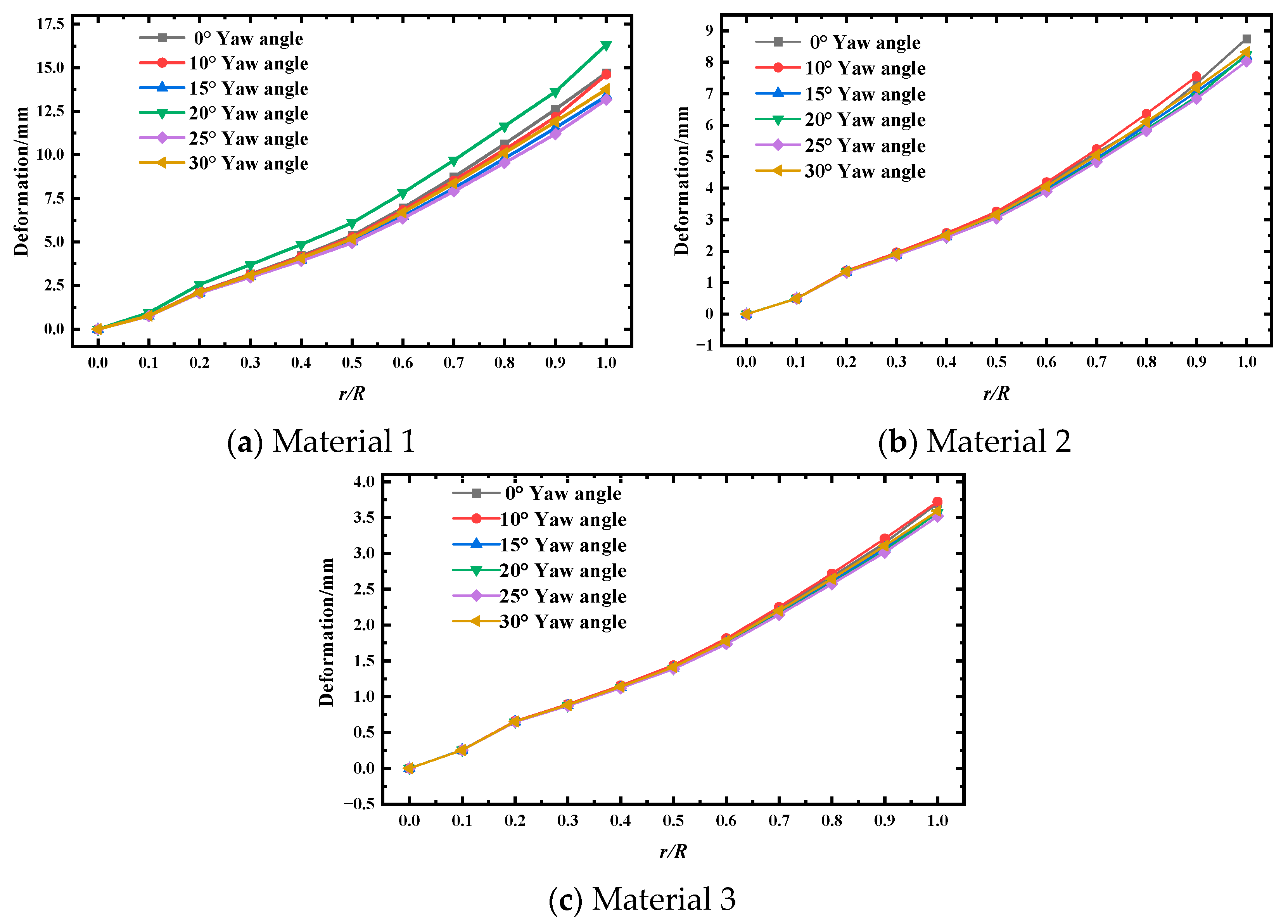
There is irregular deformation of the three blades with increasing yaw angle; the most obvious deformation of one blade is selected to explore the deformation of wind turbine blades with a fixed yaw angle (0°, 10°, 15°, 20°, 25°, 30°) by changing the blade material, and the blade deformation results are obtained.
In this paper, the effect of gravity on blade displacement is not considered; therefore, the blade deformation generated by the effect of aerodynamic loads is mainly considered in wind turbine operation, the blade linear velocity gradually increases along the blade spreading direction, and the aerodynamic force at the tip of the blade is relatively larger, resulting in a larger amount of deformation. Close to the position of the blade root, the change in yaw angle has a relatively small effect on the amount of blade deformation along the spreading direction. This is mainly due to the fact that the blade root is fixed, and the resulting binding force from the blade root to the tip gradually decreases. However, with the increase in r/R, the influence of the change in yaw angle on the spanwise deformation of the blade is gradually significant.
As the yaw angle increases, the wind turbine blade is subjected to more unstable airflow and complex loads, which increases the deformation of the blade at all positions in the spreading direction. The modulus of elasticity of material 1 is small, and its ability to resist elastic deformation is weak. Under the same yaw load, its spreading deformation is relatively larger than that of material 2, which has a larger modulus of elasticity. Material 3 has the largest modulus of elasticity, which indicates that it has the best toughness, and when subjected to yaw-induced load impact, it will alleviate the increase in deformation to a certain extent, and its deformation with the yaw angle of the change curve is relatively smooth (Figure 9).
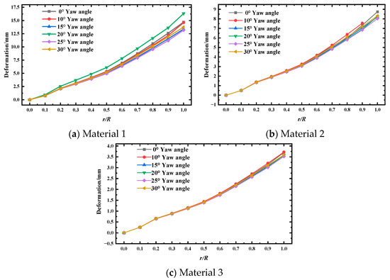
Figure 9.
Blade spanwise deformation.
Analysis of the Maximum Deformation of Blades Made of Different Materials Under Yaw Conditions
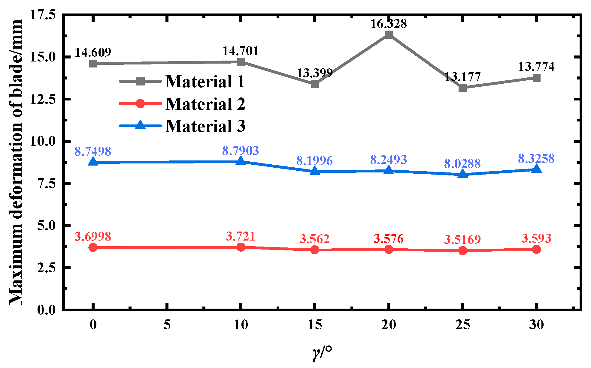
The change in yaw angle causes the aerodynamic loads imposed on the blades by the incoming wind to have a component along the blade spreading direction, and the axial thrust acting on the blades is reduced. Aerodynamic changes affect different materials to different degrees. As the yaw angle increases, the tendency to increase the component of aerodynamic load along the blade spread is also greater, so that the axial thrust acting on the blade decreases with increasing wind speed. At the same time, the existence of yaw angle also has an effect on the centrifugal load, resulting in differences in the increase in deformation at different yaw conditions [20]. Figure 10 shows different materials for a wind turbine with yaw angle increase blade maximum deformation law change distribution.
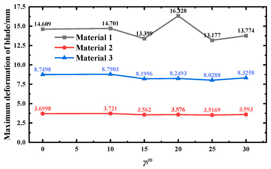
Figure 10.
Maximum deformation of leaf tip.
Under different yaw conditions, the tip deformation of material 1 blade is basically stable at about 13~15 mm, the tip deformation of material 2 blade is basically stable at about 8~9 mm, and the tip deformation of material 3 blade is basically stable at about 3~4 mm. The yaw angle increases from 15° to 20°, and the maximum deformation growth rate of material 1, 2, and 3 blade is 21.85%, 0.61%, and 0.38%, respectively. Material 3 has a high modulus of elasticity and good mechanical stability, which can effectively resist the aerodynamic changes caused by the change in yaw angle, so that the deformation is relatively stable. Among them, material 1 has the most obvious growth, and the analysis of the reasons can be seen: the low elastic modulus of material 1 makes it easier to deform when subjected to force. At 20° yaw angle, the aerodynamic force change resonates with the intrinsic frequency or mechanically sensitive direction of material 1 or a special coupling effect, resulting in a sharp increase in deformation. The yaw angle increases from 20° to 25°, and the maximum deformation decrease rates of material 1, 2, and 3 blades are 19.29%, 2.67%, and 1.64%, respectively. It is analysed that, when the yaw angle is 25°, the angle between the impeller centre plane and the incoming wind direction increases, and the impact of the air fluid on the wind wheel is weakened, which in turn reduces the axial thrust and aerodynamic force, thus reducing the blade deformation. Yaw angle from 25° to 30°, the deformation back up. Analysis of the reasons can be seen: yaw angle is too large; the air flow around the impeller forms a more complex three-dimensional flow field; and the blade, due to local airflow separation or turbulence intensity increases, is subjected to an abnormal load, resulting in the deformation of the amount of rebound. When the yaw angle exceeds the ‘rigid support’ range of centrifugal force, aerodynamic force dominates the deformation, especially at the tip of the blade, the centrifugal force increases with the radius, but the aerodynamic force is more significant, and the deformation may rebound.
4.2.2. Blade Stress Analysis
Stress is a physical quantity that describes the internal force state of wind turbine blades, which is the force generated by the interaction inside the blades when the wind turbine is subjected to wind loads [40]. The characteristics of stress include resisting deformation and transmitting internal forces, and excessive stress may also lead to hazards such as blade cracking and deformation, so it is crucial to explore the changing law of stress.
Firstly, from the blade stress cloud map, the stress distribution law of the three blade materials wind turbine under a no-yaw working condition is qualitatively analysed, and the stress cloud map of the blade pressure surface is mainly studied [41] because the stress on the pressure surface of the wind turbine blade is larger than that on the suction surface, and there exists a stress concentration area. Then, the maximum stress values of the three blade materials under different yaw conditions are extracted for analytical study, which quantitatively reveals the change trend of blade stress.
Blade Surface Stress Cloud Analysis
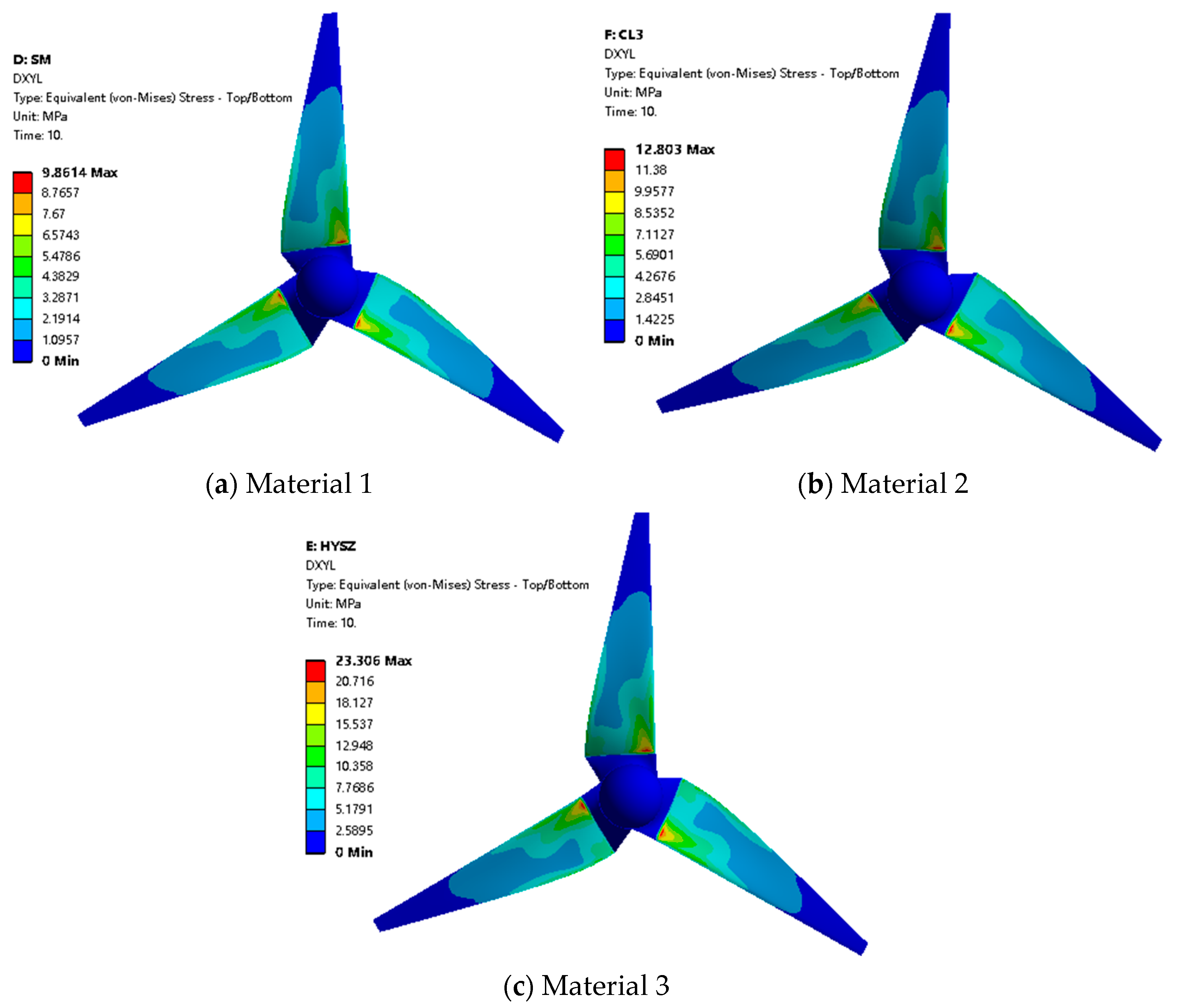
Extracted wind turbine stress cloud diagrams of the wind turbine with different material blades under rated uniform incoming wind speed and rated tip speed ratio conditions are shown in Figure 11.
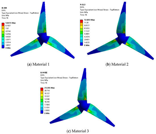
Figure 11.
Stresses in wind turbine with different material blades.
As can be seen in Figure 11, the stress is uniformly distributed on the three materials blades; there is a stress concentration range at the maximum chord length of the blade and the middle of the blade close to the leading edge; the stress at the leaf root of the blade corresponding to material 1, material 2, and material 3 is the largest, which is 9.86 MPa, 12.80 MPa, and 23.31 MPa, respectively; and it can be seen that the strongest resistance to deformation is found at the root of the blade, which is in agreement with the deformation of the leaf tip proposed above The large change rule is consistent.
Analysis of Maximum Stress on Blade Surface
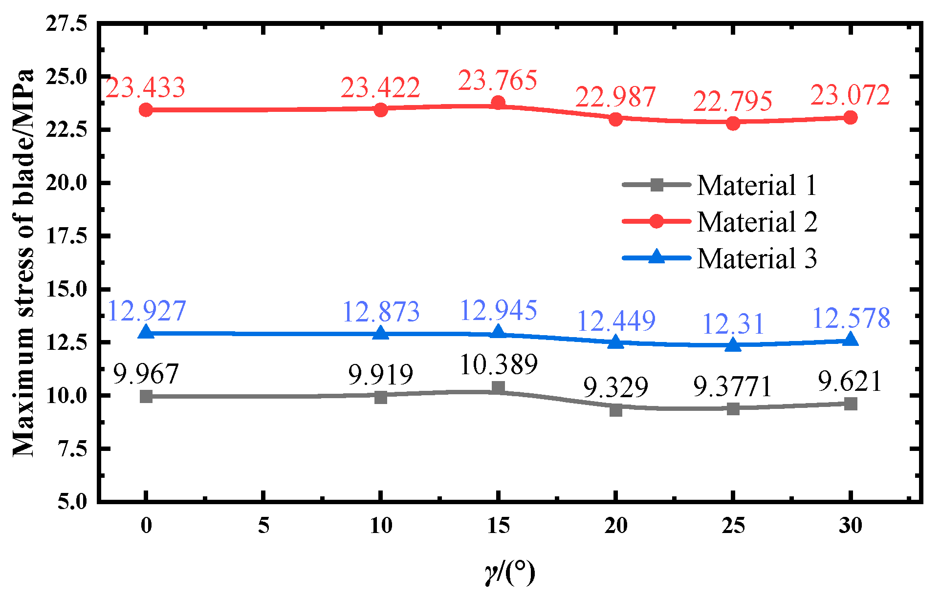
In order to investigate the change rule of blade stress of different materials, the maximum stress value of the blade root of three materials is selected under different yaw conditions, as shown in Figure 12.
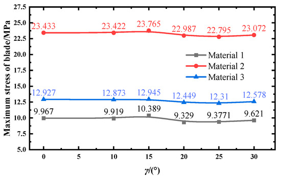
Figure 12.
Maximum stress on blade surface of different materials.
The results show that the trends of the maximum stress values of the blade root of the three materials are basically the same. With the increase in yaw angle, the overall trend of the maximum stress value of the blade shows a slight increase and then a decrease. Yaw has a relatively minor effect on the maximum stress values of wind turbine blades.
The blades of different materials have different mechanical properties, such as their own modulus of elasticity and strength. Materials 1, 2, and 3, due to the differences in their own properties, have different degrees of stress response under the aerodynamic force caused by the same yaw angle change. The maximum stress values shown in Figure 7 all appeared at the position of a yaw angle of 15°.
The yaw angle increases from 0° to 15°, and the stress values are more stable with a slight increase. The yaw angle increases from 15° to 25°, and the stress value decreases. The maximum stress values of material 1, 2, and 3 blades decreased at 9.74%, 4.91%, and 4.08%, respectively. It is analysed that, when the yaw angle continues to increase, the airflow around the surface of the blade changes, generating phenomena such as flow separation, which makes the aerodynamic force decrease. When the blade rotates, it is subject to centrifugal force and aerodynamic force, the coupling relationship between these two forces changes, and their component forces in certain directions cancel each other or weaken, resulting in a reduction in the combined force on the blade and a decrease in the maximum stress value. When the yaw angle increases from 25° to 30°, which is a small increase, material 1, 2, and 3 blade maximum stress value growth rates are 2.61%, 2.26%, and 1.22%. Analysis of the reasons can be seen: yaw angle is too large; the path of airflow around the blade changes, so that the original separation of the airflow gradually re-attaches or form a new pressure distribution; there is an increase in the value of pressure difference on the blade surface, there is an increase in aerodynamic forces, and there is an increase in the value of maximum stress on the blade.
4.2.3. Blade Equivalent Elastic Strain Analysis
Stress is the cause of strain, and strain is the result of stress. According to Hooke’s law, the relationship between stress and strain is expressed as
where σ denotes stress, ε denotes strain, and E is the modulus of elasticity.
σ = Eε
Blade Surface Elastic Strain Cloud Analysis
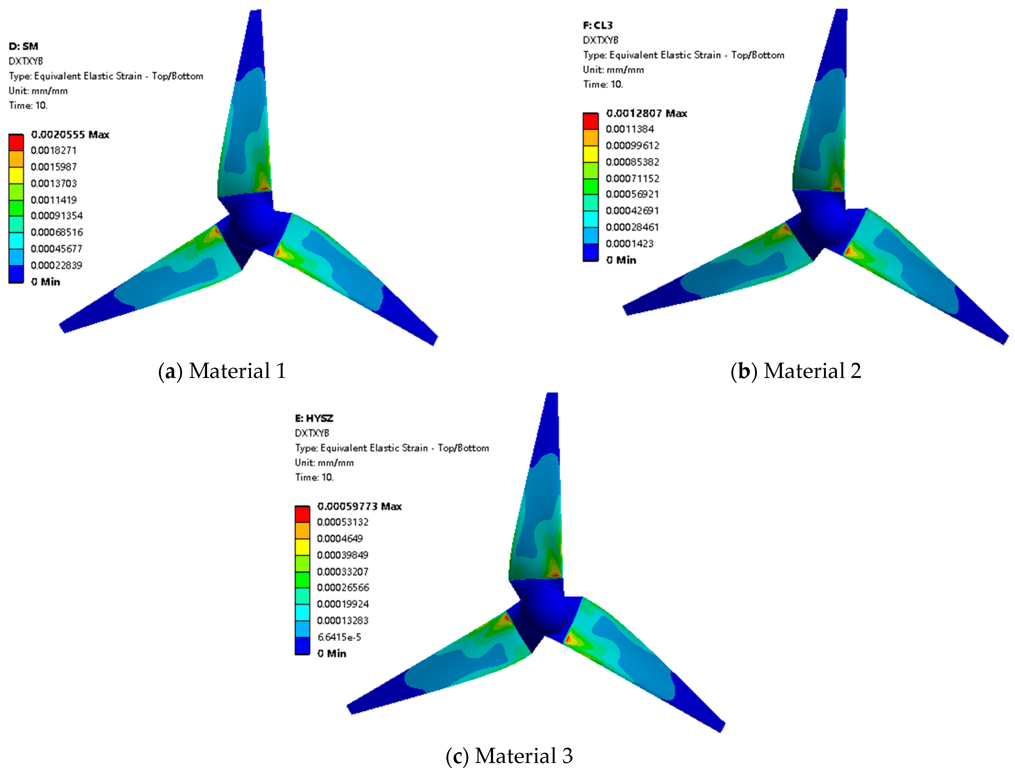
The elastic strain cloud diagrams of wind turbine with different materials blade wind turbine under rated uniform incoming wind speed and rated tip speed ratio working conditions are extracted, as shown in Figure 13.
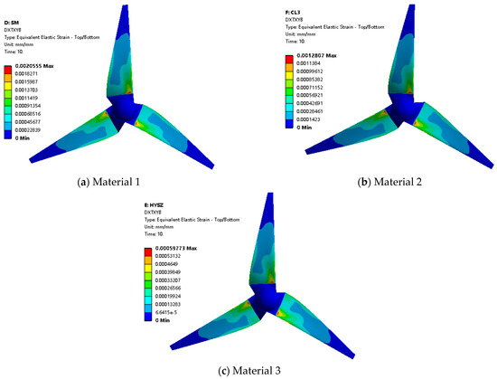
Figure 13.
Elastic strain of wind turbine with different material blades.
Analysing the cloud diagrams, it can be seen that material 1, material 2, and material 3 correspond to the largest elastic strains at the blade root, which are 2.06 × 10⁻³, 1.28 × 10⁻³, and 5.98 × 10⁻⁴, respectively. In view of the homogeneous nature of the blade materials, the equivalent strain cloud diagrams and the equivalent stress cloud diagrams show a corresponding relationship, and they are mainly concentrated in the region of r/R = 0.2 to 0.7 [42,43].
Maximum Elastic Strain Analysis of Blade Surface
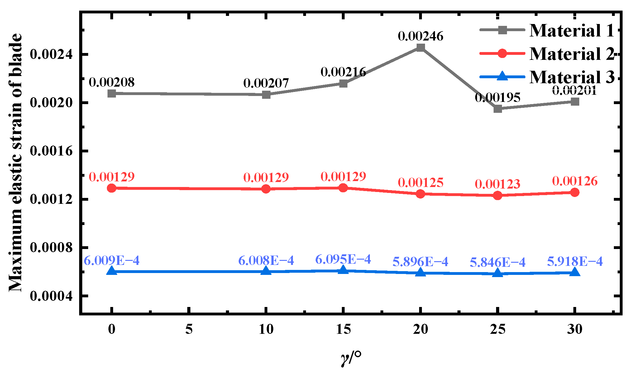
In order to investigate the equivalent strain distribution law of different material blades, the maximum elastic strain values of leaf roots of three material blades under different yaw conditions are selected, as shown in Figure 14.
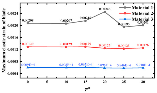
Figure 14.
Maximum elastic strain at the blade surface for different materials.
The mechanical property parameters, such as modulus of elasticity and Poisson’s ratio, of material 1 are more sensitive to the change in angle, which leads to a large change in internal stress–strain response when the yaw angle is changed, while the mechanical properties of material 2 and material 3 are relatively stable, which are better toughness materials and can better adapt to the change in direction of the external force, and are less affected by the yaw angle. The yaw angle increases from 20° to 25°, and the elastic strain values all decrease. The maximum elastic strain values of material 1, 2, and 3 blades decreased by 20.44%, 1.12%, and 0.84%, respectively. The analysis of the reasons can be seen: for the wind turbine blade made of Material 1, increasing the yaw angle from 10° to 20° causes the mechanical coupling effect of wind loads to gradually accumulate stress in the blade, leading to rising strain. At 20°, a critical load state is reached, resulting in a peak strain value. The mechanical properties of the other materials exhibit low sensitivity to yaw angle changes, maintaining stable strain levels. At 25°, for a wind turbine, the angle of incidence of the air fluid changes; thus, the aerodynamic loads on the wind turbine are unevenly distributed, and the force of the air fluid on the blades is weakened, resulting in a reduction in the combined force on the blades. The airflow excitation frequency may be far away from the blade’s intrinsic frequency, avoiding the resonance phenomenon, and then, the maximum elastic strain value is reduced.
From the above analysis of the structural characteristics of the three materials of wind turbine blades under different yaw conditions, it can be seen that, in the yaw 15°, the three materials wind turbine blade deformation is the smallest, and the stress is the largest; it can be seen that the wind turbine blade resistance to the outside world deformation ability is strong in this condition, in terms of power generation efficiency. Wind turbines perform best under no-yaw conditions. However, in actual operation, wind turbines typically run under yaw conditions; it can be seen that yaw 15° condition is the best operating conditions of the wind turbine.
5. Conclusions
This paper adopts the method of combining numerical simulation and theoretical analysis of fluid–solid coupling to study the variation rule of structural characteristics of a wind turbine under yaw condition by different blade materials and draws the following main conclusions:
- Along the direction of the leaf spread, the average velocity at the blade boundary layer first increases and then decreases, and the average velocity of the wake cross-section under each yaw angle first decreases, then rises, and then gradually stabilizes. The larger the yaw angle is, the more obvious the deflection effect is, and the more the airflow velocity decreases. When the wind turbine yaws, the vortex structure disperses in a wide range, and the wake deflection is significant. The spatial distribution of the wind turbine’s obstruction to the incoming flow is extremely uneven, the stall region expands, and a large number of separating vortices are generated and interfere strongly with each other. As the wake develops downstream, the turbulence intensity first decreases and then increases. When the yaw angle increases, the turbulence intensity decay process is more complicated, and the turbulence evolution of the wake flow field is more turbulent after yaw interference.
- Along the wind turbine blade spreading direction, the blade deformation phenomenon is gradually obvious. The yaw angle is too large, and the blade deformation increases. With the increase in yaw angle, the maximum stress value of the blade first rises and then falls. Due to the difference of their own properties, materials 1, 2, and 3 have different stress response degrees under the aerodynamic force caused by the same yaw angle change. The mechanical property parameters of material 1 are more sensitive to the angle change, and the internal stress–strain response changes greatly. The yaw angle is too large, which changes the distribution of aerodynamic loads on the blades, the impact of airflow on the blades is weakened, the combined force on the blades is reduced, and the maximum elastic strain value is reduced.
- From the analysis of the wind turbine flow field characteristics, it can be seen that, in the yaw 15°, the airflow is more likely to be separated and creates a complex vortex-like flow near the surface of the wind turbine that resists the flow of fluids in the boundary layer, thus reducing the velocity of the boundary layer here; and 15° yaw angle of the cross-section of the flow field under the winding flow of the smallest average velocity, the fastest speed recovery in the wake flow field, which is conducive to the downstream operation of the wind turbine. From the analysis of the structural characteristics of the wind turbine, it can be seen that 15° yaw angle of the three materials under the wind turbine blade deformation of the smallest amount and the largest stress, it can be seen in this condition that the blade resistance to external deformation is stronger, in terms of power generation efficiency; wind turbines perform best under no-yaw conditions. However, in actual operation, wind turbines typically run under yaw conditions, so it can be seen that the yaw 15° is the best operating conditions of the wind turbine.
This paper uses the numerical simulation method to obtain the relevant conclusions to better reflect the yaw condition to change the blade material on the structural characteristics of the wind turbine change law, quantitative analysis of the influence of different materials on the structural characteristics of wind turbines. The findings from related research can provide valuable insights for optimising wind turbine designs. Subsequent testing will evaluate the wind turbine’s performance under dynamic yaw conditions and various inflow scenarios. The resulting conclusions regarding flow fields and structural behaviour will be more representative of actual operating conditions. Optimising material and yaw performance contributes to SDG 7 and SDG 13 by improving energy capture and reducing material waste.
Author Contributions
Conceptualisation, H.G.; Methodology, H.G.; Validation, H.G.; Writing—Original Draft, H.G. Supervision, L.Z.; Project administration, L.Z.; Funding acquisition, L.Z. Software, J.J.; Formal analysis, J.J. Data Curation, D.D. Data Curation, A.W. Data Curation, T.L. All authors have read and agreed to the published version of the manuscript.
Funding
This research was funded by Project of Inner Mongolia Natural Science Foundation (2025MS05102), Project of Basic Research Operating Costs of Colleges and Universities directly under the Inner Mongolia Autonomous Region (JY20230096), Project of Basic Research Operating Costs of Colleges and Universities directly under the Inner Mongolia Autonomous Region (ZTY2025012).
Data Availability Statement
The original contributions presented in this study are included in the article. Further inquiries can be directed to the corresponding author.
Conflicts of Interest
The authors declare no conflicts of interest.
References
- Xue, H.; Runhua, Z. Wind Power Technology; China Machine Press: Hefei, China, 2022. [Google Scholar]
- Archer, L.C.; Vasel-Be-Hagh, A.; Yan, C.; Wu, S.; Pan, Y.; Brodie, J.F.; Maguire, A.E. Review and evaluation of wake loss models for wind energy applications. Appl. Energy 2018, 22, 1187–1207. [Google Scholar] [CrossRef]
- Yu, Y. Study on Fluid-Solid Coupling of Wind Turbine Blades UNDER Typhoon; Harbin Engineering University: Harbin, China, 2023. [Google Scholar]
- Lingfeng, F. Blade Ply Design and Strength Characteristics of Carbon Glass Fiber Hybrid Composites; Inner Mongolia University of Technology: Mongolia, China, 2023. [Google Scholar]
- Guo, Z.; Li, H.; Wang, L.; Zhou, B.; Xin, W. Failure prediction study of out-of-plane wrinkles defects on the main spar of wind turbine blades under tensile and bending loads. Acta Energiae Solaris Sin. 2024, 45, 586–594. [Google Scholar]
- Guo, M.; Zhang, L.; Li, D.; Wang, X.; Niu, J. Analysis of wake deflection and turbulence characteristics of horizontal axis wind turbine under yaw condition. J. Drain. Irrig. Mach. Eng. 2020, 38, 702–707. [Google Scholar]
- Wu, W.; Liu, X.; Liu, J.; Zeng, S.; Zhou, C.; Wang, X. Investigation into Yaw Motion Influence of Horizontal-Axis Wind Turbine on Wake Flow Using, LBM–LES. Energies 2021, 14, 5248. [Google Scholar] [CrossRef]
- Feng, J.; Liu, X.; Xu, B.; Fu, L.; Guo, M. Effect of yaw deviation angle on wind turbine hub load. Renew. Energy 2023, 41, 221–226. [Google Scholar]
- Lan, X.; Zhao, M.; Jia, Z.; Sun, H. The Effect of Blade Coning on the Flow Field of Wind Turbines under Yaw Conditions. J. Phys. Conf. Ser. 2023, 2636, 13–21. [Google Scholar] [CrossRef]
- Elkodama, A.; Abdellatif, A.; Shaaban, S.; Rushdi, M.A.; Yoshida, S.; Ismaiel, A. Investigation into the Yaw Control of a Twin-Rotor 10 MW Wind Turbine. Appl. Sci. 2024, 14, 9810. [Google Scholar] [CrossRef]
- Lin, M.; Porte-Agel, F. Wake meandering of wind turbines under dynamic yaw control and impacts on power and fatigue. Renew. Energy 2024, 223, 120003. [Google Scholar] [CrossRef]
- Yao, T.; Chao, G.; Ya, L. Yaw and Pitch Wake Characteristics of Horizontal Axis Wind Turbines. Acta Aerodyn. Sin. 2023, 41, 80–93. [Google Scholar]
- Zhang, B.; Yang, L.; Yu, L.; Zhao, Z.; Liu, H. Dynamic Characteristics of Forced Motion Wind Turbines under Different Yaw Conditions. Renew. Energy 2024, 42, 908–914. [Google Scholar]
- Han, W.; Kim, H.; Son, E.; Lee, S. Assessment of yaw-control effects on wind turbine-wake interaction: A coupled unsteady vortex lattice method and curled wake model analysis. J. Wind. Eng. Ind. Aerodyn. 2023, 242, 105559. [Google Scholar] [CrossRef]
- Jin, B.; Gao, Z. Numerical Simulation Study on the Influence of Yaw-to-Wind Angular Velocity on Wind Turbine Aerodynamic Characteristics. J. Phys. Conf. Ser. 2023, 2488, 22–29. [Google Scholar] [CrossRef]
- Noura, B.; Dobrev, I.; Kerfah, R.; Massouh, F.; Khelladi, S. Investigation of the Rotor Wake of Horizontal Axis Wind Turbine under Yawed Condition. J. Appl. Fluid Mech. 2016, 9, 2695–2705. [Google Scholar] [CrossRef]
- Xu, Q.; Xu, Z.; Zhu, X.; Chen, J.; Gao, X. The Effect of Upstream Wind Turbine Yaw on the Aerodynamic Characteristics of Downstream Wind Turbines. Renew. Energy 2024, 42, 760–766. [Google Scholar]
- Santo, G.; Peeters, M.; Van Paepegem, W.; Degroote, J. Effect of rotor-tower interaction, tilt angle, and yaw misalignment on the aeroelasticity of a large horizontal axis wind turbine with composite blades. Wind. Energy 2020, 23, 1578–1595. [Google Scholar] [CrossRef]
- Wang, X.; Zhang, L.; Zhang, J.; Wang, J. Study on the Output Power of Wind Turbines under Fluid-Structure Interaction Yaw Conditions. J. Eng. Thermophys. 2021, 42, 641–646. [Google Scholar]
- Dacuan, N. Study on the Deformation of Wind Turbine Blades Under Yaw Conditions; Inner Mongolia University of Technology: Mongolia, China, 2024. [Google Scholar]
- Niu, D.; Zhang, L.; Jia, J.; Gao, W.; Lu, Y. Experimental Study on Dynamic Flapping Deformation of Wind Turbine Blades under Yaw Conditions. Renew. Energy 2024, 42, 1491–1497. [Google Scholar]
- Zhang, Z. Study on the Aeroelastic Characteristics of Large Wind Turbine Blades; North China Electric Power University: Beijing, China, 2024. [Google Scholar]
- Jeong, M.; Kim, S.; Lee, I.; Yoo, S.J.; Park, K.C. The impact of yaw error on aeroelastic characteristics of a horizontal axis wind turbine blade. Renew. Energy 2013, 60, 256–268. [Google Scholar] [CrossRef]
- Tao, C. Experimental Study on the Correlation between Yaw Downwind Turbine and Tower Vibration Characteristics; Inner Mongolia University of Technology: Mongolia, China, 2019. [Google Scholar]
- Zhao, Y.; Gong, X.; Wang, J.; Zhang, L.; Bai, Y. Stress Characteristics of Horizontal-Axis Wind Turbine Blades under Dynamic Yaw. Appl. Sci. 2023, 13, 8418. [Google Scholar] [CrossRef]
- Wang, Y.; Liu, X.; Zhai, J.; Liu, Z.; Wang, J. Vibration sensing method for wind turbine blades under dynamic yaw conditions based on strain modes. Acta Energiae Solaris Sin. 2025, 46, 125–133. [Google Scholar]
- Zhang, J.; Wang, J.; Yan, S. Study on the Influence of Different Yaw Conditions on Wind Turbine Vibration and Power. J. Eng. Thermophys. 2025, 46, 1477–1487. [Google Scholar]
- Chuang, Z.; Xia, L.; Qu, Y.; Li, W.; Li, J. Investigation of Structural Nonlinearity Effects on the Aeroelastic and Wake Characteristics of a 15 MW Wind Turbine. J. Mar. Sci. Eng. 2025, 13, 116. [Google Scholar] [CrossRef]
- Liu, K.; Liao, W.; Li, C.; Jia, W.; Yue, M. Study on the Aerodynamic Characteristics of the Wake of a Horizontal-Axis Wind Turbine under Turbulent Wind Fields. J. Chin. Electr. Eng. 2025, 15, 1–11. [Google Scholar] [CrossRef]
- Zhu, H.; Liao, W.; Li, C.; Yue, M. Research on the lightweight design of biomimetic structures for large wind turbine blades. Therm. Power Eng. 2024, 39, 139–149. [Google Scholar]
- Zhu, H.; Liao, W.; Fan, S.; Li, C.; Wang, H. Design and Performance Analysis of Biomimetic Vein Structures for Large Wind Turbine Blades. J. Electr. Eng. China 2025, 45, 1521–1532. [Google Scholar]
- Yao, H.; Zhang, L.; Zhang, J.; Gao, W.; Wang, J. PIV Experimental Study on the Changes in the Flow Field Characteristics Around Wind Turbine Blades Made of Different Materials. J. Sol. Energy 2023, 44, 140–145. [Google Scholar]
- Peng, H.; Lin, Q.; Liu, H. Effects of aeroelasticity and wind direction on the aerodynamic characteristics and structural responses of blades for horizontal-axis wind turbines under typhoons. J. Wind. Eng. Ind. Aerodyn. 2025, 26, 106–125. [Google Scholar] [CrossRef]
- Jai Ganesh, R.; Alagarsamy, M.; Gabriel Santhosh Kumar, G.; Tamilnesan, P.; Kaarthik, K.; Yimer, J.M. Aquatic emission and properties analysis for wind turbine blades. Adv. Mater. Sci. Engrey 2022, 2022, 5746688. [Google Scholar] [CrossRef]
- Wang, J.; Zhao, Y.; Zhang, P.; Ren, B.; Yin, J. Experimental Study on Dynamic Stress of Different Materials under Wind Direction Changes. J. Drain. Irrig. Mach. Eng. 2024, 42, 273–281. [Google Scholar]
- Yu, T.; Zhang, L.; Wang, X. Study on the deformation of wind turbine blades based on fluid-structure interaction. Renew. Energy 2019, 37, 1381–1385. [Google Scholar]
- Dehouck, V.; Lateb, M.; Sacheau, J.; Fellouah, H. Application of the blade element momentum theory to design horizontal axis wind turbine blades. J. Sol. Energy Eng. 2018, 140, 014501. [Google Scholar] [CrossRef]
- Gao, W.; Zhang, L.; Yao, H.; Yan, R. Vortex Characteristics of Horizontal Axis Wind Turbine Blades and Wake Flow Fields Based on Moving Mesh Technology. J. Drain. Irrig. Mach. Eng. 2023, 41, 172–178. [Google Scholar]
- Zhang, L.; Niu, J.; Wang, X.; Jiao, X.; Yao, H. Study on the Turbulence Characteristics of Wind Turbine Wake under Flow-Structure Interaction Yaw. Acta Energiae Solaris Sin. 2022, 43, 340–346. [Google Scholar]
- Yan, S.; Wang, J.; Zhang, J. Analysis of the stress characteristics of wind turbine towers under dynamic wind direction changes. Acta Energiae Solaris Sin. 2023, 44, 140–146. [Google Scholar]
- Zhao, Y. Study on the Dynamic Stress Characteristics of Wind Turbine Blades Under Aerodynamic Loads; Inner Mongolia University of Technology: Mongolia, China, 2021. [Google Scholar]
- Lu, Y. Study on the Influence of Pitch Angle on the Aerodynamic Characteristics and Structural Characteristics of Wind Turbines; Inner Mongolia University of Technology: Mongolia, China, 2024. [Google Scholar]
- Lubecki, M.; Stosiak, M.; Karpenko, M.; Urbanowicz, K.; Deptuła, A.; Cieślicki, R. Design and FEM Analysis of Plastic Parts of a Tie-Rod Composite Hydraulic Cylinder. Mechanick 2023, 29, 358–362. [Google Scholar] [CrossRef]
Disclaimer/Publisher’s Note: The statements, opinions and data contained in all publications are solely those of the individual author(s) and contributor(s) and not of MDPI and/or the editor(s). MDPI and/or the editor(s) disclaim responsibility for any injury to people or property resulting from any ideas, methods, instructions or products referred to in the content. |
© 2025 by the authors. Licensee MDPI, Basel, Switzerland. This article is an open access article distributed under the terms and conditions of the Creative Commons Attribution (CC BY) license (https://creativecommons.org/licenses/by/4.0/).


