Article

Performance Evaluation and Structure Optimization of a New Type of Shell-and-Tube Heat Exchanger with Embedded Louver Segmental Baffle Support

1
School of Energy Science and Engineering, Harbin Institute of Technology, Harbin 150001, China
2
School of Architecture and design, Harbin Institute of Technology, Harbin 150001, China
3
Key Laboratory of Cold Region Urban and Rural Human Settlement Environment Science and Technology, Ministry of Industry and Information Technology, Harbin 150001, China
*
Author to whom correspondence should be addressed.
Energies 2025, 18(22), 5971; https://doi.org/10.3390/en18225971
Submission received: 1 October 2025 / Revised: 5 November 2025 / Accepted: 12 November 2025 / Published: 13 November 2025

Abstract

Noticing the low efficiency caused by fluid flow retention phenomena and the high pressure loss in the shell-and-tube heat exchanger with common segmental baffle, an embedded louver shell-and-tube heat exchanger is designed, and numerical simulation of fluid heat transfer and flow characteristics of this novel heat exchanger is carried out. Results reflect that the structure with embedded louvers can significantly reduce the area of the flow retention zone and increase the fluid disturbance on the leeward side of the baffle, making the pressure drop of the shell side fluid 20.5–21.3% lower and the heat transfer coefficient 8.75–16.4% higher. At the shell side fluid inlet, outlet, and middle section of the heat exchanger, the average fluid temperatures are 0.34 °C, 2.12 °C, and 3.08 °C higher, respectively, compared to those in the common segmental baffle shell-and-tube heat exchanger. On this basis, the influence of the louver geometrical parameters, including louver angle and louver length, on the performance is also analyzed. The comprehensive evaluation factor is proposed and applied to evaluate the improvement of heat exchangers with different design parameters. The results showed that the evaluation factor is higher when the louver angle is 60°. However, when the louver length increases from 1/7 to 1/3 of the distance between adjacent baffles, the evaluation factor is almost unchanged.

1. Introduction

The shell-and-tube heat exchanger (STHX) is also called the tube-type heat exchanger, and is characterized by an outer surface of the tube bundle in the closed shell acting as the heat exchange surface of cold and hot fluid. Numerous industries, including that of petroleum, chemicals, energy, refrigeration, and air conditioning, have made extensive use of the equipment due to its characteristic simple structure, reliable operation, and excellent adaptability to high temperature and pressure [1,2,3,4,5]. The bundle support structure of STHX consists of two main types: one is the segmental baffle and the other is rod baffle. Furthermore, STHXs in which the tube bundle is supported by segmental baffles have received much attention due to their higher heat transfer coefficient (h) [6,7]. In addition to supporting the tube bundle, different structures also have the effect of guiding the shell side fluid so that it exhibits different flow paths. However, it is worth noting that segmental baffles in STHXs make the shell side fluid flow in a “Z” shape, which results in a flow dead zone and a higher pressure loss after the baffles [8,9,10].
Numerous studies have been carried out to optimize the fluid flow process of the STHX with segmental baffles. Methods such as transformation of the common single-segmental baffle, as well as the usage of new support structures, have been proposed [11,12,13]. The transformation of the single-segmental baffle is mainly achieved using various shaped holes such as rectangular holes, additional small round holes, large pipe holes, plum blossom holes, mesh holes, and petal holes, used to replace the original circular holes [14], so that the partial fluid can pass through the baffles and generate a jet that reduces the area of the fluid retention zone, and thus reduce the pressure loss. You studied the thermo-hydraulic performances of the shell side for STHXs with trefoil-hole baffles (THB-STHX) under turbulent conditions through an experiment and obtained an empirical correlation between the Nusselt number and pressure drop (∆P) [15]. Numerical simulation showed that trefoil-hole baffles can enhance heat transfer but also increase resistance. A STHX with segmented trefoil baffles was proposed by Muhammad et al. [16] and compared to similar exchangers with segmental and trefoil baffles, respectively. Ma et al. [17] proposed a four-leaf hole plate heat exchanger and studied its performance by numerical simulation. The results showed that an STHX with this structure has a higher h; however, it also leads to a more significant energy consumption.
Although the transformation of the single-segmental baffle brings some beneficial effects, the fabrication of the hetero-hole structure is difficult, and there are some problems, such as scaling, waiting to be solved. Some new support structures have been proposed as a result. Rezwan et al. [18] designed a heat exchanger with five semi-circular hollow baffles for the air heating process. Dong analyzed the fluid flow characteristics and the relationship between heat transfer on the shell side of the STHX and the use of a rod baffle support by simulation [19]. Deng studied the heat transfer enhancement mechanisms of the STHX, which has rod or ring tube bundle supports under a turbulent state [20]. You et al. [21] further studied the STHX supported by round rods which have arc cuts to investigate its thermo-hydraulic performance. However, these support structures do not change the “Z”-shaped flow form fundamentally, and a large area of flow dead zone and higher power loss after the baffle are still present.
On the basis of the above studies, researchers have proposed a great number of more-complex support structures to further improve the performance. Tan studied the shell side fluid flow and heat transfer characteristics of the twisted oval tube heat exchanger [22], which is a tubular self-supporting structure that supports itself at the points of the outer edge of the tube. The baffle-free conformation eliminates fluid retention, and the spiral structure enhances fluid turbulence and improves heat transfer performance. However, the processing technique of this structure is complicated and there are problems such as difficulty with cleaning. An experiment on the STHX with spiral baffles was designed and conducted by Peng [23]. Results showed that the h under the unit ∆P of STHX with the spiral baffle is more than 10% greater than that of the segmental baffle heat exchanger. Through numerical experiments on seven spiral angle conditions under various mass flow rates, Rao et al. [24] discovered that while smaller spiral angles boosted heat transfer and caused significant ∆P, larger spiral angles decreased both of the two parameters. Utilizing CFD and FSI, Wang et al. [25] evaluated the fluid-induced vibrations and thermohydraulic performance of STHXs with segmental baffles, helical baffles, and innovative clamping antivibration baffles under various shell side flow rates. It was found that the CBSTT-STHX (shell-and-tube heat exchanger with clamping antivibration baffles and square twisted tubes) has better thermal-hydraulic performance compared to an SGCT-STHX (shell-and-tube heat exchanger with segmental baffles and cylindrical tubes) or STHX, with the gap between the tube and the baffle hole having a higher h and lower ∆P, and the tube deformation and vortex-induced vibration being the lowest in the CBSTT-STHX.
There are also some studies on non-continuous spiral baffles, such as lapped spiral baffles and overlapping spiral baffles. Zhang et al. compared the shell side performance of STHX with continuous spiral baffle and spiral baffle with a 50% overlap by numerical simulation [26]. The results showed that the surface h per unit ∆P of the STHX with a continuous spiral baffle is lower than that of the latter when the shell fluid flow rate is the same, but the heat transfer capacity per unit ∆P is 43–60% higher than that of the latter. Duan studied non-continuous helical baffle heat exchangers with different helix angles and connection methods [27]. It was found that the equipment with a spiral angle of 40 degrees exhibits a higher h per unit ∆P, while the continuous connection configuration results in lower localized resistance. Rajesh et al. [28] designed the triple helical coil heat exchanger experimentally, and the performance enhancement of this equipment was noticeable as compared to the existing STHX. However, the overlapping baffle has the problem of leakage in the triangle area, which leads to a certain gap between the actual flow and the ideal plunger flow on the shell side [29,30].
Based on the above idea to improve the performance of heat exchangers, this study proposes a new type of STHX with embedded louver segmental baffle (ELB-STHX), in which the core component is embedded louver segmental baffle. In this work, the h and flow characteristics of the ELB-STHX were compared with the common segmental baffle shell-and-tube heat exchanger (CSB-STHX) using the computational fluid dynamics approach. Since key design parameters like the angle and length of the louver significantly affect the performance of the equipment, a thorough investigation of the ELB-STHX’s performance with various louver length and angle combinations was carried out. Based on the h and ∆P, a comprehensive evaluation factor is designed and applied to evaluate the performance improvement. The findings can be used as a guide for the innovation of high-efficiency heat exchangers in the air conditioning and chemical industries, as well as to enhance financial gains.

2. Numerical Method

2.1. Geometric Model

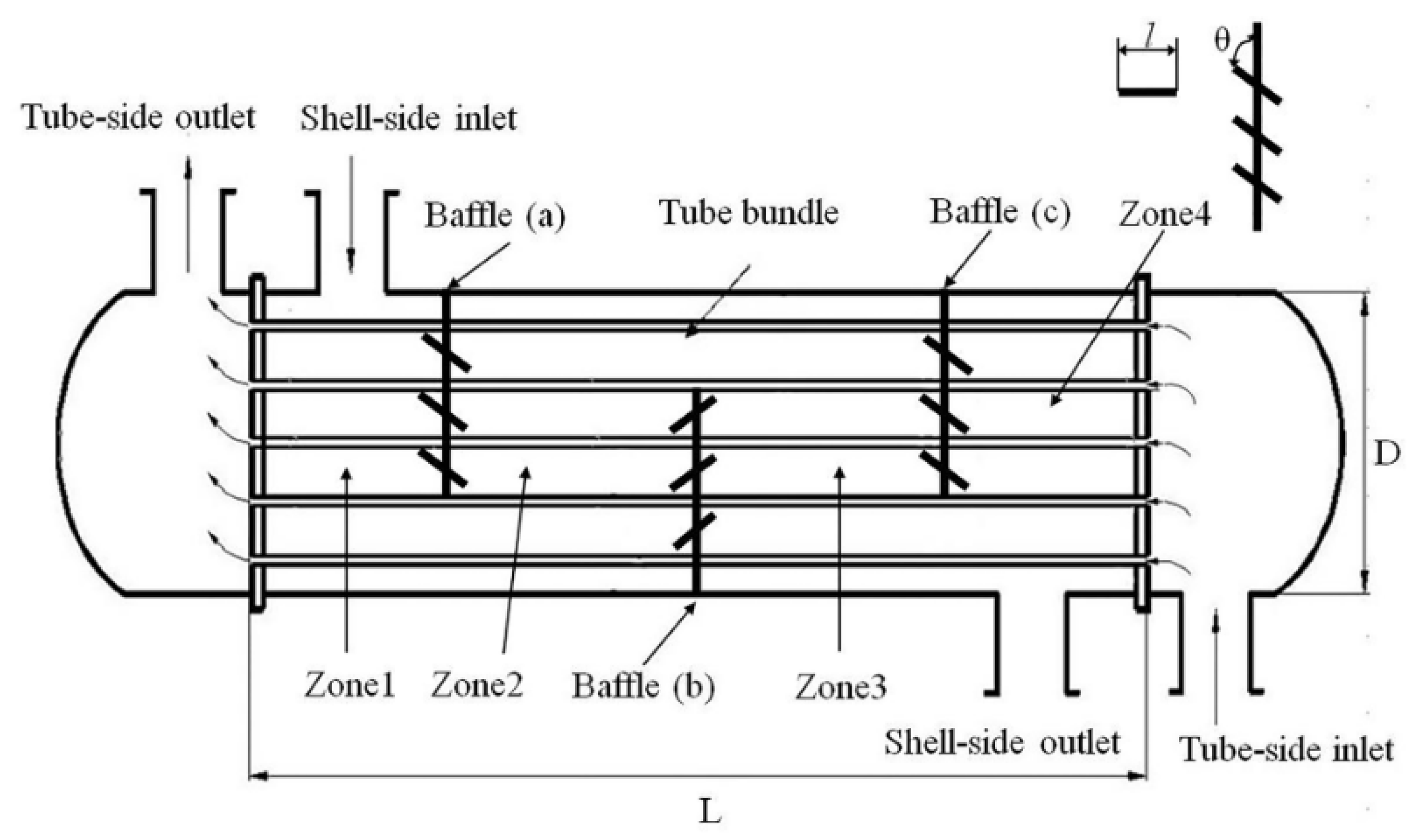
The embedded louver structure is formed by slotting in the gap of the baffle and inserting louvers. Figure 1 shows the three-dimensional internal structure of ELB-STHX designed in this study, which is established in Solidworks. Figure 2 shows the model of CSB-STHX used for comparation. In the simulation, the dimensions of the tube side, shell side, and the number of tubes, as well as the geometric parameters of the baffles, are identical for both ELB-STHX and CSB-STHX, as listed in Table 1. To facilitate a detailed analysis of the internal flow in the ELB-STHX, the internal space has been divided into four regions, as shown in Figure 3. Furthermore, the geometric parameters of the embedded louver baffle include the angle (θ) between the louver and the radial direction of the baffle, and the length (l) of the louver, which are also shown in Figure 3.
In order to investigate the influences of different θ and l on the performance of the heat exchanger and find the optimal design parameters, various cases that represent ELB-STHXs with different structural parameters are compared in this work. The detailed settings for different cases are listed in Table 2. In these settings, Case 0 is employed for the comparison between the ELB-STHX and the CSB-STHX. Case 1–1 to Case 1–3 are ELB-STHXs with the same louver number and louver length but with different angles. Case 2–1 to Case 2–5 and Case 1–3 are ELB-STHXs with the same louver number and louver angles, but with different louver lengths. The louver angles cover three cases, 30°, 45°, and 60°, while the louver lengths vary across six different conditions: 40 mm, 46 mm, 54 mm, 65 mm, 82 mm, and 108 mm. Moreover, the performance under different shell side fluid velocities for each condition was investigated, with velocities varying across five scenarios: 0.5 m/s, 0.75 m/s, 1.0 m/s, 1.25 m/s, and 1.5 m/s.

2.2. Mathematic Model and Boundary Condition Setting

During the simulation of the shell side fluid of the two types of equipment, the standard k-ε model is applied [31,32,33]. Governing equations of a fully developed turbulence fluid flow are shown as follows:
The tracking of fluid is accomplished by the solution of a continuity equation which has the following form:
u i x i = 0
The momentum equation for models of the two heat exchangers takes the following form:
ρ u i u j x j = x j μ u i x j P x i
In this dissertation, the liquid density ρ is constant.
The energy equation of the shell side fluid has the following form:
ρ u j T x j = x j λ c p T x j
The k-ε equation is as follows
ρ u j k x j = x j μ + μ l σ k k x j + μ l u i x j u i x j + u j x i ρ ε
ρ ε u i x i = x j μ + μ t σ ϵ ϵ x j + c 1 ε k μ l u i x j u i x j + u j x i c 2 ρ ε 2 k
μ l = ρ c μ k 2 ε
where c1 and c2 are constant. Moreover, cμ in the expression is a function of rotation rate and mean strain. Referring to the research of Lei et al. [34], in the simulation of this study, the cμ value is set to 0.0845.
In this study, the working shell side fluid is water, and its thermophysical property parameters are shown in Table 3.
It is worth noting that this study focuses on the fluid flow and heat transfer in the shell side of the heat exchange equipment; therefore, in the simulation, the temperature of the tube bundle is taken as a constant to simplify the calculation [35,36]. The detailed boundary condition settings are listed in Table 4.
In the discrete solution of the above governing equations by the finite volume method, the coupling of pressure and velocity is performed by the SIMPLEC algorithm [37,38]. The QUICK approach is applied to discretize the momentum and diffusion terms, while a second-order upwind method is used to discretize the remaining terms, including pressure and energy. For the energy equation, the convergence residual is 1 × 10⁻⁶, while for the other equations, it is 1 × 10⁻⁴. The simulation works are carried out on Ansys Fluent 2023.

2.3. Grid Generation

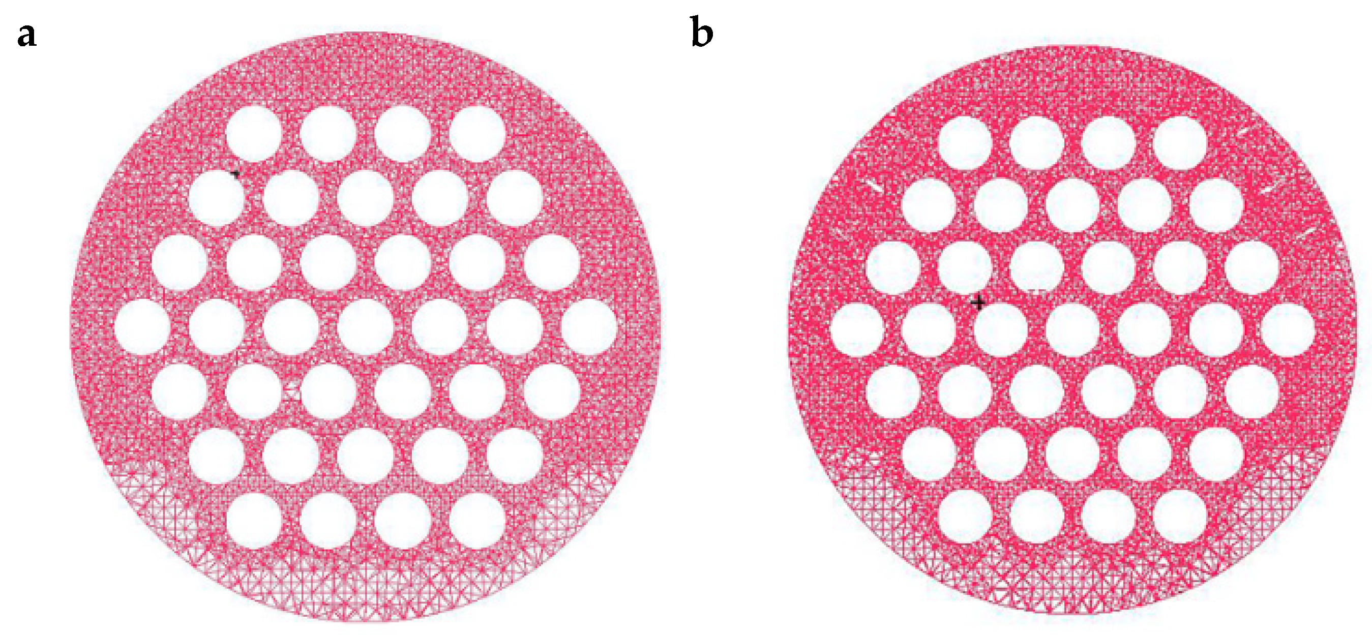
The grid generation of the two equipment models was performed in ICEM 2021. Considering the complex structure of the research object in this study, the normal tetrahedral unstructured grid is employed for numerical simulation [39]. The grids adjacent to the tube wall surface, baffles, and louvers were densified. Figure 4a,b show the cross-section grid of the CSB-STHX and ELB-STHX, respectively. To save computational resources and ensure the accuracy of simulation results, for both kinds of heat exchangers, five sets of grids with different numbers were generated for the independence test. The grid numbers of the CSB-STHX are 0.753, 1.285, 2.044, 2.524, and 3.103 million, respectively, and the grid numbers of the ELB-STHX are 0.687, 1.167, 2.106, 2.693, and 3.062 million, respectively. When the inlet velocity of the shell side fluid is 0.75 m/s, the numerical calculation results of the two exchangers with different grid numbers are as shown in Table 5. It can be found that when the grid numbers of the CSB-STHX are 2.524 million and 3.103 million, the relative error of the ∆P of shell side fluid is less than 1.0%. In addition, while the grid numbers of the ELB-STHX are 2.693 million and 3.062 million, the relative error of the ∆P is also less than 1.5%. Therefore, it is finally determined that CSB-STHX and ELB-STHX are numerically simulated using grid numbers of 2.524 million and 2.693 million, respectively.

2.4. Data Processing

The h and ∆P were applied to evaluate the shell side performance of the heat exchanger [40,41,42]. According to the Fourier Law, h could be obtained from Equation (7) to Equation (10). The calculation of the ∆P of shell side fluid is shown in Equation (11).
h = Q T m · A
Q = M · C P · T o u t T i n
T m = T t u b e T i n T t u b e T o u t l n T t u b e T i n / T t u b e T o u t
A = n π d t u b e L
P = P i n P o u t
where Q represents the heat flow rate, A represents the effective heat transfer area, and ∆Tm represents the log-mean temperature difference between the shell side and tube side. M is the flow rate of fluid in the shell side, cp is the specific heat capacity, and Tin and Tout are the inlet and outlet temperature of shell side fluid. Ttube is the tube temperature, n is the number of tubes, dtube is the outer diameter of the tube, and L is the tube length. Pin and Pout denote the inlet pressure and outlet pressure of the shell side fluid, respectively.
In addition to the above two indicators, the h per unit ∆P is also commonly applied to compare the performance of different heat exchange equipment. In this study, the comprehensive evaluation factor φ was further defined to analyze the degree of improvement in ELB-STHX, the calculation of which is shown in Equation (12).
φ = h E L B / h C S B P E L B / P C S B
where hELB and hCSB denote the h of ELB-STHX and CSB-STHX under the same working conditions, respectively, and ∆PELB and ∆PCSB represent the ∆P on the shell side of ELB-STHX and CSB-STHX, respectively.

2.5. Model Verification

In order to verify the reliability of the model establishment, simulation, and solution method, the simulation results are compared with the experimental investigation results obtained by Chen et al. [43]. They investigated the influence of various baffles like single-segmental and double- and triple-layer flower baffles on h and ∆P, and the experimental test data of STHX with a single-segmental baffle was chosen for verification. The comparison of simulated and experimental values of h and ∆P are shown in Figure 5a and Figure 5b, respectively. The results indicate that with the increase in fluid velocity, both the actual and simulated h and ∆P gradually increase, and the deviations also progressively increase. The maximum deviation between the simulated h and experimental h is 10.7% while that of simulated ∆P and actual ∆P is 14.9%. The deviation of h is smaller compared to ∆P. The reason for this phenomenon is mainly due to the fact that the leakage between the baffle and the tube bundle existed in the experiment process, and when the three-dimensional model was established, it was simplified as a seamless structure. As a result, the deviation between the simulation and experimental ∆P is more pronounced, and the simulation result is larger than the experimental result. Nevertheless, considering that the maximum deviation in both h and ∆P is less than 15%, the numerical model developed and solution approaches applied in this study are still considered reliable.

3. Results and Discussion

3.1. Performance Comparison of the Two Kinds of Heat Exchanger

Different flow zones have been defined in the model to make it easier to analyze the velocity, temperature, and pressure fields of the shell side fluid at various positions. As shown in Figure 3, there are four zones numbered as zone 1–4 in total, which bound each other by a baffle, and there are three baffles denoted as (a)–(c), respectively. Case 0 and Case 1–2 are employed for comparison in this section.

3.1.1. Velocity Distribution

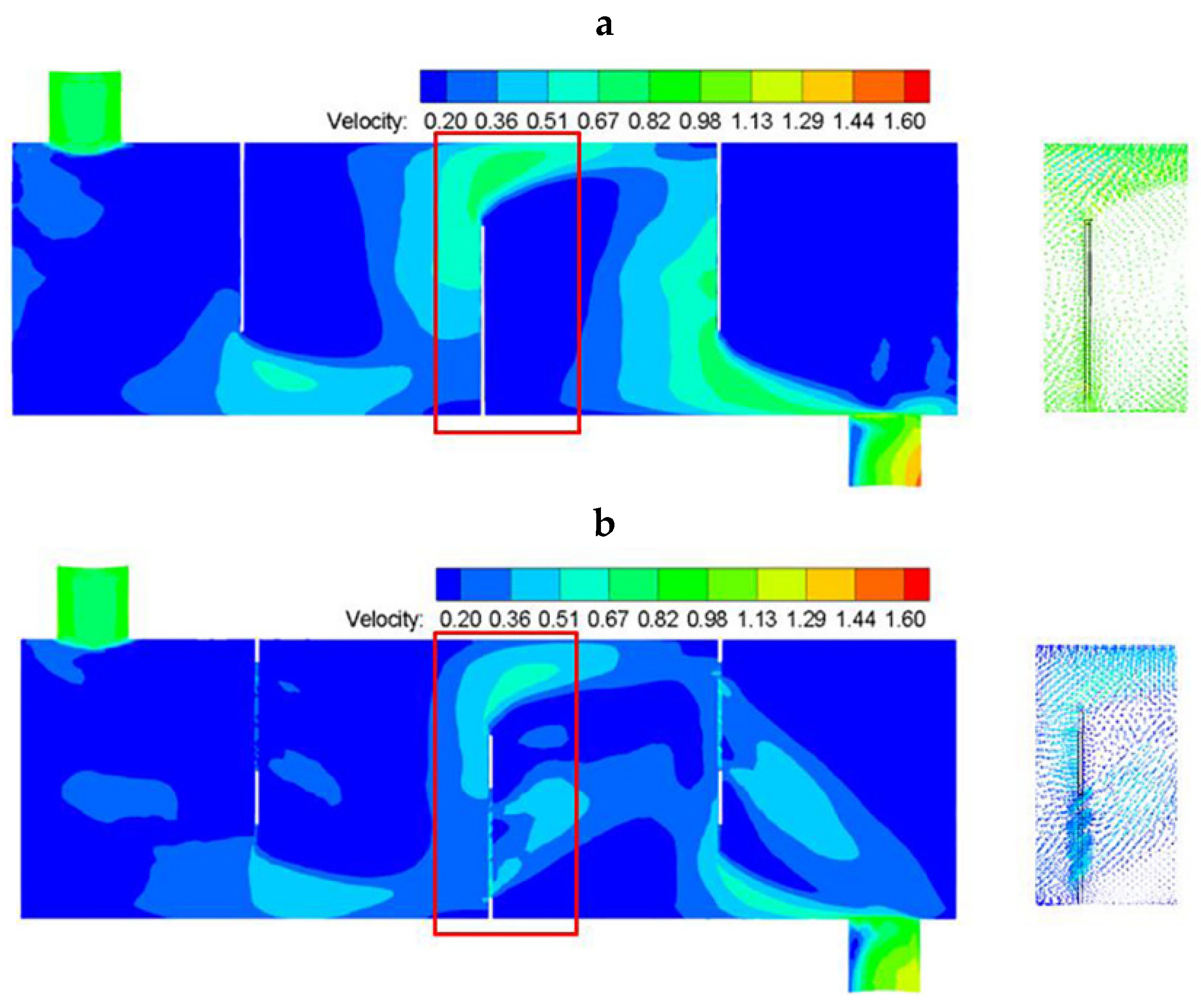
The fluid velocity cloud diagram of the two types of heat exchange equipment and the local velocity vector near the baffle (b) are shown in Figure 6. Figure 6a represents case 0 and Figure 6b represents Case 1–2. In Figure 6, the inlet velocities of the shell side fluid are both 1 m/s.
As presented in Figure 6a, the notch area of the baffle is the only fluid channel of the CSB-STHX. The shell side fluid repeatedly flushed the tube bundle laterally, and the overall flow showed a “Z” shape [44]. The fluid velocity is higher in the gap area of baffle (b), which can reach 0.63 m/s. In addition, on the windward side of the baffle (b), the direction of the fluid velocity changed sharply due to the lateral blocking effect of the baffle. When the fluid reaches the leeward side, the sudden increase in the flow area causes the flow velocity to decrease and forms a large-area flow dead zone. The depth of this part of the area accounts for about half of the distance between adjacent baffles.
It can be seen from Figure 6a,b that the fluid velocity distribution of the ELB-STHX is relatively uniform, and the velocity variation before and after the baffle is small. The shell side flow mainly consists of two channels: a large channel located in the baffle gap region and a small channel in the louver region. The average velocities in these two regions around baffle (b) reach approximately 0.51 m/s and 0.33 m/s, respectively. This special structure allows the fluid passing through the louver region to maintain a nearly constant flow direction and form an arc-shaped trajectory after crossing the baffle, while the fluid passing through the gap region exhibits a “Z”-shaped flow pattern. Together, these two flow forms determine the overall shell side flow characteristics.
Furthermore, based on the defined velocity threshold of 0.2 m/s, the area ratio of the stagnant (dead) zones in ELB-STHX was found to be significantly smaller than that in CSB-STHX. This indicates that the ELB-STHX structure effectively mitigates the formation of large-scale dead zones, resulting in a more uniform velocity field and improved heat transfer performance.

3.1.2. Temperature Distribution

The temperature distribution of the two pieces of equipment is plotted in Figure 7. It was found that the fluid temperature of the two both gradually increases along the flow direction. However, in the CSB-STHX, the temperature change gradient on both sides of the baffle is larger, while in the ELB-STHX, the temperature gradient is smaller. Particularly, there is a high-temperature zone behind the baffle in the CSB-STHX. The reason for this phenomenon is that in the CSB-STHX, due to the large area of fluid retention in the leeward side of the baffle, the heat exchange time between the shell side fluid and the tube bundle in this part of the area is prolonged, thus obtaining more heat, inducing a high-temperature zone and increasing the temperature gradient in the two sides of the baffle. Unlike in the CSB-STHX, as the fluid flow before and after the baffle is relatively continuous in the ELB-STHX, the retention phenomenon no longer appears in a large area. Therefore, on both sides of the baffle, the average heat exchange time between the fluid and the tube bundle is not much different, and the temperature change gradient is small.
Temperature distributions of the cross-sections of different positions of the two pieces of equipment are further plotted in Figure 8. Three representative positions were chosen: the inlet and outlet of the shell side, and the leeward side of the baffle (b). The distance between the section of the three positions and the left end of the shell is 250 mm, 1050 mm, and 675 mm, respectively. It can be found that in the ELB-STHX, the mean fluid temperatures at the positions of x = 250 mm, x = 675 mm, and x = 1050 mm are 0.34 °C, 3.08 °C, and 2.12 °C higher, respectively, compared to those in the CSB-STHX. This is mainly because the double-track flow of fluid guided by the louver structure makes the overall heat exchange between the shell side fluid and the tube bundle more sufficient and uniform, thus increasing the average fluid temperature in the non-retention area. These results indicate that the ELB-STHX facilitates more effective heat exchange, improving the overall thermo-hydraulic performance of the equipment.

3.1.3. Pressure Distribution

Figure 9 presents the pressure distribution of the CSB-STHX and the ELB-STHX. It was found that in the CSB-STHX, the pressure gradient of fluid is obvious from the windward side to the leeward side of the baffle. When the fluid flows through the baffle (b), the pressure is reduced to 298.34 Pa, which is approximately 50.24 Pa higher than that in the ELB-STHX. The main reason for this phenomenon is that the fluid velocity vector changes little, and the pressure changes continuously, on the windward side. However, on the leeward side, due to the significant blocking effect of the baffle, part of the fluid passing through the notch area flows to the next baffle at a high speed, while another part of the low-speed fluid remains in the lower portion of the leeward side and forms a static pressure, resulting in a large pressure difference between the two sides of the baffle [45]. This phenomenon occurs at all baffles on the shell side, and the superposition of local larger pressure loss at each baffle makes the total ∆P of the CSB-STHX higher. Similarly to the CSB-STHX, the pressure on the windward side of the baffle of the ELB-STHX changes continuously. In addition, the diversion effect of the louver will cause part of the fluid on the windward side to reach the leeward side through the fluid channel. Due to the fluid flow continuity before and after the baffle, there is no large area of static pressure zone behind the baffle. As expected, the pressure difference between the windward side and the leeward side is reduced, and the local loss at the baffle is greatly reduced.

3.1.4. h and △P

The discussion above analyzed the velocity, temperature, and pressure distribution on the shell side of the two types of heat exchange equipment qualitatively. In order to compare the h and ∆P on the shell side quantitatively, the graphs of h and ∆P, as a function of the fluid velocity, are plotted.
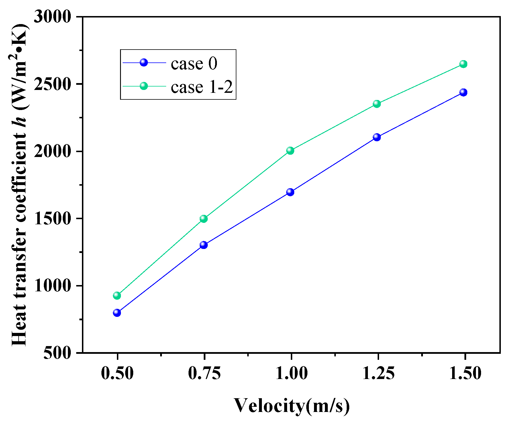
Figure 10 shows the variation in the h of the CSB-STHX and ELB-STHX. The results indicate that with the increase in fluid velocity, the h of both the two types of heat exchange equipment are increased. The phenomenon is primarily caused by an increase in fluid velocity, which raises the turbulence of the shell side fluid and the convective h between the fluid and the tube bundle, enabling more heat exchange. In addition, when the fluid velocity is the same, the h of the CSB-STHX is slightly smaller than that of the ELB-STHX, and the difference was 128.86 W/m2·K to 212.89 W/m2·K. This result also verified that the louver structure can effectively improve the h of the heat exchange equipment.
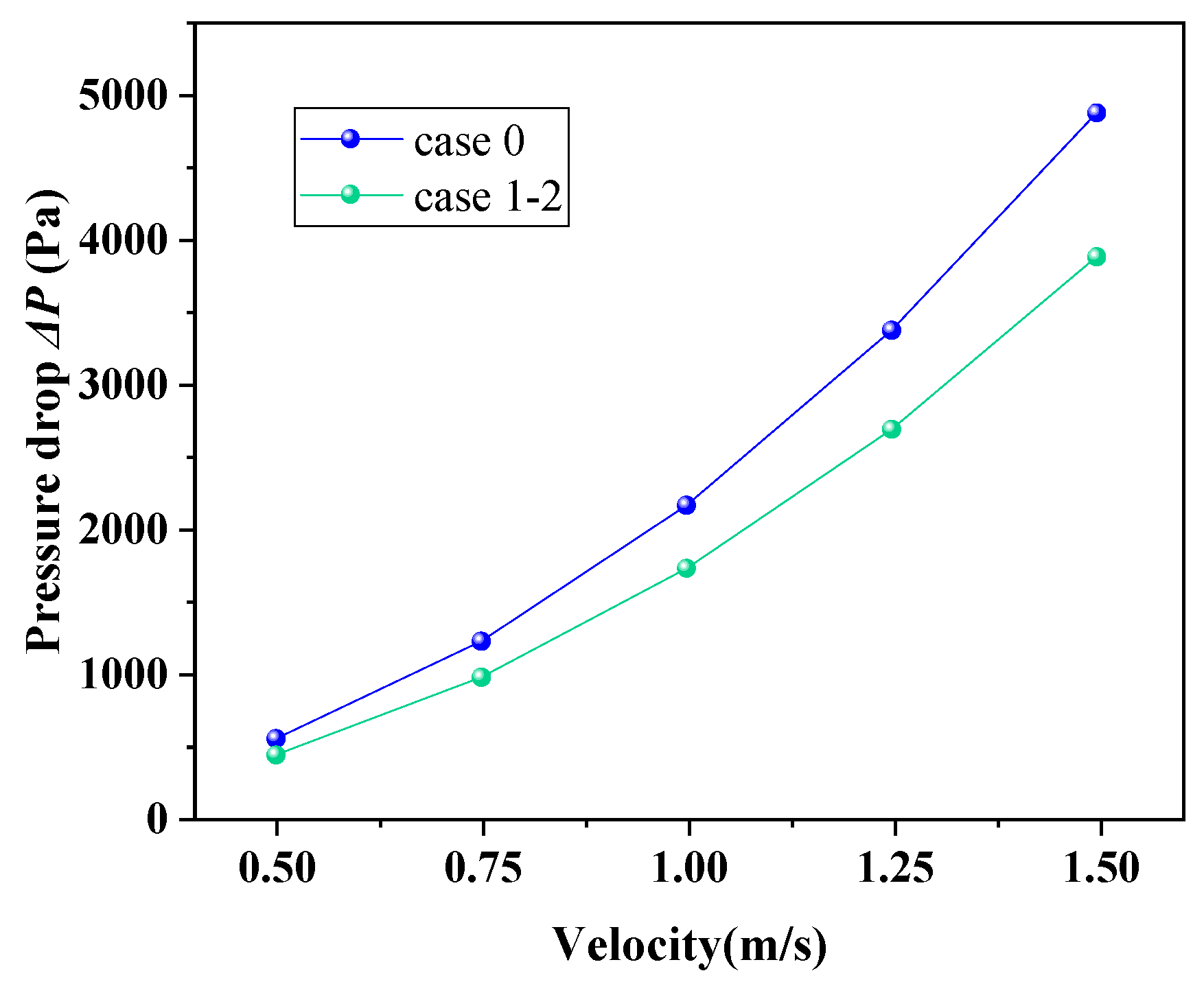
Figure 11 presents the variation in fluid ∆P in the shell side of CSB-STHX and ELB-STHX. It can be found that the ∆P on the shell side of the two kinds of heat exchange equipment both increase with the increase in fluid velocity. When the velocity increased from 0.5 m/s to 1.5 m/s, the ∆P on the shell side of the ELB-STHX changed from 421.6 Pa to 3878.4 Pa, and that of the CSB-STHX changed from 535.4 Pa to 4878.2 Pa. This is related to the greater resistance loss due to the higher fluid velocity. Moreover, when the fluid velocity is the same, ∆P of the ELB-STHX is 20.5–21.3% smaller than that of the CSB-STHX.

3.2. Effect of Structural Parameters on the Performance of ELB-STHX

3.2.1. The Effects of θ on h

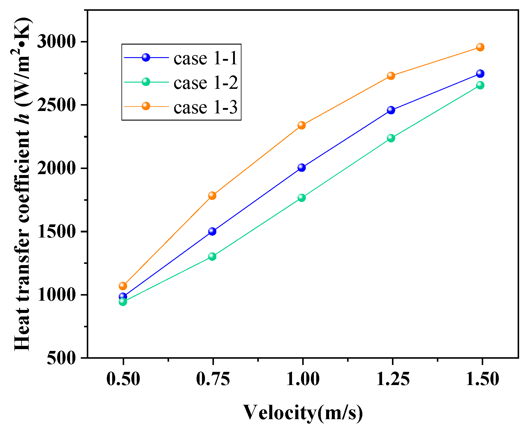
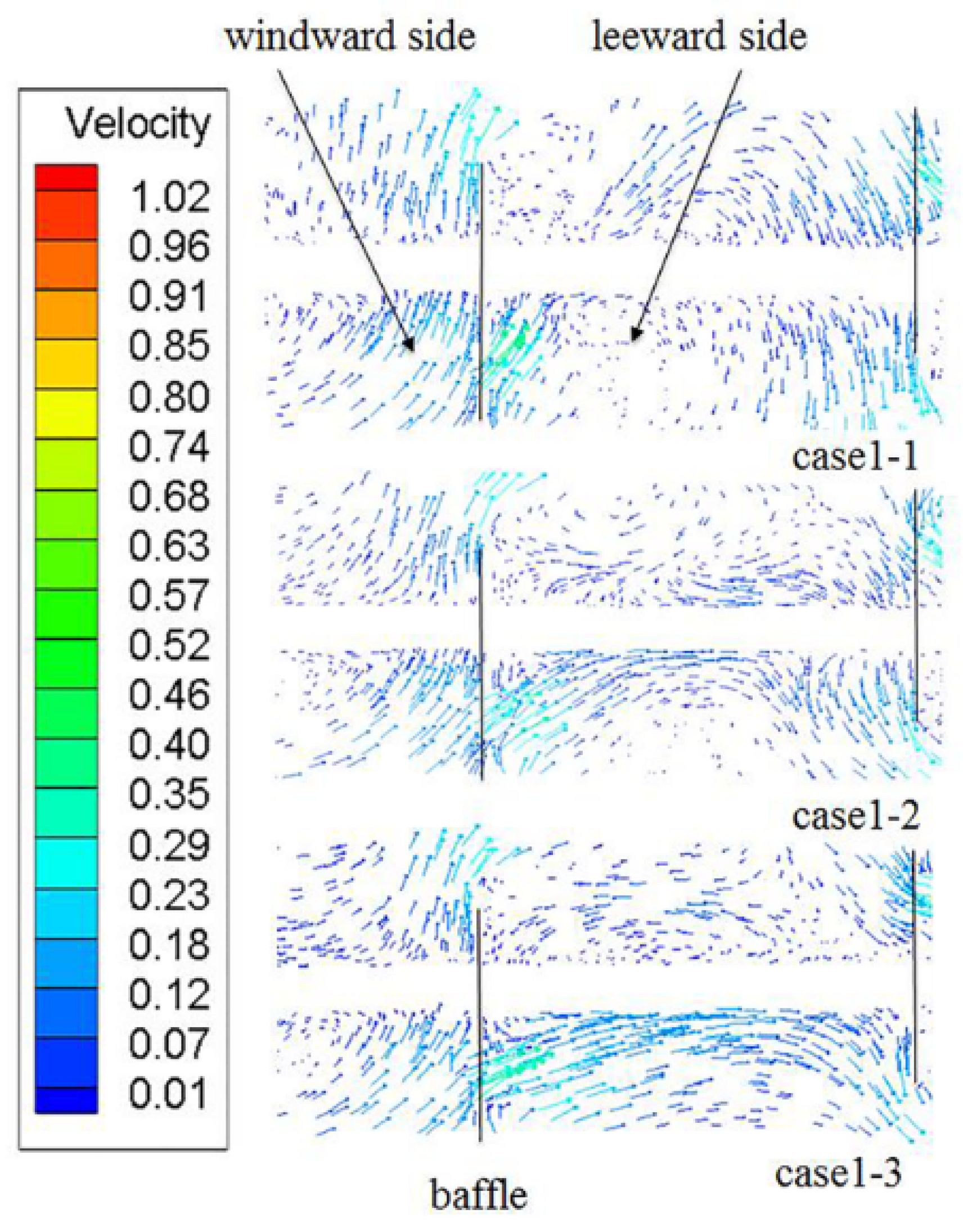
The influence of the louver angle on the h of ELB-STHX is presented in Figure 12. In Case 1-1, Case 1-2, and Case 1-3, the louver angles were 30°, 45°, and 60°, respectively. Figure 12 indicates that h does not show a monotonic change with the increase in louver angle; it firstly decreases and then increases with the increase in θ. When the θ is 60°, h reaches the largest value, which is 1050.4–2965.2 W/m2∙K and 21.8–33.5% higher compared with the CSB-STHX. Based on the velocity vectors in Figure 13, this phenomenon can be explained as follows. On the one hand, with the increase in θ, the area between adjacent louvers and the flow rate of the louver channel both increase, and the area of the flow dead zone on the leeward side of the baffle decreases as a result. The scouring effect of shell side fluid to the tube bundle on the leeward side is enhanced, which is beneficial to reducing the fluid boundary layer of its outer wall in this area so that the fluid and the tube bundle can be fully contacted and induce an increased tendency in h. On the other hand, as shown in Figure 13, when θ is 30°, the louver can guide the fluid to produce a higher head, which makes it merge with the fluid passing through the gap area eventually. This mixed flow has a stronger scouring effect on the tube bundle at the baffle leeward side; therefore, h is slightly higher than Case 1–2, but still lower than Case 1–3.

3.2.2. The Effects of θ on △P

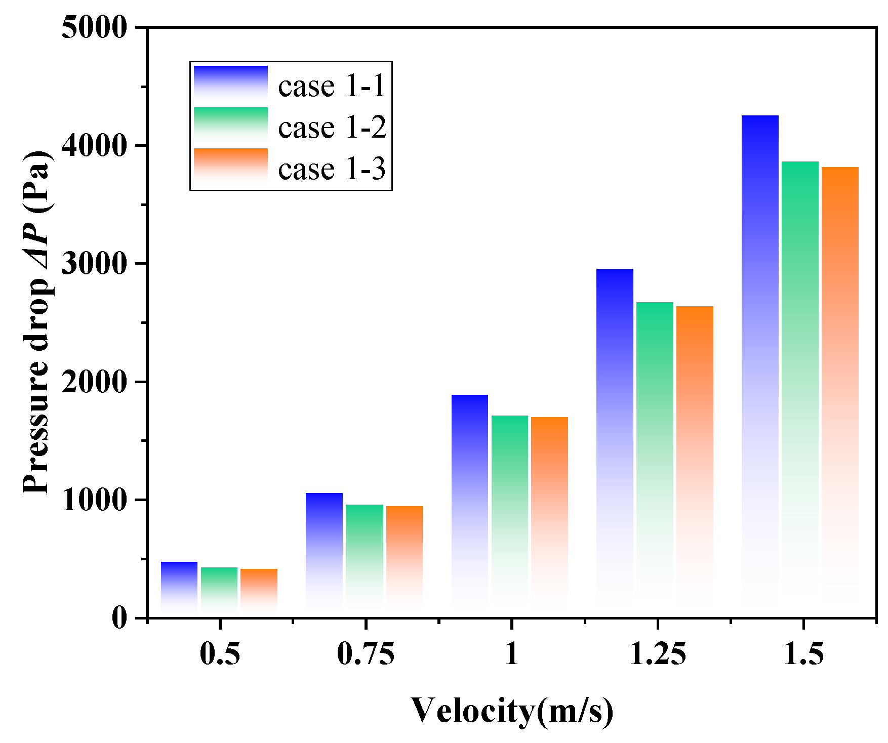
The influence of the louver angle on △P of the ELB-STHX is presented in Figure 14. The results indicate that with the increase in θ, the △P of the ELB-STHX decreases, and when the louver angle was changed from 30° to 45°, the ∆P decreased more obviously. When the louver angle reaches 60°, the △P of the heat exchange equipment can be reduced by 21.9–26.8% compared with the CSB-STHX. This phenomenon may be related to the stronger drainage effect of louvers with larger angles. As shown in Figure 13, the flow rate guided by the louver increases with the increase in louver angle. It essentially results from the increased area of the fluid channel between adjacent louvers. As a result, the flow resistance of the shell side fluid is reduced, and the ∆P is also reduced.

3.2.3. The Effects of θ on φ

Equation (12) illustrates the way the comprehensive evaluation factor is calculated. It is worth noting that φ is in fact the ratio of h/△P of the ELB-STHX to the CSB-STHX. It represents the relative magnitude of h per unit △P of the two kinds of heat exchange equipment. The higher the φ is, the better performance of the embedded louver heat exchange equipment. The effect of the louver angle on the evaluation factor can be found in Figure 15. It is shown that the comprehensive evaluation factor of the ELB-STHX increases gradually with the increase in the louver angle. When the louver angle increased to 60°, the evaluation factor could reach 1.53–1.74, which means that the h of the ELB-STHX with a louver angle of 60° can reach more than 1.5 times that of the CSB-STHX under the same pump consumption.

3.2.4. The Effects of l on h

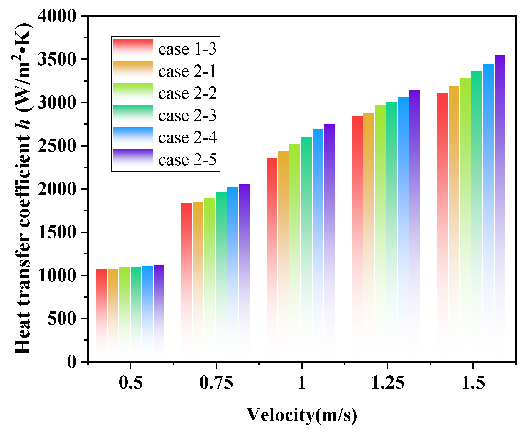
The influence of louver length on the h of the ELB-STHX is presented in Figure 16. Case 1–3, Case 2–1, Case 2–2, Case 2–3, Case 2–4, and Case 2–5 denote the ELB-STHX with a louver length of 40 mm, 46 mm, 54 mm, 65 mm, 82 mm, and 108 mm, respectively. It is worth noting that in these cases, the louver angle is fixed at 60°. Numerical simulation results show that h gradually increases with an increase in louver length. Increasing the louver length from 40 mm to 108 mm, the h increases by 46.5 W/m2·K to 439.7 W/m2·K under different fluid velocities. This is primarily due to the fact that the longer the l is, the stronger the fluid disturbance on both sides of the baffle, especially on the leeward side, which enhances the heat exchange between the fluid and the tube bundle. Furthermore, when the length is longer, the kinetic energy is converted more to overcome the height difference when the fluid flows along the louver. However, the potential energy of the fluid will be converted into kinetic energy again when it flows out of the end of the louver, which increases the scouring of the tube bundle and strengthens the heat exchange in the leeward side of the baffle.

3.2.5. The Effects of l on △P

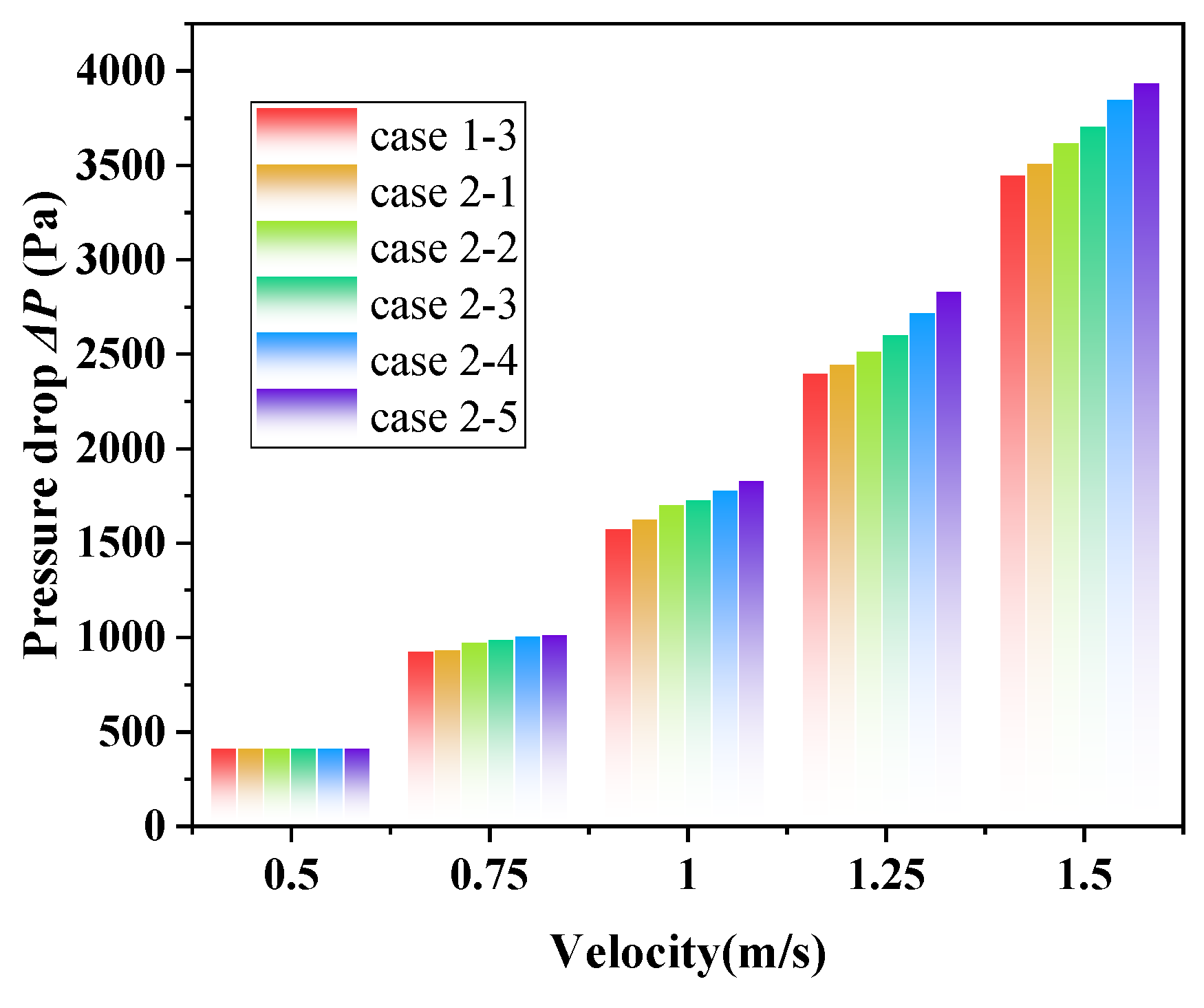
Figure 17 shows the influence of louver length on the △P of the shell side of ELB-STHX. The results show that △P also increases monotonically with an increase in louver length. Increasing the louver length from 40 mm to 108 mm at a fluid velocity of 1.5 m/s will cause △P to rise from 2.1 Pa to 491.6 Pa. The reason for this phenomenon is that when the length is increased, the louver with a fixed angle is more likely to form a significant height difference on the windward and leeward sides of the baffle, which makes the height difference to be overcome greater when the fluid flows along the louver. As a result, the resistance loss of the fluid due to friction increases here, and the total △P increases.

3.2.6. The Effects of l on φ

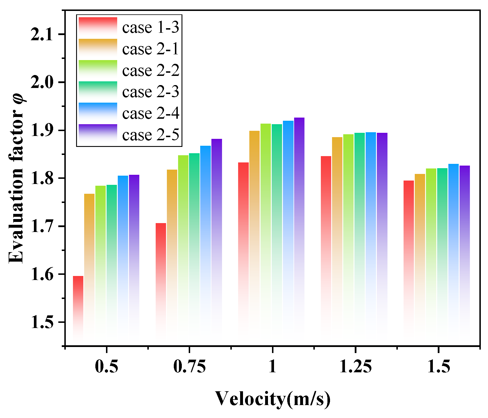
Figure 18 presents the impact of louver length on the comprehensive evaluation factor. It indicates that when the fluid velocity is low, φ gradually increases as the louver length increases. However, when the fluid velocity exceeds 1.0 m/s, φ for the ELB-STHXs decreases across all cases, and the differences between these cases become relatively small. Notably, at fluid velocities of 0.5 m/s and 0.75 m/s, increasing the louver length from 40 mm to 46 mm results in a 6.6% and 10.8% improvement in the evaluation factor, respectively. However, further increasing the length from 46 mm to 108 mm only yields marginal improvements of 2.3% and 3.5% in the evaluation factor. When the fluid velocity exceeds 1.0 m/s, increasing the louver length from 46 mm to 108 mm results in an average improvement of only 0.97% in the evaluation factor. This finding indicates that when the louver length exceeds 46 mm, further increases provide diminishing benefits. Therefore, considering both the manufacturing costs and performance of the heat exchange equipment, the louver length of 46 mm—equivalent to 1/7 of the distance between adjacent baffles—is a more suitable design choice for the ELB-STHX.

4. Conclusions

Based on the structure of the segmental baffle, this study proposes a structural support with embedded louvers and establishes a full three-dimensional physical model of this type of STHX. The numerical simulation method is applied to study the shell side fluid velocity, temperature, and pressure field distribution, and the heat transfer enhancement and energy-saving mechanism are analyzed by comparison with the common segmental baffle heat exchanger. The influences of key design parameters covering louver angle and louver length on the h, ∆P, and comprehensive evaluation factor are explored. The main conclusions are as follows:
(1)
This improved baffle structure changes the “Z” flow of the shell side fluid of the CSB-STHX into a coexisting form of “Z” and circular arc flow, which effectively reduces the area of the flow dead zone and enhances fluid disturbance in the leeward side of the baffle.
(2)
In the ELB-STHX, the temperature gradient on both sides of the baffles is relatively small. At the inlet, the outlet of shell side fluid, and the middle section of the heat exchange equipment, the average fluid temperatures are 0.34 °C, 2.12 °C, and 3.08 °C higher, respectively, compared to those in the CSB-STHX.
(3)
The guiding effect of the louvers ensures a continuous pressure variation between the windward and leeward sides of the baffles, resulting in a lower shell side pressure loss compared to the CSB-STHX.
(4)
Under the same fluid velocity, compared to the CSB-STHX, the ELB-STHX increases the h by 8.75% to 16.4% while reducing pressure loss by 20.5% to 21.3%.
(5)
As the louver angle increases, the h initially rises and then declines, while the shell side ∆P decreases monotonically. The comprehensive evaluation factor reaches its maximum when the louver angle is 60°.
(6)
Increasing the louver length leads to a simultaneous rise in both the h and ∆P. However, when the louver length is extended from 1/7 to 1/3 of the distance between adjacent baffles, the improvement in the comprehensive evaluation factor is minimal. Therefore, a louver length of 1/7 the distance between adjacent baffles is the optimal design choice.

Author Contributions

Conceptualization, X.Y.; software, X.Y. and R.H.; validation, R.H. and Z.Z.; data curation, Y.Z. (Yuanyuan Zhang); writing—original draft preparation, X.Y.; visualization, Y.Z. (Yu Zhang). All authors have read and agreed to the published version of the manuscript.

Funding

This research received no external funding.

Data Availability Statement

Data will be made available on request.

Acknowledgments

The authors would like to express their sincere gratitude to the reviewers and editors for their professional review of this article. Their valuable comments and suggestions have greatly contributed to improving the quality of this article.

Conflicts of Interest

The authors declare no conflict of interest.

Nomenclature/Abbreviations

Nomenclature
θLouver angle (°)QHeat flow rate (W/m2)
lLouver length (mm)TinInlet temperature of shell side fluid (K)
DDiameter of shell (mm)VinInlet velocity of shell side fluid (m/s)
din (out)Diameter of shell inlet (outlet) (mm)TtubeTemperature of the tube (K)
LTube length (mm)hHeat transfer coefficient (W/m2∙K)
dtubeOuter diameter of tube (mm)PPressure drop (Pa)
nNumber of tubesAEffective heat transfer area (m2)
ZDistance between adjacent tubes (mm)TmLog-mean temperature difference (K)
NNumber of bafflesMFlow rate (kg/s)
HCut ratio of baffleToutOutlet temperature of shell side fluid (K)
BDistance between adjacent baffles (mm)PinInlet pressure of the shell fluid (Pa)
ρLiquid density (kg/m3)PoutOutlet pressure of the shell fluid (Pa)
c1, c2ConstantφComprehensive evaluation factor
cμFunction of rotation rates and mean strainhELBHeat transfer coefficients of ELB-STHX (W/m2∙K)
λThermal conductivity (W/m⋅K)hCSBHeat transfer coefficients of CSB-STHX (W/m2∙K)
νKinematic viscosity coefficient (m2/s)PELBShell side pressure drop of ELB-STHX (Pa)
PrPrandtl NumberPCSBShell side pressure drop of CSB-STHX (Pa)
CpSpecific heat capacity (J/kg⋅K)
Abbreviations
STHXshell-and-tube heat exchanger
THB-STHXshell-and-tube heat exchangers with trefoil-hole baffles
CBSTT-STHXshell-and-tube heat exchanger with clamping antivibration baffles and square twisted tubes
SGCT-STHXshell-and-tube heat exchanger with segmental baffles and cylindrical tubes
ELB-STHXshell-and-tube heat exchanger with embedded louver segmental baffle support
CSB-STHXshell-and-tube heat exchanger with common segmental baffle

References

  1. Stehlík, P.; Wadekar, V.V. Different Strategies to Improve Industrial Heat Exchange. Heat Transf. Eng. 2010, 23, 36–48. [Google Scholar] [CrossRef]
  2. Abbasian Arani, A.A.; Moradi, R. Shell and tube heat exchanger optimization using new baffle and tube configuration. Appl. Therm. Eng. 2019, 157, 113736. [Google Scholar] [CrossRef]
  3. Zhang, B.; Yang, Y.; Wu, Y. Study on the performance of a novel sinusoidal staggered shell and tube heat exchanger without baffle with experiment verification and CFD modeling. J. Energy Storage 2025, 114, 115832. [Google Scholar] [CrossRef]
  4. Sundén, B. Computational Fluid Dynamics in Research and Design of Heat Exchangers. Heat Transf. Eng. 2007, 28, 898–910. [Google Scholar] [CrossRef]
  5. Kücük, H. The effect of minichannels on the overall heat transfer coefficient and pressure drop of a shell and tube heat exchanger: Experimental performance comparison. Int. J. Therm. Sci. 2023, 188, 108217. [Google Scholar] [CrossRef]
  6. Shoaei, M.; Kowsary, F. Multi-objective optimization of geometrical parameters of a pipe with internal baffle using artificial neural networks and genetic algorithm. Appl. Therm. Eng. 2025, 262, 125212. [Google Scholar] [CrossRef]
  7. Marzouk, S.A.; Al-Sood, M.M.A.; El-Fakharany, M.K.; El-Said, E.M.S. A comparative numerical study of shell and multi-tube heat exchanger performance with different baffles configurations. Int. J. Therm. Sci. 2022, 179, 107655. [Google Scholar] [CrossRef]
  8. Zhou, J.; Wang, X.; Li, J.; Lu, H. CFD analysis of mist/air film cooling on a flat plate with different hole types. Numer. Heat Transf. Part A Appl. 2017, 71, 1123–1140. [Google Scholar] [CrossRef]
  9. Wang, Q.; Zeng, M.; Ma, T.; Du, X.; Yang, J. Recent development and application of several high-efficiency surface heat exchangers for energy conversion and utilization. Appl. Energy 2014, 135, 748–777. [Google Scholar] [CrossRef]
  10. Dogan, S. Baffle angle optimization of a typical shell and tube heat exchanger. Phys. Fluids 2025, 37, 015165. [Google Scholar] [CrossRef]
  11. Shabani Samghabadia, A.; Abbasian Arani, A.A.; Yosofvand, H. Thermo-hydraulic efficiency enhancing: Optimized ladder fold baffle structure with cam and circle tube bundle. Int. J. Therm. Sci. 2024, 196, 108680. [Google Scholar] [CrossRef]
  12. Al-darraji, A.R.; Marzouk, S.A.; Aljabr, A.; Almehmadi, F.A.; Alqaed, S.; Kaood, A. Enhancement of heat transfer in a vertical shell and tube heat exchanger using air injection and new baffles: Experimental and numerical approach. Appl. Therm. Eng. 2024, 236, 121493. [Google Scholar] [CrossRef]
  13. Marzouk, S.A.; Abou Al-Sood, M.M.; El-Said, E.M.S.; Younes, M.M.; El-Fakharany, M.K. A comprehensive review of methods of heat transfer enhancement in shell and tube heat exchangers. J. Therm. Anal. Calorim. 2023, 148, 7539–7578. [Google Scholar] [CrossRef]
  14. El Maakoul, A.; Laknizi, A.; Saadeddine, S.; El Metoui, M.; Zaite, A.; Meziane, M.; Abdellah, A.B. Numerical comparison of shell-side performance for shell and tube heat exchangers with trefoil-hole, helical and segmental baffles. Appl. Therm. Eng. 2016, 109, 175–185. [Google Scholar] [CrossRef]
  15. You, Y.; Fan, A.; Lai, X.; Huang, S.; Liu, W. Experimental and numerical investigations of shell-side thermo-hydraulic performances for shell-and-tube heat exchanger with trefoil-hole baffles. Appl. Therm. Eng. 2013, 50, 950–956. [Google Scholar] [CrossRef]
  16. Saad, M.; Munir, A.; Kamran, M.A. Numerical Simulations of Shell and Tube Heat Exchanger with Segmental, Trefoil and Segmented Trefoil Baffles for Performance Comparison. Heat Transf. Eng. 2022, 44, 702–719. [Google Scholar] [CrossRef]
  17. Ma, L.; Wang, K.; Liu, M.; Wang, D.; Liu, T.; Wang, Y.; Liu, Z. Numerical study on performances of shell-side in trefoil-hole and quatrefoil-hole baffle heat exchangers. Appl. Therm. Eng. 2017, 123, 1444–1455. [Google Scholar] [CrossRef]
  18. Rezwan, A.A.; Hossain, S.; Rahman, S.M.A.; Islam, M.A. Heat Transfer Enhancement in an Air Process Heater Using Semi-Circular Hollow Baffles. Procedia Eng. 2013, 56, 357–362. [Google Scholar] [CrossRef]
  19. Dong, Q.W.; Wang, Y.Q.; Liu, M.S. Numerical and experimental investigation of shellside characteristics for RODbaffle heat exchanger. Appl. Therm. Eng. 2008, 28, 651–660. [Google Scholar] [CrossRef]
  20. Xianhe, D.; Songjiu, D. Investigation of Heat Transfer Enhancement of Roughened Tube Bundles Supported by Ring or Rod Supports. Heat Transf. Eng. 1998, 19, 21–27. [Google Scholar] [CrossRef]
  21. You, Y.; Zhang, F.; Fan, A.; Dai, F.; Luo, X.; Liu, W. A numerical study on the turbulent heat transfer enhancement of Rodbaffle heat exchanger with staggered tubes supported by round rods with arc cuts. Appl. Therm. Eng. 2015, 76, 220–232. [Google Scholar] [CrossRef]
  22. Tan X-h Zhu D-s Zhou G-y Yang, L. 3D numerical simulation on the shell side heat transfer and pressure drop performances of twisted oval tube heat exchanger. Int. J. Heat Mass Transf. 2013, 65, 244–253. [Google Scholar] [CrossRef]
  23. Peng, B.; Wang, Q.; Zhang, C.; Xie, G.; Luo, L.; Chen, Q.; Zeng, M. An Experimental Study of Shell-and-Tube Heat Exchangers With Continuous Helical Baffles. J. HEAT Transf.-Trans. ASME 2007, 129, 1423–1431. [Google Scholar] [CrossRef]
  24. Nagaeswara Rao, B.; Pavanu Sai, J. Numerical investigation of thermo-hydraulic ability of STHX with continuous helical baffles on the shell side. Mater. Today Proc. 2023. [Google Scholar] [CrossRef]
  25. Naqvi, S.M.A.; Wang, Q. Numerical Comparison of Thermohydraulic Performance and Fluid-Induced Vibrations for STHXs with Segmental, Helical, and Novel Clamping Antivibration Baffles. Energies 2019, 12, 540. [Google Scholar] [CrossRef]
  26. Zhang, J.-F.; He, Y.-L.; Tao, W.-Q. 3D numerical simulation on shell-and-tube heat exchangers with middle-overlapped helical baffles and continuous baffles–Part II: Simulation results of periodic model and comparison between continuous and noncontinuous helical baffles. Int. J. Heat Mass Transf. 2009, 52, 5381–5389. [Google Scholar] [CrossRef]
  27. Duan, Z.; Shen, F.; Cao, X.; Zhang, J. Comprehensive effects of baffle configuration on the performance of heat exchanger with helical baffles. Nucl. Eng. Des. 2016, 300, 349–357. [Google Scholar] [CrossRef]
  28. Kumar, R.; Chandra, P. Thermal analysis, pressure drop and exergy loss of energy efficient shell, and triple meshed helical coil tube heat exchanger. Energy Sources Part A Recovery Util. Environ. Eff. 2019, 42, 1026–1039. [Google Scholar] [CrossRef]
  29. Dong, C.; Chen, Y.-P.; Wu, J.-F.; Cao, R.-B. Performance Study of a Circumferential Overlap Trisection Helical Baffle Heat Exchanger at the Shell Side. Heat Transf. Eng. 2015, 36, 1132–1143. [Google Scholar] [CrossRef]
  30. Dong, C.; Chen, Y.P.; Wu, J.F.; Cao, R.B. Numerical Investigation on Circumferential Overlap Trisection Helical Baffle Heat Exchanger. Appl. Mech. Mater. 2013, 389, 1035–1040. [Google Scholar] [CrossRef]
  31. Sun, Y.; Li, D.; Ji, J.; Hua, Z. Numerical study of structural parameters of perforated baffle on heat transfer enhancement in coiled elastic copper tube heat exchanger. Appl. Therm. Eng. 2025, 260, 124993. [Google Scholar] [CrossRef]
  32. Gu, X.; Li, N.; Chen, C.; Zhang, Q.; Wang, G.; Wang, Y. Analysis of fluid retention zones in heat exchangers with segmental baffle and helical baffle. Int. J. Chem. React. Eng. 2022, 20, 681–696. [Google Scholar] [CrossRef]
  33. Cao, X.; Zhang, R.; Chen, D.; Chen, L.; Du, T.; Yu, H. Performance investigation and multi-objective optimization of helical baffle heat exchangers based on thermodynamic and economic analyses. Int. J. Heat Mass Transf. 2021, 176, 121489. [Google Scholar] [CrossRef]
  34. Lei, Y.; Li, Y.; Jing, S.; Song, C.; Lyu, Y.; Wang, F. Design and performance analysis of the novel shell-and-tube heat exchangers with louver baffles. Appl. Therm. Eng. 2017, 125, 870–879. [Google Scholar] [CrossRef]
  35. Sun, Y.; Li, D.; Ji, J.; Hua, Z. Numerical analysis on heat transfer performance of spiral elastic copper tube heat exchanger with helical defectors. Appl. Therm. Eng. 2024, 248, 123298. [Google Scholar] [CrossRef]
  36. Ji, J.; Pan, Y.; Zhang, J.; Shi, B.; Bao, L. Numerical study on the effect of baffle structure on the heat transfer performance of elastic tube bundle heat exchanger. Appl. Therm. Eng. 2024, 238, 122220. [Google Scholar] [CrossRef]
  37. Aslam Bhutta, M.M.; Hayat, N.; Bashir, M.H.; Khan, A.R.; Ahmad, K.N.; Khan, S. CFD applications in various heat exchangers design: A review. Appl. Therm. Eng. 2012, 32, 1–12. [Google Scholar] [CrossRef]
  38. Alqarni, M.M.; Ibrahim, M.; Assiri, T.A.; Saeed, T.; Mousa, A.A.A.; Ali, V. Two-phase simulation of a shell and tube heat exchanger filled with hybrid nanofluid. Eng. Anal. Bound. Elem. 2023, 146, 80–88. [Google Scholar] [CrossRef]
  39. Gerhardt, F.L.C.; Salvo, R.d.V.; Marchi Neto Id Lima RSd Silva, R.C.d. Computational modeling of a thermal energy storage tank coupled to a water-cooled household refrigerator. J. Energy Storage 2021, 41, 102961. [Google Scholar] [CrossRef]
  40. Tan X-h Zhu D-s Zhou G-y Zeng, L.-d. Heat transfer and pressure drop performance of twisted oval tube heat exchanger. Appl. Therm. Eng. 2013, 50, 374–383. [Google Scholar] [CrossRef]
  41. Ambekar, A.S.; Sivakumar, R.; Anantharaman, N.; Vivekenandan, M. CFD simulation study of shell and tube heat exchangers with different baffle segment configurations. Appl. Therm. Eng. 2016, 108, 999–1007. [Google Scholar] [CrossRef]
  42. Zhang, X.; Han, D.; He, W.; Yue, C.; Pu, W. Numerical simulation on a novel shell-and-tube heat exchanger with screw cinquefoil orifice baffles. Adv. Mech. Eng. 2017, 9, 1–12. [Google Scholar] [CrossRef]
  43. Chen, J.; Zhao, P.; Wang, Q.; Zeng, M. Experimental Investigation of Shell-Side Performance and Optimal Design of Shell-and-Tube Heat Exchanger with Different Flower Baffles. Heat Transf. Eng. 2020, 42, 613–626. [Google Scholar] [CrossRef]
  44. Zeyninejad Movassag, S.; Nemati Taher, F.; Razmi, K.; Tasouji Azar, R. Tube bundle replacement for segmental and helical shell and tube heat exchangers: Performance comparison and fouling investigation on the shell side. Appl. Therm. Eng. 2013, 51, 1162–1169. [Google Scholar] [CrossRef]
  45. Roetzel, W.; Lee, D.W. Effect of baffle shell leakage flow on heat transfer in shell-and-tube heat exchangers. Exp. Therm. Fluid Sci. 1994, 8, 10–20. [Google Scholar] [CrossRef]
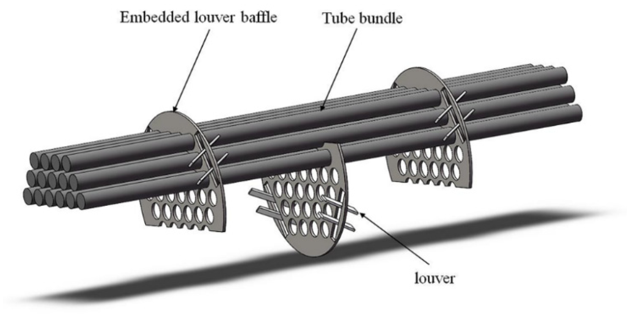
Figure 1. Model of internal structure of ELB-STHX.
Energies 18 05971 g001
Figure 2. Model of the CSB-STHX.
Energies 18 05971 g002
Figure 3. Sketch of the ELB-STHX.
Energies 18 05971 g003
Figure 4. Schematic of grid arrangement in the baffle cross-sectional region. (a) Grid of the CSB-STHX. (b) Grid of ELB-STHX.
Energies 18 05971 g004
Figure 5. Comparison of simulated values with experimental data. (a) Comparison of h. (b) Comparison of ∆P.
Energies 18 05971 g005
Figure 6. Cloud diagram of velocity and the local flow field velocity vector diagram of shell side, (a) the CSB-STHX, and (b) the ELB-STHX.
Energies 18 05971 g006
Figure 7. Cloud diagram of temperature distribution, (a) the CSB-STHX, and (b) the ELB-STHX.
Energies 18 05971 g007
Figure 8. Temperature cloud diagram of cross-section of the CSB-STHX (upper part) and the ELB-STHX (lower part), (a) x = 250 mm, (b) x = 675 mm, (c) x = 1050 mm.
Energies 18 05971 g008
Figure 9. Cloud diagram of pressure distribution, (a) the CSB-STHX, and (b) the ELB-STHX.
Energies 18 05971 g009
Figure 10. Variation in h of the CSB-STHX and ELB-STHX.
Energies 18 05971 g010
Figure 11. Variation in ∆P of the CSB-STHX and ELB-STHX.
Energies 18 05971 g011
Figure 12. Variation in h with change in louver angle.
Energies 18 05971 g012
Figure 13. Velocity vector between baffle (b) and (c).
Energies 18 05971 g013
Figure 14. Variation in △P with change in louver angle.
Energies 18 05971 g014
Figure 15. Variation in φ with change in louver angle.
Energies 18 05971 g015
Figure 16. Variation in h with change in louver length.
Energies 18 05971 g016
Figure 17. Variation in △P with change in louver length.
Energies 18 05971 g017
Figure 18. Variation in φ with change in louver length.
Energies 18 05971 g018
Table 1. Primary geometric parameters of heat exchangers.
ItemDetail
Diameter of shell D (mm)380
Diameter of shell inlet (outlet) din(out)(mm)100
Tube length L (mm)1300
Outer diameter of tube dtube (mm)38
Number of tubes n37
Distance between adjacent tubes Z (mm)48
Number of baffles N3
Cut ratio of baffle H30%
Distance between adjacent baffles B (mm)325
Table 2. Setting of different simulated cases.
ClassificationWorking Condition SettingAngle of Louvers θ (°)Length of Louvers l (mm)Velocity of Shell Side Fluid (m/s)
CSB-STHXCase 0 0.50.751.01.251.5
ELB-STHXCase 1–130400.50.751.01.251.5
Case 1–245400.50.751.01.251.5
Case 1–360400.50.751.01.251.5
Case 2–160460.50.751.01.251.5
Case 2–260540.50.751.01.251.5
Case 2–360650.50.751.01.251.5
Case 2–460820.50.751.01.251.5
Case 2–5601080.50.751.01.251.5
Table 3. Property details.
ItemDetail
ρ999.8 kg/m3
λ0.668 W/m⋅K
ν1.5142 × 10⁻⁶ m2/s
Pr7.02
Cp4195 J/kg⋅K
Table 4. Boundary condition settings.
ItemBoundary Condition AppliedDetail Setting
Shell wallAdiabatic boundary conditionQ = 0 W/m2
Shell side inletVelocity boundary conditionTin = 278.5 K,
Vin = 0.5–1.5 m/s
Shell side outletOutflow boundary condition/
Tube bundle wall boundaryFixed temperature boundary conditionTtube = 308.5 K
Tube side inlet wallAdiabatic boundary conditionQ = 0 W/m2
Tube side outlet wallAdiabatic boundary conditionQ = 0 W/m2
Baffle/Louver boundaryAdiabatic boundary conditionQ = 0 W/m2
Table 5. Grid independence test results.
The CSB-STHXThe ELB-STHX
Grid Number (Million)Pressure Drop of Shell Side (Pa)Relative Error (%)Grid Number (Million)Pressure Drop of Shell Side (Pa)Relative Error (%)
0.7532033.010.6871648.49
1.2852116.924.131.1671688.732.44
2.0442166.672.352.1061719.381.81
2.5242203.411.702.6931748.891.72
3.1032181.890.983.0621729.441.11
Disclaimer/Publisher’s Note: The statements, opinions and data contained in all publications are solely those of the individual author(s) and contributor(s) and not of MDPI and/or the editor(s). MDPI and/or the editor(s) disclaim responsibility for any injury to people or property resulting from any ideas, methods, instructions or products referred to in the content.