Article

Grid-Connected Bidirectional Off-Board Electric Vehicle Fast-Charging System

1
Faculty of Science and Engineering, Swansea University, Bay Campus, Swansea SA1 8EN, UK
2
Cardiff School of Technologies, Cardiff Metropolitan University, Llandaff Campus, Western Avenue, Cardiff CF5 2YB, UK
*
Author to whom correspondence should be addressed.
Energies 2025, 18(22), 5913; https://doi.org/10.3390/en18225913
Submission received: 6 October 2025 / Revised: 25 October 2025 / Accepted: 5 November 2025 / Published: 10 November 2025
(This article belongs to the Section E: Electric Vehicles)

Abstract

The widespread adoption of electric vehicles (EVs) is contingent on high-power fast-charging infrastructure that can also provide grid stabilization services through bidirectional power flow. While the constituent power stages of such off-board chargers are well-known, a critical research gap exists in their system-level integration, where sub-optimal dynamic interaction between independently controlled stages often leads to DC-link instability and poor transient performance. This paper presents a rigorous, system-level study to address this gap by developing and optimizing a unified control framework for a high-power bidirectional EV fast-charging system. The system integrates a three-phase active front-end rectifier with an LCL filter and a four-phase interleaved bidirectional DC/DC converter. The methodology involves a holistic dynamic modeling of the coupled system, the design of a hierarchical control strategy augmented with a battery current feedforward scheme, and the system-wide optimization of all Proportional–Integral (PI) controller gains using the Artificial Bee Colony (ABC) algorithm. Comprehensive simulation results demonstrate that the proposed optimized control framework achieves a critically damped response, significantly outperforming a conventionally tuned baseline. Specifically, it reduces the DC-link voltage settling time during charging-to-discharging transitions by 74% (from 920 ms to 238 ms) and eliminates voltage undershoot, while maintaining excellent steady-state performance with grid current total harmonic distortion below 1.2%. The study concludes that system-wide metaheuristic optimization, rather than isolated component-level design, is key to unlocking the robust, high-performance operation required for next-generation EV fast-charging infrastructure, providing a validated blueprint for future industrial development.

1. Introduction

The global push for sustainable energy is fundamentally reshaping the transportation and power sectors, with innovative solutions emerging on two key fronts: hydrogen fuel cell vehicles (HFCVs) for long-range and heavy-duty applications [1,2], and battery electric vehicles (EVs). This transition toward EVs, in particular, stands as a pivotal strategy for mitigating climate change and diminishing reliance on fossil fuels [3,4,5]. Beyond their role in decarbonizing transportation, EVs are increasingly valued as versatile grid assets, facilitating the integration of renewable energy sources and enabling ancillary services through bidirectional power flows [6,7]. Nevertheless, the broader adoption of EVs continues to face significant hurdles, chief among them consumer range anxiety, which stems primarily from the inadequate deployment of high-power fast-charging infrastructure [8].
The core technology to address both range anxiety and enable grid services is bidirectional charging, which allows EVs to draw energy from the grid during charging and to inject energy back during discharging [7]. The user convenience of high-power charging comes at a cost, as its high-power demand can introduce significant grid disturbances, including voltage deviations and harmonic distortion [9,10,11]. Similarly, realizing the potential of discharging requires overcoming parallel challenges to ensure power quality [12]. In both cases, the severity of these issues is directly influenced by the charging system architecture, underscoring its critical importance. A key limitation arises with on-board chargers (OBCs), which are integrated into the vehicle and are typically constrained to powers below 22 kW due to weight, volume, and thermal management concerns [13]. Consequently, for the high-power levels necessary for effective grid services and fast charging, off-board chargers are essential. These systems externalize the power conversion circuitry, as illustrated in Figure 1. This architecture not only supports Level 3 DC fast charging (50–350 kW) but also accommodates the advanced cooling and filtering techniques required for robust bidirectional operation, making it the cornerstone of practical implementation for grid support [14].
Significant research has focused on optimizing the individual components of such off-board systems. However, as synthesized in Table 1, these advancements often remain at the component level, leaving critical system-wide gaps. These gaps can be categorized into three primary limitations that this work aims to address. First, there is a notable absence of co-designed power stage integration. Existing studies often optimize the AC/DC and DC/DC converters independently, overlooking critical interdependencies that compromise the stability of the intermediate DC-link voltage during rapid transitions between charging and discharging modes [15]. Second, and most fundamentally, there is a dearth of unified control frameworks capable of maintaining high performance across the entire operating envelope under realistic, non-ideal grid conditions [16]. Third, control strategies lack dynamic robustness. For example, Proportional–Integral (PI) controllers used in the literature are often tuned using trial-and-error or basic analytical methods. When tuned this way, they exhibit sluggish responses to the abrupt transients inherent in fast-charging applications [17].
To bridge these identified gaps, this paper introduces a holistically designed control framework for a high-power, grid-connected, bidirectional off-board EV fast-charging system. The principal contributions of this work are as follows:
  • A complete dynamic model of an integrated system comprising a three-phase AC/DC rectifier with an LCL filter and a four-phase interleaved bidirectional DC/DC converter is presented, explicitly capturing the coupling dynamics through the DC-link.
  • A hierarchical control framework is developed and is enhanced with a battery current feedforward scheme to actively mitigate DC-link instability during transients.
  • The Artificial Bee Colony (ABC) algorithm is implemented to perform a system-wide optimization of all Proportional–Integral (PI) controller gains, moving beyond sub-optimal independent tuning to achieve a critically damped, high-performance response across both power stages.
  • Through detailed simulation studies, a quantitative comparative analysis is provided, demonstrating the performance evolution from a baseline analytical design, to a feedforward-enhanced system, and finally to the fully optimized system, highlighting the significant improvements in transient response and power quality.
By advancing the field through systematic optimization and validation rather than component-level innovation, this work provides a validated blueprint and a set of engineering insights for developing high-performance, robust, and industrially relevant bidirectional EV fast-charging systems. The remainder of this paper is structured as follows: Section 2 details the system configuration and dynamic modeling. Section 3 presents the proposed unified control strategy and the ABC optimization process. Section 4 outlines the systematic design of circuit elements and controller parameters. Section 5 discusses the simulation results and performance evaluation, and Section 7 concludes the paper.

2. System Configuration and Modeling

The proposed bidirectional off-board EV fast-charging system is designed to address the limitations of component-level optimization by employing a holistically designed, dual-stage power converter architecture. This section details the complete system configuration and presents the dynamic models essential for the control design in Section 3. The architecture, as is shown in Figure 2, integrates a grid-side AC/DC converter with a battery-side DC/DC converter, decoupled through a common DC-link. Table 2 provides a comprehensive summary of the key system parameters and variables essential for understanding the subsequent modeling and control analysis.

2.1. Overall System Configuration

The complete system topology is illustrated in Figure 3. The configuration is fundamentally dual-stage, comprising a three-phase, grid-connected active front-end rectifier and a four-phase interleaved bidirectional buck–boost DC/DC converter. The AC/DC stage interfaces with the utility grid (415 V line-to-line, 50 Hz) through an LCL filter, which is crucial for attenuating switching harmonics and ensuring compliance with grid codes. This stage is responsible for regulating the DC-link voltage ( V d c = 700 V) and controlling the power factor. The DC/DC stage interfaces with the EV battery pack (300–450 V) and manages the precise charging/discharging current. The interleaving of four converter phases significantly reduces the current ripple seen by the battery, enhances thermal performance, and improves overall power density. The DC-link capacitor ( C d c ) acts as an energy buffer between the two stages, decoupling their dynamics and enabling independent control design.
The system supports two primary modes of operation:
  • Charging: where the AC/DC stage operates as an active rectifier to maintain a constant DC-link voltage, while the DC/DC stage operates in buck mode to regulate the battery charging current.
  • Discharging: where the DC/DC stage operates in boost mode to elevate the battery voltage, and the AC/DC stage operates as an inverter to inject power back into the grid, all while maintaining DC-link voltage stability.
The power semiconductor switches illustrated in Figure 3 and Figure 4 are Insulated Gate Bipolar Transistors (IGBTs). This selection is driven by a holistic evaluation of the system’s operational requirements at a DC-link voltage of 700 V and a power level of 50 kW. IGBTs offer a favorable balance of high voltage-blocking capability, robust current handling, and cost-effectiveness in this medium-to-high power range. While wide-bandgap (WBG) devices like SiC MOSFETs offer superior switching performance, recent comparative studies indicate that IGBTs maintain competitive system efficiency at switching frequencies below 25 kHz, as employed here, while providing a significant advantage in terms of component cost and driver maturity [26,27]. Furthermore, the inherent soft-switching characteristics in the interleaved DC-DC stage mitigate the traditional switching loss disadvantage of IGBTs. Their proven ruggedness and excellent safe operating area (SOA) ensure reliable performance during the rapid power flow transitions inherent to bidirectional EV charging, making them a pragmatic and reliable choice for this application [28].

2.2. Modeling of the Grid-Connected AC/DC Converter Stage

The grid-interfacing converter represents a critical element within the proposed bidirectional electric vehicle fast-charging system, serving as the primary interface for power exchange between the three-phase AC grid and the internal DC bus. Its performance directly impacts the overall system efficiency, power quality, and stability. A comprehensive dynamic model of this stage, encompassing the voltage source converter (VSC) and its LCL output filter, provides the essential foundation for developing advanced control strategies that ensure unity power factor operation, strict harmonic compliance, and robust DC-link voltage regulation under both charging and discharging operational modes.
The power circuit, as illustrated in Figure 2, employs a standard two-level VSC topology interfaced with the utility grid through an LCL filter. This filter configuration offers superior harmonic attenuation compared to simple L-type filters, thereby enabling reduced switching frequencies while maintaining compliance with grid harmonic standards [22]. For fundamental-frequency modeling and controller synthesis, the LCL network can be approximated by an equivalent series inductance and resistance:
L s = L conv + L g ,
R s = R conv + R g ,
where L conv and L g are the converter- and grid-side inductances, respectively, and R conv , R g are their parasitic resistances. This approximation is valid provided that the LCL resonance frequency is placed well above the current-control bandwidth and adequate damping is introduced, ensuring that capacitor dynamics do not affect low-frequency control stability [15,29]. This approximation simplifies the model while preserving accuracy for controller synthesis. In the stationary a b c frame, the converter and grid dynamics can be described as:
v a = L s d i a d t + R s i a + v a N ,
v b = L s d i b d t + R s i b + v b N ,
v c = L s d i c d t + R s i c + v c N ,
where v a , v b , v c are the grid phase voltages, i a , i b , i c are the grid currents, and v a N , v b N , v c N denote the converter output voltages relative to the converter neutral.
By applying Park’s transformation, the dynamics in the synchronous d q reference frame become:
v d = L s d i d d t + R s i d ω L s i q + v d N ,
v q = L s d i q d t + R s i q + ω L s i d + v q N ,
where ω = 2 π f g is the grid angular frequency. The terms ± ω L s i q , d represent cross-coupling and must be compensated to obtain decoupled current loops.
The instantaneous active and reactive powers in the synchronous frame are:
P = 3 2 v d i d + v q i q ,
Q = 3 2 v q i d v d i q .
with the d-axis aligned to the grid voltage ( v q 0 ), these simplify to:
P 3 2 v d i d ,
Q 3 2 v d i q ,
showing that i d directly controls active power exchange with the grid, while i q governs reactive power. This property underpins the design of decoupled d q current controllers.

2.3. Modeling of the Interleaved Bidirectional DC–DC Converter

The four-phase interleaved bidirectional DC–DC converter represents a critical component in the proposed electric vehicle fast-charging system, serving as the primary interface between the DC-link and the battery storage system.
As illustrated in Figure 4, this converter topology employs four parallel buck–boost converter phases connected between the DC-link capacitor and battery terminals, with each phase consisting of two active switches with antiparallel diodes, an inductor, and associated filtering components. Each phase k { 1 , 2 , 3 , 4 } consists of an inductor L with resistance R L , two active switches, and complementary gating signals phase-shifted by 90 . This interleaved configuration provides significant advantages in terms of current ripple reduction, improved thermal performance, and enhanced power density compared to conventional single-phase implementations [30,31]. Using the averaged model in continuous conduction mode [32], the inductor dynamics are:
L d i L k d t = d k v d c v b a t R L i L k , ( buck mode ) ,
L d i L k d t = d k v b a t v d c R L i L k , ( boost mode ) ,
where L = L 1 = L 2 = L 3 = L 4 represents the inductance per phase, d k [ 0 , 1 ] denotes the duty ratio of phase k, v d c is the DC-link voltage, and v b a t is the battery terminal voltage, v c is the voltage across the output capacitor, and R L = r 1 = r 2 = r 3 = r 4 represents the equivalent series resistance of the inductor. The duty definition is chosen here as the fraction of time the inductor is connected to the instantaneous source in that mode. This approach is particularly suitable for interleaved converters as it captures the essential dynamics while maintaining analytical tractability [33].
The battery-side capacitor dynamics are expressed as:
C b a t d v b a t d t = k = 1 4 i L k i b a t ,
where C b a t is the output capacitance, and i b a t is the battery current defined as positive when discharging into the converter. The averaged nonlinear state-space model can be formulated in terms of the state vector x = [ i L 1 , i L 2 , i L 3 , i L 4 , v b a t ] and the control vector u = [ d 1 , d 2 , d 3 , d 4 ] as:
x ˙ = A ( u ) x + B ( u ) v d c .
For controller synthesis, small-signal linearization around an operating point yields the per-phase duty-to-current transfer:
G i d ( s ) = i ^ L k ( s ) d ^ k ( s ) = V op L s + R L ,
where V op is the relevant operating voltage ( V d c 0 in buck mode, V b a t 0 in boost mode), s is the complex frequency variable (Laplace domain), and perturbations are denoted by · ^ . This simple first-order relation justifies the use of PI controllers for the inductor current loops.

2.4. DC-Link Power Balance and System Coupling

The grid-side and battery-side subsystems are coupled by the common DC-link capacitor. The power balance equation governing its voltage is:
d d t 1 2 C d c V d c 2 = P a c P b a t ,
where P a c is the instantaneous active power exchanged with the grid and P b a t is the instantaneous battery power. This can be rewritten as:
C d c d V d c d t = P a c P b a t V d c .
Equation (18) highlights the fundamental coupling between the two stages: the outer DC-link voltage controller regulates V d c by coordinating the i d current reference of the grid-side converter and the current commands to the DC/DC stage.

2.5. Fundamental Current and Power Relationships

The operational reliability and performance of the proposed converter topology are governed by fundamental current and power relationships that dictate power flow and dynamic interaction between stages. These equations provide the theoretical basis for the control strategy and are essential for validating the circuit’s functionality.
The instantaneous power balance at the grid interface is defined by the relationship between AC and DC quantities:
p a c ( t ) = k = a , b , c v k ( t ) i k ( t ) = v d c ( t ) i d c ( t ) + p l o s s , A F E ( t )
where i d c is the current injected into the DC-link by the active front-end (AFE) and p l o s s , A F E accounts for semiconductor losses. Under balanced conditions and with the synchronous reference frame aligned to the grid voltage ( v q 0 ), the steady-state active power transfer simplifies to the well-established relationship:
P a c = 3 2 V d I d = V d c I d c .
This equation confirms that the grid-side d-axis current I d directly controls the active power and, consequently, the current I d c supplied to the DC-link, forming the cornerstone of the DC-link voltage regulation loop.
The battery current i b a t is the superposition of the currents in the four interleaved phases of the DC/DC converter:
i b a t ( t ) = k = 1 4 i L k ( t ) .
The interleaving technique, with a precise 90 phase shift between phases, induces harmonic cancellation. The resulting ripple frequency at the battery terminals is quadrupled relative to the individual phase switching frequency, and the peak-to-peak ripple current is dramatically reduced according to the cancellation factor:
C F ripple = Δ i b a t , p p Δ i L k , p p 1 N · sin ( π D / N ) sin ( π D )
where N = 4 is the number of phases and D is the duty cycle. This relationship quantitatively predicts the significant ripple reduction that is a key benefit of the chosen topology.
The DC-link capacitor serves as the critical energy buffer, and its current dynamics are paramount for system stability. The current through the capacitor i C d c is defined by the difference between the grid-side and battery-side currents:
i C d c ( t ) = C d c d v d c d t = i d c ( t ) i o ( t )
where i o is the current drawn by the DC/DC converter from the DC-link. This equation highlights the fundamental coupling mechanism: system stability requires that the power balance P a c P b a t is maintained such that the low-frequency component of i C d c remains bounded, ensuring stable DC-link voltage v d c during operational transients.

2.6. Efficiency Analysis and Power Loss Calculation

A rigorous efficiency analysis is indispensable for assessing the performance and economic viability of the proposed fast-charging system. The overall system efficiency, η s y s , is defined as the ratio of useful output power to total input power. For charging mode (G2V), this represents the power delivered to the battery relative to the power drawn from the grid, with the relationship reversed for discharging (V2G). This is formally expressed as:
η s y s = P o u t p u t P i n p u t = P o u t p u t P o u t p u t + P l o s s , t o t a l
where P l o s s , t o t a l is the aggregate power dissipation. This total loss is the sum of contributions from the grid-side active front-end (AFE) rectifier and the battery-side interleaved bidirectional buck–boost converter (IBBC):
P l o s s , t o t a l = P l o s s , A F E + P l o s s , I B B C .
The loss model for the IBBC must accurately capture its multi-phase, bidirectional operation. The total power loss in this stage, P l o s s , I B B C , aggregates losses from semiconductors and passive components:
P l o s s , I B B C = k = 1 4 ( P c o n d , S W k + P s w , S W k ) + k = 1 4 ( P c o n d , D k + P s w , D k ) + P l o s s , L + P l o s s , C
where the subscripts S W k and D k refer to the k-th active switch and its parallel diode, respectively.
Conduction losses arise from the finite on-state resistance of the MOSFETs and the forward voltage drop of the body diodes. For each MOSFET, the conduction loss is calculated from its on-state resistance R D S ( o n ) and the RMS current, I S W k , r m s :
P c o n d , S W k = R D S ( o n ) · I S W k , r m s 2 .
Similarly, the conduction loss in the diodes depends on their forward voltage V F and the average current, I D k , a v g :
P c o n d , D k = V F · I D k , a v g .
Switching losses, a critical factor at high frequency, are estimated from the switching energy per transition. The total switching loss for a single switch at frequency f s w is approximated by:
P s w , S W k = f s w · ( E o n + E o f f ) f s w · V d c · I L k I r e f · t c r o s s
where I L k is the inductor current in phase k, and t c r o s s is the current-voltage overlap time.
Losses in the passive components are equally significant. Each phase inductor exhibits copper loss due to its equivalent series resistance R L and core losses. The copper loss for one phase is:
P l o s s , L k = R L · I L k , r m s 2
with the total inductor loss summed over all phases: P l o s s , L = k = 1 4 P l o s s , L k . For the capacitors, losses are primarily due to the Equivalent Series Resistance (ESR), dissipated by the RMS ripple current I C , r m s :
P l o s s , C = E S R · I C , r m s 2 .
The severe ripple current stress on C d c , derived from the power balance in Equation (18), makes this a particularly significant loss component.
For the three-phase AFE, losses are again dominated by its power semiconductors. Conduction losses for the IGBT/MOSFET switches and their anti-parallel diodes are modeled using the same principles, based on R D S ( o n ) (or V C E ( s a t ) ) and V F with their respective current waveforms. Switching losses in the AFE are substantial due to the high DC-link voltage ( V d c = 700 V ) and are calculated analogously to the DC/DC stage, influenced by grid phase currents. Finally, the LCL filter contributes losses through the parasitic resistances of its inductors, R g and R c o n v , as defined in Equations (1) and ():
P l o s s , L C L = ( R g + R c o n v ) · I g , r m s 2
where capacitor branch losses are typically negligible.
This holistic loss model, when parameterized with data from Table 2, enables a high-fidelity prediction of the system’s efficiency curve across its operating range. Furthermore, it quantitatively justifies the efficiency gains achieved through the interleaving technique, which reduces per-phase currents and thus I 2 R losses, and the ABC optimization, which minimizes transient currents and associated switching losses. This analytical approach is aligned with established methodologies for loss calculation in power electronic systems [34].

2.7. Voltage and Current Stress Analysis on Power Switches

A critical aspect of ensuring the reliability and practical viability of the proposed converter topology is the rigorous analysis of electrical stresses on the power semiconductor switches. These stresses dictate component selection, thermal management design, and the overall system’s operational robustness. The following analysis, based on established power electronics principles [33,35], quantifies the worst-case voltage and current stresses for both conversion stages.
The IGBTs in the three-phase VSC must withstand the DC-link voltage including overshoot from switching transients:
V C E , max 1.2 × V d c = 840 V .
This necessitates 1200 V-rated devices. The RMS current stress per switch, which governs conduction losses, is calculated for the maximum grid current I g , max = 400 A RMS :
I C , RMS = I g , max · 1 8 + M cos ϕ 3 π 283 A .
In boost mode (V2G), the lower switches block the full DC-link voltage ( V d c = 700 V), while in buck mode (G2V), the upper switches withstand the maximum battery voltage ( V b a t , max = 450 V). The interleaving architecture reduces the current stress per device. The RMS current per switch is:
I S W , RMS = I b a t N · D 25 A ,
for a total battery current I b a t = 100 A distributed over N = 4 phases.

3. Control Strategy Design and Optimization

The modeling results derived above directly shape the controller structure. A critical step in this synthesis is the selection of a control paradigm capable of managing the multi-variable, bidirectional nature of the high-power fast-charging system. The design of the control architecture was guided by the core requirement of maintaining robust DC-link stability while coordinating the AC/DC and DC/DC power stages during rapid charge/discharge transitions. New-generation AI-based controllers, such as fuzzy logic and neural networks, excel in handling system nonlinearities and uncertainties without requiring precise models [20,36]. In parallel, state-space approaches, particularly Model Predictive Control (MPC), offer a powerful framework for explicit constraint handling and managing the multi-variable interactions inherent in our system [21,37]. However, the application of these advanced controllers to a tightly coupled, multi-stage system presents significant practical challenges. The computational burden of online MPC is often prohibitive for the high-bandwidth inner-loop current control required here. Similarly, the deployment of many AI-based agents is complicated by sample-time sensitivity and a lack of extensive validation for system-wide coordination, where the dynamics of one stage (e.g., the DC/DC converter) directly impact another (e.g., the DC-link voltage via the AC/DC converter) [38]. Consequently, a cascaded PI control structure was selected as the foundational architecture. Its key advantage lies in its practical implementability and proven reliability. To overcome the inherent limitations of standard PI tuning, we introduce a system-level metaheuristic optimization (Artificial Bee Colony, detailed in Section 5.2) that globally tunes all controller parameters concurrently. This approach effectively embeds a high degree of robustness and coordination into a well-understood and industrially viable control framework, achieving performance competitive with more complex controllers while remaining feasible for immediate deployment.
From the d q -frame equations of the AC/DC converter, it is evident that the d-axis current regulates the active power and DC-link voltage, while the q-axis current governs the reactive power exchange with the grid. The small-signal dynamics of the interleaved DC/DC converter reveal that each inductor current behaves as a first-order system with duty ratio modulation as the control input. Finally, the DC-link balance equation highlights the supervisory layer that coordinates grid-side current references and battery-side current flow. Together, these control-oriented models provide the exact transfer functions G i , a c ( s ) , G i , b a t ( s ) , and G v ( s ) , which form the basis for the hierarchical control strategy presented in this section.
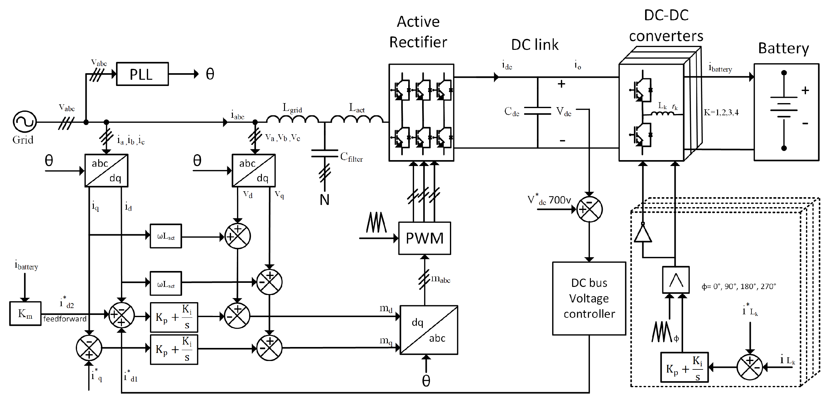
The overall control framework is organized hierarchically to guarantee stable bidirectional power flow, robust DC-link regulation, and strict compliance with grid standards. Figure 2 illustrates the unified architecture, in which inner current controllers for both the AC/DC and DC/DC stages are embedded within outer voltage regulation loops, supported by a phase-locked loop (PLL) for synchronization and a feedforward mechanism for enhanced transient response.

3.1. Inner Current Control Loops

The first layer of the control hierarchy is the inner current regulation. The modeling in Section 2 showed that both the AC and DC sides reduce to first-order plants, making them well suited for PI control. On the grid side, using the equivalent series inductance and resistance of the LCL filter, the plant dynamics of each axis are expressed as:
G i , a c ( s ) = I ( s ) V ( s ) = 1 L s s + R s .
On the battery side, small-signal analysis of the interleaved DC/DC stage yields:
G i , b a t ( s ) = i ^ L ( s ) d ^ ( s ) = V op L s + R L ,
Both plants are compensated by PI controllers of the form C ( s ) = K p + K i / s . The controller parameters are designed via pole-placement to achieve a desired closed-loop response characterized by a natural frequency ω n and damping ratio ζ . The closed-loop transfer function for a system with open-loop L ( s ) = C ( s ) G ( s ) has a characteristic equation of 1 + L ( s ) = 0 . Substituting the plant and controller models yields:
1 + K p , i d c + K i , i d c s V op L s + R = 0 .
Multiplying through by s ( L s + R ) and rearranging terms gives the characteristic equation:
L s 2 + ( R + V op K p , i d c ) s + V op K i , i d c = 0 .
This is equated to the desired second-order characteristic equation s 2 + 2 ζ ω n s + ω n 2 = 0 . Normalizing Equation (39) by dividing by L allows for coefficient comparison:
R + V op K p , i d c L = 2 ζ ω n ,
V op K i , i d c L = ω n 2 .
Solving for the PI gains provides the final design equations:
K p , i d c = 2 ζ ω n L R V op ,
K i , i d c = ω n 2 L V op .
These controllers ensure decoupled d q current regulation on the grid side and precise inductor current tracking on the battery side, directly reflecting the models developed earlier.

3.2. Outer DC-Link Voltage Regulation

The supervisory function of the control system is the DC-link voltage regulation. The plant model for this loop is derived from the nonlinear power balance equation, which is linearized around a nominal operating point ( V d c 0 , I d 0 ). Starting from the power balance:
d d t 1 2 C d c V d c 2 = P a c P b a t .
Assuming the inner current loop forces i d i d and aligning the d q -frame such that P a c 3 2 v d i d , the equation becomes:
C d c V d c d V d c d t = 3 2 v d i d P b a t .
Applying small-signal perturbation ( V d c = V d c 0 + v ^ d c , i d = I d 0 + i ^ d ) and neglecting the product of perturbation terms and the disturbance P b a t yields the linearized model:
C d c V d c 0 d v ^ d c d t 3 2 V d 0 i ^ d .
Taking the Laplace transform gives the simplified plant transfer function:
G v ( s ) = v ^ d c ( s ) i ^ d ( s ) = K v C d c s , where K v = 3 V d 0 2 V d c 0 .
This pure integrator plant motivates the use of a PI regulator:
C v ( s ) = K p , v d c + K i , v d c s ,
which provides proportional action for response speed and integral action for zero steady-state error. The bandwidth of this outer loop is chosen at least one decade below that of the inner current loops to ensure stable cascaded control.

3.3. Grid Synchronization Using PLL

Accurate grid synchronization is essential to align the d q -frame with the grid voltage vector. The PLL design builds directly on the d q model, where proper alignment ensures that v q 0 and hence i d and i q regulate active and reactive power independently. The adopted synchronous reference frame PLL (SRF-PLL) uses a PI controller to regulate the q-component of the grid voltage to zero. The closed-loop transfer function from the actual grid phase θ to the estimated phase θ ^ is given by:
G PLL ( s ) = θ ^ ( s ) θ ( s ) = K p , PLL s + K i , PLL s 2 + K p , PLL s + K i , PLL ,
where K p , PLL and K i , PLL are the PI gains. These parameters are tuned to achieve adequate phase margin (typically > 45 ) for fast dynamic response and robust disturbance rejection under unbalanced grid conditions.

3.4. Feedforward Compensation for Transient Enhancement

The DC-link power balance model also motivates the inclusion of feedforward control to improve transient performance. The goal is to compute the d-axis current required to supply the battery power P b a t V d c i b a t instantaneously. From the active power balance P a c = P b a t and the equation P a c 3 2 v d i d , the feedforward current is:
i d , f f = 2 3 P b a t v d 2 3 V d c i b a t v d ,
where V d c is the DC-link voltage reference. The total d-axis current reference is then:
i d = i d , f b + i d , f f = i d , f b + 2 3 V d c i b a t v d .
Using the reference voltage V d c instead of the measured V d c avoids introducing an algebraic loop. This term immediately compensates for disturbances caused by battery current variations, reducing the burden on the feedback controller.

3.5. Control of the Interleaved DC-DC Converter

For the interleaved converter, the small-signal control-to-inductor-current transfer function identified in the modeling stage is:
G i d ( s ) = i ^ L k ( s ) d ^ k ( s ) = V op L s + R L ,
where V op = V d c in buck mode and V op = V b a t in boost mode. This first-order plant justifies the use of a PI controller for each phase current loop. Using pole-placement tuning for a desired closed-loop bandwidth ω n and damping ratio ζ , the controller gains are:
K p , v d c = 2 ζ ω n L R L V op ,
K i , v d c = ω n 2 L V op .
This design ensures accurate bidirectional current regulation. The interleaving of the phase carriers, phase-shifted by 90 , provides the additional benefit of significant ripple cancellation at the battery terminals.

3.6. Optimization of PI Controllers Using ABC Algorithm

Although the analytical tuning described above guarantees stability and satisfactory transient response, it is sensitive to parameter variations and nonlinearities. To address this limitation and achieve superior performance across the entire operating range, the controller gains are refined using the Artificial Bee Colony (ABC) optimization algorithm, a sophisticated metaheuristic technique inspired by honeybee foraging behavior [39]. Each candidate solution encodes the complete set of PI parameters, including those of the current controllers, voltage regulator, and PLL. The optimization is driven by a multi-objective cost function:
J = α 0 T e V d c 2 ( t ) d t + β 0 T e θ 2 ( t ) d t ,
where e V d c denotes the DC-link voltage error, e θ the phase error of the PLL, and α , β weighting coefficients that balance voltage stability and synchronization accuracy. The ABC-based optimization achieves superior performance compared to purely analytical design, leading to faster settling times, reduced overshoot, and enhanced robustness under a wide range of grid and load conditions.
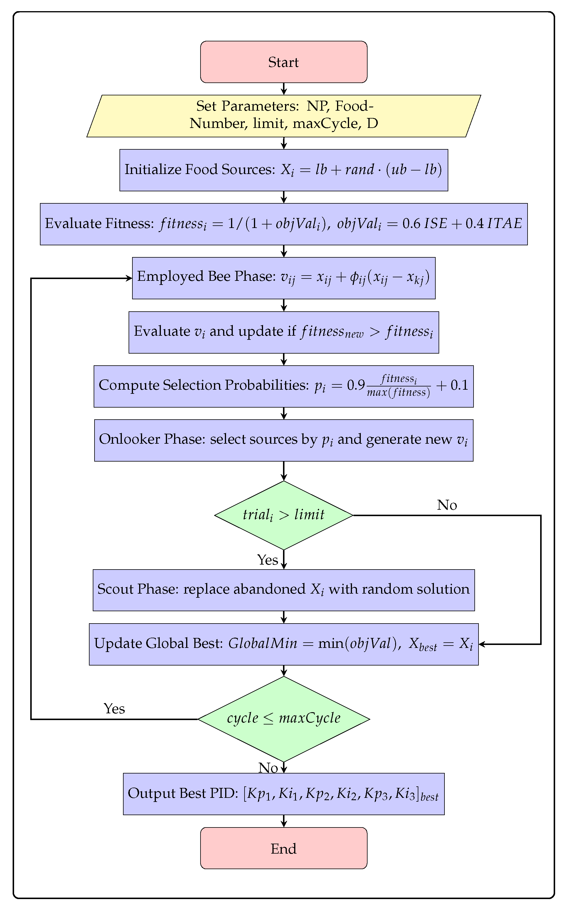
The ABC algorithm implements a population-based optimization strategy that mimics the foraging behavior of honeybee colonies [40]. ABC is particularly advantageous for engineering optimization tasks due to its simplicity, requiring fewer tunable parameters than alternatives like Genetic Algorithms (GA) and Particle Swarm Optimization (PSO), while exhibiting faster convergence and robust exploration-exploitation balance [41,42]. Recent comparative studies in power electronics underscore these benefits. For instance, ABC optimization yielded superior objective function values (e.g., reduced ITAE by up to 20%) and shorter execution times than PSO, for robust control of interlinking converters in hybrid microgrids [43,44]. The complete optimization procedure follows the systematic flowchart shown in Figure 5, which details the iterative process of solution generation, evaluation, and refinement.
The optimization process begins with parameter initialization, where key algorithm parameters such as colony size (NP), food number, abandonment limit, maximum cycles (maxCycle), and problem dimension (D) are defined. The algorithm then proceeds to initialize food sources representing potential solutions using the equation X i = l b + r a n d · ( u b l b ) , where each solution encodes the complete set of PI parameters: x i = [ K p , i d c , K i , i d c , K p , v d c , K i , v d c , K p , PLL , K i , PLL ] .
Each candidate solution undergoes fitness evaluation using the objective function o b j V a l i = 0.6 I S E + 0.4 I T A E , which combines integral squared error and integral time-weighted absolute error metrics to balance rapid response with long-term stability. The fitness is calculated as f i t n e s s i = 1 / ( 1 + o b j V a l i ) , with higher values indicating better solutions.
The employed bee phase conducts local searches around existing solutions using the mutation equation v i j = x i j + ϕ i j ( x i j x k j ) , where ϕ i j is a random number in [−1, 1]. New solutions are evaluated and retained if they exhibit improved fitness. The onlooker bee phase then selects promising solutions probabilistically based on selection probabilities p i = 0.9 f i t n e s s i m a x ( f i t n e s s ) + 0.1 , intensifying the search in regions with higher fitness values.
Solutions that fail to improve beyond the abandonment limit ( t r i a l i > l i m i t ) enter the scout bee phase, where they are replaced with randomly generated solutions to maintain population diversity and prevent premature convergence to local optima. The global best solution is updated after each cycle, and the process iterates until the maximum cycle count is reached. The specific parameters used for the ABC optimization are detailed in Table 3, which were determined through extensive preliminary testing to balance computational efficiency with solution quality.

4. Systematic Design of Circuit Elements and Controller Parameters

Building upon the control-oriented models and design equations established in Section 3, this section presents a systematic procedure for determining both the passive component values and controller parameters of the proposed bidirectional EV fast-charging system. The design process follows a hierarchical approach, beginning with the analytical computation of controller gains using the derived transfer functions and pole-placement techniques, and concluding with refinement through metaheuristic optimization to enhance robustness and performance.
Table 4 summarizes the complete set of system specifications, passive component values, and controller parameters obtained through this systematic design procedure, including both analytically derived and ABC-optimized values.

4.1. Analytical Controller Design

The controller parameters are systematically derived using the mathematical framework developed in Section 3. For the grid-side current control, the plant dynamics G i , a c ( s ) = 1 / ( L a c t s + R ) with L a c t = 0.112 mH and R = 1.0 Ω form the basis for PI controller design. Setting the current loop bandwidth to one-tenth of the switching frequency ( f s w = 10 kHz) yields:
ω i , s w = 2 π f s w 10 6283 rad / s .
Applying the pole-placement design equations K p = ( 2 ζ ω n L R ) / V o p and K i = ( ω n 2 L ) / V o p with ζ = 0.707 and V o p = 339.4 V produces the current controller gains:
K p , i d c = L a c t · ω i , s w R = 0.7027 ,
K i , i d c = R · ω i , s w = 6.283 .
For the DC-link voltage regulation, the plant model G v ( s ) = K v / ( C d c s ) with K v = 3 V d 0 / ( 2 V d c 0 ) guides the controller design. Using V d c = 700 V, C d c = 95.5 mF, E m = 339.4 V, and a desired response time of ( t 1 t 0 ) = 20 ms, the voltage controller gains are calculated as:
K p , v d c = 2 V d c C d c 3 E m ( t 1 t 0 ) = 6.576 ,
K i , v d c = 4131.8 .
The synchronous reference frame PLL design employs the transfer function G PLL ( s ) = ( K p , PLL s + K i , PLL ) / ( s 2 + K p , PLL s + K i , PLL ) with a crossover frequency of ω c = 2 π · 30 rad/s and 45 phase margin. The resulting synchronization gains are:
K p , P L L = ω c V 1 + 0.555 ,
K i , P L L = ω c 2 V 1 + b 43.2 .
For the interleaved DC-DC converter current control, the transfer function G i d ( s ) = V o p / ( L s + r ) with L = 2 mH, r = 2.5 Ω , and V o p = 700 V provides the foundation. Applying the pole-placement technique with ω n = 2000 rad/s and ζ = 0.707 yields the initial analytical values:
K p , d c = 2 ζ ω n L r V o p 4.5 × 10 3 ,
K i , d c = ω n 2 L V o p 11.43 .
These are subsequently refined to the final implemented values through iterative simulation to account for practical implementation constraints:
K p , d c = 0.00785 , K i , d c = 12.26 .

4.2. Optimization-Based Refinement

While the analytical design guarantees stability and satisfactory performance, the controller gains are further refined using the ABC algorithm described in Section 3. The optimization process employs the multi-objective cost function J = α 0 T e V d c 2 ( t ) d t + β 0 T e θ 2 ( t ) d t to balance voltage regulation and synchronization accuracy across the entire operating range. It is crucial to note that the ABC algorithm, while computationally intensive, is executed entirely offline during the system design phase. This ensures that the computational burden of the metaheuristic search is completely decoupled from the real-time operation of the charger. Once the optimal parameter set is identified, the values are fixed and deployed to the digital controller. The resulting ABC-optimized parameters demonstrate superior dynamic performance compared to the purely analytical design, with significantly improved settling times and enhanced robustness to parameter variations, all without introducing any online computational overhead.

5. System Performance Evaluation, Results and Discussion

The performance of the proposed bidirectional fast-charging system was evaluated through time-domain simulations using the component values and controller parameters derived in Section 4. This comprehensive assessment examines the system’s performance across multiple operational scenarios and control strategies, culminating in a detailed comparative analysis that quantifies the progressive improvements achieved through each design iteration. The assessment focuses on three critical aspects: the four-phase interleaved buck–boost converter’s bidirectional operation, the active rectifier’s grid-interfacing capabilities, and the overall system enhancement achieved through Artificial Bee Colony (ABC) optimization.
The four-phase interleaved bidirectional buck–boost converter demonstrates exceptional performance in both charging and discharging modes. The converter achieves high efficiency exceeding 96% in both power flow directions, validating the effectiveness of the interleaved structure in distributing current evenly across phases and reducing individual component stress. As summarized in Table 5, the converter exhibits excellent transient performance with settling times of 0.323 s in charging mode and remarkably fast 4.292 ms in discharging mode. The interleaving technique proves highly effective, reducing the net battery current ripple to only 0.327 A in charging and 0.554 A in discharging operation—representing less than 1.8% of the rated current. This significant ripple cancellation, achieved through the 90° phase-shifted operation, minimizes stress on battery cells and reduces DC-link capacitance requirements.
Figure 6 illustrates the smooth current sharing among the four phases, with each carrying approximately one quarter of the total current. The uniform distribution confirms the effectiveness of the phase management strategy and validates the analytical current control design using the parameters from Table 4.

5.1. Active Rectifier Performance Evolution

The active rectifier’s performance was evaluated across multiple control strategies to assess the progressive improvements achieved through design refinement. The comparative analysis reveals significant enhancements in transient response and power quality.

5.1.1. Baseline Performance Without Feedforward

The initial configuration with analytically tuned PI controllers demonstrated satisfactory steady-state performance but exhibited substantial transient limitations. As shown in Table 6, this configuration suffered from DC-link voltage overshoot of 138.17% and undershoot of 71.71% during charging transitions, with extended settling times of 920 ms. While current THD remained within acceptable limits (1.77% in charging), the significant transient deviations revealed fundamental limitations of the feedback-only control structure.

5.1.2. Enhanced Performance with Feedforward Compensation

The introduction of feedforward compensation marked a significant improvement in system dynamics. While steady-state performance metrics remained excellent, the feedforward path substantially reduced the corrective burden on the voltage regulator. As quantified in Table 6, DC-link voltage ripple was reduced to 0.161 V during discharging, and current THD improved to 1.63% in charging operation.
These findings demonstrate that while the active rectifier, governed by analytically derived PI gains, achieves commendable steady-state performance, it is prone to considerable DC-link excursions under rapid transient conditions. The judicious addition of a model-based feedforward path ( K m ) not only sustains these steady-state indices but also substantially ameliorates transient deviations and alleviates the corrective burden on the control system, as evidenced by the comparative data in Table 6 and the waveform contrasts in Figure 7, Figure 8 and Figure 9. These outcomes provide compelling justification for the adoption of feedforward compensation to enhance system robustness and motivate the use of ABC for controllers’ parameters optimization.

5.2. Optimized System with ABC Algorithm

The analytical tuning of the PI regulators, together with the inclusion of the feedforward term K m , provided a solid foundation for stable operation of the active rectifier and DC-link interface. However, the system continued to exhibit limitations under rapid load transients and bidirectional power transitions. Notably, peak overshoot, non-negligible settling times, and sub-optimal coordination between the nested current and voltage control loops persisted. Such characteristics can compromise both reliability and efficiency in high-power fast-charging applications, motivating the deployment of a more sophisticated optimization framework capable of balancing multiple performance objectives beyond the reach of conventional analytical methods.
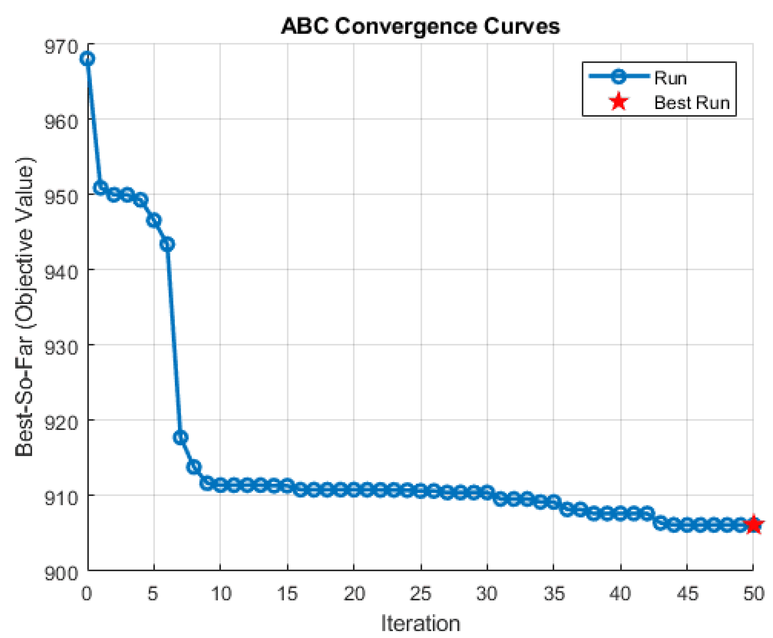
The Artificial Bee Colony (ABC) algorithm was adopted as the optimization tool owing to its robust global search capability, its avoidance of premature convergence, and its efficiency in handling nonlinear, multi-dimensional tuning problems. Each candidate solution in the ABC framework represented a complete set of PI gains for the inner current loop, the DC-link voltage controller, and the phase-locked loop. The convergence profile in Figure 10 illustrates the efficiency of the algorithm, with stable solutions consistently achieved after a relatively small number of iterations.
The optimized parameters obtained through this process are presented in Table 4. Compared with the analytically derived gains, the ABC-tuned values represent a coordinated adjustment across all control layers, yielding improved dynamic performance without sacrificing steady-state robustness. Table 7 reports the corresponding performance indices. With the ABC optimization algorithm, the DC-link ripple was reduced to 0.2002 V in charging and 0.08224 V in discharging operation, while the grid current THD was maintained at 1.27% and 0.59%, respectively. Overshoot decreased from 26.5% to 24.57% in charging mode and from 1.91% to 1.24% in discharging mode, while undershoot was eliminated entirely. The DC-link settling time in charging operation improved to 238 ms, reflecting significantly enhanced damping and faster restoration to steady-state conditions.
Figure 11 and Figure 12 provide further insight into the impact of ABC optimization. The DC-link voltage trajectories demonstrate substantially smaller deviations following step changes, with rapid stabilization requiring less corrective action from the voltage regulator. This effect reduces capacitor stress and alleviates transient energy swings across the power devices. Similarly, grid current responses exhibit improved alignment with their sinusoidal references, with fewer oscillations and reduced corrective burden on the d-axis current regulator. These improvements, although accompanied by marginal changes in steady-state THD, directly influence thermal loading, device stress, and long-term system reliability-factors of central importance in practical fast-charging deployments.
Against the analytically tuned baseline controllers, ABC yielded notable reductions in ripple, overshoot, and undershoot, alongside meaningful improvements in settling time. When evaluated against the feedforward-enhanced configuration, the benefits were more nuanced but remained operationally significant, particularly in reducing discharge-mode ripple and in eliminating undershoot. These refinements confirm that ABC tuning enhances the system’s resilience to worst-case transient events while preserving compliance with grid-side harmonic standards.
Visual validation through Figure 13, Figure 14 and Figure 15 provides critical insights into the system’s performance enhancements across different control strategies. Figure 13 demonstrates superior grid synchronization under ABC optimization, showing near-perfect alignment between grid voltage and current waveforms with a phase error reduction. The current waveforms exhibit significantly reduced harmonic distortion and improved sinusoidal quality compared to the analytical and feedforward cases.
Figure 14 presents a comparative analysis of DC-link voltage behavior during the critical charging-to-discharging transition. The ABC-optimized controller reduces the maximum voltage deviation to 24.57% of nominal value, compared to 138.14% for the feedforward case and 138.17% for the baseline. More notably, the settling time shows remarkable improvement from 920 ms (baseline) to 238 ms (ABC-optimized), representing a 74.1% reduction in recovery duration. The voltage trajectory exhibits critically damped characteristics without overshoot or undershoot, confirming the optimized damping ratio achieved through the ABC algorithm.
Figure 15 comprehensively illustrates the battery-side dynamics during bidirectional operation. The battery current waveform shows a settling time reduction to 238 ms with complete elimination of the overshoot present in previous configurations. The state-of-charge profile demonstrates smooth transitions between charging and discharging modes, while the duty cycle variations indicate stable and predictable converter operation throughout the power reversal process.
The ABC optimization framework successfully reconciles competing objectives by deriving a coherent set of control gains that achieve simultaneous improvements in dynamic response, stability margins, and power quality, addressing fundamental challenges in high-power bidirectional charging systems, particularly their vulnerability to rapid power flow transitions and grid disturbances. By reducing DC-link excursions, improving current-tracking fidelity, and minimizing transient corrective effort, the optimized controllers enhance both efficiency and durability while maintaining robust steady-state performance, with the algorithm’s consistent delivery of high-quality solutions within limited iterations demonstrating its practical suitability for advanced EV fast-charging applications.

5.3. Subsystem-Level Signal Verification

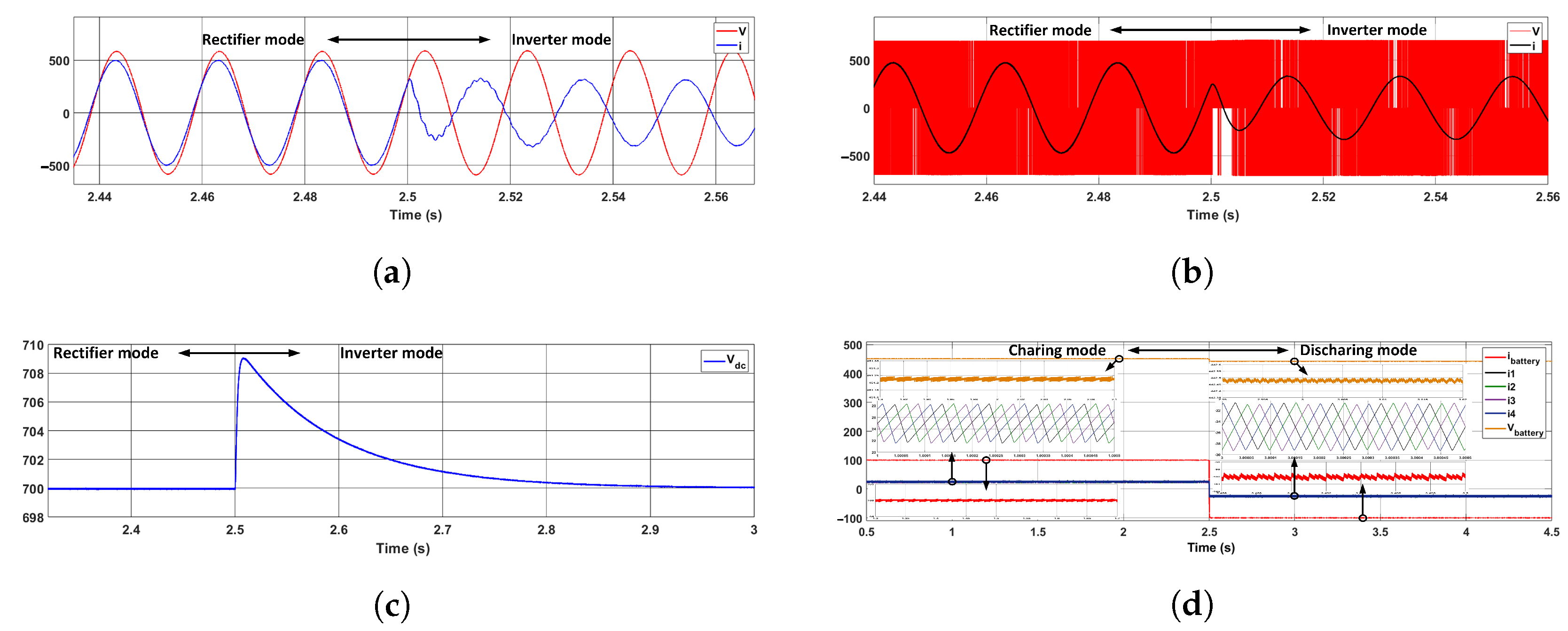
Subsystem-level verification provides a comprehensive assessment of the proposed control architecture and power-stage topology, confirming that both steady-state power quality and transient performance meet the requirements for high-power bidirectional charging. The analysis examines four primary domains: (i) grid-side currents at the point of common coupling and across the LCL filter, (ii) DC-link voltage dynamics during transitions between charging and discharging operation modes, (iii) battery-side currents in the four-phase interleaved buck–boost stage, and (iv) controller performance during transient events. Quantitative validation relies on Table 8 and Table 9 and time-domain signals depicted in Figure 16.
The DC-link demonstrates excellent steady-state stability and well-defined transient behavior. Voltage ripple measures 0.20 V in the charging operation mode and 0.08 V in the discharging operation mode, corresponding to 0.029% and 0.011% of the nominal 700 V DC-link voltage. During transitions, the DC-link exhibits an overshoot of 24.57% with a settling time of 238 ms in the charging operation mode, whereas the discharging operation mode presents minimal overshoot (1.24%) with near-instantaneous settling. These behaviors are illustrated in Figure 16c, showing a critically damped voltage response closely aligned with the tabulated metrics. The reduction in ripple amplitude from charging to discharging operation modes mitigates RMS stress on the DC-link capacitor, improving both component lifespan and overall system reliability.
Grid-side currents satisfy all relevant standards, with total THD of 1.127% (charging operation mode) and 0.59% (discharging operation mode), well below the 5% IEEE-519 limit. Per-phase THD remains under 0.62% and 0.31% in charging and discharging operation modes, respectively, with unity power factor maintained in both modes. Figure 16a illustrates the three-phase input currents at the LCL filter, whereas Figure 16b shows filtered sinusoidal currents precisely aligned with the grid voltage, confirming the effectiveness of the LCL filter and high-bandwidth dq-current control.
Battery-side verification highlights the efficiency of the four-phase interleaved buck–boost converter. Single-phase ripple measures 6.516 A (charging operation mode) and 8.625 A (discharging operation mode), while the aggregated battery current ripple is reduced to 0.33 A and 0.55 A, respectively. These values correspond to cancellation factors of 19.7× in charging operation mode and 15.7× in discharging operation mode, surpassing the theoretical fourfold improvement expected from ideal interleaving. The resulting battery current waveform, shown in Figure 16d, exhibits a smooth, low-amplitude envelope, reducing electrochemical stress and minimizing filter requirements. A uniform switching frequency of 10 kHz across all operating conditions confirms compliance with thermal and loss constraints.
Controller performance, enhanced by feedforward compensation and ABC optimization, is verified through transient response evaluation. The DC-link settling time of 238 ms in the charging operation mode represents a 74% improvement over the 920 ms baseline, while discharging operation mode transitions stabilize nearly instantaneously. Figure 16c demonstrates a critically damped response, with rapid initial compensation followed by smooth feedback correction. Inner current control loops maintain fast, balanced distribution across all phases, as seen in Figure 16d, confirming robustness under transient load conditions.

6. Comparative Analysis with State-of-the-Art Topologies and Controllers

To rigorously situate the contributions of this work within the current research landscape, a detailed comparative analysis with recent and seminal bidirectional EV fast-charging systems is presented. The comparison is structured into two parts: Table 10 focuses on grid-side AC/DC converter systems, while Table 11 examines battery-side DC/DC converter topologies. This bifurcation allows for a clear evaluation of the proposed system’s performance against specialized solutions in each domain, as well as integrated architectures.
Table 10 summarizes the performance of key bidirectional AC/DC systems from the literature against the proposed unified system. The comparison metrics include topology, control strategy, critical performance indicators like Total Harmonic Distortion (THD) and transient response, power rating, and identified limitations.
Table 10. Comparative Analysis of Bidirectional AC/DC Converter Systems for EV Fast Charging.
Ref.YearTopologyControl MethodKey PerformancePowerLimitations
[22]2005Active rectifier + LCLPI cascadeTHD ∼3%, low harmonics4.1 kWPassive damping losses, no V2G test
[16]2009VSC + LCL filterVOC + active dampingTHD <5%, fast response50 kVAGrid distortion sensitivity, no battery link
[47]2014Single-phase AC/DCDual PI + feedforwardTHD ∼4.3%, PF 0.991Proto.Single-phase only, zero-crossing distortion
[29]20173-phase VSCUnified droop18 ms settling, unity PF2 kWAircraft-specific, tuning-dependent
[23]20203-phase AC/DC + L-filterDouble PI + feedforwardTHD 1.1–2.1%, 178–260 ms settling80 kWPoor low-power behavior, complex tuning
[48]20233-phase VSC + LCLVOC + PI + observerTHD 2.62–2.71%, stable16 kVAObserver sensitivity, limited scalability
[49]20253-phase PWM + LCLSMC + PITHD ∼4.5%, 130/60 ms settlingkW-scaleHigh complexity, no discharging validation
This work20253-phase VSC + LCL + 4-phase IBBCABC-optimized PI + FFTHD 0.59%, zero V2G settling, 0.08–0.20 V ripple50 kWHigher component count, global optimization effort
As evidenced in Table 10, the proposed system demonstrates superior grid current quality, achieving a THD of 0.59% which is significantly lower than the 2.6% to 5.7% reported in other works. Furthermore, the transient performance, marked by zero settling time during V2G transitions and minimal DC-link voltage ripple (0.08–0.20 V), surpasses the slower responses (60–260 ms) and larger ripples (e.g., 1.8–2 V in [23]) of existing systems. Unlike several compared works [16,22,29,47], the proposed architecture is validated for full bidirectional operation at a high power level (50 kW), addressing a common limitation in the literature.
A separate comparison for the DC/DC stage, provided in Table 11, highlights the advantages of the interleaved approach for battery interface. The proposed DC/DC stage, as shown in Table 11, maintains high efficiency (>95%) at a much higher power rating (50 kW) compared to several low-power prototypes [50,51]. It achieves excellent battery current ripple suppression (<0.6 A) without the magnetic complexity of coupled inductors. While [15] reports a similar high efficiency at 100 kW, that work is limited to the DC/DC stage alone, whereas the proposed system offers a complete, integrated solution. The key advantage of the proposed system lies in its holistic and optimized integration of both conversion stages. While many referenced works excel in one specific area (e.g., fast response in [29] or high DC/DC efficiency in [15]), they often lack a complete, high-performance bidirectional solution. The proposed architecture delivers record-low grid current distortion (THD of 0.59%) with outstanding dynamic behavior, including minimal DC-link ripple and rapid recovery during demanding V2G events. At the battery interface, it maintains high efficiency through effective ripple cancellation, even at scalable power levels. These performance gains are complemented by strong system-level robustness, enabled by a unified metaheuristic-optimized control strategy that avoids the tuning burden of complex advanced controllers while surpassing conventional PI methods. Overall, the comparative results confirm that the proposed solution marks a substantial advancement in high-performance, reliable, fully bidirectional off-board EV fast-charging infrastructure.
Table 11. Comparative Analysis of Bidirectional DC/DC Converter Systems for EV Fast Charging.
Ref.YearTopologyControl MethodKey PerformancePowerLimitations
[15]20073-phase interleavedZVS soft-switching∼98% efficiency, high density100 kWNo grid interface, DC/DC only
[51]20183-phase interleaved + coupled inductorsPhase-decoupled controlLow ripple, fast transient response180 WParameter sensitivity, complex structure
[50]2020Multiphase interleaved + coupled inductorsPhase-shifted PWM>98% efficiency, low ripple4.5 kWHard switching, complex magnetics
This work20254-phase interleaved bidirectional buck–boostOptimized PI current control>95% efficiency, <0.6 A battery ripple50 kWRequires multi-phase gate drivers

7. Conclusions

This paper has presented a comprehensive, system-level study on the design, optimization, and performance evaluation of a bidirectional off-board EV fast-charging system. The work was motivated by the observation that while the constituent power converter stages are well-understood, their integrated operation presents system-level challenges, particularly in control dynamics and transient performance, that are not fully resolved in the existing literature. Our systematic approach began with the development of a holistic dynamic model of the dual-stage system, which formed the basis for a unified hierarchical control strategy. The key to achieving superior performance lies in addressing the system-level coupling, primarily through two mechanisms: (1) the implementation of a battery current feedforward compensation to decouple the DC-link dynamics during abrupt load changes, and (2) the application of the Artificial Bee Colony (ABC) algorithm for the global optimization of all PI controller gains across the entire system.
The simulation results unequivocally demonstrate the value of this system-level optimization approach. The progressive refinement from an analytically tuned baseline to a feedforward-augmented system, and finally to the ABC-optimized controller, yielded substantial performance gains. Specifically, the optimized system achieved a 74% reduction in DC-link voltage settling time (from 920 ms to 238 ms) during critical charging-to-discharging transitions, while simultaneously eliminating undershoot and significantly reducing overshoot. Furthermore, the system maintained excellent steady-state performance, with grid current THD consistently below 1.2% and near-perfect power factor, ensuring compliance with power quality standards. On the battery side, the interleaved DC/DC converter effectively minimized current ripple to less than 0.55 A, reducing stress on the battery pack.
This work underscores a critical insight for the development of advanced EV charging infrastructure: significant performance improvements can be unlocked not necessarily through novel circuit topologies, but through the rigorous, system-wide co-design and optimization of control strategies for existing, proven architectures.

Limitations and Future Work

This study is based on simulation models, which, while detailed, cannot fully capture all non-idealities of a physical system, such as component tolerances, parasitic elements, and electromagnetic interference. The primary limitation is therefore the lack of experimental validation. The logical next step is to implement the optimized control laws on a real-time controller (e.g., an FPGA or DSP) and validate the performance using a hardware prototype or a power-hardware-in-the-loop (PHIL) setup. Furthermore, the computational burden of the ABC algorithm is only relevant for the offline design phase; future work could explore the implementation of these pre-optimized gains with adaptive control techniques to maintain performance under component aging and parameter variations.

Author Contributions

Conceptualization, A.H., J.M. and Z.Z.; Methodology, A.H.; Software, A.H.; Validation, A.H. and Z.Z.; Formal Analysis, A.H.; Investigation, A.H.; Data Curation, A.H.; Writing—Original Draft Preparation, A.H.; Writing—Review & Editing, A.H., J.M. and Z.Z.; Supervision, Z.Z. All authors have read and agreed to the published version of the manuscript.

Funding

This research received no specific grant from any funding agency in the public, commercial, or not-for-profit sectors.

Data Availability Statement

The original contributions presented in this study are included in the article. Further inquiries can be directed to the corresponding author.

Conflicts of Interest

The authors declare no conflict of interest.

References

  1. Zhao, A.P.; Li, S.; Xie, D.; Wang, Y.; Li, Z.; Hu, P.J.H.; Zhang, Q. Hydrogen as the nexus of future sustainable transport and energy systems. Nat. Rev. Electr. Eng. 2025, 2, 447–466. [Google Scholar] [CrossRef]
  2. Liu, Z.; Zhu, L.; Hou, K.; Zhou, Y.; Zhao, R.; Jia, H. A State-similarity-based fast reliability assessment for power systems with variations of generation and load. IEEE Trans. Power Syst. 2024, 1–13. [Google Scholar] [CrossRef]
  3. Yoro, K.O.; Daramola, M.O. CO2 emission sources, greenhouse gases, and the global warming effect. In Advances in Carbon Capture; Elsevier: Amsterdam, The Netherlands, 2020; pp. 3–28. [Google Scholar]
  4. Kabir, M.; Habiba, U.E.; Khan, W.; Shah, A.; Rahim, S.; De los Rios-Escalante, P.R.; Farooqi, Z.U.R.; Ali, L.; Shafiq, M. Climate change due to increasing concentration of carbon dioxide and its impacts on environment in 21st century: A mini review. J. King Saud-Univ.-Sci. 2023, 35, 102693. [Google Scholar] [CrossRef]
  5. Habib, S.; Khan, M.M.; Abbas, F.; Sang, L.; Shahid, M.U.; Tang, H. A comprehensive study of implemented international standards, technical challenges, impacts and prospects for electric vehicles. IEEE Access 2018, 6, 13866–13890. [Google Scholar] [CrossRef]
  6. Manousakis, N.M.; Karagiannopoulos, P.S.; Tsekouras, G.J.; Kanellos, F.D. Integration of renewable energy and electric vehicles in power systems: A review. Processes 2023, 11, 1544. [Google Scholar] [CrossRef]
  7. Masrur, M.A.; Skowronska, A.G.; Hancock, J.; Kolhoff, S.W.; McGrew, D.Z.; Vandiver, J.C.; Gatherer, J. Military-based vehicle-to-grid and vehicle-to-vehicle microgrid—System architecture and implementation. IEEE Trans. Transp. Electrif. 2017, 4, 157–171. [Google Scholar] [CrossRef]
  8. Habib, S.; Khan, M.M.; Abbas, F.; Tang, H. Assessment of electric vehicles concerning impacts, charging infrastructure with unidirectional and bidirectional chargers, and power flow comparisons. Int. J. Energy Res. 2018, 42, 3416–3441. [Google Scholar] [CrossRef]
  9. Savio Abraham, D.; Verma, R.; Kanagaraj, L.; Giri Thulasi Raman, S.R.; Rajamanickam, N.; Chokkalingam, B.; Marimuthu Sekar, K.; Mihet-Popa, L. Electric vehicles charging stations’ architectures, criteria, power converters, and control strategies in microgrids. Electronics 2021, 10, 1895. [Google Scholar] [CrossRef]
  10. Chen, T.; Zhang, X.P.; Wang, J.; Li, J.; Wu, C.; Hu, M.; Bian, H. A review on electric vehicle charging infrastructure development in the UK. J. Mod. Power Syst. Clean Energy 2020, 8, 193–205. [Google Scholar] [CrossRef]
  11. Vagropoulos, S.I.; Balaskas, G.A.; Bakirtzis, A.G. An investigation of plug-in electric vehicle charging impact on power systems scheduling and energy costs. IEEE Trans. Power Syst. 2016, 32, 1902–1912. [Google Scholar] [CrossRef]
  12. Singh, A.K.; Pathak, M.K. Single-phase bidirectional ac/dc converter for plug-in electric vehicles with reduced conduction losses. IET Power Electron. 2018, 11, 140–148. [Google Scholar] [CrossRef]
  13. Dini, P.; Saponara, S.; Colicelli, A. Overview on battery charging systems for electric vehicles. Electronics 2023, 12, 4295. [Google Scholar] [CrossRef]
  14. Mastoi, M.S.; Zhuang, S.; Munir, H.M.; Haris, M.; Hassan, M.; Usman, M.; Bukhari, S.S.H.; Ro, J.S. An in-depth analysis of electric vehicle charging station infrastructure, policy implications, and future trends. Energy Rep. 2022, 8, 11504–11529. [Google Scholar] [CrossRef]
  15. Zhang, J.; Lai, J.S.; Kim, R.Y.; Yu, W. High-power density design of a soft-switching high-power bidirectional dc–dc converter. IEEE Trans. Power Electron. 2007, 22, 1145–1153. [Google Scholar] [CrossRef]
  16. Jalili, K.; Bernet, S. Design of LCL filters of active-front-end two-level voltage-source converters. IEEE Trans. Ind. Electron. 2009, 56, 1674–1689. [Google Scholar] [CrossRef]
  17. Zhou, Z. Unity Power Factor Active Rectifier and DC Bus Controller. Ph.D. Thesis, University of Sussex, Brighton, UK, 2003. [Google Scholar]
  18. Uppara, R.; Priya, S. Analysis of Interleaved Bidirectional DC/DC Converter for Battery Charging & Discharging Applications. In Proceedings of the 2024 International Conference on Smart Systems for applications in Electrical Sciences (ICSSES), Tumakuru, India, 3–4 May 2024; pp. 1–6. [Google Scholar]
  19. Singh, B.; Kushwaha, R. A PFC based EV battery charger using a bridgeless isolated SEPIC converter. IEEE Trans. Ind. Appl. 2019, 56, 477–487. [Google Scholar] [CrossRef]
  20. Ertekin, D. ARVIN converter: A bidirectional DC/DC converter for grid-connected G2V/V2G energy storage and electrification approaches. Electr. Eng. 2024, 106, 5485–5505. [Google Scholar] [CrossRef]
  21. Esfahani, A.G.; Adib, E. Very high step-down coupled inductor two-phase buck converter with single magnetic element and inherent clamp voltage capability. IET Power Electron. 2024, 17, 640–648. [Google Scholar] [CrossRef]
  22. Liserre, M.; Blaabjerg, F.; Hansen, S. Design and control of an LCL-filter-based three-phase active rectifier. IEEE Trans. Ind. Appl. 2005, 41, 1281–1291. [Google Scholar] [CrossRef]
  23. Han, J.; Zhou, X.; Lu, S.; Zhao, P. A Three-Phase Bidirectional Grid-Connected AC/DC Converter for V2G Applications. J. Control Sci. Eng. 2020, 2020, 8844073. [Google Scholar] [CrossRef]
  24. Zmood, D.N.; Holmes, D.G. Stationary frame current regulation of PWM inverters with zero steady-state error. IEEE Trans. Power Electron. 2003, 18, 814–822. [Google Scholar] [CrossRef]
  25. Golestan, S.; Freijedo, F.D.; Guerrero, J.M. A systematic approach to design high-order phase-locked loops. IEEE Trans. Power Electron. 2014, 30, 2885–2890. [Google Scholar] [CrossRef]
  26. Abdalgader, I.A.; Kivrak, S.; Özer, T. Power performance comparison of SiC-IGBT and Si-IGBT switches in a three-phase inverter for aircraft applications. Micromachines 2022, 13, 313. [Google Scholar] [CrossRef]
  27. Vishnuram, P.; Narayanamoorthi, R.; Suresh, P.; Vijayakumar, K.; Bajaj, M.; Khurshaid, T.; Nauman, A.; Kamel, S. A comprehensive review on EV power converter topologies charger types infrastructure and communication techniques. Front. Energy Res. 2023, 11, 1103093. [Google Scholar] [CrossRef]
  28. Umegami, H.; Harada, T.; Nakahara, K. Performance Comparison of Si IGBT and SiC MOSFET Power Module Driving IPMSM or IM under WLTC. World Electr. Veh. J. 2023, 14, 112. [Google Scholar] [CrossRef]
  29. Zheng, X.; Gao, F.; Ali, H.; Liu, H. A droop control based three phase bidirectional AC-DC converter for more electric aircraft applications. Energies 2017, 10, 400. [Google Scholar] [CrossRef]
  30. Mounica, V.; Obulesu, Y. A comprehensive review on non-isolated bidirectional dc-dc converter topologies for electric vehicle application. In Proceedings of the International Conference on Automation, Signal Processing, Instrumentation and Control, Vellore, India, 27–28 February 2020; Springer: Berlin/Heidelberg, Germany, 2020; pp. 2097–2108. [Google Scholar]
  31. Prabhala, V.A.K.; Fajri, P.; Gouribhatla, V.S.P.; Baddipadiga, B.P.; Ferdowsi, M. A DC–DC converter with high voltage gain and two input boost stages. IEEE Trans. Power Electron. 2015, 31, 4206–4215. [Google Scholar] [CrossRef]
  32. Middlebrook, R.D.; Cuk, S. A general unified approach to modelling switching-converter power stages. In Proceedings of the 1976 IEEE Power Electronics Specialists Conference, Cleveland, OH, USA, 8–10 June 1976; pp. 18–34. [Google Scholar]
  33. Erickson, R.W.; Maksimovic, D. Fundamentals of Power Electronics; Springer Science & Business Media: Berlin/Heidelberg, Germany, 2007. [Google Scholar]
  34. Qi, Q.; Ghaderi, D.; Guerrero, J.M. Sliding mode controller-based switched-capacitor-based high DC gain and low voltage stress DC-DC boost converter for photovoltaic applications. Int. J. Electr. Power Energy Syst. 2021, 125, 106496. [Google Scholar] [CrossRef]
  35. Mohan, N.; Undeland, T.M.; Robbins, W.P. Power Electronics: Converters, Applications, and Design; John wiley & sons: Hoboken, NJ, USA, 2003. [Google Scholar]
  36. Beşkardeş, A.; Hameş, Y.; Kaya, K. A comprehensive review on fuzzy logic control systems for all, hybrid, and fuel cell electric vehicles. Soft Comput. 2024, 28, 8183–8221. [Google Scholar] [CrossRef]
  37. Hakam, Y.; Gaga, A.; Tabaa, M.; El Hadadi, B. Enhancing electric vehicle charger performance with synchronous boost and model predictive control for vehicle-to-grid integration. Energies 2024, 17, 1787. [Google Scholar] [CrossRef]
  38. Hao, X.; Chen, Y.; Wang, H.; Wang, H.; Meng, Y.; Gu, Q. A V2G-oriented reinforcement learning framework and empirical study for heterogeneous electric vehicle charging management. Sustain. Cities Soc. 2023, 89, 104345. [Google Scholar] [CrossRef]
  39. Karaboga, D.; Basturk, B. A powerful and efficient algorithm for numerical function optimization: Artificial bee colony (ABC) algorithm. J. Glob. Optim. 2007, 39, 459–471. [Google Scholar] [CrossRef]
  40. Saleh, R.A.; Akay, R. Artificial bee colony algorithm with directed scout. Soft Comput. 2021, 25, 13567–13593. [Google Scholar] [CrossRef]
  41. Khan, M.A.; Li, X.; Yousaf, M.Z.; Mustafa, A.; Wei, M. Metaheuristic Based Solution for the Non-Linear Controller of the Multiterminal High-Voltage Direct Current Networks. Energies 2021, 14, 1578. [Google Scholar] [CrossRef]
  42. Fathy, A.; Kassem, A.; Zaki, Z.A. A robust artificial bee colony-based load frequency control for hydro-thermal interconnected power system. Sustainability 2022, 14, 13569. [Google Scholar] [CrossRef]
  43. Mahboob Ul Hassan, S.; Ramli, M.A.; Milyani, A.H. Robust load frequency control of hybrid solar power systems using optimization techniques. Front. Energy Res. 2022, 10, 902776. [Google Scholar] [CrossRef]
  44. Singh, S.; Gao, D.W. Comparison amongst Lagrange, firefly, and ABC algorithms for low-noise economic dispatch and reactive power compensation in islanded microgrids. Energies 2023, 16, 5119. [Google Scholar] [CrossRef]
  45. IEEE Std 519-1992; IEEE Recommended Practices and Requirements for Harmonic Control in Electrical Power Systems. Institute of Electrical and Electronics Engineers, Inc.: New York, NY, USA, 1993; p. 1.
  46. IEEE Std 519-2022 (Revision of IEEE Std 519-2014); IEEE Standard for Harmonic Control in Electric Power Systems. IEEE: New York, NY, USA, 2022; pp. 1–31. [CrossRef]
  47. Su, M.; Li, H.; Sun, Y.; Xiong, W. A high-efficiency bidirectional AC/DC topology for V2G applications. J. Power Electron. 2014, 14, 899–907. [Google Scholar] [CrossRef]
  48. Tasnim, M.N.; Ahmed, T.; Dorothi, M.A.; Ahmad, S.; Shafiullah, G.; Ferdous, S.; Mekhilef, S. Voltage-oriented control-based three-phase, three-leg bidirectional AC–DC converter with improved power quality for microgrids. Energies 2023, 16, 6188. [Google Scholar] [CrossRef]
  49. Hisar, C.; Balta, G.; Sefa, I.; Altin, N. Sliding Mode-Based Active Damping Control of LCL-Filtered Three-Phase PWM Rectifier. Arab. J. Sci. Eng. 2025, 50, 17845–17862. [Google Scholar] [CrossRef]
  50. Mayer, R.; El Kattel, M.B.; Oliveira, S.V.G. Multiphase interleaved bidirectional DC/DC converter with coupled inductor for electrified-vehicle applications. IEEE Trans. Power Electron. 2020, 36, 2533–2547. [Google Scholar] [CrossRef]
  51. Pan, T.; Wang, Y.; Qu, Z.; Tao, W. Topology optimisation and current sharing strategy of interleaved bidirectional dc/dc converter with coupling technique. IET Power Electron. 2018, 11, 2470–2480. [Google Scholar] [CrossRef]
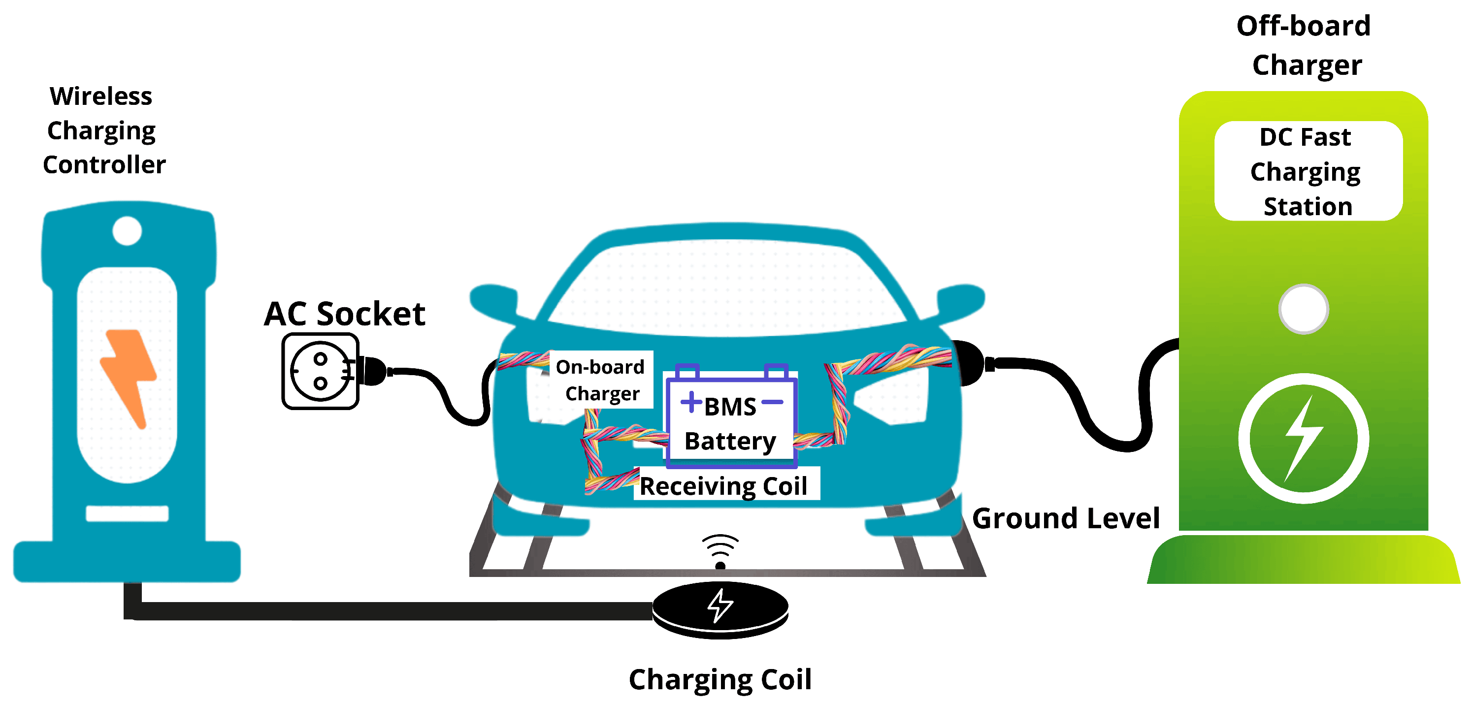
Figure 1. Representative off-board charging architecture supporting bidirectional energy transfer.
Energies 18 05913 g001
Figure 2. Unified Control Architecture for Grid-Connected Three-Phase Bidirectional Conversion and Multi-Phase Interleaved DC Power Processing.
Energies 18 05913 g002
Figure 3. Proposed topology of the bidirectional EV charger system, integrating a three-phase AC/DC active rectifier with an LCL filter and a four-phase interleaved bidirectional DC/DC converter.
Energies 18 05913 g003
Figure 4. Four-phase interleaved bidirectional buck/boost converter connected to the battery.
Energies 18 05913 g004
Figure 5. Flowchart of the ABC Algorithm.
Energies 18 05913 g005
Figure 6. Battery current waveforms during G2V and V2G operation.
Energies 18 05913 g006
Figure 7. DC-link voltage response without feedforward compensation.
Energies 18 05913 g007
Figure 8. DC-link voltage response with feedforward compensation.
Energies 18 05913 g008
Figure 9. Grid current and voltage response with analytically tuned controller (with feedforward).
Energies 18 05913 g009
Figure 10. Convergence curve of ABC algorithm.
Energies 18 05913 g010
Figure 11. DC-link voltage and current response with feedforward and ABC Optimization.
Energies 18 05913 g011
Figure 12. Grid current and voltage responses of the proposed bidirectional converter. shows the overall dynamic behavior under controllers enhanced by feedforward compensation and ABC optimization.
Energies 18 05913 g012
Figure 13. Grid Voltage and Current Waveforms Demonstrating Phase Synchronization under ABC Optimization.
Energies 18 05913 g013
Figure 14. Comparative DC-Link Voltage V d c ( V b a s e , V k m , and V A B C ) Response during G2V–V2G Transition: Analytical, Feedforward, and ABC-Optimized Controllers.
Energies 18 05913 g014
Figure 15. Battery-Side Dynamics: Voltage, Current, State-of-Charge, and Duty Cycle Profiles during Bidirectional Operation.
Energies 18 05913 g015
Figure 16. Sequence of input/output signals across subsystems with detailed zoom-in of LCL filter phases. (a) Grid 3-phase (Input of LCL Filter), (b) After LCL (Output of LCL/Input of Active Rectifier), (c) DC link (Output of Active Rectifier/Input of Buck–Boost), (d) Buck–Boost Output (Output of Buck–Boost).
Energies 18 05913 g016
Table 1. Critical Analysis of the State-of-the-Art in Bidirectional EV Charging Systems.
Research FocusKey AdvancementsPersistent Limitations
Power TopologiesSoft-switching converters [15], interleaved DC-DC designs [18], active front-end rectifiers [19], and advanced bidirectional DC-DC converters (e.g.,common-ground quadratic SEPIC [20] and coupled-inductor two-phase buck [21])Isolated component optimization; lack of co-design leading to DC-link stability issues during power flow transitions; limited exploration of system-level integration for novel high-gain topologies.
Grid InterfaceLCL filter designs [16,22], harmonic mitigation techniques [23]Performance analysis under idealized grid conditions, neglecting real-world transients and imbalances
Control StrategiesCascaded PI control [17], voltage-oriented control(VOC) [24], synchronous reference frame phase-locked loops(SRF-PLL) [25]Sluggish transient response; insufficient exploration of advanced, coordinated multi-loop tuning methods
System IntegrationBidirectional power flow capability [14], V2G service provisionIndependent subsystem optimization; absence of a unified control framework addressing dynamic cross-stage interactions
Table 2. Symbols and Parameters Extracted from Notes.
SymbolDescriptionUnit
V a , V b , V c Grid voltages (Phase-to-neutral voltages)V
i a , i b , i c Grid currentsA
i d , i q , V d , V q dq-axis componentsA, V
V L L Grid line-to-line voltageV
E m Peak phase voltageV
V g , 1 Per-phase RMS voltageeV
i d 1 , i q , i d 2 Reference current valuesA
K m Feedforward control gain
f g Grid frequencyHz
R s Grid source resistance Ω
L s Equivalent grid inductanceH
L g r i d Grid-side inductance (LCL filter)H
L a c t Converter-side inductance (LCL filter)H
C f i l t e r LCL filter capacitorF
ω = 2 π f s w Angular switching frequencyrad/s
f s w Switching frequencyHz
i d c Current output from active rectifier (AR)A
i o Current output of AR after C d c A
C d c DC-link capacitorF
V d c , V d c DC-link voltage (actual, reference)V
L k Phase inductance of Buck–Boost converterH
r k ESR of phase inductance Ω
i b a t t e r y Battery current (from IBBC)A
Φ Interleaving phase shift°
i L k Current in each phase of Buck–BoostA
C l o w Battery-side capacitorF
Table 3. ABC algorithm parameters for PI controller optimization.
ParameterValue/Range
Colony size ( S N )20–50
Number of parameters (D)6
Maximum cycles ( M C N )1000
Abandonment limit ( l i m i t ) S N × D
K p , K i search range[0, 10]
Random number (r)[0, 1]
Objective function (J)Weighted ISE + ITAE
Table 4. System Specifications, Passive Elements, and Controller Parameters.
DescriptionParameterValueDescriptionParameterValue
System Specifications
DC-link voltage V d c 700 VGrid line-to-line voltage V L L 415 V
Grid frequency f g 50 HzPer-phase RMS grid voltage V g , 1 239.6 V
Rated grid current I g 400 ARated converter power P r a t e d 41.5–45 kW
Battery voltage window V b a t 415–450 VBattery capacity C b a t 38 Ah
Passive Components
Conv.-side filter inductance L f , a c t 0.112 mHGrid-side inductance L f , g r i d 0.107 mH
Total filter inductance L f , t 0.219 mHFilter capacitor C f 0.4465 mF
Damping resistor R d 0.12 Ω DC-link capacitor C d c 95.5 mF
Interleaving phasesN4Per-phase inductor L 1 4 2 mH
Inductor ESR r 1 4 2.5 Ω Low-side capacitor C l o w 130 µF
High-side capacitor C h i g h 95.5 mFSwitching frequency f s w 10 kHz
Target ripple (design) I ^ r i p p l e , t a r g e t 40 ALCL resonance frequency f r e s 1.02 kHz
Analytical Controller Parameters
Current PI (idc) K p , i d c 0.7027 K i , i d c 6.283
DC-link PI (vdc) K p , v d c 6.576 K i , v d c 4131.8
PLL gains K p , P L L 0.555 K i , P L L 43.2
DC/DC PI gains K p , d c 0.00785 K i , d c 12.26
ABC-Optimized Controller Parameters
Current PI (idc) K p , i d c 840.7 K i , i d c 129.9
DC-link PI (vdc) K p , v d c 81.35 K i , v d c 869.2
PLL gains K p , P L L 2.57 K i , P L L 1.52
ABC algorithm params S N 20–50 M C N 1000
Table 5. Buck–Boost Converter Performance Metrics under charging and discharging modes.
ParameterChargingDischargingUnit
Settling Time0.3230.004292s
Battery mean voltage451.2442.5V
Battery mean current100−100A
Battery power45,12044,250W
Single phase mean Current25.03−24.84A
Single phase Current ripple6.5168.625A
Battery Total Current ripple0.32690.554A
Overshoot Total Current0.6950.944A
EfficiencyHighHigh
Table 6. Active Rectifier Performance Comparison.
MetricWithout FeedforwardWith FeedforwardUnit
Charge Discharge Charge Discharge
DC Link Voltage ripple0.21710.17870.21570.161V
Current THD1.770.491.630.48%
DC Link Voltage Overshoot138.173.70138.143.67%
DC Link Voltage Undershoot71.712.3071.432.33%
DC Link Settling time92048.74591948.521ms
Table 7. Performance Metrics with Feedforward ( K m ) and ABC Optimization.
MetricChargeDischargeUnit
DC Link Voltage ripple0.20020.08224V
Current THD1.270.59%
DC Link Voltage Overshoot24.571.24%
DC Link Voltage Undershoot00%
DC Link Voltage Settling time2380ms
Table 8. Compliance of the Proposed System Performance with Standard Limits and Design Targets.
DomainParameterCharging
Operation Mode
Discharging
Operation Mode
Standard
Limit/Target
ComplianceReference/Note
Grid InterfaceCurrent THD (Total)1.127%0.59%≤5%AchievedIEEE Std 519-2022 [45,46]
Current THD (Max. Phase)0.62%0.31%≤5%AchievedIEEE Std 519-2022 [45,46]
Active Front-End
(AFE)
DC-Link Voltage Ripple0.20 V0.08 V<1% of V d c (7 V)AchievedTypical stability target
DC-Link Overshoot (Transition)24.57%1.24%<10%AchievedIndustry best practice
DC-Link Settling Time238 ms∼0 ms<920 msAchievedImproved control bandwidth
Battery InterfaceBattery Current Ripple0.33 A0.55 A<1 AAchievedOEM target for battery longevity
System OperationSwitching Frequency10 kHz10 kHzDesign valueAchievedConsistent with thermal and loss design
Table 9. Key Performance Metrics of the Proposed Bidirectional EV Charging Subsystem.
Performance MetricMeasured ValueUnitEngineering Significance
DC-link voltage ripple (Charging/Discharging Operation Mode)0.20/0.08VMinimizes DC-link capacitor stress and enhances system reliability
Grid current total harmonic distortion (THD) (Charging/Discharging Operation Mode)1.127/0.59%Well below IEEE-519 limits, ensuring power quality compliance
Aggregated battery current ripple0.33/0.55AEffective ripple cancellation, reducing battery stress and prolonging lifespan
Phase current sharing imbalance<2%Uniform thermal distribution, preventing localized overheating
Transient settling time (Charging Operation Mode)238msRapid DC-link stabilization under dynamic conditions
Power factor (Charging/Discharging Operation Mode)1.0/1.0Optimal grid utilization with negligible reactive power
Disclaimer/Publisher’s Note: The statements, opinions and data contained in all publications are solely those of the individual author(s) and contributor(s) and not of MDPI and/or the editor(s). MDPI and/or the editor(s) disclaim responsibility for any injury to people or property resulting from any ideas, methods, instructions or products referred to in the content.