Abstract
In this study, we investigate a shielded capacitive power transfer (S-CPT) system that employs cast iron road covers as transmission electrodes for both dynamic and static charging of electric vehicles. Coupling capacitance was evaluated from S-parameters using copper, aluminum, ductile cast iron, structural steel, and carbon steel electrodes, with additional comparisons of ductile iron surface conditions (casting, machining, electrocoating). In a four-plate S-CPT system operating at 13.56 MHz, capacitance decreased with electrode spacing, yet ductile cast iron reached ~70 pF at 2 mm, demonstrating a performance comparable to that of copper and aluminum despite having higher resistivity and permeability. Power transmission experiments using a Ø330 mm cast iron cover meeting road load standards achieved 58% efficiency at 100 W, maintained around 40% efficiency at power levels above 200 W, and retained 45% efficiency under 200 mm lateral displacement, confirming robust dynamic performance. Simulations showed that shield electrodes enhance grounding, stabilize potential, and reduce return-path impedance. Finite element analysis confirmed that the ductile cast iron electrodes can withstand a 25-ton design load. The proposed S-CPT concept integrates an existing cast iron infrastructure with thin aluminum receiving plates, enabling high efficiency, mechanical durability, EMI mitigation, and reduced installation costs, offering a cost-effective approach to urban wireless charging.
1. Introduction
In recent years, the electrification of the automotive sector has been accelerating globally in pursuit of a carbon-neutral society. Electric vehicles (EVs), which emit no exhaust gases during operation, are recognized as a key solution for reducing CO2 emissions in road transport and have been highlighted in multiple international reports [1,2]. Government regulations such as bans on fossil fuel vehicles and zero-emission vehicle (ZEV) mandates are further driving EV adoption [3,4]. While significant reductions in greenhouse gas emissions are expected with widespread EV deployment [5], several challenges remain, including long charging times, range limitations, and the high cost of charging infrastructure [6,7].
Dynamic Wireless Power Transfer (DWPT), which enables contactless charging during vehicle motion, has been proposed as a way to mitigate these challenges and has attracted growing attention [8,9]. Previous studies have examined coil design, alignment methods, electromagnetic interference (EMI), safety, cost, and system integration [10,11,12,13]. However, most DWPT systems rely on inductive power transfer (IPT), which requires copper coils and magnetic materials. This leads to cost, weight, and construction constraints, as well as foreign object heating issues [14,15,16,17,18,19,20,21,22,23,24].
In contrast, capacitive power transfer (CPT) is a lightweight, low-cost alternative technology that uses metal plates as electrodes, demonstrating excellent tolerance to misalignment [25,26,27,28]. While achieving practical efficiency in Japanese field tests, the need for new embedded electrodes still presents a cost barrier for large-scale deployment [29,30]. However, CPT also faces several challenges. First, the small coupling capacitance necessitates high operating voltages for practical power delivery. Second, the potential for electromagnetic interference (EMI) due to electric field leakage makes shielding essential. Furthermore, depending on the design, efficiency may decrease with increased electrode spacing or misalignment. Additionally, the frequent need for large-area electrodes poses structural and installation constraints within road infrastructure.
There exists a significant gap in research on repurposing existing civil engineering infrastructure for capacitive power transmission (CPT). Among these, cast iron manhole covers are widely used due to their high durability and load-bearing capacity [31,32,33,34,35]. While traditionally considered unsuitable for inductive methods due to their high resistivity [36], CPT is less affected by eddy current losses and magnetic saturation [26,27]. This makes cast iron applicable with appropriate structural design.
This study focuses on the potential to repurpose cast iron covers as CPT electrodes and proposes a shielded CPT (S-CPT) architecture to address these challenges. Utilizing manhole covers already exposed on road surfaces allows for smaller electrode spacing and offers the potential for heat dissipation due to the large electrode volume. However, CPT is also susceptible to electromagnetic interference (EMI) from electric field radiation, and so we also investigated electromagnetic shielding.
The novelty of this approach lies in its ability to achieve a low-cost, mechanically robust solution with EMI countermeasures by utilizing existing cast iron infrastructure for both dynamic and static wireless power transmission. The objective of this research is to leverage the characteristics of the CPT method while utilizing existing road structures to construct a low-cost, highly durable in-motion power supply infrastructure and evaluate its electromagnetic properties and structural performance.
In this study, 13.56 MHz was selected as the operating frequency. This frequency is designated as an Industrial, Scientific, and Medical (ISM) band, which aligns with international standards, including ISO/IEC and SAE J2954. The use of this standardized frequency not only ensures global compatibility but also enables the easy procurement of commercial components designed for this band. Furthermore, 13.56 MHz is advantageous for controlling electromagnetic interference (EMI), making it highly suitable for practical wireless power transfer applications.
The structure of this paper is as follows. Section 2 provides an overview of the basic principles of shielded capacitive power transfer (S-CPT), the characteristics of the four-plate configuration, and key design considerations. Section 3 presents experimental results obtained using a vector network analyzer (VNA) to compare and evaluate the coupling capacitance of different electrode materials. Additionally, considering the implementation of cast iron electrodes, the influence of surface properties such as corrosion-resistant coating and surface roughness on electric field coupling characteristics is investigated. In Section 4, we fabricate a mockup using a Ø330 mm cast iron cover that satisfies the load-bearing performance required for installation on roadways, and experimentally evaluate the impedance matching characteristics, power transmission efficiency, and resistance to lateral misalignment. In Section 5, we summarize the results of this study and discuss future challenges and directions for development.
2. S-CPT (Shielded Capacitive Power Transfer)
Shielded capacitive power transfer (S-CPT) is a wireless power transfer method that utilizes electric field coupling, enabling high efficiency while suppressing electric field leakage to the outside. It has been the subject of numerous studies in recent years [37,38,39]. For example, Mahram et al. [37] systematically analyzed the relationship between the gap between the shielded electrode and the power transmission/reception electrodes, the electrode-to-electrode gap, electrode size, and supply power for mini electric vehicles. They proposed a design method combining finite element analysis of coupling capacitance and impedance matching analysis. Their simulation showed that a maximum transmission efficiency of 97% is achievable under conditions where the electrode-to-electrode gap is 30 mm [38]. Furthermore, Ahmad et al. [39] tested an asymmetric four-plate configuration S-CPT system at 6.78 MHz and 10 W, achieving an AC–AC efficiency of 84% and successfully reducing potential fluctuations in the shield electrode by 56% through the introduction of a balancing circuit. These results demonstrate the effectiveness of the four-plate configuration S-CPT and the validity of the design guidelines. Furthermore, in their latest review, Zhang et al. [40] summarize the development of CPT technology and challenges for its application to DWPT, emphasizing the importance of high output, high efficiency, and shielding technology. S-CPT is a promising configuration that meets these requirements, and its compatibility with existing infrastructure and flexibility in material selection are also cited as advantages for EV charging infrastructure.
The four-plate S-CPT is designed to suppress electric field leakage by arranging shield electrodes outside the power transmission and reception electrodes, thereby enhancing EMI compatibility. Since it does not utilize magnetic resonance, it does not require expensive and heavy components such as ferrite, and inexpensive sheet materials such as aluminum, cast iron, and steel plates can be used as electrodes, offering greater flexibility in material and shape design. As a result, this configuration is expected to simplify the manufacturing process, reduce the number of parts, and thereby contribute to weight reduction in vehicle applications. Additionally, by ensuring a large effective electrode area, it offers excellent tolerance to positional misalignment, which can help mitigate operational costs by relaxing requirements for lane position accuracy and control. Furthermore, by repurposing existing cast iron cover structures as electrodes, civil engineering work can be minimized and ease of maintenance can be ensured.
This will enable the realization of a highly efficient and cost-competitive WPT infrastructure that combines a lighter vehicle system with improved load-bearing performance on the roadside.
In this study, we aim to quantitatively evaluate the four-plate S-CPT from the perspectives of coupling capacity, matching characteristics, transmission efficiency, and positional tolerance, and present implementation guidelines based on these evaluations.
Figure 1a shows the basic configuration of the four-plate S-CPT used in this study.
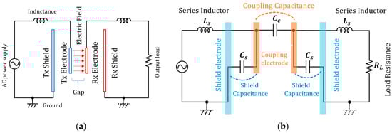
Figure 1.
Configuration and equivalent circuit model of a four-plate S-CPT system: (a) four-plate S-CPT system; (b) equivalent circuit of a four-plate S-CPT system.
The power transmission side consists of a power transmission electrode (Tx-Electrode) and an outer shield electrode (Tx-Shield), while the power reception side consists of a power reception electrode (Rx-Electrode) and a shield electrode (Rx-Shield), forming a pair with a total of four conductors. The shield electrodes are connected to ground (or a low-impedance point), suppressing electric field leakage and stabilizing the return path for the current. The transmitting and receiving electrodes face each other through an air layer and transmit power through electric field coupling. In the equivalent circuit shown in Figure 1b, the coupling between the transmitting and receiving electrodes is modeled as coupling capacitance CC, and the capacitance between the shield electrode and ground is modeled as shield capacitance CS. At the operating frequency, resonance is achieved through the series inductor Ls, supplying power to the load RL.
The shield electrode performs the following functions simultaneously.
(i) EMI suppression: concentrates the main electric field between the Tx–Rx electrodes and reduces leakage electric fields to pedestrians and vehicle bodies. (ii) Stabilization: ensures a large effective ground capacitance CS to reduce the impedance of the current return path, thereby improving the Q-factor of the coupling path and operational stability. (iii) Environmental resistance: absorbs and mitigates changes in dielectric constant caused by moisture ingress or variations in pavement moisture content on the shield side, thereby suppressing fluctuations in coupling capacitance CC.
As a result, the four-plate configuration is an effective method that simultaneously achieves improved safety through reduced leakage electric fields and high stability against environmental changes and positional shifts.
3. Electrode Material Property Evaluation
In this section, we compared the coupling capacitance of electrode materials in an S-CPT (shielded capacitive power transfer) system and evaluated their suitability. First, we compared the performance of multiple conductive materials in terms of coupling capacitance and transmission efficiency. Next, we focused on ductile cast iron, which is widely used in existing infrastructure components, and investigated the effects of surface properties such as coating, corrosion protection, and surface roughness on electric field coupling characteristics and shielding performance.
Based on these results, we will evaluate the applicability of ductile cast iron as an electrode for the S-CPT system and provide guidelines for material selection aimed at developing a low-cost, high-durability system utilizing road infrastructure.
3.1. S-CPT Electrode Material Characteristics #1
Five types of electrode materials were selected for use in the S-CPT system: copper, aluminum, ductile cast iron, structural steel, and carbon steel. The conductivity, relative permeability, and specific resistance of each material are shown in Table 1, and their appearances are shown in Figure 2.

Table 1.
Typical electrical characteristics of evaluated materials.
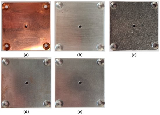
Figure 2.
Electrode materials evaluated: (a) copper; (b) aluminum; (c) ductile cast iron; (d) structural steel; (e) carbon steel.
The electrical properties of the electrode materials evaluated were set based on physical property data. The conductivity, resistivity, and magnetic permeability of copper and aluminum were taken from [41,42], while the characteristic values for ductile cast iron were taken from [43,44]. The values for structural steel and carbon steel were set by referencing standard databases for steel materials and research on magnetic property evaluation [45,46].
Copper was chosen due to its high conductivity and being non-magnetic. It is widely used as a standard material for wireless power transmission, making it suitable as a reference material for loss evaluation. Aluminum was chosen because it is lightweight and non-magnetic, and suitable for large-area electrodes and low-cost designs. From the perspective of durability, it is assumed that it will be buried underground in areas subject to heavy loads, such as roadways. Ductile cast iron was chosen as it is widely used in existing infrastructure such as manhole covers, and it has high durability even when installed on roadways where it is run over by cars. Structural steel was chosen as it is a low-carbon steel widely used in the construction and infrastructure fields. It was selected to evaluating the influence of magnetic properties due to its high magnetic permeability. Carbon steel is a medium-carbon steel used in mechanical components. It was adopted to confirm suitability for structural applications due to its intermediate electrical conductivity and magnetic permeability.
The electrical properties of the electrode materials evaluated were set based on physical property data. The conductivity, resistivity, and magnetic permeability of copper and aluminum were referenced taken from [41,42], while the characteristic values for ductile cast iron were taken from [43,44]. The values for structural steel and carbon steel were set by referencing standard databases for steel materials and research on magnetic property evaluation [45,46].
The experimental methods and evaluation techniques used in this study are based on previous research by Erel et al. [26]. In that study, in addition to the design of a four-plate coupler, S-parameter measurements using a vector network analyzer (VNA) were combined with a π-type equivalent circuit model to calculate impedance characteristics and coupling capacitance. Based on this method, we converted the measured S-parameters into an admittance matrix (Y-parameters) and extracted the main capacitive component.
The experimental setup is shown in Figure 3a. Figure 3b shows the π-type equivalent circuit model used to represent the capacitive coupling structure. This model consists of a central coupling capacitance Cc between the electrodes, and two shunt capacitances Cs to ground that account for the shielding effect of the surrounding conductors. Such π-type equivalent networks are widely employed in microwave circuit analysis to describe the input admittance of two-port systems and to provide a direct mapping between measured Y-parameters and lumped-element circuit components [47].
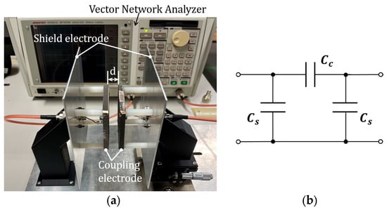
Figure 3.
Experimental setup and equivalent circuit: (a) Experimental setup; (b) equivalent circuit.
The scattering parameters (S-parameters) were first obtained using a vector network analyzer (VNA). As shown in (1), the S-parameters relate the incident waves (a1, a2) and reflected waves (b1, b2) at each port through the scattering matrix [47].
To evaluate the admittance characteristics of the device under test, the obtained S-parameters were converted to Y-parameters according to the standard transformation formula given by Equation (2) [47,48].
Here, E is the unit matrix, and Z0 is the characteristic impedance. The reference impedance was set to Z0 = 50 Ω. This value is widely recognized as the de facto global standard in high-frequency circuit measurements. The 50 Ω system is universally adopted in vector network analyzers, coaxial cables, calibration kits, and RF components, which ensures impedance matching between instruments and minimizes unwanted reflections. Therefore, adopting 50 Ω as the characteristic impedance provides both technical validity and practical relevance for the present analysis.
For a two-port network, the explicit form of the Y-parameter matrix can be expressed as (3). This expanded representation provides direct access to each admittance parameter in terms of the measured S-parameters [48].
Finally, for the equivalent circuit representation used in this study, the Y-parameter matrix can be mapped onto lumped-element admittances as shown in (4) [47].
Here, Y1, Y2, and Y3 after conversion are the admittances of the π-type equivalent circuit in Figure 3b. In the four-plate S-CPT, Y2 corresponds to the coupling capacitance CC, and Y1 and Y3 correspond to the shield capacitance CS. Therefore, each capacitance component is calculated by the following equations.
Here, f is the measurement frequency.
In this study, f = 13.56 MHz was adopted. This frequency is allocated for industrial, scientific, and medical (ISM) applications, and since regulatory frameworks and testing standards are well-established in various countries, evaluation and implementation are relatively straightforward. Additionally, this frequency is widely used in proximity-type RFID/NFC devices, including ISO/IEC 14443 [49], and a rich measurement environment is readily available.
The coupling electrode distance d was set to 2–13 mm, and changes in the coupling capacitance CC were evaluated. Theoretically, the coupling capacitance is approximately inversely proportional to the electrode distance, so scanning this range allows for a broad understanding of the sensitivity ∂C/∂d. Furthermore, preliminary VNA measurements confirmed that the sensitivity tends to stabilize within this range. This is because (i) at extremely small gaps, parasitic components caused by fixtures or wiring dominate, making it difficult to achieve reproducibility, while (ii) at extremely large gaps, the coupling capacitance becomes very small, leading to a decrease in S/N. However, within the 2–13 mm range, the parasitic effects and the measurement system response are balanced, resulting in stable behavior.
The electrode dimensions are set as follows. The coupling electrode is 70 mm × 70 mm with a thickness of 6 mm, and the visible holes are for mechanical fixation. The shield electrode is 150 mm × 150 mm with a thickness of 2 mm. The distance between the coupling electrode and the shield electrode is 40 mm. The 70 mm × 70 mm coupling electrode is easy to handle for measurement and is a size that ensures sufficient coupling capacity and S/N for VNA measurement. The 150 mm × 150 mm shield electrode is set to be sufficiently larger than the coupling electrode, and by containing the fringe electric field from the periphery within the shield, leakage reduction and disturbance suppression (guard effect) are improved. The thickness of the coupling electrode (6 mm) was selected to ensure stable manufacturing during casting, while the thickness of the shielding electrode (2 mm) was determined to balance conductivity and rigidity.
Furthermore, in order to extract the pure characteristics of the coupling capacitance, no resonant inductors were used, and only the capacitance components between the electrodes were considered.
Figure 4 shows the frequency response of S11 versus the electrode gap distance (varying from 2 mm to 13 mm) for the primary materials.
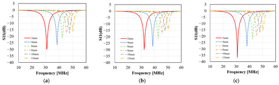
Figure 4.
Electrode gap and S11 characteristics for major materials: (a) copper; (b) aluminum; (c) cast iron.
Figure 4a Copper: A distinct resonance dip appears near 30 MHz at gaps of 2 mm and 4 mm. As the electrode gap increases, the resonance frequency monotonically shifts toward higher frequencies. Figure 4b Aluminum: Similarly, to copper, a deep S11 dip is observed near 30 MHz at a 2 mm gap. As the gap increases, resonance shifts to higher frequencies, but the resonance point occurs at slightly higher frequencies than copper. Figure 4c Ductile cast iron exhibits greater metallic loss, yet a clear resonance is confirmed around 30 MHz at a 2 mm gap. As the gap increases, resonance shifts to higher frequencies, and the dip depth becomes slightly shallower. A consistent trend (resonance frequency shift with increasing electrode gap) is observed across all materials. This is considered to reflect the intrinsic characteristics of the electrode gap. Furthermore, while the resonance depth (minimum S11 value) varies by material, a systematic change with electrode gap and a tendency to converge to a constant value can be confirmed.
Figure 5 shows the frequency response of the transmission coefficient (S21) as a function of the electrode gap for three materials, Figure 5a copper, Figure 5b aluminum, and Figure 5c FCD700 cast iron), corresponding to S11 in Figure 4. In all cases, a distinct resonance peak is observed, and the resonance frequency systematically shifts toward higher frequencies as the electrode gap increases.
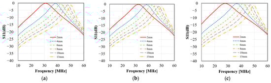
Figure 5.
Electrode gap and S21 characteristics for major materials: (a) Copper; (b) aluminum; (c) cast iron.
Furthermore, the resonance peaks observed in S21 show a good correlation with the corresponding minima in S11, confirming the strong relationship between input matching and transmission performance. The curves are smooth and continuous across the entire measured frequency range, with no discontinuities or irregular fluctuations, supporting the reliability of the experimental data. Considering the clear resonance identification, consistent shift with electrode gap, and correlation with S11, the presented results can be judged to possess a certain level of reliability. Further data acquisition is necessary for statistical analysis.
Based on the above, the measurement data is considered to have a degree of reliability; however, the impact of variation due to individual material differences must be addressed in future research.
Figure 6 shows the inter-electrode distance characteristics of the coupling capacitance CC for each electrode material.
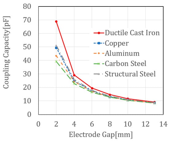
Figure 6.
Coupling capacitance for each electrode material’s inter-electrode distance characteristics.
For all materials, CC decreases with increasing inter-electrode distance, confirming that the coupling capacitance is strongly dependent on distance. In particular, ductile cast iron showed a higher CC than other materials, reaching approximately 70 pF at a gap of 2 mm. Additionally, despite their high magnetic permeability, carbon steel and structural steel exhibit CC values similar to those of copper and aluminum, indicating that the influence of magnetic materials is limited in the four-plate configuration of the S-CPT adopted in this study.
The high capacitance of ductile cast iron under close proximity conditions is attributed to the influence of electric field concentration caused by surface properties and conductivity. While sufficient coupling performance is expected for the S-CPT system electrodes, further investigation is necessary regarding losses, heat generation, and the effects of surface treatment due to low conductivity.
3.2. S-CPT Electrode Material Characteristics #2
In this section, we compare and evaluate the effects of differences in surface properties of ductile cast iron electrodes on electric field coupling characteristics. The three surface conditions examined are as follows. (i) As-cast surface, which is the unprocessed, uncoated cast surface as received, (ii) surface machining, where the cast surface is mechanically machined (milled) to smooth the surface and enhance surface homogeneity, and (iii) surface coating, where an insulating coating is formed by electrocoating. Electrocoating was performed using cationic electrodeposition (CED), with an epoxy resin-based coating material. CED exhibits excellent adhesion to cast iron substrates, corrosion resistance, and the ability to form a uniform coating thickness [50].
As an evaluation method, CC was measured for each surface state using the S-CPT configuration, and the effects of surface roughness and the presence or absence of film formation were compared.
Figure 7 shows the cast iron electrodes evaluated for three surface conditions.
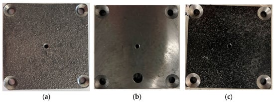
Figure 7.
TP photos for evaluating differences in ductile cast iron surface properties: (a) As-cast surface; (b) surface machining; (c) surface coating.
Figure 7a depicts the unprocessed, uncoated surface immediately after casting. The surface roughness of the casting surface is approximately 20 Ra (arithmetic mean roughness). Figure 7b shows the machined surface, where the casting surface was smoothed by machining (cutting) to improve surface uniformity. This time, the surface roughness Ra was adjusted to 1.6–6.3 by milling. Figure 7c shows the surface coating, where an insulating film was formed by electrodeposition coating. During the manufacturing process, the coating thickness was controlled to approximately 50 μm. All samples were prepared using electrodes of identical shape, with only the surface condition altered.
Figure 8 shows the VNA measurement results of the electrode gap d and CC in the range of 2–13 mm.
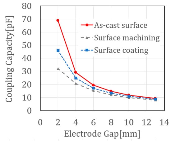
Figure 8.
Relationship between electrode gap and capacitance according to ductile iron surface properties.
As expected, the coupling capacitance CC decreases with an increase in the electrode-to-electrode gap d. In particular, in the small gap region (d = 2–4 mm), the as-cast surface exhibits the maximum CC (approximately 70 pF at d = 2 mm), the machined surface shows the minimum (approximately 30 pF), and the painted surface lies intermediate between them (approximately 45 pF). This is attributed to the fact that the micro-protrusions on the cast surface contribute to the effective area, while machining reduces the effective area. The painted surface exhibits a slight increase in series thickness due to a thin dielectric film (εr ≈ 3–4), which lowers CC, and a local increase in the dielectric constant near the interface, which raises CC, with these effects canceling each other out, resulting in an intermediate value.
In the large gap region (d ≥ 6 mm), evaluation of the relative change rate shows that while fluctuations exceeding 30% remain in the low gap region (2–6 mm), they decrease to around 20% for gaps of 8 mm or greater, confirming a convergence trend among the three curves. Since the coupling capacity is governed by the gap, the influence of surface finish can be disregarded. Therefore, it can be judged that this reflects physically plausible behavior. However, strict convergence criteria (e.g., ≤5%) are not yet met, and further repeated measurements or an increased sample size are necessary for statistical evaluation. This indicates that, for designs with gaps of 6 mm or larger, prioritizing corrosion resistance and durability by using painted surfaces results in only a slight reduction in capacitance. Conversely, for gaps of 4 mm or smaller, surface condition significantly affects CC. This means that using cast surfaces or surfaces with appropriate texturing may yield high coupling characteristics.
The electrode gap d depends on the electrode size, and the required clearance increases with larger sizes. Specifically, factors such as vehicle regulations, electrode plate deflection and out-of-plane vibration, road surface irregularities and construction variations, and thermal expansion require safety margins to avoid contact. Additionally, the ratio of the electrode’s planar dimension S to the gap d (S/d) is also important. The selection of electrode size should ideally optimize CC characteristics, vehicle regulations, load-bearing capacity, planarity, and electromagnetic requirements simultaneously.
4. S-CPT Power Transmission Experiment Using Cast Iron Cover Electrodes and Load Resistance Evaluation
Previous evaluations of electrode materials have demonstrated that ductile cast iron can function as an effective electrode material for S-CPT. Ductile cast iron possesses higher mechanical strength and ductility compared to copper and aluminum, and its one-piece casting process enables flexible shape design, such as thickness optimization and curved surface formation. In wireless power supply systems for EVs installed on road surfaces, the cast iron electrodes are exposed flush with the road surface, minimizing the gap between the electrodes on the vehicle and the electrodes on the road surface, which directly improves coupling efficiency. Installation can be performed using the same procedures as for existing cast iron covers, making replacement and inspection and maintenance easy. Additionally, drainage openings and anti-slip patterns cast into the structure ensure long-term water drainage and road surface friction. In terms of mechanical properties, the tensile strength exceeds 700 N/mm2, the yield stress at 0.2% is 420 N/mm2, and the elongation exceeds 3% [51], ensuring structural reliability capable of withstanding direct wheel loads. In summary, ductile cast iron is a promising candidate material for achieving both robust road infrastructure and high-efficiency WPT.
4.1. Power Transmission Experiment Using S-CPT System with Cast Iron Cover as an Electrode
As shown in Figure 9, we conducted power transmission experiments using cast iron cover electrodes with a four-plate S-CPT (shielded capacitive power transmission) system.
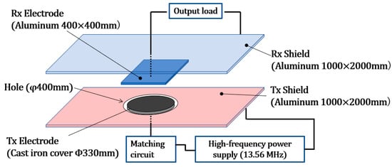
Figure 9.
Four-plate S-CPT power transmission experiment configuration using cast iron covers as electrodes.
The power transmission electrode (Tx electrode) is made of cast iron (outer diameter: 330 mm), and the Tx shield (aluminum, 1000 × 2000 mm) is designed so that the Tx electrode can be placed in a Φ400 hole and positioned on the same plane. This design takes into consideration practicality, assuming that the cast iron electrodes will be exposed to the road surface and that maintenance boxes will be installed inside the cast iron covers. The power-receiving electrode (Rx electrode) is made of aluminum (400 × 400 mm), and the Rx shield (aluminum, 1000 × 2000 mm) is constructed on its back surface.
A 13.56 MHz high-frequency power supply is used, and the power is applied to the Tx electrode via a matching device. On the receiving side, the power from the Rx electrode is recovered via a load resistor, and the transmission efficiency is evaluated. In this experiment, the electrode gap was fixed at 30 mm, and the impedance matching was adjusted. The effect of the relative offset of the electrode positions on the transmission characteristics was also evaluated.
This system was designed and manufactured based on a mock-up that was approximately half the size of an actual small vehicle. The power transmission electrode (cast iron cover, Ø330 mm) is a realistic size based on actual road sewer cover standards [52,53]. It is expected to provide sufficient coupling capacity while maintaining structural strength.
The shield electrodes (1000 × 2000 mm) were designed with sufficient width to suppress external leakage of the electric field. The size was set to the minimum practical size that can achieve shielding effects in the experimental environment. The electrode gap of 30 mm was set to accommodate actual road surface installation conditions, aiming to balance structural safety and high coupling capacity.
4.2. Main Dimensions and Structural Analysis of Cast Iron Cover Electrodes Used in Power Transmission Experiments
Figure 10a shows the structure of the cast iron cover used in the output test.
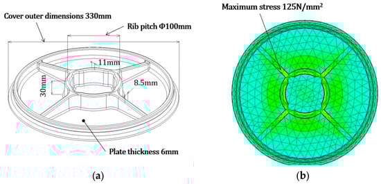
Figure 10.
Stress distribution analysis of Φ330 mm cast iron cover using electrode structure and the finite element method: (a) Main dimensions of Φ330 mm cast iron cover electrode; (b) stress distribution analysis using the finite element method.
The cover’s outer diameter is 330 mm. The rib structure on the underside of the lid combines Φ100 mm circular ribs with radial ribs. The central rib height is 30 mm. Rib thickness is 11 mm at the base and 8.5 mm near the connection to the outer edge. The cover plate thickness is uniformly 6 mm. Cast iron covers are widely used in roads and public infrastructure due to their high load resistance, durability, and resistance to environmental degradation. They are usually made from spheroidal graphite cast iron by pouring molten iron into sand or metal molds and allowing it to solidify. The fine microstructure, where spherical graphite is distributed within a ferrite–pearlite structure, exhibits superior tensile strength, impact resistance, and fatigue durability compared to gray cast iron. With tensile strength exceeding 700 N/mm2, a yield stress of over 420 N/mm2 at 0.2%, and an elongation rate exceeding 3%, it can withstand design loads for heavy vehicles in accordance with road design standards through structural optimization and lightweight design.
The material properties of the ductile cast iron used in this study were defined as follows: Young’s modulus E = 166.71 × 10³ N/mm2, Poisson’s ratio ν = 0.28, and tensile strength σb = 700 N/mm2. The boundary and loading conditions of the finite element model were specified as follows: the entire outer edge, corresponding to the supporting surface of the cover, was fully constrained. According to the Japan Sewerage Works Association standard, a concentrated load equivalent to the impact of a 25-ton vehicle was applied. This load was distributed over a circular area with a diameter of ϕ170 mm, resulting in a total applied load of 35 kN. For the mesh configuration, second-order tetrahedral elements were employed. The convergence criterion was defined such that convergence was achieved when the difference between successive calculation steps fell below 10%.
From a structural point of view, cast iron covers are machined to fit securely into frames embedded in the pavement. The upper surface may be provided with a non-slip pattern for safety. The underside of the cover is structurally optimized with reinforcing ribs to increase rigidity and distribute the load evenly. Figure 10b shows the results of a structural analysis of the stress generated by the design load when installed on a road. Considering the fatigue of ductile cast iron, the allowable stress is 235 N/mm2 [54], and the analysis results confirm that the maximum stress generated is 125 N/mm2, which is sufficient strength. The structural analysis was performed using the finite element method (FEM) with the commercial software package NX (Siemens Digital Industries Software, Germany, latest version at the time of analysis).
4.3. Four-Plate S-CPT System Configuration and Impedance Matching
Figure 11 shows the equivalent circuit of the S-CPT system using four electrodes employed in the electrode transmission experiment, employing a π-type matching circuit for impedance matching.
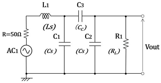
Figure 11.
Design and impedance matching of a four-plate S-CPT System: LTspice-based equivalent circuit analysis (The matching network adopts a π-type topology).
The shunt branch is handled by the coupling capacitors C1 and C2, while the series branch consists of the inductor L1 and the capacitor C3. This provides the required series reactance, achieving conjugate matching between the signal source (50 Ω) and the load. This research operates at the internationally standardized 13.56 MHz ISM band.
In this model, an actual cast iron cover was used as the transmitting electrode, and the capacitances C1, C2, and C3 were measured experimentally with an electrode-to-electrode distance of 30 mm. The measured values were C3 = 60 pF, C1 = 30 pF, and C2 = 70 pF.
π-type matching was adopted because (i) it ensures a wide matching range for capacitive loads, (ii) it is robust against electrode gap variations, (iii) it is advantageous for suppressing circulating currents and improving unwanted radiation (EMI) characteristics, and (iv) it facilitates implementation in the high-frequency (HF) band.
The design procedure involved first extracting equivalent circuit values from measured S-parameters and then calculating the values of L1 and CC using standard π-network design equations. Subsequently, AC analysis was performed using LTspice (Analog Devices, Inc., Wilmington, MA, USA, Version 24.0.1, latest version at the time of analysis) to confirm that S11 was minimized.
To achieve impedance matching, the load resistance RL and primary inductance L1 were varied in the simulation, and the optimal values RL = 200 Ω and L1 = 2 μH were determined.
Figure 12 shows the simulation results of S11 for the entire S-CPT system. It shows the designed resonance characteristics and impedance matching characteristics. At 13.56 MHz, the value was approximately −10 dB, which was judged to be sufficient.
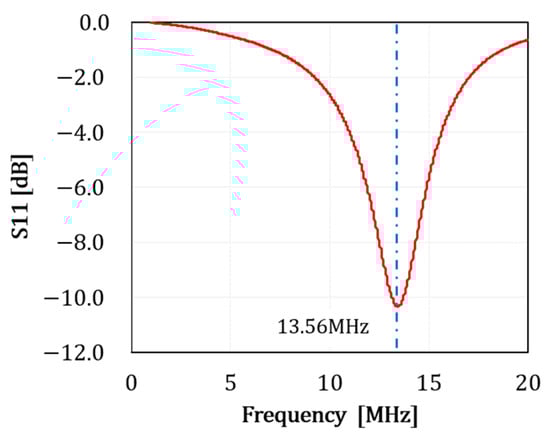
Figure 12.
Simulation result of reflection coefficient (S11) of designed S-CPT system.
4.4. EMI Characteristics
To confirm the electromagnetic interference (EMI) characteristics of the proposed S-CPT system, we reproduced the experimental model and performed a numerical analysis. The analysis model is shown in Figure 13a.
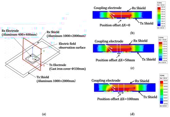
Figure 13.
EMI analysis results: (a) EMI characteristics confirmation analysis model; (b) electric field distribution (zero electrode displacement); (c) Electric field distribution (electrode position deviation 50 mm); (d) Electric field distribution (electrode position deviation 100 mm).
Analysis was carried out using ANSYS Maxwell (Ansys, Inc., USA, Version 2023 R2, Student Version), a finite element method-based electromagnetic field analysis software developed and provided by ANSYS, Inc. (Headquarters: Canonsburg, PA, USA).
We set the relative positions of the power transmission and reception electrodes to 50 mm and 100 mm and compared the behavior of the electric field and the effects of the shield electrodes. The analysis results are shown in Figure 13b. The results confirmed that even when the electrodes were misaligned, the shield electrodes suppressed unnecessary radiation and effectively reduced electric field leakage.
4.5. Power Transmission Test Results
The experimental setup is shown in Figure 14.
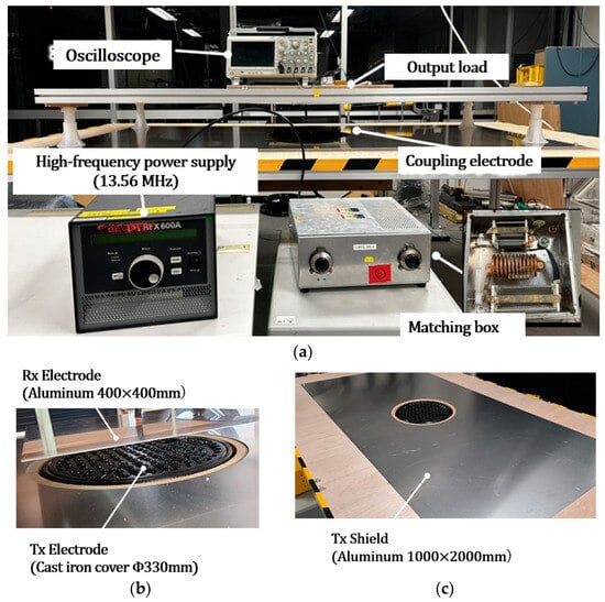
Figure 14.
Power transmission experiment for S-CPT system mockup using cast iron covers as electrodes: (a) Measurement setup; (b) coupling electrode configuration using aluminum plates and cast-iron covers; (c) cast iron cover electrodes installed inside the shield electrodes.
Figure 14a shows the measurement setup, and Figure 14b shows the configuration of the coupling electrodes using an aluminum plate and a cast iron cover. Figure 14c shows the arrangement of the cast iron cover electrodes installed in the shield electrodes. The experiment was conducted using a high-frequency power supply set at a frequency of 13.56 MHz. In this experiment, we verified whether wireless power transmission was possible within a range of 100 W to 300 W of input power while maintaining a constant distance between the electrodes. Impedance matching was achieved using a resonant circuit implemented within a dedicated matching box.
For the output measurement, the voltage was measured by connecting both ends of the load resistance to an oscilloscope as shown in Figure 14a. The transmission efficiency η [%] was compared for an input power ranging from 100 W to 300 W, with the lateral displacement (position deviation) set to 0 mm, 100 mm, and 200 mm. Here, efficiency is defined as η = Pout/Pin × 100% (effective power supplied to the load/input power).
Figure 15 shows the transmission efficiency as a function of input power, comparing the effects of lateral misalignment (0 mm, 100 mm, and 200 mm).
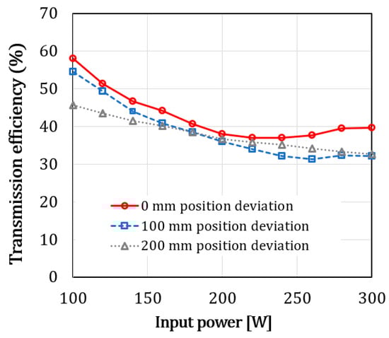
Figure 15.
Transmission efficiency versus input power under lateral misalignment.
The vertical axis represents the transmission efficiency (%) and the horizontal axis represents the input power (W). When there is no misalignment, the efficiency is highest, with a result of approximately 58% at 100 W input. As the input power increases, the efficiency gradually decreases, reaching approximately 37% around 200 W, and then stabilizes at around 40%. For a 100 mm position offset, overall efficiency is lower compared to when there is no position offset, but at 100 W input, it is approximately 53%, and at 200 W, it is approximately 36%, indicating a relatively small decrease. Similarly, with a 200 mm position offset, efficiency is approximately 45% at 100 W input and remains around 30–32% at 200 W and above. It is confirmed that the effect of position offset is relatively small.
Under all conditions, the efficiency decreases as the input power increases. This is believed to be due to the significant effects of parasitic losses and impedance mismatch at high input power levels. However, it was also confirmed that efficiency converges to a nearly constant value at 200 W and above.
To ensure practical efficiency, lateral positional deviation should be kept to approximately 100 mm, though this may vary depending on electrode size. Additionally, to compensate for efficiency degradation at high power levels, additional design measures such as impedance matching circuits or auxiliary electrodes are considered effective.
5. Conclusions
In this study, we demonstrated the effectiveness of a shielded capacitive power transmission (S-CPT) system using cast iron covers as transmission electrodes that meet the durability requirements for installation on actual roads.
In a mock-up experiment at half the actual scale, the system achieved a power transmission efficiency of 58% at an input power of 100 W, maintained approximately 40% efficiency even at an output exceeding 200 W, and retained 45% efficiency even with a lateral offset of 200 mm between the electrodes.
Material evaluation, prototype experiments, and electromagnetic simulations confirmed that cast iron provides coupling capacitance equivalent to copper and aluminum while maintaining the mechanical strength required for road infrastructure.
The shielded electrodes effectively suppressed unwanted electromagnetic fields, demonstrating the potential to meet electromagnetic compatibility requirements.
The proposed system is shown in Figure 16. Reusing cast iron covers as transmitting electrodes in urban areas and exposing the electrodes to the road surface makes it easy to secure the necessary spacing between electrodes. This eliminates the need to bury new large coils and simplifies the vehicle-side system, contributing to smaller batteries and lighter EVs.
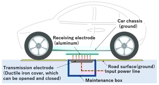
Figure 16.
System overview of the proposed S-CPT/DWPT segment.
Going forward, we will address several challenges to scale up the proposed system for high-power electric vehicle charging. First, the electrode structure must be optimized to sustain high efficiency even under large electrode gaps and positional misalignments. Second, low-loss and high-efficiency impedance matching circuits need to be developed to improve overall system performance. Third, thermal management strategies must be established to ensure stable operation under high-power conditions. In addition, the influence of the selected electrode size on coupling capacitance, electric field distribution, and misalignment tolerance should be systematically evaluated through simulation and theoretical analysis. These studies will provide stronger design justification and enhance the reliability of the proposed S-CPT system toward practical implementation.
Additionally, we will conduct long-term durability and safety tests under real-road conditions to verify the reliability of the cast iron electrodes.
Author Contributions
Conceptualization, N.K. (Nobuhiro Kai); Methodology, N.K. (Naoki Kojo); Validation, N.K. (Naoki Kojo) and Y.I.; Formal analysis, H.C.; Investigation, N.K. (Nobuhiro Kai) and T.Y.; Resources, T.H. and K.U.; Data curation, H.C.; Writing—original draft preparation, E.T.; Writing—review and editing, E.T.; Supervision, N.K. (Nobuhiro Kai), R.H. and H.K.; Project administration, E.T., T.H. and K.U. All authors have read and agreed to the published version of the manuscript.
Funding
This research received no external funding.
Data Availability Statement
The data presented in this study are available on request from the corresponding author. The data are not publicly available due to industrial confidentiality and cooperative research agreements with partner organizations.
Conflicts of Interest
Authors Eiichi Tateishi, Yuta Ide, Nobuhiro Kai, Toru Hashimoto, Kota Uchio was employed by the company Hinode Holdings Ltd. Authors Tatsuya Yamaguchi was employed by the company Hinode Ltd. The remaining authors declare that the research was conducted in the absence of any commercial or financial relationships that could be construed as a potential conflict of interest.
References
- Timilsina, R.R.; Zhang, J.; Rahut, D.B.; Patradool, K.; Sonobe, T. Global drive toward net-zero emissions and sustainability via electric vehicles: An integrative critical review. Energy Ecol. Environ. 2025, 10, 125–144. [Google Scholar] [CrossRef]
- IEA. Global EV Outlook 2024; International Energy Agency: Paris, France, 2024; Available online: https://www.iea.org/reports/global-ev-outlook-2024 (accessed on 29 June 2025).
- International Energy Agency (IEA). Net Zero by 2050—Analysis, 2021. Available online: https://www.iea.org/reports/net-zero-by-2050?utm_source=chatgpt.com (accessed on 29 June 2025).
- Adam, K. Most New Cars in Norway are EVs. The Washington Post, 30 May 2025. Available online: https://www.washingtonpost.com/climate-solutions/2025/05/30/norway-ev-adoption-electric-cars/?utm_source=chatgpt.com (accessed on 29 June 2025).
- Zhao, X.; Hu, H.; Yuan, H.; Chu, X. How does adoption of electric vehicles reduce carbon emissions? Evidence from China. Heliyon 2023, 9, e20296. [Google Scholar] [CrossRef] [PubMed]
- S&P Global Mobility. Affordability Tops Charging and Range Concerns in Slowing EV Demand. November 2023. Available online: https://www.spglobal.com/mobility/en/research-analysis/affordability-tops-charging-and-range-concerns-in-slowing-ev-d.html (accessed on 29 June 2025).
- NREL. Soft Cost Analysis of EV Charging Infrastructure Informs Transition to an Electric Fleet, National Renewable Energy Laboratory. 2024. Available online: https://www.nrel.gov/news/detail/program/2024/soft-cost-analysis-of-ev-charging-infrastructure-informs-transition-to-an-electric-fleet (accessed on 29 June 2025).
- Bi, Z.; Kan, T.; Mi, C.C.; Zhang, Y.; Zhao, Z.; Keoleian, G.A. A review of wireless power transfer for electric vehicles: Prospects to enhance sustainable mobility. Appl. Energy 2016, 179, 413–425. [Google Scholar] [CrossRef]
- Yuvaraja, S.; Narayanamoorthi, R.; Mohamed Ali, J.S.; Almakhles, D. A Comprehensive Review of the On-Road Wireless Charging System for E-Mobility Applications. Front. Energy Res. 2022, 10, 926270. [Google Scholar] [CrossRef]
- Sun, H.; Ma, X.; Hu, R.Q.; Christensen, R. Precise Coil Alignment for Dynamic Wireless Charging of Electric Vehicles with RFID Sensing. arXiv 2021, arXiv:2107.11428. Available online: http://arxiv.org/abs/2312.12565 (accessed on 29 June 2025). [CrossRef]
- Ghassemi, A.; Soares, L.; Wang, H.; Xi, Z. A Novel Mathematical Model for Infrastructure Planning of Dynamic Wireless Power Transfer Systems for Electric Vehicles. arXiv 2021, arXiv:2107.11428. Available online: http://arxiv.org/abs/2107.11428 (accessed on 29 June 2025). [CrossRef]
- Wang, C.; Nguyen, H.D. Steady-state Voltage Profile and Long-term Voltage Stability of Electrified Road with Wireless Dynamic Charging. arXiv 2019, arXiv:1906.00903. Available online: http://arxiv.org/abs/1906.00903 (accessed on 29 June 2025).
- Ma, X.; Yuan Zhou, Y.; Zhang, H.; Wang, Q.; Sun, H.; Wang, H.; Hu, R.Q. Exploring Communication Technologies, Standards, and Challenges in Electrified Vehicle Charging. arXiv 2024, arXiv:2403.16830. Available online: http://arxiv.org/abs/2403.16830 (accessed on 29 June 2025). [CrossRef]
- Van Mulders, J.; Delabie, D.; Lecluyse, C.; Buyle, C.; Callebaut, G.; Van der Perre, L.; De Strycker, L. Wireless Power Transfer: Systems, Circuits, Standards, and Use Cases. Sensors 2022, 22, 5573. [Google Scholar] [CrossRef]
- SAE International. SAE International Finalizes Light Duty Wireless Charging ‘Gamechanger’ Standard to Enable Mass Commercialization. Available online: https://www.sae.org/news/press-room/2024/08/sae-j2954?utm_source=chatgpt.com (accessed on 29 June 2025).
- Mohamed, A.; Shaier, S. Evaluation of power transfer efficiency with ferrite sheets in WPT system. In 2017 IEEE Wireless Power Transfer Conference, Taipei, Taiwan, 10–12 May 2017; IEEE: Piscataway, NJ, USA, 2017; Available online: https://www.researchgate.net/publication/317824866 (accessed on 29 June 2025).
- IEA. Global Critical Minerals Outlook 2025. Available online: https://iea.blob.core.windows.net/assets/a33abe2e-f799-4787-b09b-2484a6f5a8e4/GlobalCriticalMineralsOutlook2025.pdf (accessed on 29 June 2025).
- Rhee, J.; Woo, S.; Lee, C.; Ahn, S. Selection of Ferrite Depending on Permeability and Weight to Enhance Power Transfer Efficiency in Low-Power Wireless Power Transfer Systems. Energies 2024, 17, 3816. [Google Scholar] [CrossRef]
- Wang, D.; Zhang, J.; Cui, S.; Bie, Z.; Song, K.; Zhu, C.; Matveevich, M.I. Modern Advances in Magnetic Materials of Wireless Power Transfer Systems: A Review and New Perspectives. Nanomaterials 2022, 12, 3662. [Google Scholar] [CrossRef]
- Digital Commons USU. All Graduate Theses, and T. Gardner. Wireless Power Transfer Roadway Integration. 2017. Available online: https://digitalcommons.usu.edu/etd/6866 (accessed on 29 June 2025).
- Honjo, Y.; Caremel, C.; Kawahara, Y.; Sasatani, T. Suppressing Leakage Magnetic Field in Wireless Power Transfer Using Halbach Array-Based Resonators. IEEE Antennas Wirel. Protag. Lett. 2024, 23, 94–98. [Google Scholar] [CrossRef]
- Niu, S.; Jia, Q.; Hu, Y.; Yang, C.; Jian, L. Safety Management Technologies for Wireless Electric Vehicle Charging Systems: A Review. Electronics 2025, 14, 2380. [Google Scholar] [CrossRef]
- Poguntke, T.; Schumann, P.; Ochs, K. Radar-based living object protection for inductive charging of electric vehicles using two-dimensional signal processing. Wirel. Power Transf. 2017, 4, 88–97. [Google Scholar] [CrossRef]
- Qi, Y.; Espinoza-Andaluz, M.; Thern, M.; Andersson, M. Polymer electrolyte fuel cell system level modelling and simulation of transient behavior. eTransportation 2019, 2, 100030. [Google Scholar] [CrossRef]
- Wang, Z.; Zhang, Y.; He, X.; Luo, B.; Mai, R. Research and Application of Capacitive Power Transfer System: A Review. Electronics 2022, 11, 1158. [Google Scholar] [CrossRef]
- Erel, M.Z.; Bayindir, K.C.; Aydemir, M.T.; Chaudhary, S.K.; Guerrero, J.M. A Comprehensive Review on Wireless Capacitive Power Transfer Technology: Fundamentals and Applications. IEEE Access 2021, 10, 3116–3143. [Google Scholar] [CrossRef]
- Zhou, W.; Li, M.; Zhang, Q.; Li, Z.; Xie, S.; Fan, Y. Potential and challenges of capacitive power transfer systems for wireless EV charging: A review of key technologies. Green Energy Intell. Transp. 2024, 3, 100174. [Google Scholar] [CrossRef]
- Lecluyse, C.; Minnaert, B.; Kleemann, M. A review of the current state of technology of capacitive wireless power transfer. Energies 2021, 14, 5862. [Google Scholar] [CrossRef]
- Taisei Corporation. Roadway Wireless Power Transfer System for Dynamic Charging, National Road Technology Council Report No.2020-6. 2024. Available online: https://www.mlit.go.jp/road/tech/jigo/r06/pdf/report2020-6.pdf (accessed on 29 June 2025).
- Lee, I.-O.; Kim, J.; Lee, W. A high-efficient low-cost converter for capacitive wireless power transfer systems. Energies 2017, 10, 1437. [Google Scholar] [CrossRef]
- Mikelj, M.; Nagode, M.; Klemenc, J.; Šeruga, D. Influence of Operating Conditions on a Cast-Iron Manhole Cover. Technologies 2022, 10, 127. [Google Scholar] [CrossRef]
- Sugi, S. Manhole covers as part of the road Their role. Constr. Mach. 2018, 70. [Google Scholar]
- Mascot Inc. BS EN 124-2. Available online: https://mascotengineering.com/technical-support/en-124-2/?utm_source=chatgpt.com (accessed on 29 June 2025).
- Japanese Standards Association. Spheroidal Graphite Cast Irons. Available online: https://webdesk.jsa.or.jp/preview/pre_jis_g_05502_000_000_2022_e_ed10_ch.pdf?utm_source=chatgpt.com (accessed on 29 June 2025).
- Hinode, Ltd. Characteristics of Spheroidal Graphite Cast Iron. Available online: https://hinodesuido.co.jp/Technology/fcd.html (accessed on 29 June 2025).
- Owada, N.; Okazaki, S.; Hiraoka, T.; Goto, K. Electrical Resistivity of Various Cast Irons. Im. J. Jpn. Foundry Eng. Soc. 1982, 54, 113–118. [Google Scholar]
- Muharam, A.; Ahmad, S.; Hattori, R. Scaling-factor and design guidelines for shielded-capacitive power transfer. Energies 2020, 13, 4240. [Google Scholar] [CrossRef]
- Muharam, A.; Ahmad, S.; Hattori, R.; Hapid, A. 13.56 MHz scalable shielded-capacitive power transfer for electric vehicle wireless charging. 2020 IEEE PELS Work. In Proceedings of the 2020 IEEE PELS Workshop on Emerging Technologies: Wireless Power Transfer (WoW), Seoul, Republic of Korea, 15–19 November 2020; pp. 298–303. [Google Scholar] [CrossRef]
- Ahmad, S.; Muharam, A.; Hattori, R.; Uezu, A.; Mostafa, T.M. Shielded Capacitive Power Transfer (S-CPT) without Secondary Side Inductors. Energies 2021, 14, 4590. [Google Scholar] [CrossRef]
- Zhang, J.; Yao, S.; Pan, L.; Liu, Y.; Zhu, C. A Review of Capacitive Power Transfer Technology for Electric Vehicle Applications. Electronics 2023, 12, 3534. [Google Scholar] [CrossRef]
- Lide, D.R. CRC Handbook of Chemistry and Physics, 90th ed.; CRC Press: Boca Raton, FL, USA, 2009; pp. 12–114. [Google Scholar]
- Davis, J.R. Metals Handbook Desk Edition; ASM International: Materials Park, OH, USA, 1998; pp. 1–85. [Google Scholar]
- Asanuma, H.; Kondo, Y.; Tashiro, K. Electrical Resistivity of Ductile Cast Iron and Its Dependence on Graphite Morphology. Mater. Trans. 2007, 48, 2463–2468. [Google Scholar]
- Nishiyama, K.; Tsuchida, T.; Nakahara, H. Magnetic and electrical properties of spheroidal graphite cast iron. IEEE Trans. Magn. 1993, 29, 3333–3335. [Google Scholar]
- Jiles, M. Introduction to Magnetism and Magnetic Materials, 3rd ed.; CRC Press: Boca Raton, FL, USA, 2015; pp. 87–88. [Google Scholar]
- Bozorth, R.M. Ferromagnetism; IEEE Press: New York, NY, USA, 1993; pp. 27–31. [Google Scholar]
- Pozar, D.M. Microwave Engineering, 4th ed.; Chapter 4; Wiley: Hoboken, NJ, USA, 2012; pp. 176–180. [Google Scholar]
- Frickey, D.A. Conversions between S, Z, Y, h, ABCD, and T parameters which are valid for complex source and load impedances. IEEE Trans. Microw. Theory Tech. 1994, 42, 205–211. [Google Scholar] [CrossRef]
- Wikipedia. ISO/IEC 14443. Available online: https://en.wikipedia.org/wiki/ISO/IEC_14443?utm_source=chatgpt.com (accessed on 29 June 2025).
- Shimizu Co., Ltd. Electroplating. Available online: https://shimizu-corp.co.jp/electroplation/ (accessed on 29 June 2025).
- Tobinaga, H.; Yamaguchi, E.; Murayama, M. Consideration of plastic deformation capacity of spheroidal graphite cast iron to deck slab for highway bridge. J. Struct. Eng. 2018, 64A, 109–119. [Google Scholar]
- Japan Ground Manhole Industry Association. Specifications and Performance of Ground Manholes for Sewerage Systems; Japan Ground Manhole Industry Association: Tokyo, Japan, 1997. [Google Scholar]
- Sewerage Association Standard JSWAS G-4. Available online: https://jgma.gr.jp/manhole-cover/g4second/ (accessed on 29 June 2025).
- Tateishi, E.; Yi, Y.; Kai, N.; Kumagae, T.; Yamaguchi, T.; Kanaya, H. Development of Cast Iron Manhole Cover with Broadband-Radio-Transmission Characteristics Applying Spiral Structure. IEEE Antennas Wirel. Propag. Lett. 2025, 24, 612–615. [Google Scholar] [CrossRef]
Disclaimer/Publisher’s Note: The statements, opinions and data contained in all publications are solely those of the individual author(s) and contributor(s) and not of MDPI and/or the editor(s). MDPI and/or the editor(s) disclaim responsibility for any injury to people or property resulting from any ideas, methods, instructions or products referred to in the content. |
© 2025 by the authors. Licensee MDPI, Basel, Switzerland. This article is an open access article distributed under the terms and conditions of the Creative Commons Attribution (CC BY) license (https://creativecommons.org/licenses/by/4.0/).