Abstract
This paper presents a broadband omnidirectional rectenna combined with a solar cell for hybrid energy harvesting, addressing the daytime-only limitation of solar cells via complementary RF energy harvesting. To avoid mutual interaction in integration, the solar cell is placed above the antenna to receive light/EM waves from different directions. A broadband discone antenna ensures omnidirectional RF reception from 1.56 to 6.63 GHz, while a single-stub matching circuit and voltage doubler enable rectifier operation from 1.4 to 3.6 GHz, with over 50% power conversion efficiency at 5 dBm. The measurement demonstrates that the hybrid system can yield 20.25 mW from combined RF/solar power. This broadband hybrid energy harvesting system shows potential for powering sensors throughout the day by integrating two complementary energy sources with minimal interaction.
1. Introduction
Ambient wireless energy harvesting (WEH) systems can convert RF energy from various sources, such as mobile telephones, wireless routers, mobile base stations, radio broadcast stations, and so on, to direct current (DC) power [1,2]. This capability offers greater flexibility compared to traditional power plants by enabling electricity generation at diverse locations. For low-power devices like Internet of Things (IoT) sensors, distributed RF energy harvesting offers a viable alternative to battery power. While solar cells are environmentally friendly, they possess a significant limitation because of their inability to operate during nighttime due to the absence of sunlight. Rectennas, as a key component in a WEH system, can operate continuously regardless of daylight conditions, serving as an effective complement to solar cells. Therefore, a hybrid RF-solar energy harvester, which integrates RF and solar harvesting systems, has attracted great attention in recent years [3].
In a hybrid RF-solar energy harvester, the solar cell and antenna may obstruct each other when the two components are integrated. Thus, many methods have been proposed to solve this problem [4,5,6,7,8,9,10]. In [4,5,6,7,8], transparent antennas were positioned above the solar cells, so sunlight could penetrate these antennas to reach the solar cells, thereby resolving the issue of antenna-induced shading. However, the approach had the disadvantage that the light could not completely penetrate the transparent antenna because the transparency of the antenna was lower than 100%. In addition, these antennas adopted conductive materials that had lower electric conductivity compared with normal metals such as copper. Therefore, the radiation efficiency of the antenna decreased. Another way to solve this problem is to use the solar cell as a radiation component of the antenna [9,10]. This approach can effectively resolve the interaction between the antenna and the solar cell.
Another problem with a hybrid RF-solar energy harvester is that the rectifier usually has a limited bandwidth. In WEH, RF sources emit extremely low power density, resulting in minimal harvested RF power. By harvesting energy across more frequency bands, more DC power can be generated. Therefore, the rectenna or rectifier is preferred to operate over a broadband or multi-band [11]. Among RF sources for WEH, new 5G base stations operate in frequency bands such as 1.8 and 3.5 GHz, while WiFi operates in the 2.4 GHz ISM band. Consequently, most rectennas are designed to operate within these frequency bands and exhibit high efficiency at low input power levels. In [12], a broadband rectenna within 1.8 to 2.8 GHz was proposed using a modified wideband resistance compression network. In [13], a dual-band rectenna operating at 2.4 and 3.6 GHz bands using a balanced CRLH transmission line with an open termination was introduced. Similarly, a rectenna utilizing a broadband monopole antenna was proposed to operate at the 2.4 GHz WiFi band and 3.5 GHz 5G band [14]. However, none of these designs can cover the frequency band from 1.8 to 3.6 GHz.
On the other hand, many efforts have been devoted to hybrid RF and solar energy harvesting systems [15,16,17,18,19]. Wan et al. proposed a metal mesh antenna operating at 2.45 GHz, which positioned the solar cell under the metal mesh [15]. Using a thin metal mesh can reduce the shade of the antenna on the solar cell. However, the antenna has a very narrow bandwidth of 2.36 to 2.53 GHz. Bito et al. described an RF and solar energy harvesting system operating in the 2.4 GHz band that adopted 3D printing technology [16]. The solar cell was also set on top of the antenna. This approach minimizes the shade of the solar cell. But the bandwidth of the implemented antenna is still narrow, from 2.28 to 2.55 GHz. In [17], a flexible rectenna-integrated solar cell for harvesting RF signals at 850 and 1850 MHz using a PET substrate was proposed. In [18], a flexible rectenna using a flexible transparent rectenna was designed to work at 3.5–3.578 and 4.79–5.09 GHz. The merit of a flexible energy harvesting system is that it can conform to objects or the human body. In [19], a 5.8 GHz metal mesh optically transparent metasurface was integrated with a solar cell to harvest hybrid energy. The system uses a metal mesh to construct the metasurface and to integrate the solar cell so that it has a miniaturized structure. However, its ambient RF energy harvesting ability is limited. The power conversion efficiency (PCE) of the proposed rectifier is less than 30% at an input power level of 0 dBm. The output voltage of the hybrid energy harvesting system is less than 0.15 mW at an input power level of 0 dBm with a load of 600 Ω.
This paper presents a broadband omnidirectional rectenna combined with a solar cell for hybrid energy harvesting. The problems addressed and the innovations of this paper are summarized as follows:
- A circular metal patch and inclined shorting pins were used to create a broadband omnidirectional antenna that also serves as a supporting structure for the solar cell.
- The antenna and solar cell employ a distinct directional separation mechanism. The solar cell receives light from above, while the antenna captures incoming electromagnetic waves from the azimuthal direction, thereby resolving the mutual obstruction issue between the two components.
- A broadband rectifier circuit was realized through the incorporation of a single-stub matching network and a voltage doubler topology, effectively addressing the conventional limitation of narrow bandwidth in rectifier circuits.
The measured results show that the proposed omnidirectional discone antenna with a solar cell has a gain of −0.3 to 5.6 dBi from 1.6 to 3.6 GHz and the rectifier circuit has a PCE over 50% from 1.4 to 3.6 GHz with a load of 1 kΩ. The rectifier’s maximum efficiency can reach 66% at 3.3 GHz when the input power is 13 dBm. Moreover, the experiment proved that the hybrid energy harvester can produce more DC power than each single component. A demonstration was carried out to prove that the proposed rectenna integrated with a solar cell can drive the temperature and humidity indicators by harvesting RF and solar energy.
This article is organized as follows. Section 2 introduces the design of the proposed broadband antenna integrated with a solar cell, detailing its structure and working principle. Both simulated and measured results of the antenna, with and without the solar cell, are presented and discussed. Section 3 describes the design, fabrication, and measurement of the high-efficiency broadband rectifier circuit. Section 4 presents the experimental results of the overall hybrid wireless energy harvesting (WEH) system, demonstrating its performance in hybrid RF-solar energy harvesting. Finally, Section 5 concludes the paper.
2. Broadband Omnidirectional Antenna with Integrated Solar Cell
Figure 1 illustrates the structure of the proposed broadband discone antenna with a solar cell. The antenna comprises a top circular metal patch, four inclined shorting pins, a cone, and a ground plane. A circular polycrystalline silicon solar cell with a diameter of 70 mm is positioned above the metal patch. The solar cell consists of a polyester film (PET) protective layer on top, two layers of ethylene vinyl acetate (EVA), an n-p silicon layer, and a fiberglass board at the bottom. The top polyester film layer is to protect the solar cell, while the n-p silicon layer is the key part of the cell for the collection of solar energy. A layer of fish paper is applied between the solar cell and the antenna’s metal patch to bond the components and provide electrical insulation for the solar cell electrodes and the metal patch. The solar cell’s DC output wires are routed through the hollow center of the shorting pins to the rear ground plane. Since the antenna primarily receives electromagnetic waves from the horizontal direction, the presence of the solar cell is theoretically predicted to have negligible impact on the antenna’s impedance and radiation performance. This integrated structure enables the solar cell to receive light directly from above, while the rectenna captures electromagnetic waves arriving from the horizontal direction, achieving effective spatial isolation between the two energy harvesting mechanisms.
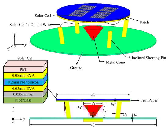
Figure 1.
Structure of the proposed antenna with a solar cell. Dimensions: h1 = 1 mm, h2 = 12 mm, h3 = 1 mm, h4 = 3 mm, d1 = 18.4 mm, d2 = 1.4 mm, d3 = 120 mm, d4 = 70 mm, d5 = 4 mm, α = 10°.
The discone antenna can achieve broadband operation when its profile height is comparable to one-eighth of a wavelength. In order to further reduce the profile of the antenna, a top-loaded antenna was proposed [20,21,22,23]. In this paper, an improved discone antenna with a loaded patch and shorting pins is proposed to reduce the profile of the antenna. The operating frequency range of the antenna can be divided into two parts. The metal cone radiates as a monopole working at higher frequencies. At lower frequencies, the patch and shorting pins function as the radiator, which is fed by the metal cone. Thus, by controlling the size of the patch and the shorting pins, the lowest operating frequency of the antenna can be controlled. Figure 2 compares the simulated S-parameters with and without the patch and shorting pins. It can be seen that without the structure, the lowest resonant frequency is around 3 GHz. When the structure is introduced, the lowest resonant frequency is reduced to 1.6 GHz. To better understand the working principle, Figure 3 illustrates the surface current of the antenna at 1.6 and 3 GHz, respectively. As shown, the surface current is larger at 1.6 GHz than at 3 GHz. This proves that the shorting pins are the main radiator.
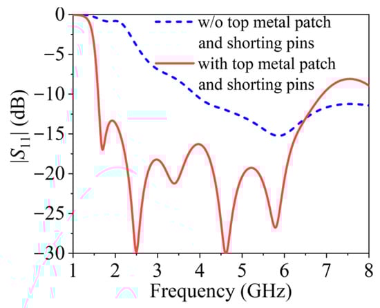
Figure 2.
Simulated S-parameters of the antenna with and without the top metal patch and shorting pins.
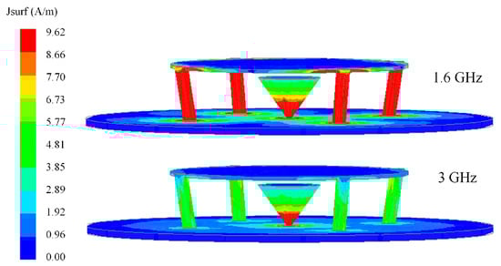
Figure 3.
Simulated surface current distribution of the proposed antenna.
The shorting pins are set at the edge of the patch to lead out the wire of the solar cell. The DC output wires of the solar cell are routed through the hollow center of the shorting pins. So, the wires would not couple to the electromagnetic fields. Another function of these pins is to work as the upholder of the top metal patch. According to the above analysis, the four shorting pins have an effect on the low frequency of the antenna. Figure 4a shows the simulated |S11| of the antenna when the diameter of the shorting pins d5 changes. It can be seen that the lowest resonant frequency of the antenna moves to a lower frequency as d5 decreases. The shorting pins are inductive. As the d5 decreases, the inductance increases. Thus, the lowest resonant frequency decreases. By adding the shorting pins, a frequency resonance at around 1.6 GHz is formed. In our design, the frequency range aims to cover 1.8 to 3.6 GHz. So, d5 = 4 mm is selected to have a good impedance bandwidth. Moreover, the shorting pins were designed to be inclined to adjust the antenna’s impedance to 50 Ω across a broad bandwidth. Figure 4b shows simulated |S11| of the proposed antenna as a function of the shorting pins’ inclination angle α. As shown, when the angle changes from 0° to 20°, the bandwidth of the antenna is almost unchanged. As shown in Figure 4b, as α decreases, |S11| degrades in the 1.6–2.5 GHz and 4.5–6 GHz bands but gets better between 2.5 and 4.5 GHz. Through comprehensive evaluation, α = 10° maintains a consistently low |S11| across all frequencies. Therefore, α = 10° is selected.
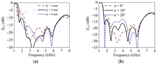
Figure 4.
Simulated S-parameter of the antenna varies with the shorting pins’ design parameters. (a) d5. (b) α.
As established in the preceding analysis, the patch functions as a dominant radiator at lower frequencies, structurally enabling reduction of the antenna’s profile height. Figure 5a shows the simulated |S11| of the proposed antenna versus the diameter of the patch d3. As shown, when d4 increases, the lowest resonant frequency of the antenna decreases, which would benefit from reducing the profile of the antenna. Additionally, the patch is chosen to fit the solar cell’s dimensions. Thus, d4 = 70 mm is chosen as the diameter of the patch. On the other hand, the size of the ground plane also plays an important role in the working frequency of the antenna. Figure 5b shows the simulated |S11| of the proposed antenna versus the diameter of the ground plane d3. As shown, the lowest resonant frequency occurs at approximately 2 GHz when d3 = 110 mm. Increasing d3 to 120 mm or 130 mm shifts this frequency downward to about 1.6 GHz. Consequently, d3 = 120 mm represents the optimal choice for antenna miniaturization.
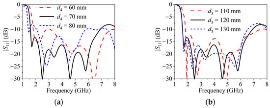
Figure 5.
Simulated S-parameter of the antenna varies with the diameter of the patch and the ground plane. (a) d4. (b) d3.
Figure 6 shows that the simulated |S11| of the proposed antenna varies with the cone’s diameter d1 and height h2. As shown in Figure 6a, d1 has a minor impact on the low-frequency resonant frequency of the antenna, but a more significant effect on the high-frequency performance. Additionally, different values of d1 influence the impedance matching of the antenna across the entire frequency band. When d1 = 16.4 mm, the reflection coefficient of the antenna at 2 GHz deteriorates, and the operational bandwidth also decreases. Although a wider bandwidth is achieved when d1 = 20.4 mm, the reflection coefficient at 2 GHz is minimized when d1 = 18.4 mm. This is because 2 GHz falls within the operational frequency range of the hybrid energy harvesting system. Thus, d1 = 18.4 mm is selected for our design. From Figure 6b, it can be observed that h2 affects the reflection coefficient of the antenna across the entire frequency band. When h2 = 12 mm, the reflection coefficient performance is optimal. Therefore, h2 = 12 mm is chosen.
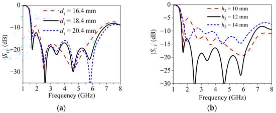
Figure 6.
Simulated S-parameter of the antenna varies with the cone’s design parameters. (a) d1. (b) h2.
Figure 7 plots simulated |S11| of the antenna with different air gaps between the metal cone and patch h4. When h4 increases, the couple between the metal cone and the metal patch decreases, which has an effect on the impedance matching of the antenna. The simulated results show that when h4 = 3 mm, the antenna has a good impedance matching across a broad bandwidth, with |S11| remaining below −15 dB from 2.12 to 6.29 GHz.
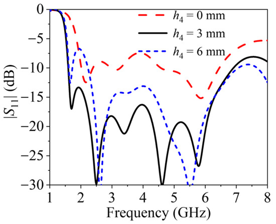
Figure 7.
Simulated S-parameter of the antenna varies with the air gap h4.
The rectenna is designed to operate across the 1.6–3.6 GHz band. Figure 8 shows the simulated 3D radiation patterns at 1.6, 2.6, and 3.6 GHz, respectively. As shown, the antenna gain is 1 dBi at 1.6 GHz, 4.3 dBi at 2.6 GHz, and 6.6 dBi at 3.6 GHz, respectively. It is noted that the antenna exhibits omnidirectional radiation characteristics in the xoy plane, which enables it to harvest RF energy from all directions. The antenna patterns shift upwards, away from the ground plane, when the working frequency is high.
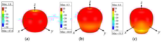
Figure 8.
Simulated 3D radiation patterns of the proposed antenna with a solar cell. (a) 1.6 GHz. (b) 2.6 GHz. (c) 3.6 GHz.
To verify the design concept, a discone antenna integrated with a solar cell is fabricated, as shown in Figure 9. The metal antenna is implemented by selective laser melting (SLM) metal 3D printing technology using AlSi10Mg material. The accuracy is ±0.2 mm. Figure 10 compares the simulated and measured |S11| of the proposed antenna with and without the solar cell. In the simulation, the solar cell is modeled as a metal plane, an n-p silicon layer, and two electrode layers. And fish paper is placed between the antenna’s patch and the solar cell to provide electrical insulation. Thus, the interaction of the solar cell and the antenna can be considered in the simulation. The thickness of the aluminum substrate and n-p silicon is 0.035 and 0.2 mm. Then, the n-p silicon layer was simplified in the simulation, with εr = 11.9, tanδ = 2.2, and σ = 13.5 S/m [19]. In Figure 10, both the simulation and measurement results can prove that the solar cell has negligible effect on the working frequency of the antenna. Moreover, the measured bandwidth of the antenna is from 1.56 to 6.63 GHz regardless of solar cell integration, while the simulated bandwidth is from 1.59 to 6.94 GHz under both conditions. The measured bandwidth is a little narrower than the simulated one, which is likely attributed to fabrication errors in the antenna manufacturing process.
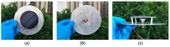
Figure 9.
Photograph of the fabricated antenna integrated with a solar cell. (a) Top view. (b) Bottom view. (c) Side view.
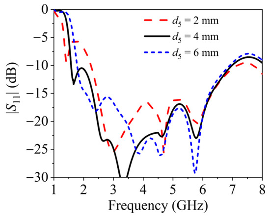
Figure 10.
Simulated and measured S-parameters of the proposed antenna with and without the solar cell.
Figure 11 plots the simulated and measured gain of the antenna with and without the integrated solar cell when φ = 0° and θ = 45° as well as φ = 45° and θ = 45°, respectively. The antenna test was conducted in a microwave anechoic chamber. As shown in the simulation, the gains of the antenna with and without the solar cell are nearly the same. In Figure 11a, when φ = 0° and θ = 45°, the simulated gain of the antenna, regardless of the solar cell, is from 0.4 to 4.6 dBi, while the measured gain is from 0 to 4.4 dBi without the solar cell, and it is from −0.1 to 4.5 dBi with the solar cell. In Figure 11b, when φ = 45° and θ = 45°, the simulated gain of the antenna, regardless of the solar cell, is from 0.5 to 5.8 dBi, while the measured gain is from 0.2 to 5.6 dBi without the solar cell, and it is from −0.3 to 4.6 dBi with the solar cell. The measured gain is slightly lower than the simulated one, the discrepancy being potentially attributable to measurement errors.
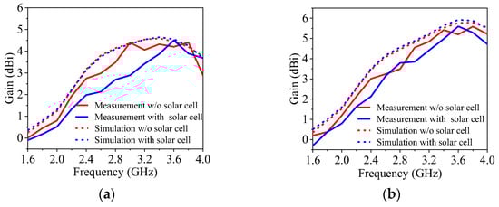
Figure 11.
Simulated and measured gain of the proposed antenna with and without the integrated solar cell. (a) φ = 0°, θ = 45°. (b) φ = 45°, θ = 45°.
The gain deviation in the azimuthal plane (θ = 90°) at 1.6, 2.6, and 3.6 GHz is shown in Figure 12, which illustrates that the deviation increases with an increase in frequency. The deviations in the gain of the antenna are 1.41, 2.18, and 10.24 dB, respectively, at the corresponding frequencies. The deviation in gain at 3.6 GHz is significantly greater, which may be attributed to the measurement errors. The simulated and measured 2D radiation patterns of the antenna with the solar cell at three different frequencies are depicted in Figure 13. The measured radiation patterns agree well with the simulated ones. The 3 dB beamwidths of the antenna are 96°, 53°, and 35° at 1.6, 2.6, and 3.6 GHz, respectively, in the φ = 0° plane, while the corresponding beamwidths are 73°, 49°, and 31° in the φ = 45° plane.
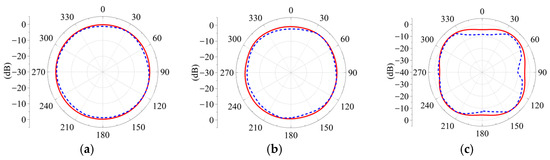
Figure 12.
Simulated and measured 2D radiation patterns of the proposed antenna with a solar cell when θ = 90°. (a) 1.6 GHz. (b) 2.6 GHz. (c) 3.6 GHz.
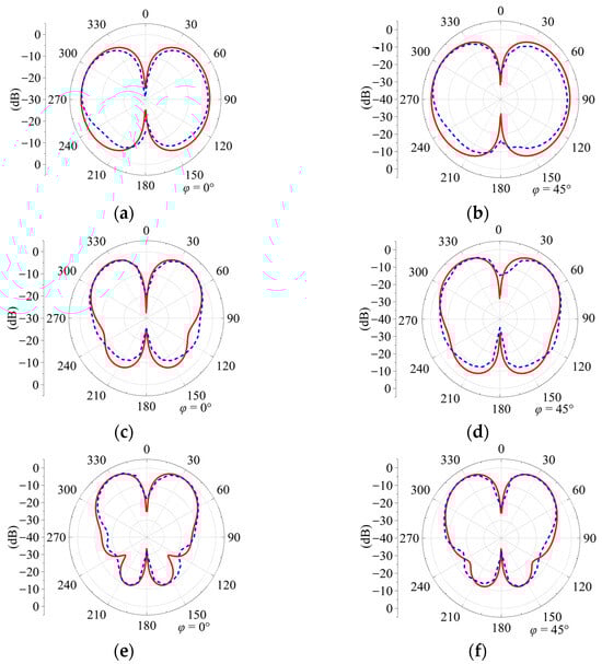
Figure 13.
Simulated and measured 2D radiation patterns of the proposed antenna with a solar cell. (a) 1.6 GHz, φ = 0°. (b) 1.6 GHz, φ = 45°. (c) 2.6 GHz, φ = 0°. (d) 2.6 GHz, φ = 45°. (e) 3.6 GHz, φ = 0°. (f) 3.6 GHz, φ = 45°.
3. Broadband Rectifier
Figure 14 depicts the schematic and layout of the proposed broadband rectifier circuit with all design parameters. As shown in Figure 14a, the circuit was designed based on the voltage doubler topology to increase the output DC voltage and achieve a broad bandwidth [24]. The rectifier circuit comprises a single-stub matching network (TL1 and TL2), a DC block capacitor (C1), two Schottky diodes (SMS7630-040LF), a bypass capacitor (CL) and a load (RL). The load resistance RL is set to be 1 kΩ. The characteristic impedance and electrical length of the ith transmission line TLi is Z0i and θi (i = 1, 2). In Figure 14b, the transmission line TL2 is folded to minimize the circuit size.
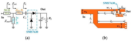
Figure 14.
Structure of the proposed rectifier circuit. (a) Schematic. (b) Layout. Dimensions: w0 = 2.2, w1 = 0.5, w2 = 2.4, l1 = 5.2, l2 = 6, l3 = 13.1, l4 = 3 (unit: mm).
To design the broad-bandwidth rectifier, firstly, the load part input impedance ZL is obtained by simulation. The simulated ZL from 1 to 4 GHz is shown in Figure 15. It can be seen that ZL is capacitive, with the real part ranging from 26.5 to 135.7 Ω and the imaginary part ranging from −109.9 to −36.9 Ω. The locus is outside the circle of VSWR = 2, which indicates that ZL is not well matched to 50 Ω, resulting in a high reflection coefficient. As a result, the RF to DC PCE of the rectifier would decrease. The aim of the matching network is to compress the input impedance of the rectifier into the circle of VSWR = 2 across a wide bandwidth. In this design, the bandwidth of the rectifier is defined as ranging from fL = 1.6 GHz to fH = 3.6 GHz.
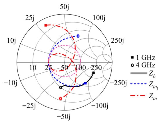
Figure 15.
Impedance locus over 1 to 4 GHz with an input power level of 5 dBm.
As shown in Figure 15, there are two steps to designing the wideband matching network. In the first step, the locus of Zin1 can be obtained from the clockwise rotation of the ZL locus by a series transmission line, TL1. Before TL1 is introduced, ZL = (78.95 − j98.2) Ω at 1.6 GHz and ZL = (31.8 − j40.8) Ω at 3.6 GHz from the simulated results in Figure 15. After TL1 is introduced, we obtain
If the real part of Zin1 is labeled Rin1, while the imaginary part is Xin1, then it should satisfy the following requirement:
This indicates that the input impedance Zin1 at 1.6 and 3.6 GHz is a complex conjugate. By solving Equations (1)–(3), we obtain Z01 = 79.5 Ω and θ1 = 45.5° @ 2.6 GHz. Thus, Zin1(fL) can be obtained as (33.3 − j44.4) Ω, while Zin1(fH) is (33.3 + j44.4) Ω.
The series microstrip line (TL1) is followed by a shunt-connected short-circuited stub (TL2) to further the impedance match. The admittance of the shunt-shorted stub is given by
The reflection coefficient of the rectifier can be expressed by
Let VSWR = 2 at 1.6 and 3.6 GHz. Then, we get two equations from Equation (5). And there are two variables Z02 and θ2. By solving those two equations, we get Z02 = 36 Ω and θ2 = 90.7° @ 2.6 GHz. As shown in Figure 15, we get Zin(fL) = (78.8+j32.7) Ω and Zin(fH) = (73.6 − j37.4) Ω. Those two points are in the circle of VSWR = 2, which defines the bandwidth of the rectifier. Finally, the layout of the circuit is optimized to get a better reflection coefficient and PCE over a broad bandwidth.
To verify the design concept, the proposed broadband rectifier circuit shown in Figure 16 is fabricated and measured. The substrate employed in the design is 0.8 mm F4B, with a relative dielectric constant of 2.6 and loss tangent of 0.002. Two Schottky diodes, SMS7630, are used. The values of the DC block capacitor and bypass capacitor are 62 and 820 pF. The output load RL is 1 kΩ. The dimensions of the rectifier are 21 × 14 mm2. In the experiment, A microwave source is used to generate RF power Pin. And the voltage on the load Vout is measured by a multimeter. The PCE can be calculated by
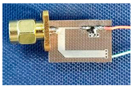
Figure 16.
Prototype of the fabricated rectifier circuit.
Figure 17 illustrates the simulated and measured |S11| and PCE versus frequency at different input power levels, respectively. It can be seen that the simulated results agree well with the measured ones, except that the measured PCE has slight degradation. This is due to the greater actual losses in the rectifier circuit compared to simulation predictions. In the measurement, at an input power level of 10 dBm, the rectifier maintains an efficiency exceeding 55% across the 1.5 to 3.6 GHz band, with a fractional bandwidth (FBW) of 82.3%. At an input power of 5 dBm, it maintains an efficiency exceeding 50% across the 1.4 to 3.6 GHz band featuring an FBW of 88% and |S11| below −10 dB across the 1.65 to 3.67 GHz band featuring an FBW of 75.9%. When the input power level reduces to 0 dBm, the measured PCE remains above 40% across 1.4 to 3.6 GHz. In addition, at an input power level of −5 dBm, the efficiency remains above 30% over 1.5 to 3.6 GHz. Moreover, the PCE reaches its peak value at 3.3 GHz.
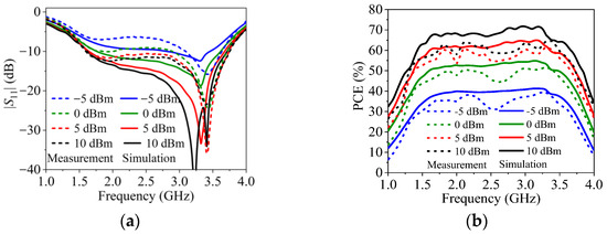
Figure 17.
Simulated and measured |S11| and PCE versus frequency at different values of input power. (a) |S11|. (b) PCE.
Figure 18 plots the simulated and measured efficiency and output DC voltage versus input power level at 1.4, 2.5, 3.3, and 3.6 GHz, respectively. As shown, the measured results are slightly lower than the simulation ones at all measured frequencies. This may be due to the excursion of the diode parameters between the simulation model and the actual device. At 1.4, 2.5, 3.3, and 3.6 GHz, the rectifier has reached its peak efficiencies of 54.9%, 60.2%, 66%, and 58.3%, respectively, while the corresponding DC output voltages are 2.63, 3.89, 3.63, and 3.41 V at an input power level of 11, 14, 13, and 14 dBm, respectively. It can be observed that the output DC voltage increases stably when the input power is fed. The observed efficiency and DC output voltage increase compared with the simulation at a high power level is principally caused by the higher reverse breakdown voltage of the actual diode.
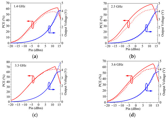
Figure 18.
Simulated and measured PCE and output voltage versus input power level with a load of 1 kΩ. (a) 1.4 GHz. (b) 2.5 GHz. (c) 3.3 GHz. (d) 3.6 GHz. (Solid line: simulation results; dashed line: measurement results.)
Figure 19 presents the measured PCE and output DC voltage versus load resistance at 1.4, 2.5, 3.3, and 3.6 GHz, respectively, when the input power is 5 dBm. The measured PCE reaches its peak value when the load is 0.95, 1, 1.4, and 1.7 kΩ, respectively. The measured curves exhibit a trend consistent with the simulated curves, except for a slight deviation. This may be caused by the deviation of the diode’s simulation model and actual device.
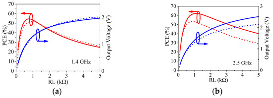
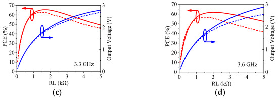
Figure 19.
Simulated and measured PCE and output voltage versus load resistance at an input power of 5 dBm.(a) 1.4 GHz. (b) 2.5 GHz. (c) 3.3 GHz. (d) 3.6 GHz. (Solid line: simulation results; dashed line: measurement results.)
Table 1 compares the performance of the proposed broadband rectifier against rectifiers reported in the literature. In Table 1, all rectifiers utilize diodes with comparable performance (SMS7630 and HSMS2850) for low RF power harvesting. All the previous works exhibit a bandwidth below 85% and the highest operating frequency below 3.5 GHz. In contrast, the proposed rectifier circuit achieves the widest FBW of 88%, the highest operating frequency of 3.6 GHz, and a relatively higher peak PCE of 66%. Additionally, it features a more compact physical size. These attributes make it suitable for ambient WEH applications.

Table 1.
Comparison of the performance of the proposed rectifier with those reported in previous publications.
4. Rectenna with Integrated Solar Cell and Measurement Results
The current–voltage (I-V) curve of the solar cell under standard global AM1.5 illumination conditions is shown in Figure 20. The measurements show an open circuit voltage of 5.415 V and a short circuit current of 37 mA. The maximum power is 135.1 mW, corresponding to 4.17 V and 32.3 mA.
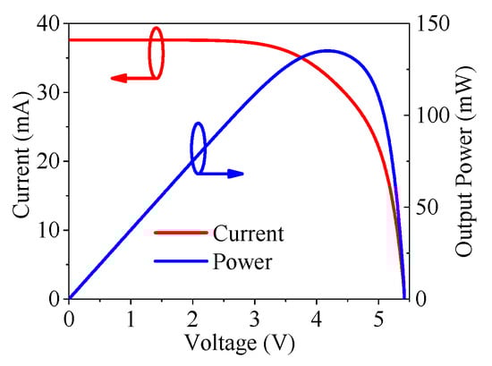
Figure 20.
The measured I-V characteristics of the solar cell.
Figure 21 illustrates the measurement setup of the RF-solar energy harvesting system. The rectenna under test is placed 1 m away from the transmitting antenna. In this design, we utilize a polycrystalline silicon solar cell with a diameter of 70 mm to harvest solar energy. The solar cell is placed above the metal patch so that the solar cell is not completely covered by any object. As shown, the test setup employs a standard gain horn antenna as the transmitting antenna. A microwave source is used to generate microwave signal and then it is amplified by a broadband power amplifier. The 30 dB coupler and power meter are used to measure the transmitting power of the transmitting antenna. The output power of the solar cell and rectenna is combined by a parallel connection [13]. It is assumed that their output DC power will combine. In the measurement, the antenna is connected to a power meter to measure the received microwave power, which is also the input power of the rectifier. Then, the output DC power is measured by a multimeter. This testing method has been widely used in previously published papers [31,32].
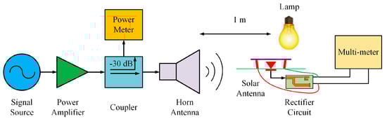
Figure 21.
Hybrid solar rectenna measurement setup.
In the measurement, the output voltage of the solar cell is 0.64 V with a load of 1 kΩ. Figure 22 compares the output DC voltage and the power versus input power level in three energy harvesting situations. At 1.6, 2.6, and 3.6 GHz, the output voltage of the rectenna varies from 0.015 to 4.5 V, 0.0124 to 4.6 V, and 0.017 to 4.62 V, respectively, when the input power level ranges from −20 to 16 dBm with a load of 1 kΩ. When the input power of the rectenna reaches 0 dBm, the output power of the rectenna approaches what the solar cell generates at three frequencies. It can be observed that the output DC power of the hybrid energy harvester at the three frequencies is 20.25, 19.89, and 18.23 mW, which is almost 49 times that of the single solar cell’s 0.049 mW output power at an input RF power of 16 dBm. The measured results prove that the solar cell and the rectenna can work together, and both contribute to the output DC power.
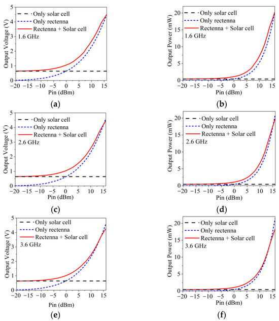
Figure 22.
Measured output voltage and power of different energy harvesters versus the input power level. (a) Output voltage, 1.6 GHz. (b) Output power, 1.6 GHz. (c) Output voltage, 2.6 GHz. (d) Output power, 2.6 GHz. (e) Output voltage, 3.6 GHz (f) Output power, 3.6 GHz.
Figure 23 illustrates the test scenario of the hybrid energy harvester and only the rectifier during the daytime. The experiment was conducted under conditions with a clarity index close to 1. A temperature and humidity sensor operating at 3 V was employed as the load. Due to the low ambient RF energy density and temporal signal variations in outdoor environments, a power management unit (PMU) is needed, which incorporates a bq25504 chip that can boost the output voltage and a 50 mF supercapacitor that can store the harvested energy. Figure 23a shows that during daytime, the solar cell and rectenna can work together to enable the sensor to operate, while Figure 23b demonstrates that at night, the rectenna alone can function to keep the sensor working.
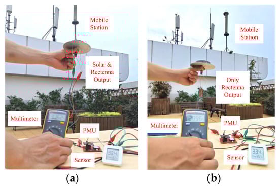
Figure 23.
Hybrid energy harvester test scenario outdoors. (a) Solar cell and rectenna. (b) Rectenna.
Table 2 presents the performance of the proposed broadband omnidirectional rectenna integrated with a solar cell compared to other previous works. As plotted in Table 2, the reported hybrid energy harvester can work at only a single frequency or dual band, while the hybrid energy harvester proposed in this work has a wide bandwidth of 1.6 to 3.6 GHz, which can harvest more RF signals with different frequencies. The PCE of the rectenna has a higher PCE than other works. And the proposed hybrid energy harvester can produce more DC power compared with other works. Furthermore, the rectenna’s omnidirectional radiation pattern enables it to capture electromagnetic waves arriving from all directions, while the solar cell on the top can effectively receive solar energy from above. Effective spatial isolation between the two energy harvesting mechanisms can be achieved. These advantages make the rectenna proposed in this paper highly suitable for scenarios where energy harvesting is used to power sensors.
Table 2.
Comparison of the performance of the proposed solar rectenna with those reported in previous publications.
5. Conclusions
This paper proposes a broadband omnidirectional rectenna integrated with a solar cell for simultaneous harvesting of solar and ambient RF energy. By strategically configuring the structures of the antenna and the solar cell, the issue of interaction between the two components is effectively resolved. The proposed antenna integrated with a solar cell features a broad bandwidth and has undergone dimensional optimization for low profile. Its omnidirectional radiation pattern facilitates the rectenna’s ability to capture incoming EM waves from all azimuthal directions. The designed rectifier circuit achieves a PCE exceeding 50% across the 1.4 to 3.6 GHz band. When integrated with the solar antenna, the system demonstrates effective microwave energy harvesting ability, thereby compensating for the inherent limitation of solar cells during nighttime. The proposed solar rectenna holds significant potential for powering low-power IoT devices. Although the single antenna unit harvester presented here is sufficient for low-power applications like IoT sensors, its output power is inherently limited. To address higher-power requirements and further enhance system performance, future work will focus on developing an array configuration based on the proposed antenna unit cell.
Author Contributions
Conceptualization, F.C. and W.N.; methodology, F.C. and W.N.; validation, B.-Y.C., H.-P.L., and F.C.; formal analysis, B.-Y.C. and F.C.; data curation, B.-Y.C., H.-P.L., and F.C.; writing—original draft preparation, F.C. and B.-Y.C.; writing—review and editing, W.N.; supervision, W.N.; project administration, F.C. All authors have read and agreed to the published version of the manuscript.
Funding
This work was supported by the Foundation of National Key Laboratory under Grant 2023-JCJQ-LB-051-06.
Data Availability Statement
The original contributions presented in the study are included in the article. Further inquiries can be directed to the corresponding author.
Conflicts of Interest
Author Wang Ni was employed by the company Tianjin Institute of Power Sources. The remaining authors declare that the research was conducted in the absence of any commercial or financial relationships that could be construed as a potential conflict of interest.
Abbreviations
The following abbreviations are used in this manuscript:
| EM | electromagnetic |
| WEH | wireless energy harvesting |
| DC | direct current |
| IoT | Internet of Things |
| ISM | industrial, scientific, medical |
| PET | polyethylene terephthalate |
| EVA | ethylene vinyl acetate |
| SLM | selective laser melting |
| FBW | fractional bandwidth |
| PMU | power management unit |
| RF | radio frequency |
| PCE | power conversion efficiency |
| CRLH | composite right-/left-handed |
References
- Piñuela, M.; Mitcheson, P.D.; Lucyszyn, S. Ambient RF Energy Harvesting in Urban and Semi-Urban Environments. IEEE Trans. Microw. Theory Tech. 2013, 61, 2715–2726. [Google Scholar] [CrossRef]
- Du, C.-H.; Cheng, F.; Yang, Y.; Zhu, H.; Gu, C. Omnidirectional Flexible Tri-Band Rectenna with Eliminated Matching Circuit for Ambient RF Energy Harvesting. IEEE Trans. Microw. Theory Tech. 2025, 73, 674–686. [Google Scholar] [CrossRef]
- Zhang, Y.; Shen, S.; Chiu, C.Y.; Murch, R. Hybrid RF-Solar Energy Harvesting Systems Utilizing Transparent Multiport Micromeshed Antennas. IEEE Trans. Microw. Theory Tech. 2019, 67, 4534–4546. [Google Scholar] [CrossRef]
- Dreyer, P.; Morales-Masis, M.; Nicolay, S.; Ballif, C.; Perruisseau-Carrier, J. Copper and Transparent-Conductor Reflectarray Elements on Thin-Film Solar Cell Panels. IEEE Trans. Antennas Propag. 2014, 62, 3813–3818. [Google Scholar] [CrossRef]
- Peter, T.; Rahman, T.A.; Cheung, S.W.; Nilavalan, R.; Abutarboush, H.F.; Vilches, A. A Novel Transparent UWB Antenna for Photovoltaic Solar Panel Integration and RF Energy Harvesting. IEEE Trans. Antennas Propag. 2014, 62, 1844–1853. [Google Scholar] [CrossRef]
- Xi, B.; Liang, X.; Chen, Q.; Wang, K.; Geng, J.; Jin, R. Optical Transparent Antenna Array Integrated with Solar Cell. IEEE Antennas Wirel. Propag. Lett. 2020, 19, 457–461. [Google Scholar] [CrossRef]
- Rashidian, A.; Shafai, L.; Shafai, C. Miniaturized Transparent Metallodielectric Resonator Antennas Integrated with Amorphous Silicon Solar Cells. IEEE Trans. Antennas Propag. 2017, 65, 2265–2275. [Google Scholar] [CrossRef]
- Yurduseven, O.; Smith, D.; Elsdon, M. A transparent meshed solar monopole antenna for UWB applications. In Proceedings of the 8th European Conference on Antennas and Propagation (EuCAP 2014), The Hague, The Netherlands, 6–11 April 2014; pp. 2145–2149. [Google Scholar]
- Cambero, E.V.V.; da Paz, H.P.; da Silva, V.S.; de Araújo, H.X.; Casella, I.R.S.; Capovilla, C.E. A 2.4 GHz Rectenna Based on a Solar Cell Antenna Array. IEEE Antennas Wirel. Propag. Lett. 2019, 18, 2716–2720. [Google Scholar] [CrossRef]
- Luo, Y.; Lai, J.; Yan, N.; An, W.; Ma, K. Codesign of Single-Layer Dual-Polarized Dual Compressed High-Order Modes Differentially Fed Patch Antenna and Solar Cells for Green Communication. IEEE Trans. Antennas Propag. 2022, 70, 2289–2294. [Google Scholar] [CrossRef]
- Long, H.; Cheng, F.; Yu, S.; Gu, C.; Huang, K. High-efficiency broadband rectifier with compact size for wireless power transfer. Microw. Opt. Technol. Lett. 2022, 64, 2007–2013. [Google Scholar] [CrossRef]
- Bairappaka, S.K.; Ghosh, A.; Kaiwartya, O.; Aljaidi, M.; Cao, Y.; Kharel, R. A Novel Design of Broadband Circularly Polarized Rectenna with Enhanced Gain for Energy Harvesting. IEEE Access 2024, 12, 65583–65594. [Google Scholar] [CrossRef]
- Chandrasekaran, K.T.; Agarwal, K.; Nasimuddin; Alphones, A.; Mittra, R.; Karim, M.F. Compact Dual-Band Metamaterial-Based High-Efficiency Rectenna: An Application for Ambient Electromagnetic Energy Harvesting. IEEE Antennas Propag. Mag. 2020, 62, 18–29. [Google Scholar] [CrossRef]
- Sang, J.; Qian, L.; Wang, X.; Shi, G. A dual-band omnidirectional rectenna for radio-frequency energy harvesting applications. Microelectron. J. 2025, 256, 106533. [Google Scholar] [CrossRef]
- Wan, S.; Lu, P.; Yin, D.; Guan, X.; Ni, W. A compact hybrid solar and electromagnetic energy harvester at 2.45 GHz microstrip rectenna. AEU Int. J. Electron. Commun. 2023, 172, 154941. [Google Scholar] [CrossRef]
- Bito, J.; Bahr, R.; Hester, J.G.; Nauroze, S.A.; Georgiadis, A.; Tentzeris, M.M. A Novel Solar and Electromagnetic Energy Harvesting System with a 3-D Printed Package for Energy Efficient Internet-of-Things Wireless Sensors. IEEE Trans. Microw. Theory Tech. 2017, 65, 1831–1842. [Google Scholar] [CrossRef]
- Collado, A.; Georgiadis, A. Conformal Hybrid Solar and Electromagnetic (EM) Energy Harvesting Rectenna. IEEE Trans. Circuits Syst. I Regul. Pap. 2013, 60, 2225–2234. [Google Scholar] [CrossRef]
- Yu, B.-Y.; Wang, Z.-H.; Ju, L.; Zhang, C.; Liu, Z.-G.; Tao, L.; Lu, W.-B. Flexible and Wearable Hybrid RF and Solar Energy Harvesting System. IEEE Trans. Antennas Propag. 2022, 70, 2223–2233. [Google Scholar] [CrossRef]
- Wei, Z.; Xue, H.; Li, Y.; Zhao, S.; Chen, Z.; Li, L. A Hybrid RF and Solar Integrated Energy Harvesting System Using Optically Transparent Metasurface. IEEE Trans. Antennas Propag. 2025, 73, 920–927. [Google Scholar] [CrossRef]
- Gangi, A.; Sensiper, S.; Dunn, G. The characteristics of electrically short, umbrella top-loaded antennas. IEEE Trans. Antennas Propag. 1965, 13, 864–871. [Google Scholar] [CrossRef]
- Aten, D.W.; Haupt, R.L. A Wideband, Low Profile, Shorted Top Hat Monocone Antenna. IEEE Trans. Antennas Propag. 2012, 60, 4485–4491. [Google Scholar] [CrossRef]
- Liu, A.; Lu, Y. A Superwide Bandwidth Low-Profile Monocone Antenna with Dielectric Loading. IEEE Trans. Antennas Propag. 2019, 67, 4173–4177. [Google Scholar] [CrossRef]
- Amert, A.K.; Whites, K.W. Miniaturization of the Biconical Antenna for Ultrawideband Applications. IEEE Trans. Antennas Propag. 2009, 57, 3728–3735. [Google Scholar] [CrossRef]
- Yu, S.; Cheng, F.; Gu, C.; Wang, C.; Huang, K. Compact and Efficient Broadband Rectifier Using T-type Matching Network. IEEE Microw. Wirel. Compon. Lett. 2022, 32, 587–590. [Google Scholar] [CrossRef]
- Park, H.S.; Hong, S.K. Broadband RF-to-DC Rectifier with Uncomplicated Matching Network. IEEE Microw. Wirel. Compon. Lett. 2020, 30, 43–46. [Google Scholar] [CrossRef]
- Joseph, S.D.; Huang, Y.; Hsu, S.S.H. Transmission Lines-based Impedance Matching Technique for Broadband Rectifier. IEEE Access 2021, 9, 4665–4672. [Google Scholar] [CrossRef]
- He, H.; Zhou, Y.; He, Z.; Feng, Y.; Liu, C. High-Efficiency Octave Bandwidth Rectifier for Electromagnetic Energy Harvesting. IEEE Microw. Wirel. Technol. Lett. 2025, 35, 549–552. [Google Scholar] [CrossRef]
- Wu, Y.; Wang, J.; Liu, Y.; Li, M. A Novel Wideband Rectifier Design with Two-stage Matching Network for Ambient Wireless Energy Harvesting. In Proceedings of the 2018 Progress in Electromagnetics Research Symposium (PIERS-Toyama), Toyama, Japan, 1–4 August 2018; pp. 1351–1354. [Google Scholar]
- Liu, W.; Huang, K.; Wang, T.; Hou, J.; Zhang, Z. A Compact Ultra-Broadband RF Rectifier Using Dickson Charge Pump. IEEE Microw. Wirel. Compon. Lett. 2022, 32, 591–594. [Google Scholar] [CrossRef]
- Kimionis, J.; Collado, A.; Tentzeris, M.M.; Georgiadis, A. Octave and Decade Printed UWB Rectifiers Based on Nonuniform Transmission Lines for Energy Harvesting. IEEE Trans. Microw. Theory Tech. 2017, 65, 4326–4334. [Google Scholar] [CrossRef]
- Sun, H.; Guo, Y.-X.; He, M.; Zhong, Z. Design of a High-Efficiency 2.45-GHz Rectenna for Low-Input-Power Energy Harvesting. IEEE Microw. Wirel. Compon. Lett. 2012, 11, 929–932. [Google Scholar]
- Cheng, F.; Wang, H.-Y.; Ni, W.; Chen, X.; Yang, Y.; Huang, K. Single-Layer Rectenna Array with Integrated Matching Circuit for Wireless Power Transfer. IEEE Trans. Antennas Propag. 2025, 73, 4466–4475. [Google Scholar] [CrossRef]
Disclaimer/Publisher’s Note: The statements, opinions and data contained in all publications are solely those of the individual author(s) and contributor(s) and not of MDPI and/or the editor(s). MDPI and/or the editor(s) disclaim responsibility for any injury to people or property resulting from any ideas, methods, instructions or products referred to in the content. |
© 2025 by the authors. Licensee MDPI, Basel, Switzerland. This article is an open access article distributed under the terms and conditions of the Creative Commons Attribution (CC BY) license (https://creativecommons.org/licenses/by/4.0/).