Article

Tracking the Fuel Trajectory from Each Injector for Fuel–Air Mixing in Supersonic Flows

by
Qiongyao Qin
*,
Yanhan Yang
,
Yidong Liu
,
Mingze Yuan
and
Jianzhong Li
*
College of Energy and Power Engineering, Nanjing University of Aeronautics and Astronautics, Nanjing 210016, China
*
Authors to whom correspondence should be addressed.
Energies 2025, 18(17), 4664; https://doi.org/10.3390/en18174664
Submission received: 3 August 2025 / Revised: 19 August 2025 / Accepted: 1 September 2025 / Published: 2 September 2025

Abstract

Fuel injection and mixing remain a critical challenge in the development of supersonic propulsion systems. The efficiency of both mixing and combustion significantly influences the overall performance of these systems, underscoring the importance of optimizing fuel injection strategies. Injector arrays are extensively employed in such propulsion systems; however, conventional design methodologies predominantly focus on global mixing efficiency, neglecting injector-specific performance metrics. This research introduces a fuel trajectory tracing methodology, wherein hydrogen from each injector is treated as a distinct species, despite having identical physical and chemical properties. This approach enables the tracking of hydrogen transport and mixing within supersonic flows. The methodology has been demonstrated to accurately capture the mass fraction distribution of hydrogen from individual injectors without perturbing the flow field. Based on these distributions, injector-specific mixing and combustion efficiencies can be quantified, providing valuable insights for optimizing injector configurations and enhancing propulsion system performance.

1. Introduction

A technical challenge facing scramjet development is how to achieve fuel injection and mixing without severe shock losses [1]. Rapid and uniform mixing can guarantee flame stabilization and combustion efficiency [2]. Thus, it is of great importance to investigate mixing strategies for fuel injection. Injector arrays are widely used for fuel injection in supersonic combustors [2,3,4]. Conventional design methodologies predominantly focus on global mixing efficiency, neglecting injector-specific performance metrics. In this study, we adopted a fuel trajectory tracing method that can distinguish the hydrogen from each injector. Based on this method, the mixing efficiency and the combustion efficiency of each injector can be evaluated separately, which is of significance in guiding the design and manufacture [5] of injectors.
The residence time of the fuel in the supersonic propulsion system is of the millisecond order. To achieve stable and efficient combustion, an efficient fuel injector and flame holder are necessary [2]. Many fuel injector strategies have been explored including struts, transverse jets, and others [2,3,4,6]. Significant efforts have been made to improve the mixing efficiency and reduce the total pressure loss in fuel injection; among others, Huang et al. have conducted many valuable investigations [7,8,9]. Typically, Huang et al. studied the jet-to-crossflow ratio in the mixing and combustion process [7]. Li et al. investigated three mixing enhancement strategies in transverse jet flow fields [8] and a novel injection strategy that combined a micro-ramp with an air porthole [9]. A cavity is widely used to act as a flame holder and to enhance mixing [10,11,12]. Moradi et al. numerically studied the effect of the cavity shape—rectangular, trapezoidal, or circle—on the mixing zone [13]. Similarly, Cai et al. studied the influence of the cavity rear wall height on the mixing characteristic [14], with two cascaded injectors adopted as the fuel injection strategy. Hassanvand et al. conducted numerical simulations to analyze the effects of different jets on the mixing rate in the cavity [15]. The difference between a single fuel jet and two micro fuel jets is discussed in detail.
A strut is widely used as a fuel injector and flame holder, as well [16,17,18,19,20,21,22,23,24]. Kodera et al. conducted a series of studies on an Alternating-Wedge (AW) strut [16]. Different expansion ramp angles were studied, and the ramp angle of 36 deg. performed better than that of 22 deg. [16]. Other features of this type of strut are revealed in their research [17]. Choubey et al. investigated a two-strut scramjet combustor. The combustion efficiency and mixing efficiency were compared between the single-strut and the two-strut configuration [18,19,20]. The effects of the strut injector geometries on the mixing features in the combustor were studied [21,22], and different injection strategies were considered [23] with hydrogen injected from different areas at the rears of the struts. No matter which injection strategy is utilized—wall injection or strut injection, with or without cavity—injector arrays are commonly used [24,25,26]. Moreover, the dynamic behavior of the scramjet combustor system is strongly affected by the mixing efficiency [27]. However, the mixing efficiency of each injector is not available in previous studies.
For the optimization of fuel injection strategies, the most common used evaluation criteria is the global mixing efficiency and the global combustion efficiency. The global performance of an injection strategy may be very good, but the performance of each injector is unavailable under the framework of the traditional criteria. Because the fuel from each injector is the same, it is impossible to determine the parameters for the fuel from each injector. To resolve this problem and to establish a novel evaluation criterion for the fuel injection, a tracing method for the fuel is proposed. A numerical method is established to verify the tracing method. Based on this method, the parameters of the fuel from each injector will be obtained, i.e., the mass fraction distribution.

2. Numerical Methods

2.1. Governing Equations

The two-dimensional Navier–Stokes equations are taken as the governing equations. A tracing species is specified for each injector, so the species diffusion is taken into consideration.
Q t + E x + F y = E υ x + F υ y
Q = ρ 1 , , ρ N , ρ u , ρ v , ρ E T
E = ρ 1 u , , ρ N u , ρ u 2 + p , ρ u v , u ρ E + p T
F = ρ 1 v , , ρ N v , ρ u v , ρ v 2 + p , v ρ E + p T
E υ = ρ D 1 c 1 x , , ρ D N c N x , τ x x , τ x y , u τ x x + v τ x y + q x T
F υ = ρ D 1 c 1 y , , ρ D N c N y , τ x y , τ y y , u τ x y + v τ y y + q y T
The density and the total energy are expressed as follows:
ρ = i = 1 N ρ i
E = h p ρ + 1 2 u 2 + v 2
where h is the specific enthalpy. The equation of state is given by
p = i = 1 N R ρ i M w ,   i T
The Finite Volume Method (FVM) is adopted to solve the Navier–Stokes equations. The AUSM [28,29] is adopted as the flux split scheme. The thermal conductivity and the viscosity are computed from the ideal-gas-mixing law. The mass diffusivity is computed as kinetic theory. The two-equation RNG k ε turbulence model and standard wall function are coupled.

2.2. Tracking the Fuel Trajectory

In the scramjet combustor, the hydrogen from each injector is the same, physically and chemically. In the experimental method, different tracer particles can be added for each injector. However, the physical and chemical properties of the tracer particles are not the same as the fuel. In the numerical method, the tracing for the fuel is easier to accomplish. We define a unique species for each injector. Although the names of the hydrogens from each injector are different, the chemical and physical properties of the hydrogens are exactly the same. To verify the tracing method, we simulated a hydrogen injection process with three hydrogen jets, as shown in Figure 1. A supersonic flow enters the domain from the left boundary. Three injectors jet hydrogen into the supersonic flow. The hydrogen from each injector is defined as a special species. The names of the hydrogen from the three injectors are set as Jet-1, Jet-2, and Jet-3. The mass fractions of each species at corresponding injectors are used as the unit. All the properties of the jets are the same as those of hydrogen.
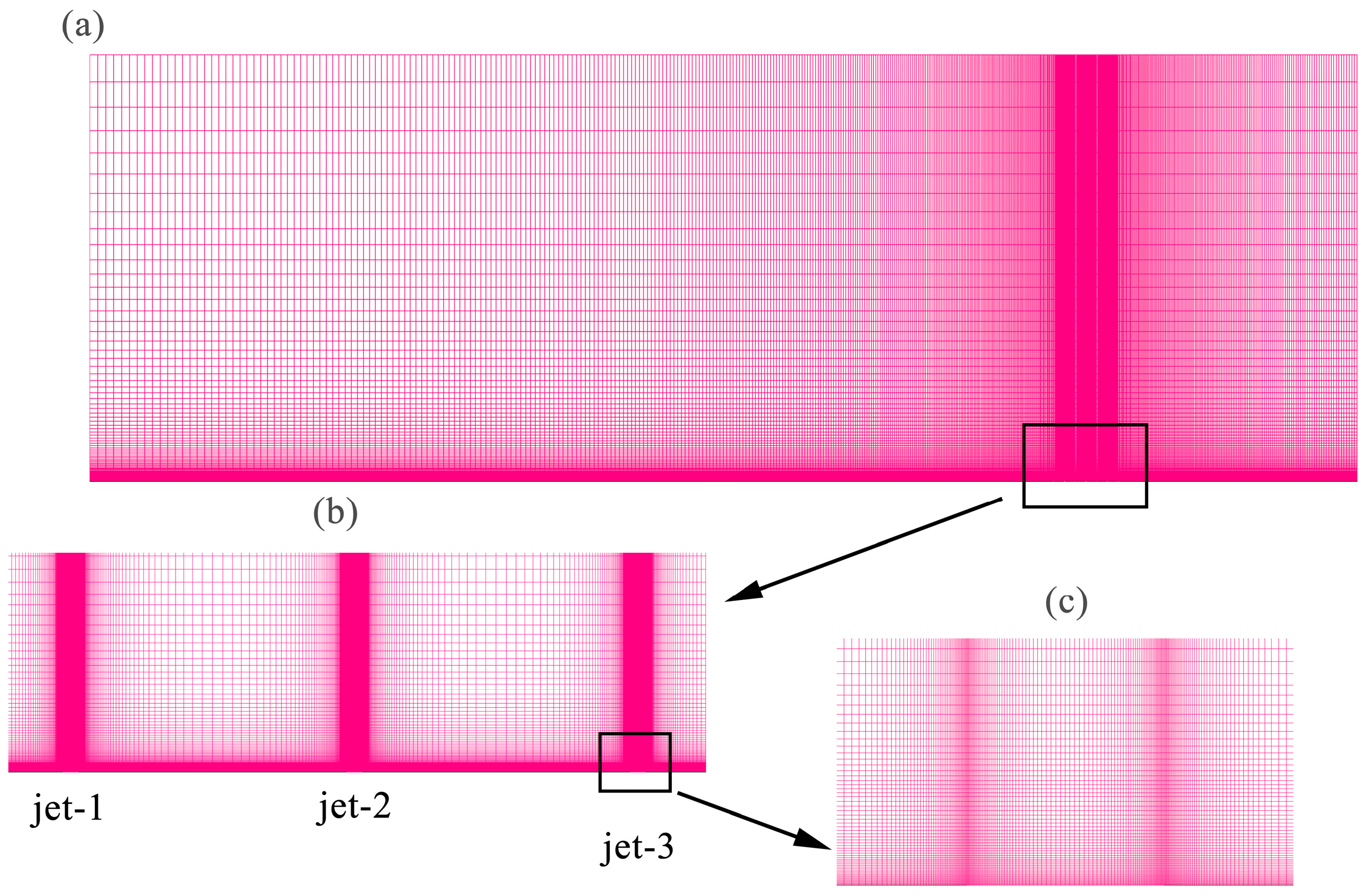
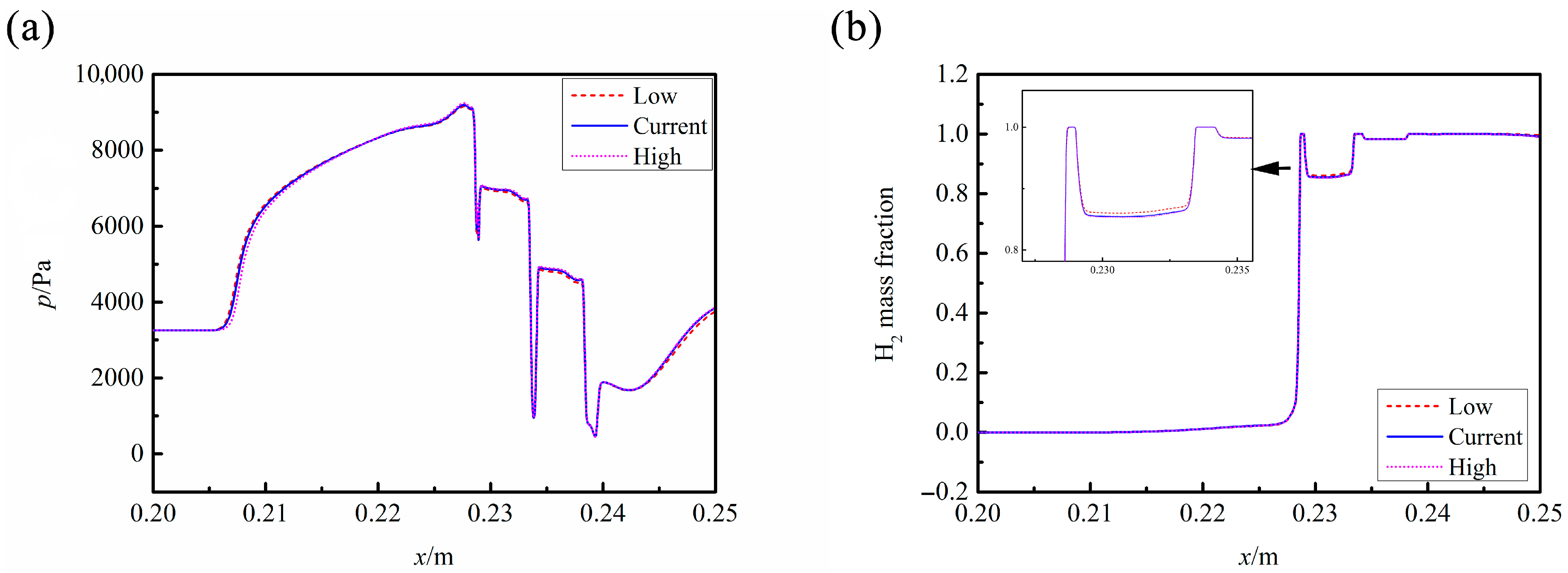
The computational domain is shown in Figure 1. The length of the leading wall, l, is 228.6 mm, and the length of the rear wall, s, is 58.05 mm. The width between two jets is 5 mm. The width of the injector is 0.2667 mm. Structured mesh is utilized to discretize the computational domain, as shown in Figure 2. The first layer of the boundary layer is 0.001 mm, of which the y+ value is smaller than 1. The grid at the injector has been refined, as shown in Figure 2b,c. The grid resolution utilized currently has been grid convergence-tested. Three grid resolutions, 450,000, 240,000, and 130,950, are utilized to simulate the hydrogen injection process. The pressure and H2 mass fraction profiles along the line, which has an offset of 1 mm from the bottom wall, are shown in Figure 3. It can be seen that the difference among the three gird resolutions is negligible. Thus, the middle grid resolution was chosen for the current research. The total pressure for the supersonic inlet flow is 240,078 Pa with a static pressure of 3145 Pa and a total temperature of 298.1 K, which results in a Mach number of 3.5. For the jet-to-crossflow pressure ratio of 8.74, the total pressure for the three jets is 52,043.6 Pa with a static pressure of 27,487.3 Pa. The total temperature of the jets is 357.5 K.

2.3. Validation of the Numerical Methods

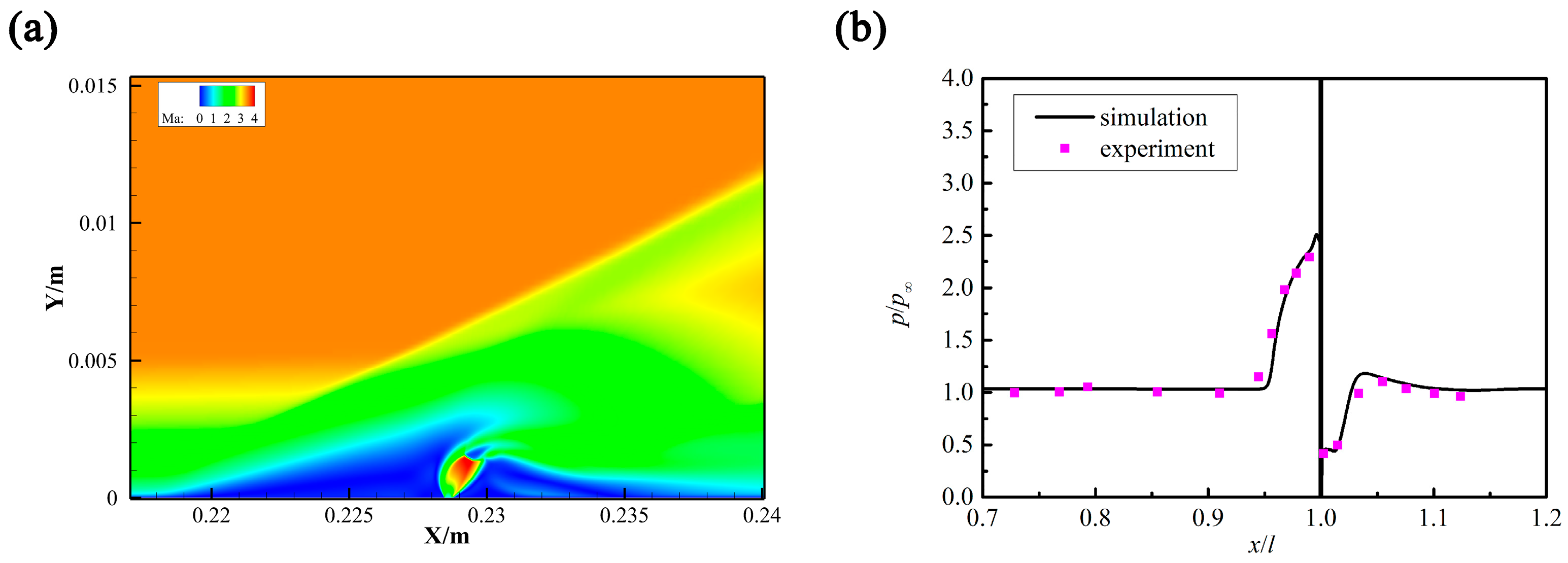
As there is no experiment available for fuel injection in supersonic flow with each injector labeled, the experiment conducted by Spaid [30,31] was taken as a validation for the numerical method used herein. Only one injector is embedded on the wall, and nitrogen is injected from the injector into a supersonic flow. The jet-to-crossflow pressure ratio ( p j / p c ) is 8.74. The Mach number contour and the pressure profiles along the wall surface are shown in Figure 4. It can be seen that this method captures the shock waves and boundary layer separation very well.

3. Results and Discussions

3.1. Flow Fields of the Labeled Jet and the Pure Jet

For a tracing method, two requirements must be fulfilled. Firstly, it cannot affect the flow field, i.e., pressure, temperature, velocity, etc. Secondly, the mass fraction distribution of the hydrogen from each injector must be available. Based on the mass fraction of each ‘hydrogen’, the mixing efficiency and combustion efficiency of each injector can be computed. The focus of the current research is to verify these two features of the tracing method.
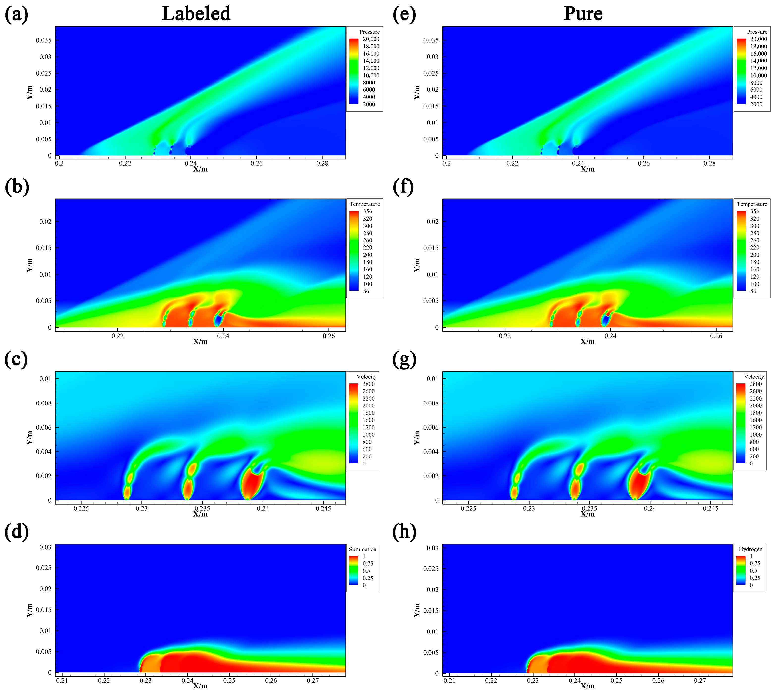
To verify the two features of the tracing method, two cases are simulated: (1) pure injection—the hydrogen from the three injectors is regarded as one species, which is the traditional method; (2) labeled injection—hydrogen is injected from the three injectors, named as Jet-1, Jet-2, and Jet-3. The jet-to-crossflow pressure ratio ( p j / p c ) is 8.74. The three kinds of hydrogen share the same physical and chemical properties. The same boundary conditions are adopted for the two cases. The flow fields of the labeled injection and the pure injection are shown in Figure 5. It can be seen that the pressure, temperature, and velocity distribution are exactly the same. In these figures, the ranges of the levels in the legend are exactly the same. In addition, the mass fraction summation of the three types of hydrogen is shown in Figure 5d. The mass fraction distribution of the summation is the same as that of the hydrogen in the pure injection flow field. Qualitatively, the tracing method has no effect on the flow field. To achieve a quantitative analysis, the profiles along the lines with an offset of 0 mm, 1 mm, and 2 mm from the wall are shown in Figure 6. The legends in the lower box correspond to the Y-axis on the right side. It can be seen that the profiles of pure injection and the labeled injection coincide, as shown in Figure 6a–c. In Figure 6d, the profile of the hydrogen summation of the labeled injection also coincides with the hydrogen profiles of the pure injection. Based on the analysis, it is verified that the tracing method fulfilled the first requirement.

3.2. Effects of the Jet-to-Crossflow Pressure Ratio on the Flow Fields

To further validate the two key features of the tracing method, simulations were conducted with a jet-to-crossflow pressure ratio of 17.12. The comparison of temperature contours between the labeled injection and the pure injection is presented in Figure 7. As shown, the Mach stem of Jet-3 is larger than that observed in Figure 5b,f. This is attributed to the higher jet pressure, which promotes greater jet expansion. Notably, no discernible differences are observed between the temperature contours of the labeled and pure injections. Both flows exhibit boundary layer separation at the same location near 0.195 m.
Temperature profiles along the lines y = 1 mm, 2 mm, and 3 mm, as well as the H2 mass fraction along the outlet, are plotted in Figure 8. The profiles of pure injection and labeled injection coincide perfectly, demonstrating that the tracing method does not influence the flow field.

3.3. Hydrogen Distribution of Each Jet

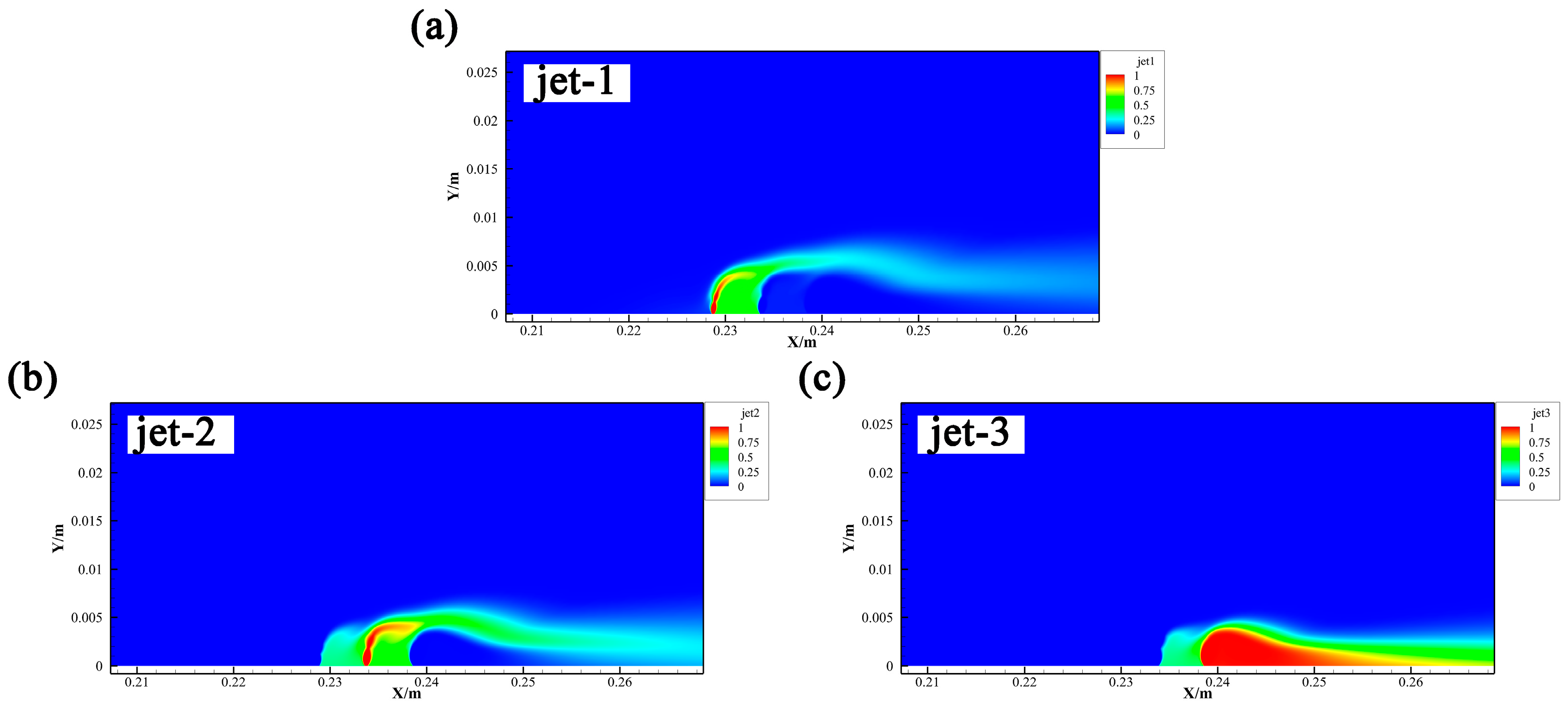
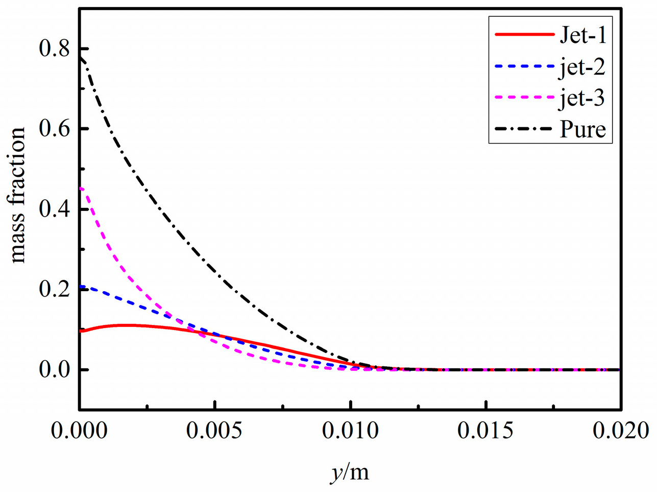
If the hydrogen from one injector does not mix with the air very well, the hydrogen from this injector will be wasted. Hydrogen fuel injection may induce total pressure loss due to the complex shock wave induced by the injection. Thus, the other injectors will pay for the total pressure loss if one injector does not perform very well. To achieve an accurate and efficient design for the hydrogen injection strategy, knowing the mixing efficiency and the combustion efficiency of each injector is necessary. Based on the tracing method, the mass fraction distribution of each injector is available; see Figure 9. The hydrogen mass fraction profiles of the labeled jet and the pure jet are shown in Figure 10. Thus, the mixing efficiency and combustion efficiency of each injector can be computed.
In the current research, the reactions of the species are not considered. When modeling the combustion of Jet-1, Jet-2, and Jet-3, these three hydrogen sources share identical physical and chemical properties, including the pre-exponential factor, temperature exponent, and activation energy. If an elementary reaction mechanism is employed, the intermediate species from each injector are explicitly designated. Specifically, the concentration-dependent terms in the reaction model must be adjusted to represent the summation of contributions from Jet-1, Jet-2, and Jet-3. However, one notable drawback of this tracing method is the significant computational cost incurred due to the requirement of maintaining separate reaction mechanisms for each injector. In addition, the computational cost increases linearly with the number of injectors.

4. Conclusions

A fuel trajectory tracing method is adopted in this research to investigate fuel injection and mixing processes in supersonic/hypersonic propulsion systems. In this research, the hydrogen injected from each injector is designated as a unique species while maintaining identical physical and chemical properties. The nomenclature of these species is distinct for each injector, but they are permitted to interact and mix within the supersonic flow. It is demonstrated that the mass fraction distribution of hydrogen from each injector can be accurately captured without perturbing the flow field. This method enables the calculation of injector-specific mixing and combustion efficiencies, thereby providing a systematic optimization framework for fuel injection strategies in supersonic/hypersonic applications.
In the current investigation, the combustion process within the combustor has not been considered. It is recommended that the combustion model be revised when employing the fuel trajectory tracing method, particularly the terms associated with species concentration. Although the present study is restricted to a two-dimensional framework, the proposed methodology can be extended to three-dimensional configurations due to the preservation of identical physical and chemical properties. The 3D features and the interaction between the species transport and the vortices will be considered in our future research using a direct numerical simulation method.

Author Contributions

Methodology, Q.Q.; Validation, Q.Q. and Y.L.; Investigation, Q.Q.; Resources, Q.Q. and J.L.; Writing—original draft, Q.Q.; Writing—review & editing, Y.Y., Y.L. and M.Y.; Visualization, Y.Y.; Supervision, J.L.; Project administration, J.L. All authors have read and agreed to the published version of the manuscript.

Funding

This project is supported by the National Natural Science Foundation of China (No. 12402431), the Basic Strengthening Program of Science and Technology (2021-JCJQ-JJ-0336), and the Natural Science Foundation of Jiangsu Province (No. BK20220902).

Data Availability Statement

The original contributions presented in this study are included in the article. Further inquiries can be directed to the corresponding authors.

Conflicts of Interest

The authors declare no conflict of interest.

References

  1. Curran, E.T. Scramjet Engines: The First Forty Years. J. Propuls. Power 2001, 17, 1138–1148. [Google Scholar] [CrossRef]
  2. Chang, J.; Zhang, J.; Bao, W.; Yu, D. Research progress on strut-equipped supersonic combustors for scramjet application. Prog. Aerosp. Sci. 2018, 103, 1–30. [Google Scholar] [CrossRef]
  3. Hu, J. Ignition and Flame Stabilization in a Flush Wall Supersonic Combustor. Ph.D. Thesis, Harbin Institute of Technology, Harbin, China, 2013. (In Chinese). [Google Scholar]
  4. Sunami, T.; Scheel, F. Analysis of mixing enhancement using streamwise vortices in a supersonic combustor by application of laser diagnostics. In Proceedings of the AIAA/AAAF 11th International Space Planes and Hypersonic Systems and Technologies Conference, Orleans, France, 29 September–4 October 2002; p. 5203. [Google Scholar]
  5. Tan, Y.; Ni, Y.; Xu, W.; Xie, Y.; Li, L.; Tan, D. Key technologies and development trends of the soft abrasive flow finishing method. J. Zhejiang Univ.-Sci. A (Appl. Phys. Eng.) 2023, 24, 1043–1064. [Google Scholar] [CrossRef]
  6. Ren, Z.; Wang, B.; Xiang, G.; Zhao, D.; Zheng, L. Supersonic spray combustion subject to scramjets: Progress and challenges. Prog. Aerosp. Sci. 2019, 105, 40–59. [Google Scholar] [CrossRef]
  7. Huang, W.; Jin, L.; Yan, L.; Tan, J. Influence of jet-to-crossflow pressure ratio on nonreacting and reacting processes in a scramjet combustor with backward-facing steps. Int. J. Hydrogen Energy 2014, 39, 21242–21250. [Google Scholar] [CrossRef]
  8. Li, L.; Huang, W.; Fang, M.; Shi, Y.; Li, Z.; Peng, A. Investigation on three mixing enhancement strategies in transverse gaseous injection flow fields: A numerical study. Int. J. Heat Mass Transf. 2019, 132, 484–497. [Google Scholar] [CrossRef]
  9. Li, L.; Huang, W.; Yan, L.; Li, S.; Liao, L. Mixing improvement induced by the combination of a micro-ramp with an air porthole in the transverse gaseous injection flow field. Int. J. Heat Mass Transf. 2018, 124, 109–123. [Google Scholar] [CrossRef]
  10. Ma, L.; Yang, P.; Xia, Z.; Duan, Y.; Feng, Y.; Zhao, K.; Xu, L. Experimental study on particle dispersion between particle-laden jet and supersonic crossflow in cavity-structured channel. Chin. J. Aeronaut. 2025, 38, 103320. [Google Scholar] [CrossRef]
  11. Li, J.; Wang, K.; Jiao, G.; Liao, Z.; Li, J. Investigation on low total temperature combustion characteristics of kerosene-fueled supersonic combustor. Chin. J. Aeronaut. 2022, 35, 192–208. [Google Scholar] [CrossRef]
  12. Kim, K.M.; Baek, S.W.; Han, C.Y. Numerical study on supersonic combustion with cavity-based fuel injection. Int. J. Heat Mass Transf. 2004, 47, 271–286. [Google Scholar] [CrossRef]
  13. Moradi, R.; Mahyari, A.; Gerdroodbary, M.B.; Abdollahi, A.; Amini, Y. Shape effect of cavity flameholder on mixing zone of hydrogen jet at supersonic flow. Int. J. Hydrogen Energy 2018, 43, 16364–16372. [Google Scholar] [CrossRef]
  14. Cai, Z.; Sun, M.; Wang, Z.; Bai, X. Effect of cavity geometry on fuel transport and mixing processes in a scramjet combustor. Aerosp. Sci. Technol. 2018, 80, 309–314. [Google Scholar] [CrossRef]
  15. Hassanvand, A.; Gerdroodbary, M.B.; Fallah, K. Effect of dual micro fuel jets on mixing performance of hydrogen in cavity flameholder at supersonic flow. Int. J. Hydrogen Energy 2018, 43, 9829–9837. [Google Scholar] [CrossRef]
  16. Kodera, M.; Sunami, T.; Scheel, F. Numerical study on the supersonic mixing enhancement using streamwise vortices. In Proceedings of the AIAA/AAAF 11th International Space Planes and Hypersonic Systems and Technologies Conference, Orleans, France, 29 September–4 October 2002; p. 5117. [Google Scholar]
  17. Sunami, T.; Murakami, A.; Kudo, K.; Kodera, M.; Nishioka, M. Mixing and combustion control strategies for effecient scramjet operation in wide range of flight Mach numbers. In Proceedings of the AIAA/AAAF 11th International Space Planes and Hypersonic Systems and Technologies Conference, Orleans, France, 29 September–4 October 2002; p. 5116. [Google Scholar]
  18. Choubey, G.; Pandey, K.M. Investigation on the effects of operating variables on the performance of two-strut scramjet combustor. Int. J. Hydrogen Energy 2016, 41, 20753–20770. [Google Scholar] [CrossRef]
  19. Choubey, G.; Pandey, K.M. Effect of parametric variation of strut layout and position on the performance of a typical two-strut based scramjet combustor. Int. J. Hydrogen Energy 2017, 42, 10485–10500. [Google Scholar] [CrossRef]
  20. Choubey, G.; Pandey, K.M. Effect of different strut + wall injection techniques on the performance of two-strut scramjet combustor. Int. J. Hydrogen Energy 2017, 42, 13259–13275. [Google Scholar] [CrossRef]
  21. Génin, F.; Menon, S. Simulation of Turbulent Mixing Behind a Strut Injector in Supersonic Flow. AIAA J. 2010, 48, 526–539. [Google Scholar] [CrossRef]
  22. Gerlinger, P.; Bruggemann, D. Numerical Investigation of Hydrogen Strut Injections into Supersonic Airflows. J. Propuls. Power 2000, 16, 22–28. [Google Scholar] [CrossRef]
  23. Gerlinger, P.; Stoll, P.; Kindler, M.; Schneider, F.; Aigner, M. Numerical investigation of mixing and combustion enhancement in supersonic combustors by strut induced streamwise vorticity. Aerosp. Sci. Technol. 2008, 12, 159–168. [Google Scholar] [CrossRef]
  24. Li, J.; Song, W.; Wand, Y. Experimental study on combustion characteristics of supersonic combustor based on alternating-wedge strut. Chin. J. Aeronaut. 2024, 37, 214–227. [Google Scholar] [CrossRef]
  25. Liu, M.; Sun, M.; Yang, D.; Zhao, G.; Tang, T.; An, B.; Wang, H. Mixing and combustion characteristics in a scramjet combustor with different distances between cavity and backward-facing step. Chin. J. Aeronaut. 2023, 36, 400–411. [Google Scholar] [CrossRef]
  26. Jeong, E.; O’Byrne, S.; Jeung, I.-S.; Houwing, A.F.P. The Effect of Fuel Injection Location on Supersonic Hydrogen Combustion in a Cavity-Based Model Scramjet Combustor. Energies 2020, 13, 193. [Google Scholar] [CrossRef]
  27. Tan, J.; Zhang, D.; Lv, L. A review on enhanced mixing methods in supersonic mixing layer flows. Acta Astronaut. 2018, 152, 310–324. [Google Scholar] [CrossRef]
  28. Liou, M. The evolution of AUSM schemes. Def. Sci. J. 2010, 60, 606–613. [Google Scholar] [CrossRef]
  29. Liou, M. A sequel to AUSM: AUSM+. J. Comput. Phys. 1996, 129, 364–382. [Google Scholar] [CrossRef]
  30. Spaid, F.W. Transverse Slots with Supersonic External Flows. AIAA J. 1968, 6, 205–212. [Google Scholar] [CrossRef]
  31. Sriram, A.T.; Mathew, J. Improved prediction of plane transverse jets in supersonic crossflows. AIAA J. 2006, 44, 405–407. [Google Scholar] [CrossRef]
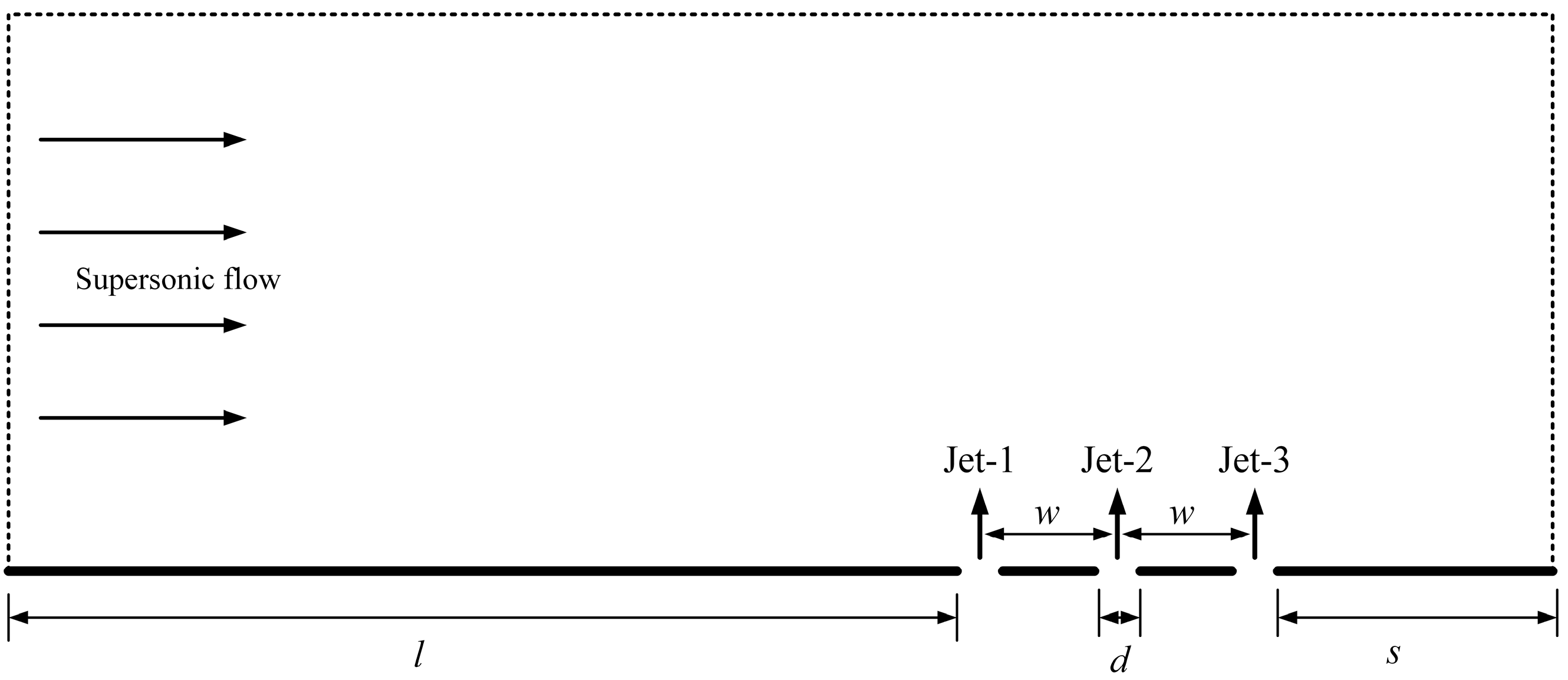
Figure 1. Schematic of the physical model.
Energies 18 04664 g001
Figure 2. Mesh setup with boundary layer. (a) Overall grid; (b) local refinement of fuel injection section; (c) magnified images of the injector.
Energies 18 04664 g002
Figure 3. Pressure and H2 mass fraction profiles. (a) pressure profiles; (b) H2 mass fraction profiles.
Energies 18 04664 g003
Figure 4. Mach number contours and pressure profiles in the validation case. (a) Mach number contours; (b) pressure profiles.
Energies 18 04664 g004
Figure 5. Comparison between the flow fields of labeled injection and pure injection. (a) labeled-pressure contours; (b) labeled-temperature contours; (c) labeled-velocity contours; (d) labeled-mass fraction summation of the three types of hydrogen; (e) pure-pressure contours; (f) pure-temperature contours; (g) pure-velocity contours; (h) pure-H2 mass fraction.
Energies 18 04664 g005
Figure 6. Comparison between the profiles of the labeled injection and the pure injection. (a) pressure; (b) velocity; (c) temperature; (d) H2 mass fraction.
Energies 18 04664 g006
Figure 7. Comparison between the labeled injection flow field and pure injection flow field. (a) labeled-temperature contours; (b) pure-temperature contours.
Energies 18 04664 g007
Figure 8. Comparison between the profiles of the labeled injection and the pure injection. (a) temperature; (b) H2 mass fraction.
Energies 18 04664 g008
Figure 9. Hydrogen mass fraction distribution of the labeled injection. (a) Jet-1; (b) Jet-2; (c) Jet-3.
Energies 18 04664 g009
Figure 10. Mass fraction profiles at the outlet.
Energies 18 04664 g010
Disclaimer/Publisher’s Note: The statements, opinions and data contained in all publications are solely those of the individual author(s) and contributor(s) and not of MDPI and/or the editor(s). MDPI and/or the editor(s) disclaim responsibility for any injury to people or property resulting from any ideas, methods, instructions or products referred to in the content.