Article

Combustion Analysis of the Renewable Fuel HVO and RME with Hydrogen Addition in a Reciprocating Internal Combustion Engine

by
Stanislaw Szwaja
1,*,
Saugirdas Pukalskas
2,
Romualdas Juknelevicius
2 and
Alfredas Rimkus
2
1
Faculty of Mechanical Engineering, Czestochowa University of Technology, Dabrowskiego 69 St., 42-201 Czestochowa, Poland
2
Department of Automobile Engineering, Faculty of Transport Engineering, Vilnius Gediminas Technical University-VILNIUS TECH, Plytinės St. 25, LT-10105 Vilnius, Lithuania
*
Author to whom correspondence should be addressed.
Energies 2025, 18(13), 3381; https://doi.org/10.3390/en18133381
Submission received: 31 May 2025 / Revised: 20 June 2025 / Accepted: 24 June 2025 / Published: 27 June 2025

Abstract

In the era of depletion of fossil fuels, there is an intensive search for renewable fuels for the internal combustion engine, which is the most efficient thermal machine in the power range of several kW to several MW. Hence, this article discusses the results of research on the combustion of renewable fuels such as hydrotreated vegetable oil (HVO) and the rapeseed methyl ester (RME) with the addition of hydrogen, injected in its gaseous form into the intake manifold. The thermodynamic analysis presented in the article discusses progress in the combustion process of these fuels depending on the hydrogen content. The parameters for diesel fuel combustion are given as a reference point. Based on the obtained results, one can conclude that adding hydrogen increases the maximum combustion pressure in the cylinder and significantly accelerates the combustion process in the premixed combustion phase, thus reducing the share of the diffusion combustion phase. This significantly affects exhaust toxic emissions. In connection with this, a shortening of the flame kernels development phase was observed, calculated as the time expressed by the crank angle, to release heat of 10%, and a slight extension of the main combustion phase, managed as the period of the heat released from 10 to 90% was observed as well.

1. Introduction

It is common knowledge that fossil fuels will eventually run out. In addition, fossil fuels are not popular among climate scientists as far as these fuels are blamed for contributions to global warming through CO2 emissions from their combustion. To effectively counteract this, fuels with a neutral carbon balance for the natural environment are sought. In addition, these fuels should be renewable fuels formed by the conversion of unaccumulated (direct) solar energy. In this case, biomass-based fuels deserve attention. Among others, the investigation is focused on two liquids, HVO and RME, which are considered promising fuels for the internal combustion engine [1,2]. Moreover, it has been recognized that co-firing these fuels with hydrogen will lead to an unsustainable reduction in tailpipe CO2 emissions and thus reduce the carbon footprint from means of transport and power generation units [3,4,5]. Hence, hydrotreated vegetable oil (HVO) and rapeseed methyl ester (RME) are the subject of intensive research and there are a huge number of scientific papers dealing with research on these fuels. Among others, several research works are discussed in the following subsections.

1.1. Hydrogen

Hydrogen is a gas often used as an additional fuel mixed with air for an engine powered by liquid fuel, e.g., diesel fuel. Hydrogen is characterized by a high molecular diffusion coefficient, which is considered both an advantage and a disadvantage. In this case, it is an advantage that contributes to better premixing the combustible mixture consisting of air, directly injected liquid fuel, and a small amount of hydrogen. As is known, hydrogen is considered a high-energy resource with a wide range of flammability, low ignition energy, and high diffusivity. Hydrogen is also characterized by a high calorific value, although its energy density is low. During combustion, hydrogen is characterized by a short ignition delay, which improves flame development inside the engine cylinder and thus makes the fuel combustion more similar to the constant-volume process. From the thermodynamic point of view, this contributes to an increase in the thermal efficiency of the internal combustion engine. In addition, a number of research works have confirmed that the use of hydrogen as an additional fuel for the engine helps to reduce CO and unburned hydrocarbon (UHC) exhaust emissions but increases the emission of nitrogen oxides (NOx) compared to working only on a single liquid fuel, e.g., diesel fuel.
As far as hydrogen added as the secondary fuel is concerned, among others, Dimitrov et al. [6] made a quantitative assessment and analysis of the influence of hydrogen on heat release and combustion phases in a single-cylinder CI diesel engine. They recommended that the hydrogen percentage in the total fuel delivered to the engine cylinder should not exceed 35% (by energy) for low engine loads and 15% for nominal loads. The use of hydrogen in CI engines requires careful engine design to avoid abnormal combustion, which is a key issue with high amounts of hydrogen. Rajak et al. [7] investigated hydrogen-enriched diesel and ethanol blends in the CI engine with compression ratios (CR) varying from 15:1 to 19:1. As expected, they observed a decrease in BSFC with hydrogen added. Furthermore, Hosseini and Ahmadi [8] conducted research work on hydrogen–diesel fuel combustion where hydrogen was added at amounts up to 70% (by energy). They observed a reduction in toxic exhaust emissions (CO and UHC). Additionally, they detected combustion knock coming from the combustion of hydrogen added at amounts higher than 54% by energy. One of the interesting works was conducted by Tira et al. [9]. They attempted to improve the combustion characteristics of the CI engine. For this purpose, they used a combustible mixture consisting of a basic fuel (diesel, biodiesel, synthetic diesel), liquified petroleum gas (LPG), H2, and a reformate gas. They found lower smoke, CO, and UHC for biodiesel in comparison to diesel fuel. Unlike hydrogen-assisted diesel fuel, the hydrogen alone is not suitable for self-sustained combustion in CI engines due to its high self-ignition temperature and low cetane number. The combustion of hydrogen can result in significant increases in pressure and temperature, potentially leading to knocking combustion in the engine’s cylinder and increasing NOx emissions due to increase in in-cylinder peak temperature [10].

1.2. HVO and RME

As mentioned, diesel fuel has limited natural resources; therefore, renewable fuels are sought. HVO and RME are fuels worth considering the diesel fuel substitutes. HVO is a hydrotreated biodiesel with a lower density than that of diesel fuel and RME. The HVO fuel is a low aromatic, fully paraffinic, light fraction hydrocarbon, and contains neither sulfur nor oxygen. Unlike HVO, the RME contains considerable oxygen content (10–11%), which results in approximately 12% lower calorific value in comparison to HVO [11]. Usually, RME is referred to as the conventional biodiesel, produced during the esterification of triglycerides with a catalyst (methanol), whereas HVO (commonly known as hydrotreated biodiesel) is the fuel produced during the hydrotreating process of triglycerides. Thus, RME and HVO are different products with different chemical structures and physical properties. Based on the literature review, it was observed that a significant number of research works concern studies of the use of HVO or RME mixtures with diesel fuel for the CI engine. HVO and RME are managed as only additives to diesel fuel. For instance, a different strategy was proposed by Sukjit et al. [12]. They investigated a hydrogen addition to RME-butanol blends and combusted under various EGR ratios to reduce NOx emissions. There are significantly fewer articles discussing the results of the combustion of HVO or RME only. Di Blasio et al. [13] found that in comparison to diesel fuel, HVO significantly reduces regulated engine tailpipe toxic emissions. Similar conclusions on toxic exhaust emissions were obtained by d’Ambrosio et al. [14]. Furthermore, Zaglinskis and Rimkus found lower specific fuel consumption for the engine-fueled HVO [11]. Liu et al. [15] conducted an investigation on applying EGR in the HVO-fueled engine and they found promising results on specific fuel consumption and NOx exhaust emissions. Cheng et al. [1] investigated HVO, RME, and diesel fuel in the optically accessible CI engine. The results from their study confirmed that the ignition delay of HVO and RME occurs earlier, and the flame propagation at the premixed combustion stage proceeds faster compared to diesel fuel. A comparison of the HVO and RME shows that there is a marginal difference in the ignition delay for these two fuels. Hunicz et al. [16] conducted research on RME and HVO and they found that lower injection pressures are required in comparison to diesel fuel. Furthermore, they also confirmed a reduction in all toxic emissions compared to diesel fuel. Happonen et al. [17] used a mixture of di-n-pentyl ether and HVO to reduce particulate matter (PM), but the NOx emission was marginally increased or decreased depending on the engine load. Wu et al. [18] performed a comparative analysis of HVO and diesel fuel combusted in a typical diesel engine. They suggested that HVO has high potential to reduce diesel engines’ carbon footprint and exhaust PM emissions. The advantage of HVO as a valuable engine fuel with low exhaust emissions was also confirmed by Aatola et al. [19]. They observed a decrease in both UHC, CO, and NOx emissions, and also lower specific fuel consumption in comparison to a diesel-fueled engine. As summarized in the field of exhaust toxic emissions, Orlinski et al. [20] stated that HVO fuel can replace diesel fuel in compression-ignition engines even without any significant modifications in the engine construction and settings.
As a result of the literature review, one can draw a conclusion that the available literature focuses mainly on toxic exhaust emissions. Unfortunately, the database of articles presenting a comparative analysis of the combustion of diesel fuel, HVO, and RME is relatively poor in comparison with the number of studies on toxic emissions from the engine. Furthermore, there is a gap in the scientific literature concerning the comparative analysis of these hydrogen-added fuels, although there are several works addressing this topic.
One of the works focused on hydrogen and HVO was conducted by Pinto et al. [21]. They tested a hydrogen addition of 7.3%, 17.5%, and 28% (by energy) to HVO-diesel fuel and observed reductions in PM, CO, and CO2 emissions. However, an increase in NOx was observed. Pinto and his group [21,22] also investigated HVO and farnesane with the addition of hydrogen, biogas, and natural gas in dual-fuel CI engine operation. They observed longer ignition delay, but decreased combustion duration. Pechout et al. [23] conducted research on maximum heat release rate for HVO- and FAME-fueled engines and made a comparison with a diesel engine. They stated that maximum combustion rates were comparable for diesel and FAME but were advanced when working on HVO. They also suggested optimization of fuel injection timings for the HVO-fueled engine. During co-combustion of RME with hydrogen, as stated by Tutak et al. [5], a milder combustion process was observed, characterized by smaller increments in pressure and heat release rate compared to the combustion of sole diesel fuel. Both hydrogen–diesel and hydrogen–RME combinations resulted in the CA50 angle approaching closer to TDC with an increase in the hydrogen fraction in the entire air–fuel mixture. The study conducted by Lionus Leo et al. [24] focused on the optimization of a dual-fuel CI engine powered by cashew nut shell oil (CNSO) biodiesel and hydrogen with the use of response surface methodology (RSM). Investigations were performed with the use of CNSO biodiesel and CNSO biodiesel–diesel fuel blend without and with a supply of H2 at flow rates of 3 dm3/min and 6 dm3/min at engine loads from minimum to full-load of 100%. The optimal fuel mixture setup was identified through RSM at a 50/50% CNSO biodiesel–diesel blend with a 6 dm3/min H2 flow rate under 80% engine load. Rimkus and Juknelevicius [25] found that the combustion of the rich RME fuel mixture with hydrogen addition up to 44% by energy in the CI engine becomes intensified at the beginning of the combustion process and shortens the ignition delay phase denoted as CA0-02.
Based on the literature survey, one can conclude that there is a gap in the field of interest. Thus, the research presented in this article is fully justified and at least partially fills this knowledge gap. The research discussed in this article is the fundamental research aimed at answering the question of how beneficial it is to co-combust hydrogen with a renewable fuel of plant origin (HVO or RME) in the reciprocating internal combustion engine. A reliable answer can be given as a result of conducting a comparative analysis, where the reference fuel is commonly used diesel fuel.

1.3. Combustion Analysis

To investigate the combustion process in the cylinder of a reciprocating internal combustion engine, proven research methods are used, which involve analysis of the course of heat release, calculation of the initial CA0–10 and main combustion CA10–90 phases, and determination of the premixed and diffusion combustion phases. These methods are based on in-cylinder pressure data processing with the aid of the energy conservation law. As found, they are reliable and effective tools for combustion analysis. Hence, they are commonly used by researchers worldwide [26,27,28,29]. Furthermore, the second law of thermodynamics with exergy analysis is also successfully implemented into engine combustion analysis [30,31,32]. Thus, this methodology approach is applied in this article as this is in line with the trends in engine thermodynamics.

2. Materials and Methods

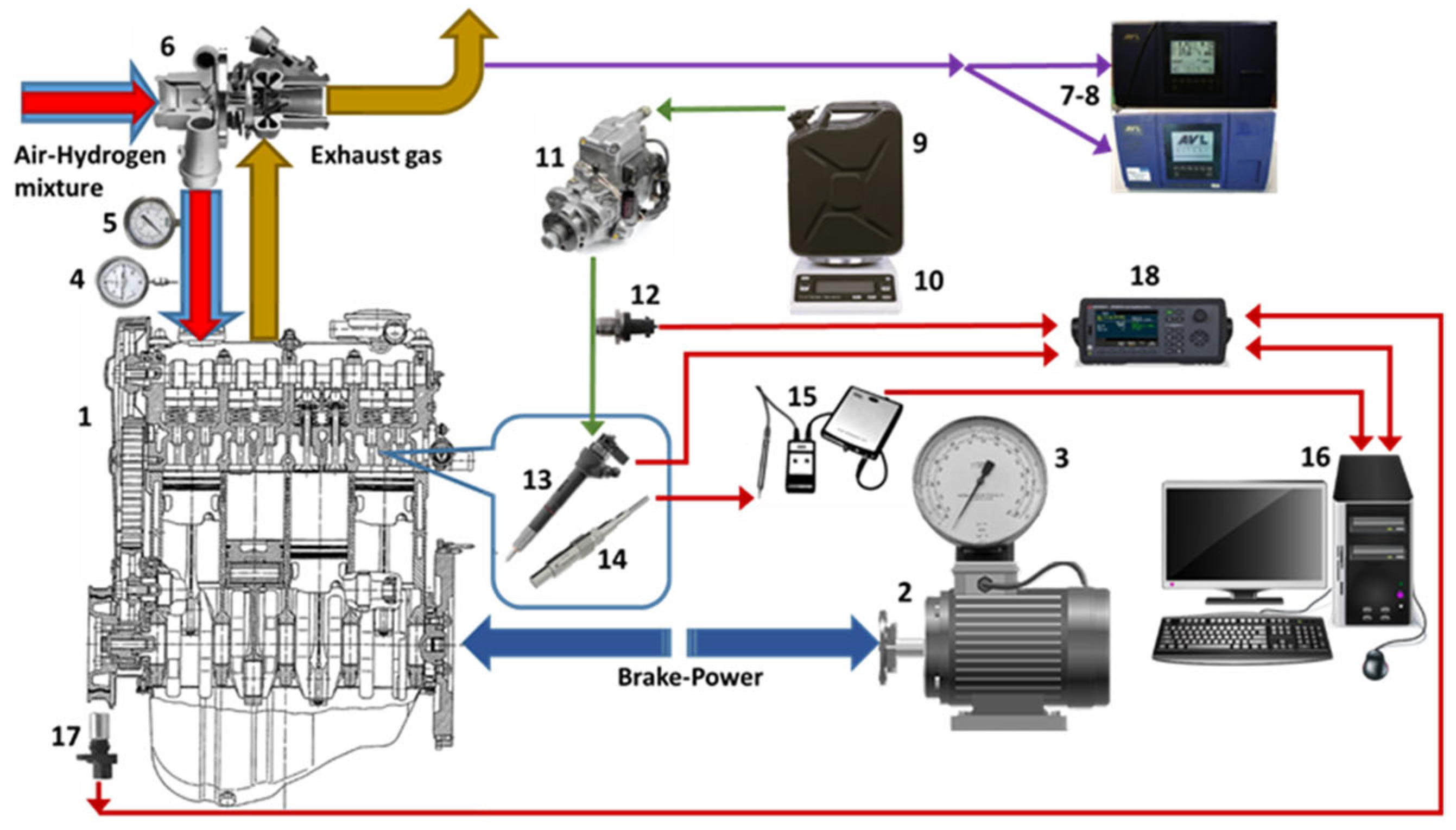
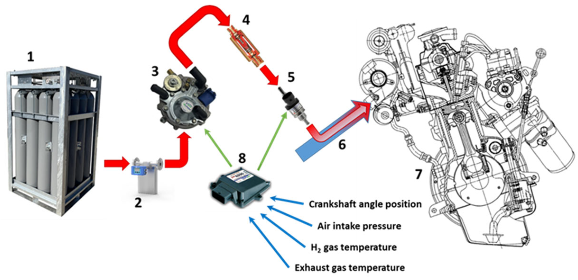
2.1. Experimental Setup
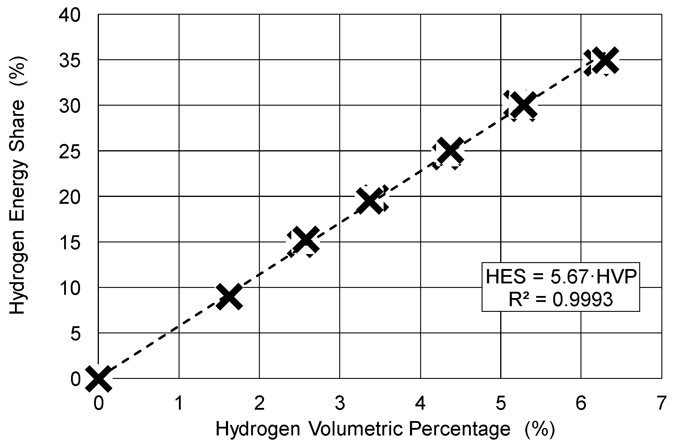
Experiments were performed at the Laboratory of Transport Engineering of Vilnius Gediminas Technical University. The Audi/VW TDI compression-ignition (CI) diesel engine (Volkswagen AG, Wolfsburg, Germany) with a turbocharger, electronically controlled BOSCH VP37 fuel pump, and conventional mechanical fuel injection system were used for tests. The diagram of the test bed is shown in Figure 1. The engine was modified to work on hydrogen, which was injected into the intake port just before a turbocharger.
Detailed technical engine specifications are provided in Table 1.
Details of the line for hydrogen delivering to the engine are shown in Figure 2.
Hydrogen was supplied out of the high-pressure tanks to the Coriolis-type mass flow meter RHEONIK RHM 015 (Rheonik Messtechnik GmbH, Odelzhausen, Germany), which was connected to the fuel supply system mounted before the gas pressure-reducing valve. The data of the gas pressure-reducing valve and the gas flow control unit are provided in Table 2 and Table 3, respectively.

2.2. Methodology

The research methodology applied in this article is based on the comparative analysis of the combustion process of the fuel directly injected into the engine cylinder: RME or HVO and hydrogen injected into the intake manifold and premixed with air sucked by the engine. The reference fuel is the regular light diesel fuel. The thermodynamic analysis refers to the in-cylinder combustion process. Thus, it does not include either analysis during the compression or the expansion stroke. In-cylinder pressure was used as the input data to determine the following quantities with the aid of the energy conservation law:
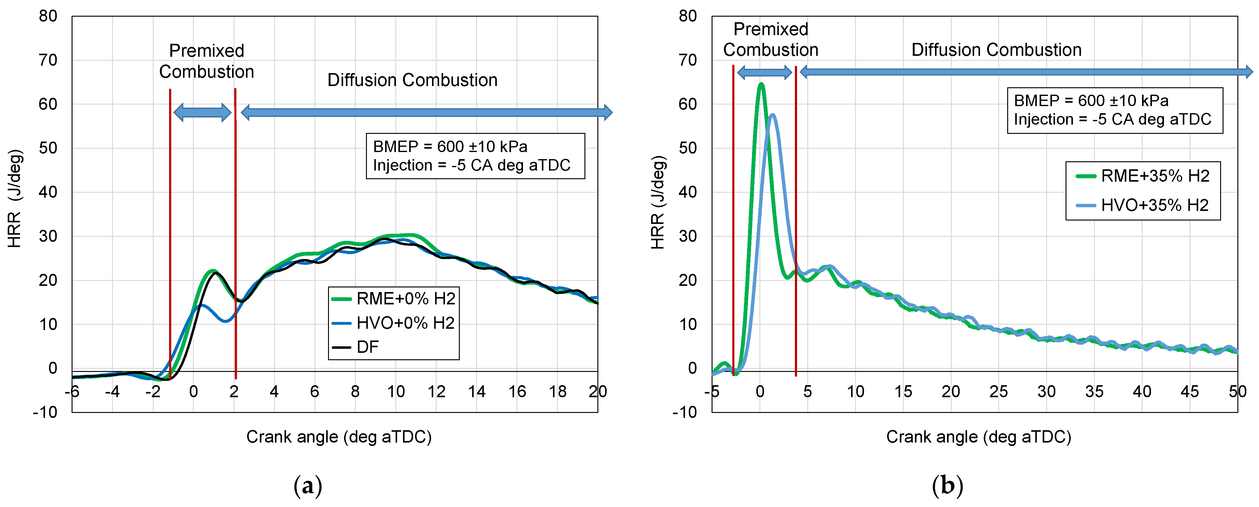
  • Heat release rate (HRR) divided into premixed and diffusion combustion phases;
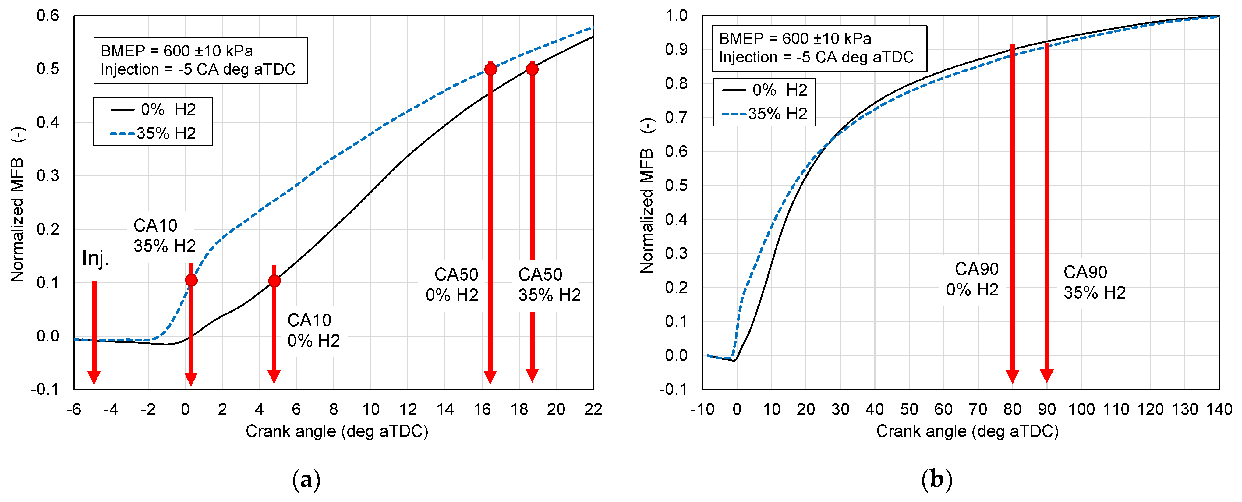
  • The course of burning out the fuel, denoted mass fraction burnt (MFB), including the initial phase CA0–10, which is affected by the fuel self-ignition delay, and the main combustion phase denoted CA10–90.
As far as HRR is analyzed, one should pay attention to its calculation. For this purpose, HRR is calculated on the basis of net heat released during combustion. Thus, this approach simplifies the final and world-wide well-known formula for HRR defined in Equation (1),
dQnet/d(CA) = κ/(κ − 1)·p(CA)·dV(CA)/d(CA) + 1/(κ − 1)·V(CA)·dp(CA)/d(CA),
where Qnet is the heat released from entire fuel combustion decreased by heat transferred to a cooling system and other heat losses, mainly resulting from unburnt fuel coming from blow-by and crevices effects; κ is the specific heat ratio for gases filling the engine cylinder; p is in-cylinder pressure; and V is real volume of the cylinder space at a specific crank angle CA.
This study was conducted to analyze the effect of hydrogen-assisted combustion of HVO and RME. Regular diesel fuel was used as the reference fuel to find out any differences in the combustion process of sole RME and HVO.
During the test series, engine speed, injection angle, and brake mean effective pressure (BMEP) were maintained fixed. The tests were carried out under the following regimes as presented in Table 4.
The CI engine was connected to a dynamometer, KI–5543 (Gosniti Rosselhozakademii, Moscow, Russia) to manage and monitor the engine speed a nd load. The engine was set to operate at a speed of 2000 rpm. Each experiment was performed at fixed loads of 30 Nm (corresponding to BMEP = 0.2 MPa), 60 Nm (BMEP = 0.4 MPa), and 90 Nm (BMEP = 0.6 MPa). The engine loads were controlled through varying the liquid fuel flow rate.
Raw in-cylinder pressure courses from individual combustion events were filtered with a low-pass Butterworth filter of the 4th order with a cut-off frequency of 3.5 kHz. Finally, the in-cylinder pressure from each test series was calculated as the mean pressure over the set of 75 individual consecutive combustion events from this test series. Thus, parameters that were considered fixed were determined as mean values characterizing a specific test series. The amount of hydrogen added to the basic fuel was changed from 0 to approximately 7% by volume, and then this hydrogen volumetric percentage (HVP) was converted to the hydrogen energy share (HES), referring to the total energy in the entire fuel dose, consisting of both basic fuel and hydrogen.
As one can expect, the correlation between HES vs. HVP is a typical analytical one, as depicted in Figure 3.

Characteristics of Fuels Used for Investigation

The hydrogen used for tests was a technical hydrogen with a purity of 99.999%.
The reference fuel was the regular light diesel fuel (DF) fulfilling the requirements of LST EN590:2009+A1 [33] produced by ORLEN Lietuva Ltd (Mažeikiai, Lithuania).
HVO meets EN 15940:2016 [34] requirements for paraffinic diesel fuel. The common RME specification is prescribed by the EN 14214:2008 [35].
HVO is a hydrocarbon paraffin fraction obtained as a result of the catalytic hydro-conversion process of triglycerides of fatty acids. HVO is characterized by better chemical stability and low hygroscopicity compared to typical biofuels as RME is among others. In terms of physicochemical properties, HVO has no oxygen, has a self-ignition temperature similar to diesel fuel between 70 and 80 °C, while for RME it is over 150 °C. HVO has about 30% higher kinematic viscosity vs. diesel fuel, which makes spraying and breakup into drops, as well as atomization and evaporation, more difficult. However, the standard requirements set the viscosity from 2 to 4.5 mm2/s for diesel fuel. HVO has worse lubricating properties than diesel fuel. In the case of using HVO, a lubricant additive may be necessary to improve the lubricity of this fuel and maintain the durability of the high-pressure injection system. A higher cetane number in relation to both diesel fuel and RME makes it easier for HVO to ignite. Hence, a shorter ignition delay is expected in this case.
Detailed specifications of the fuels used in tests are given in Table 5.

2.3. Uncertainty Analysis

Data and measurement accuracy of the main measurement devices are provided in Table 6.
The peak combustion pressure, combustion phases CA0–10 and CA10–90, and the maximum in HRR were calculated as the mean values from the populations of 75 combustion events from each test series. Uncertainties of these quantities were calculated as the standard deviations for these populations and are given in Table 7.

3. Results and Discussion

The research results are presented in three sections describing raw in-cylinder pressures, HRR, and MFB and the values resulting from them as follows:
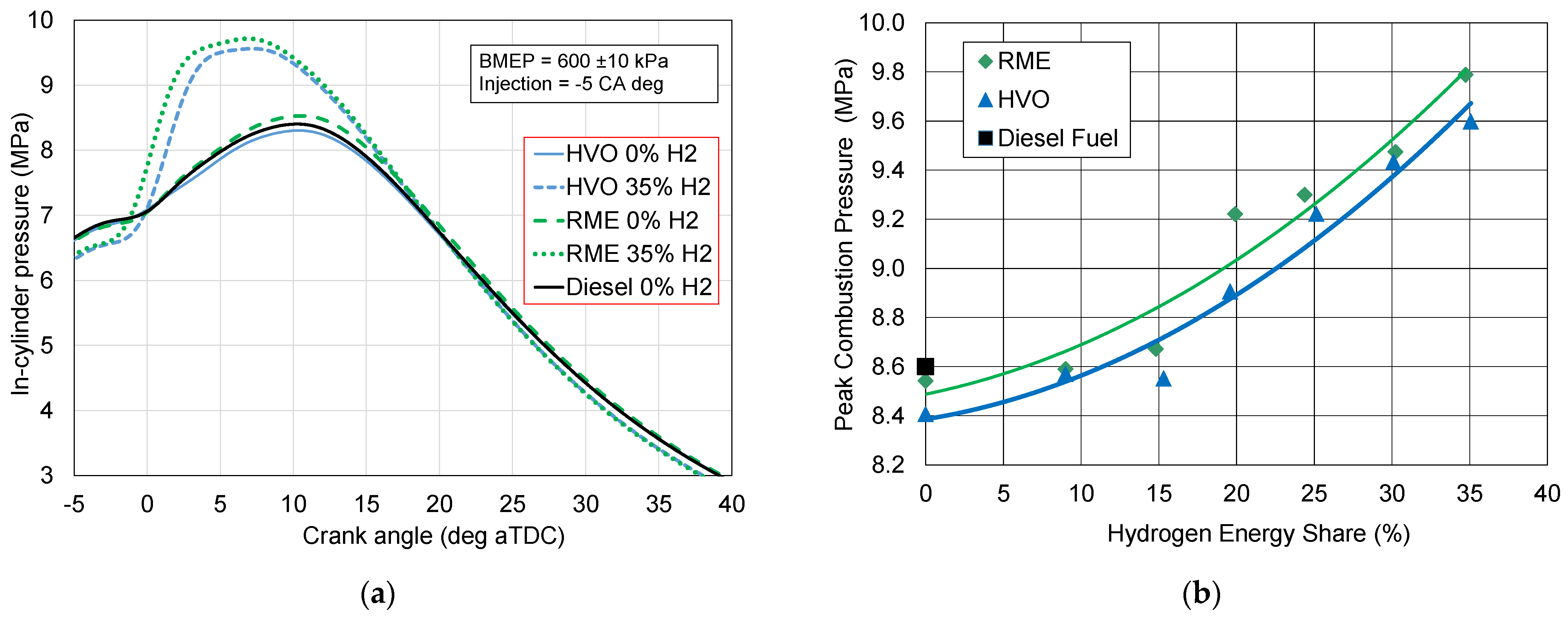
  • Peak in-cylinder combustion pressure;
  • Premixed combustion phase;
  • Diffusion combustion phase;
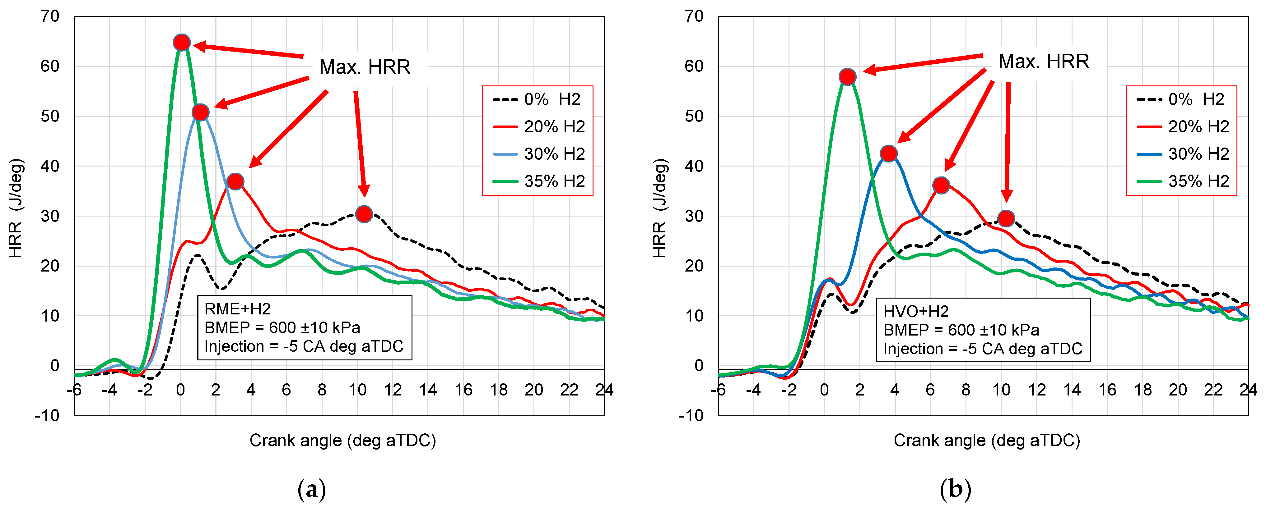
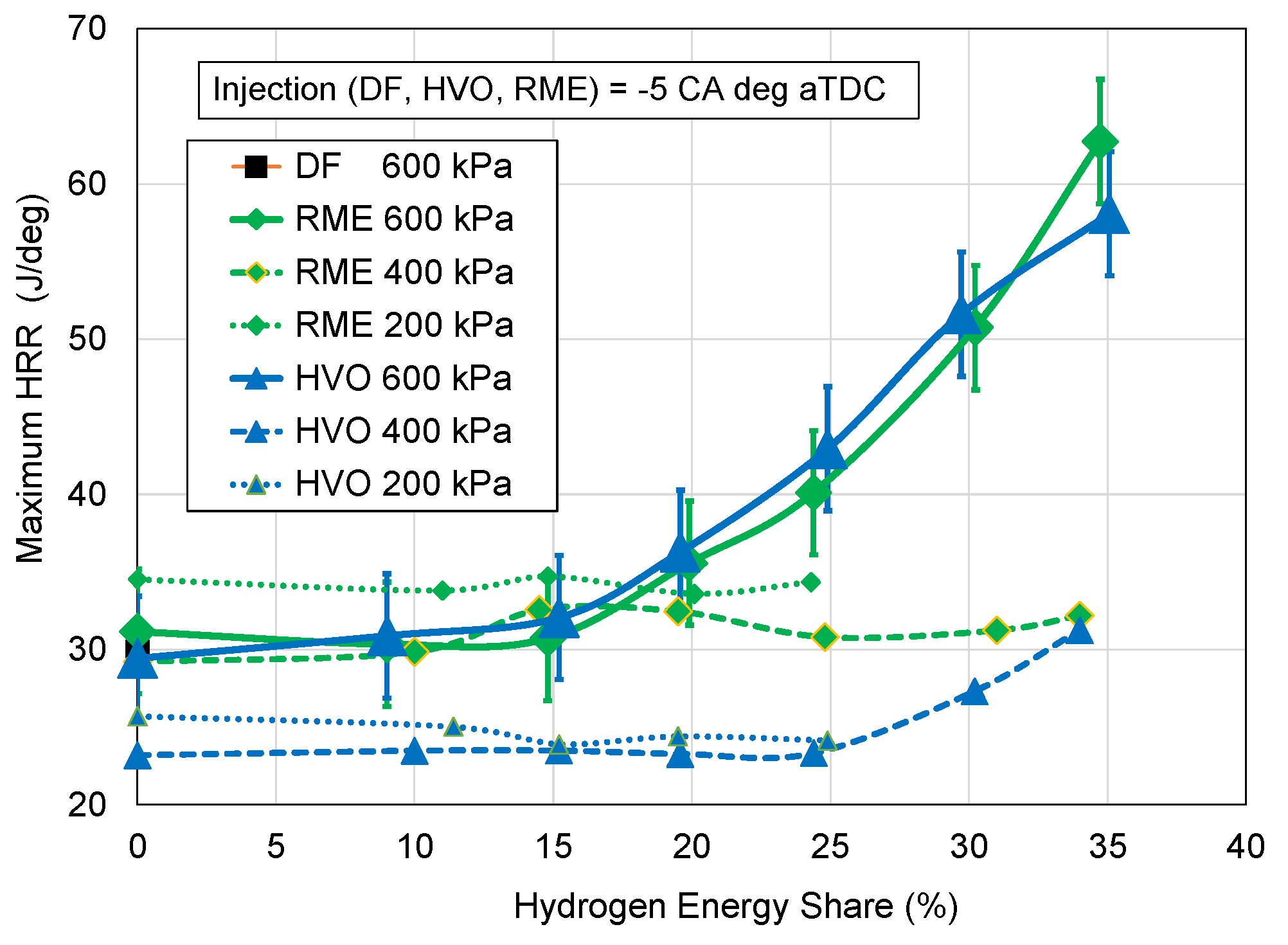
  • Maximum HRR;
  • First combustion phase denoted CA0–10;
  • Main combustion phase CA10–90;
  • Entire combustion duration CA0–90.

3.1. In-Cylinder Combustion Pressure

Figure 4a shows exemplary pressure curves in the range covering fuel combustion: sole DF, sole HVO, sole RME, and HVO and RME with a maximum amount of hydrogen added at 35% by energy content. As observed, after adding hydrogen, the pressure sharply increases just after ignition located at −5 crank angle deg. It can be concluded that this rapid increase in combustion pressure results exclusively from hydrogen combustion. As depicted in Figure 4b, the increase in the peak combustion pressure with the increase in hydrogen injection doses is confirmed. The engine was loaded to BMEP = 600 kPa, and all tests were carried out for this constant load in this case, so the total amount of energy in the fuels (liquid fuel and H2) was maintained at a constant. Therefore, it is no surprise that the final pressure before ignition during the compression stroke for the basic liquid fuel and hydrogen mixture is slightly lower than the pressure for the liquid fuel without H2. This is due to the presence of hydrogen and the need to reduce the amount of liquid fuel dose and thus reduce the amount of air necessary for the combustion of this liquid fuel with hydrogen.

3.2. Heat Release Rate

On the basis of the in-cylinder pressure, the heat release rate was determined. Figure 5a shows HRR for tests of the only liquid fuels (RME, HVO, and DF) combusted. As one can notice, the HRR curves for RME and HVO compared to diesel fuel look almost identical, which confirms the conclusion repeatedly noted in many of the research works on high similarities in combustion of HVO and RME to diesel fuel. However, after adding hydrogen, the HRR changes dramatically (Figure 5b). Diesel fuel with hydrogen was not tested, because diesel fuel was to serve as a reference fuel in its pure form as a fossil fuel. On the other hand, HVO and RME with hydrogen are fully renewable fuels. As mentioned in the previous section, the increase in the in-cylinder pressure (Figure 4) is caused by hydrogen added to the combustion process. Based on HRR courses, one can find a significant difference while comparing Figure 5a with Figure 5b. Premixed combustion is the combustion of fuels in their gaseous forms after they have been perfectly premixed with an oxidizer, in this case, air. Diffusion combustion is combustion that occurs at a space where both air and a fuel have not been mixed. This type of combustion also occurs on the surfaces of liquid fuel droplets. Plenty of studies have shown that premixed combustion goes at a remarkably higher rate than diffusion combustion. Both types of combustion occur in a compression ignition engine, where liquid fuel is injected into the cylinder. Part of this fuel evaporates, mixes with air, and burns as premixed combustion. Droplets that have not completely evaporated burn more slowly. On the HRR diagram, one can try to separate the premixed combustion phase from the diffusion one, but it is difficult. It should be noted that both combustion phases occur simultaneously in a certain time interval. However, combustion in a CI engine proceeds according to the scheme that in the initial stage, there is premixed combustion, and in the final stage, diffusion combustion plays a leading role. In this case (Figure 4a), it was assumed that the negative slope in this first phase of combustion, marked as premixed combustion, indicates a slowdown in combustion, and then, after reaching a minimum, combustion accelerates again, but this is diffusion combustion. Comparing the HRR graphs from Figure 5a,b, one can see a clear increase in the burning rate resulting from the addition of hydrogen to the combustible mixture. However, what is noteworthy is the location of the HRR maximum, which practically remains in the same place, whereas the time of the negative slope is extending. It can be explained by the increased temperature and faster evaporation of liquid fuel droplets with hydrogen addition, which in turn maintains a relatively high burning rate of the liquid fuel. Both HVO and RME with hydrogen causes the same effect; however, HVO combustion is slightly slower (Figure 5b).
As part of the research, tests were performed for three selected engine loads expressed by BMEP of 200, 400, and 600 kPa and a hydrogen addition of 35% as depicted in Figure 6a,b. As can be seen in Figure 6a (RME) and Figure 6b (HVO), the maximum combustion rate increases with increasing engine load, particularly when hydrogen amounts are the highest of 35% by energy. Furthermore, it can be seen that the increase in engine load, in fact, the increase in the amount of liquid fuel and hydrogen, contributes to the earlier occurrence of the HRR maximum.
The previously presented conclusion regarding the acceleration of the combustion process, drawn from the graphs in Figure 4, Figure 5 and Figure 6, can be easily confirmed by observing the HRR courses for several different doses of hydrogen added to the engine cylinder (Figure 7). The maximum of HRR increases with the increase in the amount of added hydrogen. Moreover, the location of the maximum of HRR occurs earlier with the increase in hydrogen injected. This trend is confirmed for both the RME + H2 and HVO + H2 fuels (Figure 7a,b).
Figure 8 presents the correlation between HRR maximum and hydrogen content under various engine loads expressed by BMEP from 200 to 600 kPa. It fully illustrates the upward trend in the maximum combustion rate under a maximum BMEP of 600 kPa. Figure 8 shows a clear upward trend in these heat release rates for hydrogen contents above 20% by energy. For the BMEP of 200 and 400 kPa, the trend is undefined. It is difficult to conclude the nature of the trend in this case, especially since the deviations of all maximum HRR values are within the measurement uncertainty limits. Uncertainties for lower BMEPs were not included to make the graphs more readable. They were of the same order as uncertainties for tests at 600 kPa BMEP (Table 7). One can conclude that for lower engine loads (i.e., lower doses of liquid fuel + H2), there is no significant change in maximum HRR depending on the hydrogen content in such a combustible mixture. The only variable factor in this case is the real equivalence ratio, which increases with decreasing load, which is typical for a CI engine fueled with diesel fuel, as is HVO and RME in this investigation. Thus, further analysis deals with the load of 600 kPa.

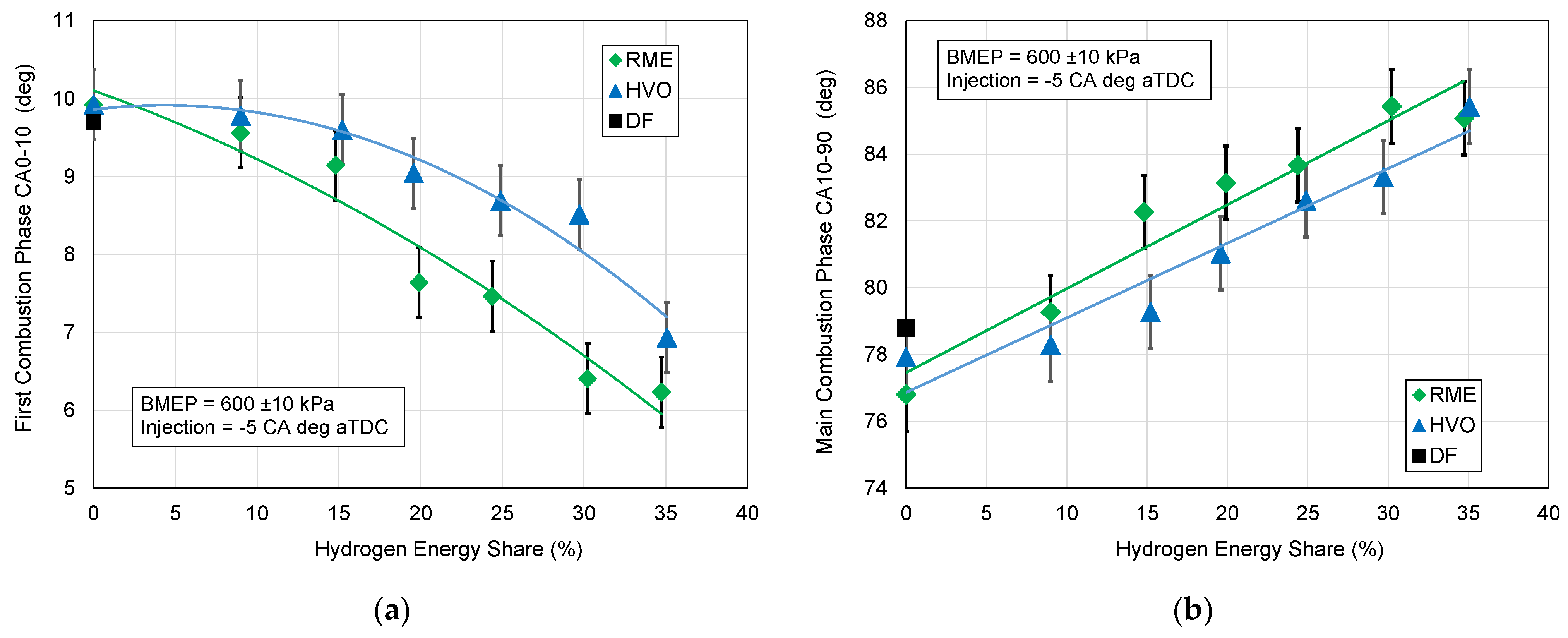
3.3. Combustion Phases

This section discusses the progress of combustion expressed by normalized mass fraction burnt (MFB) using the two following phases:
  • The first combustion phase CA0–10, counted from the injection of liquid fuel to 10% heat released;
  • The main combustion phase CA10–90, counted from 10 to 90% of heat released.
The analysis of MFB was carried out for the engine working at the highest load with BMEP equal to 600 kPa. Figure 9a shows the method of determining the characteristic points CA10 and the combustion center CA50 for the pure RME fuel and RME with the maximum hydrogen addition of 35%. Figure 9b presents the location of CA90. RME is given here as an example. Detailed results for both RME and HVO fuels are given in Figure 10a,b.
An important conclusion from the graphs in Figure 9 can be drawn about the length of the combustion phases CA0–10 and CA10–90. It can be easily noticed that the CA10 location for the liquid fuel (RME in this case) with hydrogen of 35% occurs earlier than that for liquid fuel alone. CA0–10 is often identified with the ignition delay, which has a decisive impact on the further course of combustion. This is not surprising, as it has already been found that adding hydrogen speeds up the combustion process, especially in the premixed combustion phase. However, the center of combustion denoted CA50 (meaning 50% fuel burnt) for liquid fuel (RME or HVO) with hydrogen occurs later than that for liquid fuel alone. The same observation concerns the point CA90. This statement may only seem untrue at first glance. After a deeper analysis, it can be concluded that this is a regularity that is typical for the CI engine. The shorter the first combustion phase, the longer the main combustion phase. Hydrogen can strengthen this effect, because it burns much faster than the parallel burning liquid fuel. In this way, hydrogen consumes oxygen and produces water (in fact steam at combustion conditions), which is a substance somewhat inert to combustion. Therefore, the remaining oxygen is diluted, which causes a decrease in the rate of the chemical reaction of combustion following the Arrhenius law.
The results shown in the graphs in Figure 10a,b summarize these considerations. The first combustion phase, CA0–10, is shortened with the increase in the hydrogen dose. This shortening is very distinct because in the case of the highest hydrogen dose (35%), CA0–10 is shortened by approximately 30%. However, the main combustion phase CA10–90 (Figure 10b) is prolonged with the increase in a hydrogen dose, which confirms the previously put forward thesis that shortening CA0–10 causes prolongation of CA10–90.
When comparing RME and HVO fuels, the same correlation can be observed. HVO has a longer CA0–10 phase and a slightly shorter CA10–90 phase compared to HVO fuel.
Finally, to close the discussion on combustion phases, results on the overall combustion duration are welcome. It is widely known that it is difficult to estimate the end of combustion (the CA100 point), because it is burdened with a large measurement uncertainty. Therefore, it was assumed that the CA0–90 would be more adequate for assessment and would make a more reliable correlation with the amount of hydrogen injected into the engine. As shown in Figure 11, CA0–90 slightly increases with increasing hydrogen content. This increase relative to the reference point (0% H2) does not exceed 6% for both of these fuels. This can be explained by oxygen dilution with progress in combustion, as was performed for the CA10–90 phase.

3.4. Discussion Summary

In summary of this discussion on the analysis of the combustion process using HRR and MFB, it can be stated that it is a reliable tool for assessing the combustion process, and therefore, so is a valuable and useful tool. However, the question remains, what application conclusions can be drawn from the results of the HRR and MFB analysis, and how this translates into the assessment of the quality or suitability for use of the fuels tested. In this case, there is no simple and unambiguous answer. On the one hand, the combustion process should be as short as possible to make the real p-v diagram closer to the diagram for the theoretical Otto thermodynamic cycle, which is characterized by the highest thermodynamic efficiency. On the other hand, too fast a combustion process in the first phase causes a delay in the second main combustion phase, so it might adversely affect the emission of toxic compounds and soot and increase the average temperature of exhaust gases.
The discussion is extended with the hydrogen impact on the combustion process. However, it should be noted that in this case, hydrogen is not only a gas that burns on its own, but it can affect the pre-flame reactions for liquid fuel (HVO or RME), being a precursor (as an extremely active radical) and causing a shortening of the self-ignition delay of the liquid fuel. Therefore, the co-combustion of hydrogen with liquid fuels should be considered in two cases as follows: below the lower flammability limits (LFL) of hydrogen and above LFL. It can be assumed that a small amount of hydrogen below LFL does not directly participate in combustion but only works as a source for forming radicals H+, which should contribute to shortening the self-ignition delay of the liquid fuel. However, if hydrogen occurs above the LFL, then it is ignited by a flame from the self-ignition of the liquid fuel, which seems to be a very likely phenomenon. Hence, one can conclude that with increasing hydrogen content, the 0–10 phase shortens while the main 10–90 phase lengthens. As for the oxygen concentration inside the engine cylinder, it plays a key role in the combustion rate and in both the CA0–10 and CA10–90 combustion phases. The role of the oxygen concentration is particularly noticeable during the main combustion phase CA10–90, where its percentage decreases with combustion progress. As is known, hydrogen burns much faster than the liquid fuels, even when they are premixed as vapors in air. Hence, oxygen percentage in the gas phase is not only reduced but also is diluted in higher amounts of exhaust gases, partially formed from hydrogen combustion at the premixed phase. As is known, the chemical reaction rate is in line with reactant concentrations following the Arrhenius equation. Such hypotheses are not without sense; however, the theoretical background in this case has not been completely developed. From these analyses, one can conclude that the influence of hydrogen on the shortening of the self-ignition delay is significant, but only when hydrogen as the reagent is in the form of radical H+. When it is present as H2, then its influence is unnoticeable, and even opposite to the expected one. Thus, this can be an explanation for the prolonged combustion in the CA10–90 phase. Summing up, CA10–90 becomes longer due to a decrease in the chemical reaction rate caused by dilution of both liquid fuel vapors and oxygen in exhaust gases, additionally formed from hydrogen combustion. These trends in CA0–10 and CA10–90 are confirmed.
Studies have shown that there are no significant differences in the combustion progress of HVO and RME compared to pure DF. However, with increasing H2 content, the CA0–10 phase time is shortened. However, the total combustion time changes slightly. It can be concluded that to obtain maximum BMEP, it is necessary to correct the start of liquid fuel injection. The results of the heat release analysis should mainly provide information on potential modifications to the injection system and engine operating parameters (equivalence ratio, engine speed, load, boosting pressure, fuel direct injection pressure, etc.).

4. Conclusions

Based on the research conducted, the following conclusions can be drawn:
  • Regular diesel fuel, RME, and HVO as the only fuels burn at nearly the same combustion rates;
  • The addition of hydrogen as an additional fuel to RME and HVO by injecting it into the intake manifold affects the following parameters:
    Increase in the in-cylinder peak combustion pressure;
    Shortens first combustion phase CA0–10;
    Lengthens main combustion phase CA10–90;
  • The shortening of the CA0–10 phase for RME is greater than that one for HVO, which is probably due to the chemically bound oxygen in the RME fuel and this affects the longer CA10–90 phase for RME in comparison to that of HVO;
  • As regards the amount of hydrogen added to the combustion of liquid fuel RME or HVO, the noticeable increase in the combustion rate is for hydrogen above 20% by energy content;
  • Maximum of HRR at 35% hydrogen addition by energy is twice higher in comparison to combustion of sole RME and HVO.

Author Contributions

Conceptualization, S.S., S.P., R.J. and A.R.; methodology, S.S. and S.P.; validation, S.P., R.J. and A.R.; formal analysis, S.P. and A.R.; investigation, S.P., R.J. and A.R.; resources, R.J.; data curation, S.S. and R.J.; writing—original draft preparation, S.S. and R.J.; writing—review and editing, S.S. and S.P.; supervision, S.P. All authors have read and agreed to the published version of the manuscript.

Funding

This research was funded by the ECONOMIC REVITALIZATION AND RESILIENCE ENHANCEMENT PLAN “New Generation Lithuania”, Project “Mission-driven Implementation of Science and Innovation Programmes” grant number 02-002-P-0001.

Data Availability Statement

Data is available on request.

Conflicts of Interest

The authors declare no conflicts of interest.

Abbreviations

The following abbreviations are used in this manuscript:
BSFCBrake-specific fuel consumption
CACrank angle
CA0–10Combustion phase from ignition to 10% heat released
CA10–90Combustion phase from 10% to 90% heat released
CICompression-ignition
CNCetane number
CRCompression ratio
DFDiesel fuel
EGRExhaust gases recirculation
HRRHeat release rate
HVOHydrotreated vegetable oil
ICInternal combustion
LFLLower flammability limits
LHVLower heating value
MFBMass fraction burnt
NOxNitric oxides
RMERapeseed methyl ester
UHCUnburned hydrocarbons

References

  1. Cheng, Q.; Tuomo, H.; Kaario, O.; Martti, L. HVO, RME, and Diesel Fuel Combustion in an Optically Accessible Compression Ignition Engine. Energy Fuels 2019, 33, 2489–2501. [Google Scholar] [CrossRef]
  2. Novakovic, M.; Eriksson, A.; Gren, L.; Malmborg, V.; Shamun, S.; Karjalainen, P.; Svenningsson, B.; Tuner, M.; Verhelst, S.; Pagels, J. Fresh and Aged Organic Aerosol Emissions from Renewable Diesel-Like Fuels HVO and RME in a Heavy-Duty Compression Ignition Engine. SAE Int. J. Adv. Curr. Pr. Mobil. 2023, 6, 533–544. [Google Scholar] [CrossRef]
  3. Abifarin, J.K.; Abifarin, F.B. Carbon Emission Reduction and Hydrogen Production Maximization from Carbon Emission-Based Hydrogen Sources. Environ. Sci. Pollut. Res. 2024. [Google Scholar] [CrossRef]
  4. Wang, S.; Li, Y.; Lv, J.; Liu, Z.; Gao, S.; Hu, J.; Zhang, J.; Zhong, W.; Zhao, Z. Evaluation of Hydrogen Addition on Combustion and Emission Characteristics of Dual-Fuel Diesel Engines with Different Compression Ratios. Processes 2023, 11, 2675. [Google Scholar] [CrossRef]
  5. Tutak, W.; Jamrozik, A.; Grab-Rogaliński, K. Co-Combustion of Hydrogen with Diesel and Biodiesel (RME) in a Dual-Fuel Compression-Ignition Engine. Energies 2023, 16, 4892. [Google Scholar] [CrossRef]
  6. Dimitrov, E.; Peychev, M.; Tashev, A. Study of the Hydrogen Influence on the Combustion Parameters of Diesel Engine. Int. J. Hydrogen Energy 2025, 123, 219–230. [Google Scholar] [CrossRef]
  7. Rajak, U.; Apparao, K.C.; Verma, T.N.; Ağbulut, Ü. Enhancing Performance, and Combustion Efficiency, and Reducing Tailpipe Emissions of an Engine Fuelled with Hydrogen-Enriched Diesel and Ethanol Blends at Varying CRs Using RSM. Int. J. Hydrogen Energy 2024, 92, 1236–1247. [Google Scholar] [CrossRef]
  8. Hosseini, S.M.; Ahmadi, R. Performance and Emissions Characteristics in the Combustion of Co-Fuel Diesel-Hydrogen in a Heavy Duty Engine. Appl. Energy 2017, 205, 911–925. [Google Scholar] [CrossRef]
  9. Tira, H.S.; Herreros, J.M.; Tsolakis, A.; Wyszynski, M.L. Influence of the Addition of LPG-Reformate and H2 on an Engine Dually Fuelled with LPG–Diesel, –RME and –GTL Fuels. Fuel 2014, 118, 73–82. [Google Scholar] [CrossRef]
  10. Szwaja, S.; Grab-Rogalinski, K. Hydrogen Combustion in a Compression Ignition Diesel Engine. Int. J. Hydrogen Energy 2009, 34, 4413–4421. [Google Scholar] [CrossRef]
  11. Žaglinskis, J.; Rimkus, A. Research on the Performance Parameters of a Compression-Ignition Engine Fueled by Blends of Diesel Fuel, Rapeseed Methyl Ester and Hydrotreated Vegetable Oil. Sustainability 2023, 15, 14690. [Google Scholar] [CrossRef]
  12. Sukjit, E.; Herreros, J.M.; Dearn, K.D.; Tsolakis, A.; Theinnoi, K. Effect of Hydrogen on Butanol–Biodiesel Blends in Compression Ignition Engines. Int. J. Hydrogen Energy 2013, 38, 1624–1635. [Google Scholar] [CrossRef]
  13. Di Blasio, G.; Ianniello, R.; Beatrice, C. Hydrotreated Vegetable Oil as Enabler for High-Efficient and Ultra-Low Emission Vehicles in the View of 2030 Targets. Fuel 2022, 310, 122206. [Google Scholar] [CrossRef]
  14. d’Ambrosio, S.; Mancarella, A.; Manelli, A. Utilization of Hydrotreated Vegetable Oil (HVO) in a Euro 6 Dual-Loop EGR Diesel Engine: Behavior as a Drop-In Fuel and Potentialities along Calibration Parameter Sweeps. Energies 2022, 15, 7202. [Google Scholar] [CrossRef]
  15. Liu, D.; Ghafourian, A.; Xu, H. Phenomenology of EGR in a Light Duty Diesel Engine Fuelled with Hydrogenated Vegetable Oil (HVO), Used Vegetable Oil Methyl Ester (UVOME) and Their Blends; SAE: Warrendale, PA, USA, 2013. [Google Scholar] [CrossRef]
  16. Hunicz, J.; Krzaczek, P.; Gęca, M.; Rybak, A.; Mikulski, M. Comparative Study of Combustion and Emissions of Diesel Engine Fuelled with FAME and HVO. Combust. Engines 2021, 184, 72–78. [Google Scholar] [CrossRef]
  17. Happonen, M.; Heikkilä, J.; Murtonen, T.; Lehto, K.; Sarjovaara, T.; Larmi, M.; Keskinen, J.; Virtanen, A. Reductions in Particulate and NOx Emissions by Diesel Engine Parameter Adjustments with HVO Fuel. Environ. Sci. Technol. 2012, 46, 6198–6204. [Google Scholar] [CrossRef]
  18. Wu, Y.; Ferns, J.; Li, H.; Andrews, G. Investigation of Combustion and Emission Performance of Hydrogenated Vegetable Oil (HVO) Diesel. SAE Int. J. Fuels Lubr. 2017, 10, 895–903. [Google Scholar] [CrossRef]
  19. Aatola, H.; Larmi, M.; Sarjovaara, T.; Mikkonen, S. Hydrotreated Vegetable Oil (HVO) as a Renewable Diesel Fuel: Trade-off between NOx, Particulate Emission, and Fuel Consumption of a Heavy Duty Engine. SAE Int. J. Engines 2008, 1, 1251–1262. [Google Scholar] [CrossRef]
  20. Orliński, P.; Sikora, M.; Bednarski, M.; Gis, M. The Influence of Powering a Compression Ignition Engine with HVO Fuel on the Specific Emissions of Selected Toxic Exhaust Components. Appl. Sci. 2024, 14, 5893. [Google Scholar] [CrossRef]
  21. Pinto, G.M.; de Souza, T.A.Z.; da Costa, R.B.R.; Roque, L.F.A.; Frez, G.V.; Coronado, C.J.R. Combustion, Performance and Emission Analyses of a CI Engine Operating with Renewable Diesel Fuels (HVO/FARNESANE) under Dual-Fuel Mode through Hydrogen Port Injection. Int. J. Hydrogen Energy 2023, 48, 19713–19732. [Google Scholar] [CrossRef]
  22. Pinto, G.M.; da Costa, R.B.R.; de Souza, T.A.Z.; Rosa, A.J.A.C.; Raats, O.O.; Roque, L.F.A.; Frez, G.V.; Coronado, C.J.R. Experimental Investigation of Performance and Emissions of a CI Engine Operating with HVO and Farnesane in Dual-Fuel Mode with Natural Gas and Biogas. Energy 2023, 277, 127648. [Google Scholar] [CrossRef]
  23. Pechout, M.; Kotek, M.; Jindra, P.; Macoun, D.; Hart, J.; Vojtisek-Lom, M. Comparison of Hydrogenated Vegetable Oil and Biodiesel Effects on Combustion, Unregulated and Regulated Gaseous Pollutants and DPF Regeneration Procedure in a Euro6 Car. Sci. Total Environ. 2019, 696, 133748. [Google Scholar] [CrossRef]
  24. Lionus Leo, G.M.; Jayabal, R.; Kathapillai, A.; Sekar, S. Performance and Emissions Optimization of a Dual-Fuel Diesel Engine Powered by Cashew Nut Shell Oil Biodiesel/Hydrogen Gas Using Response Surface Methodology. Fuel 2025, 384, 133960. [Google Scholar] [CrossRef]
  25. Rimkus, A.; Juknelevičius, R. RME Co-Combustion with Hydrogen in Compression Ignition Engine: Performance, Efficiency and Emissions. Moksl. Liet. Ateitis 2018, 10, 1–9. [Google Scholar] [CrossRef]
  26. Heywood, J.B. Engine Combustion Modeling—An Overview. In Combustion Modeling in Reciprocating Engines; Springer: Boston, MA, USA, 1980; pp. 1–38. [Google Scholar]
  27. Caton, J.A. The Thermodynamics of Internal Combustion Engines: Examples of Insights. Inventions 2018, 3, 33. [Google Scholar] [CrossRef]
  28. Heywood, J.B. Internal Combustion Engine Fundamentals; McGraw-Hill Book Company: New York, NY, USA, 1988. [Google Scholar]
  29. Arsie, I.; Frasci, E.; Irimescu, A.; Merola, S.S. Spark Timing Optimization through Co-Simulation Analysis in a Spark Ignition Engine. Energies 2024, 17, 3695. [Google Scholar] [CrossRef]
  30. Beccari, S.; Pipitone, E. A New Simple Function for Combustion and Cyclic Variation Modeling in Supercharged Spark Ignition Engines. Energies 2022, 15, 3796. [Google Scholar] [CrossRef]
  31. Caton, J.A. A Review of Investigations Using the Second Law of Thermodynamics to Study Internal-Combustion Engines. SAE Trans. 2000, 109, 1252–1266. [Google Scholar]
  32. Rakopoulos, D.C.; Rakopoulos, C.D.; Kosmadakis, G.M.; Giakoumis, E.G.; Kyritsis, D.C. Exergy Analysis in Highly Hydrogen-Enriched Methane Fueled Spark-Ignition Engine at Diverse Equivalence Ratios via Two-Zone Quasi-Dimensional Modeling. Energies 2024, 17, 3964. [Google Scholar] [CrossRef]
  33. LST EN 15940:2023; Automotive Fuels. Paraffinic Diesel Fuel from Synthesis or Hydrotreatment. Requirements and Test Methods. British Standards Institution: London, UK, 2023. Available online: https://www.intertekinform.com/en-gb/standards/bs-en-15940-2023-289199_saig_bsi_bsi_3336124/ (accessed on 30 May 2025).
  34. EN 15940:2016; Automotive Fuels—Paraffinic Diesel Fuel from Synthesis or Hydrotreatment—Requirements and Test Methods. National Standards Authority of Ireland: Dublin, Ireland, 2020. Available online: https://www.intertekinform.com/en-gb/standards/i-s-en-15940-2016-879916_saig_nsai_nsai_2090618/ (accessed on 30 May 2025).
  35. EN 14214:2008; Liquid Petroleum Products—Fatty Acid Methyl Esters (Fame) for Use in Diesel Engines and Heating Applications—Requirements and Test Methods. British Standards Institution: London, UK, 2008. Available online: https://www.intertekinform.com/en-gb/standards/bs-en-14214-2008-237184_saig_bsi_bsi_554382/ (accessed on 30 May 2025).
Figure 1. The scheme of the engine test bed. 1—CI engine; 2—dynamometer; 3—engine torque and rotation speed meter; 4—thermometer; 5—air pressure gauge; 6—turbocharger; 7—smokiness analyzer; 8—exhaust gas analyzer; 9—DF tank; 10—DF consumption scales; 11—high pressure fuel pump; 12—DF pressure sensor; 13—DF injector; 14—in-cylinder pressure sensor; 15—charge amplifier; 16—data acquisition system; 17—crank angle encoder; 18—diesel fuel controller.
Energies 18 03381 g001
Figure 2. The scheme of the hydrogen gas supply system to the CI engine intake manifold. 1—hydrogen high-pressure cylinders; 2—flow meter; 3—pressure reducer; 4—flame arrestor; 5—gas flow control valve; 6—inlet of the turbocharger; 7—CI engine; 8—gas flow control unit.
Energies 18 03381 g002
Figure 3. Hydrogen energy share vs. hydrogen volumetric percentage for RME + H2 and HVO + H2.
Energies 18 03381 g003
Figure 4. (a) In-cylinder pressure during combustion of diesel fuel, HVO, RME, and HVO and RME with hydrogen added at amounts of 35%; (b) peak combustion pressures vs. hydrogen energy share in RME and HVO.
Energies 18 03381 g004
Figure 5. (a) Heat release rate history from diesel fuel, RME, and HVO combustion tests without hydrogen addition; (b) heat release rate history for the RME + 35%H2 and HVO + 35% H2 combustion.
Energies 18 03381 g005
Figure 6. (a) Heat release rate history for the RME + 35%H2 combustion under various engine loads; (b) heat release rate history for the HVO + 35%H2 combustion under various engine loads.
Energies 18 03381 g006
Figure 7. (a) Heat release rate history for the RME + H2 combustion; (b) heat release rate history for the HVO + H2 combustion.
Energies 18 03381 g007
Figure 8. Maximum of heat release rate vs. hydrogen energy share in RME and HVO.
Energies 18 03381 g008
Figure 9. (a) Normalized mass fraction fuel burnt vs. crank angle for RME focused on CA10 and CA50; (b) normalized mass fraction fuel burnt vs. crank angle for RME showing CA90.
Energies 18 03381 g009
Figure 10. (a) First combustion phase CA0–10 vs. hydrogen energy share for RME and HVO; (b) main combustion phase CA10–00 vs. hydrogen energy share for RME and HVO.
Energies 18 03381 g010
Figure 11. Total combustion duration CA0–90 vs. hydrogen energy share in RME and HVO.
Energies 18 03381 g011
Table 1. Engine technical specifications.
Number of cylinders4
Bore diameter79.5 mm
Piston stroke95.5 mm
Displacement1896 cm3
Compression ratio19.5
Rated power66 kW
Rated speed4000 rpm
Peak torque180 Nm
Peak torque speed2000–2500 rpm
Length of connecting road150 mm
Intake valve opening16° bTDC
Intake valve closing25° aBDC
Exhaust valve opening28° bBDC
Exhaust valve closing19° aTDC
Table 2. Specifications of the gas pressure-reducing valve Elpigaz Vega-i.
Voltage range8–15 V
Working pressure difference Δp0.95 bar
Max. output pressure 2.2 bar
Test pressure 45 bar
Table 3. Specifications of HANA H2001 AA Blue flow control valve.
Voltage range 12 V DC
Resistance1.3 Ohm
Max operating pressure 3.5 bar
Maximum gas flow rate130 dm3/min
Opening time2.36 ms
Closing time1.2 ms
Pick current4 A
Hold current2 A
Working temperature range−40…120 °C
Table 4. Test conditions.
Parameter/QuantityUnitsData
Fuels-Diesel Fuel, HVO, RME
Hydrogen from 0 to 35% (by energy)
Load as BMEPkPa200, 400, 600
Injection timingCA deg aTDC−5
Speedrpm1500
Table 5. Specific physical–chemical properties of diesel fuel, RME, and HVO.
ParameterUnitRMEHVODF
Elemental chemical composition (by mass)C
H
O
0.775
0.115
0.011
0.845
0.155
0
0.855
0.145
0
Density at 15 °C and 1.01 barkg/m3882779.7830.5
LHVMJ/kg36.8–37.444.0442.95
Auto-ign. temp. @ STP°C342~210250
Kin. viscosity @ 40 °Cmm2/s4.442.872.07
Flash point°C1706156
Pour point°C−12−35–(−32)
Cloud point°C−3.3−34–(−5)−22
Iodine numberg I2/100 g1116
Total aromatics% (wt.)0.324
C/H ratio (wt.)6.55.66.9
Cetane number (CN)-54.475–9951.5
Table 6. Specifications and accuracies of selected measurement devices.
ParameterMeasurement RangeAccuracy
Exhaust gas analyzer AVL DiCom 4000 (AVL DiTEST, Graz, Austria)NOx0–5000 ppm1 ppm
HC0–20,000 ppm1 ppm
CO0–10% vol0.01% vol
CO20–20% vol0.1% vol
O20–25% vol0.01% vol
Absorption (K-Value)0–99.99 m−10.01 m−1
Intake pressure sensor TP704-2BAI (CRN TECNOPART S.A., Barcelona, SpainPressure0–200 kPa0.2 kPa
Gauge Delta OHM HD 2304.0 (Axioma Measurement Systems, Vilnius, Lithuania)Pressure0–200 kPa0.1 kPa
Piezo-ceramic sensor AVL GH13P (AVL List GmbH, Graz, Austria)Pressure0–250 bar±0.09 pC/bar
K-type thermocouplesTemperature0–900 °C1.5 °C
Electronic scale SK–5000 (A&D Engineering Inc., San Jose, CA, USA)Weight0–20 kG0.5%
Gas meter KG-0095-G06-94-10 (Sure Instrument Co., Ltd., Tianjin, China)Flow rate0.01–3 kg/min0.5%
Mass flow meter RHEONIK RHM 015H2 flow rate0.004–0.6 kg/min0.1%
Table 7. Uncertainties for thermodynamic parameters.
Parameter/QuantityUnitsUncertainty
Peak Combustion PressureMPa0.19
CA0–10CA deg1.12
CA10–90CA deg1.25
Maximum HRRJ/deg4.28
Disclaimer/Publisher’s Note: The statements, opinions and data contained in all publications are solely those of the individual author(s) and contributor(s) and not of MDPI and/or the editor(s). MDPI and/or the editor(s) disclaim responsibility for any injury to people or property resulting from any ideas, methods, instructions or products referred to in the content.

