Review

Thermal Stability of Lithium-Ion Batteries: A Review of Materials and Strategies

1
School of Mechanical and Electrical Engineering, Chuzhou University, Chuzhou 239000, China
2
MIIT Key Laboratory of Thermal Control of Electronic Equipment, School of Energy and Power Engineering, Nanjing University of Science and Technology, Nanjing 210094, China
3
Sinopec Guangzhou Engineering Co., Ltd., Guangzhou 510725, China
*
Authors to whom correspondence should be addressed.
Energies 2025, 18(16), 4240; https://doi.org/10.3390/en18164240
Submission received: 16 July 2025 / Revised: 4 August 2025 / Accepted: 7 August 2025 / Published: 9 August 2025

Abstract

Rising incidents of critical lithium-ion battery (LIB) accidents highlight the pressing demand for safety enhancements that do not degrade the electrochemical performance parameters. This article provides a comprehensive overview of thermal failure mechanisms and thermal stability strategies, including their cathode, anode, separator, and electrolyte. The analysis covers the current thermal failure mechanisms of each component, including structural changes and boundary reactions, such as Mn dissolution in the cathode, solid–electrolyte interface decomposition in the anode, the melting–shrinkage–perforation of the separator, as well as decomposition–combustion–gas generation in the electrolyte. Furthermore, the article reviews thermal stability improvement methods for each component, including element doping and surface coating of the electrode, high-temperature resistance, flame retardancy, and porosity strategies of the separator, flame retardant, non-flammable solvent, and solid electrolyte strategies of the electrolyte. The findings highlight that incorporating diverse elements into the crystal lattice enhances the thermal stability and extends the service life of electrode materials, while applying surface coatings effectively suppresses the boundary reactions and structural degradation responsible for thermal failure. Furthermore, by using solid electrolytes such as polymer electrolytes, and combining innovative ceramic-polymer composite separators, it is possible to effectively reduce the flammability of these components and enhance their thermal stability. As a result, the overall thermal safety of LIBs is improved. These strategies collectively contribute to the overall thermal safety performance of LIBs.

1. Introduction

The lithium-ion battery (LIB) is a rechargeable battery with high energy density, high power density, low self-discharge, and no memory effect. It is widely used in electric vehicles, mobile communications, portable electronic devices, and other fields. However, the safety issues of LIBs have always been an important factor restricting their development and application. During the charge and discharge processes of LIBs, lithium ions are deintercalated from and intercalated into the positive and negative electrodes, accompanying the generation of Joule heat. Meanwhile, the phase transitions of electrode materials can also cause volume changes, thereby producing thermal stress. It can lead to structural issues such as electrode material shedding, and separator damage, reducing the mechanical strength and service life of the battery and so on. Moreover, it increases the battery’s internal resistance including contact resistance and polarization resistance. The increase in internal resistance causes the battery to generate more heat during the charge–discharge process, further exacerbating the thermal stress issue and creating a vicious cycle. Especially under extreme conditions such as high temperature, high pressure, overcharge, over-discharge, short circuit, etc., LIBs may undergo thermal runaway, causing the battery temperature to rise. It can rise sharply and even cause fires or explosions. Therefore, improving the thermal safety performance of LIBs is a current research hotspot and challenge.
Current research on the lithium-ion battery (LIB) thermal runaway typically divides the process into four sequential stages based on temperature thresholds [1]: Initially, when internal temperatures reach the decomposition point of the solid–electrolyte interface (SEI) or cathode-electrolyte interface (CEI), these surface layers break down, triggering exothermic reactions between the electrodes and the electrolyte that cause self-accelerating temperature increases; as temperatures rise to the separator’s melting point, its structural collapse induces internal short circuits, releasing significant heat and marking the transition to the second stage; this heat then intensifies electrode-electrolyte side reactions in the third stage, generating additional thermal energy that further elevates internal temperatures; finally, when temperatures reach the electrolyte decomposition threshold, its pyrolysis products react violently with oxygen, causing large-scale combustion—a process exacerbated by compromised heat dissipation due to widespread separator failure.
Figure 1 shows that the thermal safety performance of LIBs is affected by its internal components, including the positive electrode, negative electrode, separator, and electrolyte. The thermal characteristics, thermal behavior, and thermal failure mechanisms of these components are different and require in-depth analysis and improvement, respectively. He [2] summarized the challenges faced by lithium-rich cathodes in electrochemical performance and possible solutions. Radzi [3] discussed the stability and improvement strategies of LiMn2O4 (LMO) cathode materials under high pressure. Hou [4] introduced the failure mechanism of lithium metal anodes. Wang [5] discussed in detail the current challenges faced by lithium metal anodes and corresponding strategies. Yang [6] gave the principle and preparation of lithium metal composite anode. Dai [7] summarized the high-temperature resistant separators in recent years and gave common methods for making separators. Thakur [8] summarized and discussed the impact of composite separators on the thermal safety of LIBs. Zhang [9] summarized the flame-retardant properties of different flame retardants and the design of non-flammable electrolytes. Manthiram [10] discussed in detail the ionic conductivity, electrochemical stability, and mechanical properties of solid electrolytes. Chen [11] focused on polymer-based solid electrolytes and discussed different design strategies to improve the thermal stability of polymer-based solid electrolytes from the perspective of structural modification. To sum up, strategies such as enhancing electrode structural stability through doping or coating, and employing additives or developing novel electrolytes and separators, can effectively improve the thermal stability of LIBs and retard their aging. However, current reviews tend to focus on a single type of battery component while lacking exploration into the thermal failure mechanisms of such components or corresponding improvement strategies.
This paper offers a comprehensive overview of the latest advancements in the thermal safety performance of various components within LIBs, encompassing cathodes, anodes, separators, and electrolytes. It also provides a detailed summary of the thermal failure mechanisms and thermal stability strategies for each component. Considering the analysis, this paper provides recommendations for the selection of each battery component. The wise choice of anode, cathode, and electrolyte materials for lithium-ion batteries is vital, greatly affecting key performance like energy density, power, and cycle life, and is crucial for battery safety, including thermal stability and overcharge/discharge risk reduction.

2. Cathode

2.1. Layered Metal Oxides

Layered metal oxides are widely used as cathodes of LIBs due to their high specific capacity and energy density. Among them, the layered metal oxide of the ternary system is currently the most popular electrode material. Its general formula is LiNi1−x−yCoxMnyO2 (x < 1, y < 1) (NCM). However, as the global market demand for high energy density/high-capacity LIBs continues to increase, nickel-rich layered oxide (NRLO) (LiNi1−xMxO2 (M = Co, Mn, Al, etc.))/Lithium-rich layered oxide (LRLO) (Li1+xM1−xO2 (M = Mn, Co, Ni, etc.)) has gradually attracted researchers’ attention [2,12]. Nickel-rich layered cathodes typically deliver a discharge capacity of approximately 190 mAh/g at 4.3 V, with capacity enhancement achievable through increased nickel substitution. In contrast, lithium-rich layered cathodes exhibit superior performance, providing 250 mAh/g at a higher operating voltage of 4.8 V.
Although NRLO and LRLO have the potential to become next-generation cathode materials, they are still a long way from large-scale application. Research has found that layered metal oxides are extremely susceptible to thermal failure due to other factors, including structural changes, cation mixing, boundary reactions, etc. Therefore, this study will elaborate on the thermal failure mechanism and how to improve it from the above three aspects.

2.1.1. Thermal Failure Mechanism

  • Structural characteristics
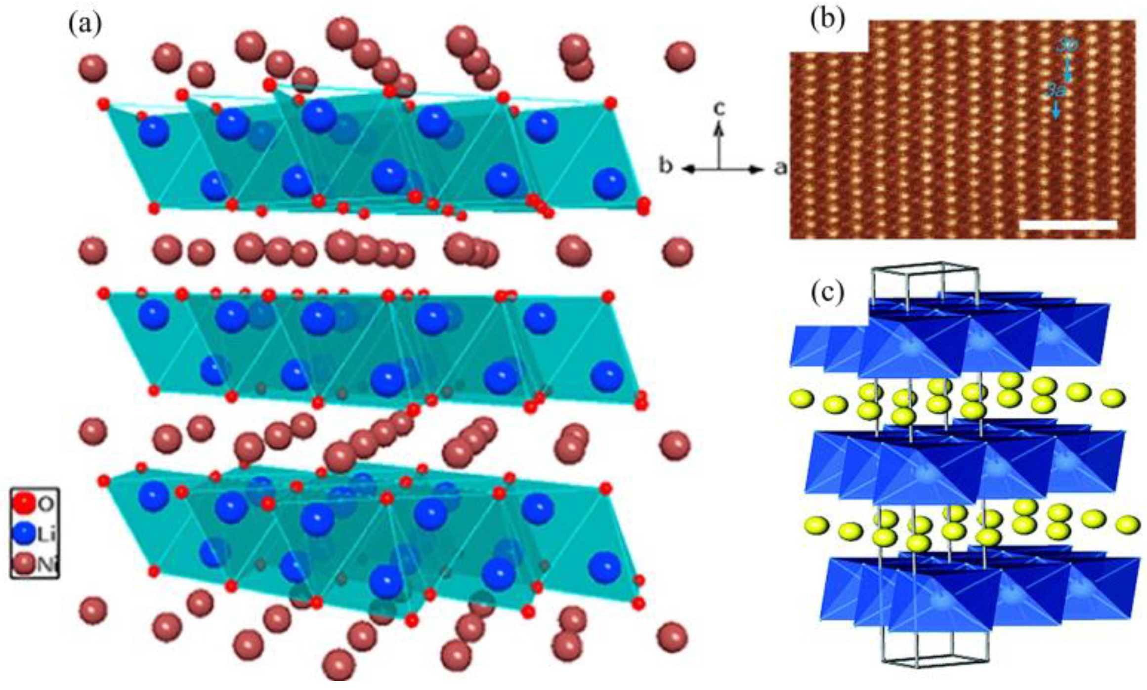
NRLO and LRLO are layered oxides, which have a rhombic α-NaFeO2 type with the R 3 m space group and hexagonal layered structure. Transition Metal (TM) ions and Li ions are usually located on 3a and 3b in the structure and are arranged following [0 0 1] [13], as shown in Figure 2a,b. Since lithium in LIBs is mainly stored in the cathode material, and in the layered metal oxide structure, the closed filled oxygen framework allows the unrestricted passage of lithium ions [14] (Figure 2c). Therefore, the lattice oxygen on the surface of the material will be detached due to oxidation to form gaseous oxygen (O2), resulting in mass loss of the cathode material, and the generated oxygen will react with the electrolyte, generating a large amount of reaction heat. However, different TM ions have slightly different effects on the structure. The redox reactions between Ni2+ and Ni3+ and between Ni3+ and Ni4+ can provide additional capacity. Co accelerates the delamination of the material structure through the redox reaction between Co3+ and Co4+; Mn4+ can make the structure more stable due to its electrochemical inertness [15]. Manthiram et al. [16] measured the energy bands of these three ions and found that Mn ions in the layered structure are the most stable and Co ions are the most active.
Structural evolution in layered metal oxides significantly influences their thermal stability. For NRLOs, their crystal structure is destabilized with increasing Ni content due to the strong oxidizing of Ni4+ under high states of charge (SOC). Upon full charging, TM ions in the layered framework are oxidized to high valence states, which become thermodynamically unstable at elevated temperatures. To maintain charge neutrality, lattice oxygen is released as O2 gas through anionic redox reactions. The O2 that forms readily interacts with the combustible gas present in the liquid electrolyte and the lithiated graphite of the anode, generating a large amount of heat, and the Ni content in the NRLO is obviously more than other TM ions. Therefore, the degree of Ni4+ reduction reaction determines the thermal stability of the cathode. In addition, high Ni content can also cause structural anisotropy, leading to the generation of microcracks. Therefore, for layered metal oxides, the thermal stability can be significantly enhanced by optimizing the types, concentration distributions, and synergistic interactions of TMs [13,14,15], as shown in Figure 2.
2.
Cation mixing
Cation mixing is an important reason for the limiting of the development of layered oxides. Since the radii of Li ions and Ni ions are similar, when Li ions diffuse along the diffusion channel, the Li vacancies in the structure are easily filled by Ni ions in the TM layer, forming a new TM oxide accompanied by the generation of O2, as shown in Figure 3. Cation mixing not only occurs during the production of cathode materials, but also occurs during the electrochemical process and has a significant impact on the thermal stability of the cathode. When a LIB is charged, due to the transfer of a large number of Li ions from the positive electrode to the negative electrode, excess Li vacancies on the positive electrode will induce cathode decomposition to maintain balance. This process is also accompanied by the release of O2 and the formation of TM oxides. Taking Li+/Ni2+ cation mixing as an example to explain the thermal failure process
3LixNiO2 (layered) → 3LixNi2O4 (spinel) + NiO (rock-salt) + xLi2O
LixNi2O4 (spinel) → 2NiO (rock-salt) + x/2Li2O + (4 − x)/2O2
3LixNiO2 (layered) → 3NiO (rock-salt) + 3x/2Li2O + (6 − 3x)/4O2
For the case where x = 1, the reaction enthalpy of the above reactions is 150~300 kJ/mol, 271 kJ/mol, and 500~800 kJ/mol, respectively.
The above process shows that the migration of TM ions will lead to the phase transition of the layered structure to the spinel phase accompanied by the release of oxygen. Studies [17,18] elucidated this process from a lattice-structure perspective, revealing distinct effects of transition metal (TM) ion migration on the mechanism. In the nickel-rich cathode, the migration of Ni dictates the onset temperature for oxygen release at lower temperatures, whereas at higher temperatures, the migration of Co and Mn establishes the temperature range for oxygen release. In lithium-rich cathodes, the migration of Ni is associated with the initial temperature of thermal decomposition, whereas the migration of Mn significantly influences both the release of oxygen and heat.
The mixing of cations destroys the structure of the cathode, causing irreversible damage, thereby accelerating the decomposition speed of the cathode material. However, it was found that when the TM and O are combined (TM-O-TM), the formation at different positions has different effects on thermal stability. Kanamori et al. [19] found through research that 180° Ni-O-Ni can provide more energy than 90° Ni-O-Ni in magnetic interaction, which improves the thermal stability of the cathode.
Figure 3. Cation migration process, (a) Charged LiMO2 (R 3 ¯ m: layered, M = Ni, Co, Mn), (b) M cation migration (mostly Ni) during phase transition from layered to LiM2O4 type spinel (A, B-the positions of M cation within the crystal lattice), (c) LiM2O4-type spinel (Fd 3 ¯ m), (d) M3O4-type spinel (Fd 3 ¯ m). “Reproduced with permission [18]. Copyright © 2014, American Chemical Society”.
Energies 18 04240 g003
3.
Interfacial reactions
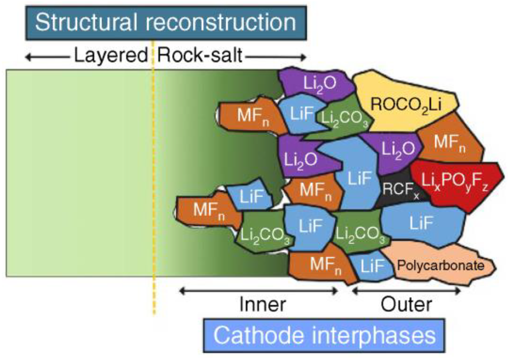
The chemical evolution at cathode particle boundaries in LIBs constitutes a critical factor determining thermal stability, particularly in high-voltage systems (>4.3 V). Organic carbonate-based electrolytes employing lithium hexafluorophosphate (LiPF6) as the conducting salt exhibit anodic decomposition above 4.7 V, generating hydrofluoric acid (HF) through hydrolysis. This HF generation accelerates transition metal dissolution from cathode surfaces, with Ni2+/Co2+ leaching rates increasing threefold at 60 °C. Concurrently, electrolyte decomposition forms a solid–electrolyte interphase (SEI) layer with heterogeneous thickness distribution (15–50 nm standard deviation), exposing a 15–30% additional cathode surface area. This exposure exacerbates intragranular crack propagation and interfacial impedance growth. During layered oxide synthesis (e.g., NCM811), residual lithium precursors adhere to particle surfaces and react with ambient CO2/H2O to form hygroscopic LiHCO3, which decomposes under electric fields (>106 V/m) to generate CO2 gas. The resulting cell swelling (>5% volume expansion) induces mechanical electrode separation, while lattice oxygen release triggers exothermic electrolyte reactions (ΔH = −800 J/g for EC oxidation) [20]. As illustrated in Figure 4, this synergistic degradation mechanism involving surface chemistry and bulk structure breakdown ultimately governs the thermal safety margins of layered oxide cathodes.
Figure 4. Schematic representation of the microstructure and chemical composition of surface degradation products [21].
Energies 18 04240 g004

2.1.2. Path to Elevate Thermal Stability

In response to the common thermal failure mechanisms listed above, researchers have explored many methods to improve them through experimental research. Their methods can be summarized and divided into three categories: the internal doping of materials, material surface attachment, material structure optimization (single crystal, polycrystalline); these methods can improve cation mixing, boundary reactions, and thermal runaway caused by structural changes. Of course, they do not correspond one to one, but are intertwined and integrated.
  • Internal doping
Doping refers to the mixing of multiple substances together. In the fields of chemical industry, materials, etc., doping usually refers to the intentional incorporation of a small number of other elements or compounds into this material or matrix to improve the performance of a certain material or substance. Among them, the cost and toxicity of Co limit its large-scale use in energy storage, and the deterioration of the structural stability of Ni oxide during cycling has increased researchers’ concerns. Table 1 lists the effects of common element doping on the thermal stability of layered oxides.
Adding elements to the Li position can effectively enhance the thermal stability of the cathode material. Taking the Y element as an example, doping Y can effectively solve the problem of the poor structural stability of Ni oxide during cycling. This is because Y3+ (90 pm) has a larger ionic radius than Ni2+ (62 pm) and the G of Y oxide is significantly larger than Ni oxide. In addition, the Li-O-Y bond formed by divalent Y occupying the Li site is more stable than Li-O-Li. Under the joint influence of the two, the stability of the structure is enhanced. The element occupying the Li position usually plays a key supporting role in the structure. This phenomenon is called the “pillar effect”. It can be said that the elements occupying the Li position play a positive role in the thermal stability of the material. Doping at the TM site can effectively improve the cycle stability of the cathode and reduce thermal runaway caused by crystal cracking. Taking the Zr element as an example—the chemically inert Zr4+ replaces Ni and Co, hinders the migration of Ni2+ throughout the process of charging and discharging, and expands the lithium-ion layer. This phenomenon is called the Zr doping effect. At present, Guo [22] usually performs dual element doping to achieve the combination of advantages and the complementation of disadvantages. For example, F/Al co-doped NCM shows a 71% reduction in heat flow, an increase in heat release onset (peak) temperature of 70 °C (63 °C), and the thermal stability is significantly better than that of F or Al alone.
Table 1. Effect of element doping on thermal stability.
SiteMaterialDopingCharging Voltage (V)Heat FlowHeat Release Onset
(Peak) Temperature
Ref.
LiLiNi0.8Co0.1Mn0.1O2Y4.3
4.5
−70%+10 °C (+12 °C)[23]
−75%+5 °C (+10 °C)
Li1.2Ni0.54Co0.13Mn0.13O2Mg4.8−39%+55 °C (+14 °C)[24]
LiNi0.6Co0.05Mn0.35O2Na4.5−20%+25 °C (+24 °C)[25]
NiLiNi0.8Co0.2O2Ce4.5−45%+10 °C (+18 °C)[26]
LiNi0.8Co0.2O2Ti4.3−82%+87 °C (+82 °C)[27]
LiNi2O2W4.3−34%+10 °C (+10 °C)[28]
CoLixNi0.8Co0.2O2Mg5.0−82%Consistent[29]
Li1.2Ni0.13Co0.13Mn0.54O2Al4.8−40%Consistent[22]
MnLi[Ni0.45Co0.1Mn0.45]O2Zr4.6−38%+50 °C (+37 °C)[30]
LiNi1/3Co1/3Mn1/3O2Ti4.5−34%+23 °C (+18 °C)[31]
Mn/CoLiNi1/3Mn1/3Co1/3O2Mg4.3ConsistentConsistent[32]
Mn/Co/MnLiNi0.85Co0.1Mn0.05O2Nb4.3−23%Consistent[33]
LiNi0.6Co0.2Mn0.2O2Mg4.3−41%+25 °C (+35 °C)[34]
Zr4.3−18%+10 °C (+15 °C)
LiNi0.9Co0.05Mn0.05O2W4.3 V−16%+10 °C (+10 °C)[28]
OLiNi0.8Co0.15Mn0.05O2W4.3 V−21%+23 °C (+25 °C)
Li1.2Ni0.13Co0.13Mn0.54O2F4.8 V−65%+20 °C (+42 °C)[22]
2.
Surface coating and doping
Since the reaction between the positive electrode and the electrolyte and the reaction between the remaining surface lithium salt and the air can lead to severe thermal runaway, researchers prevent the positive electrode surface from contacting the outside world by covering or doping the surface. Common coating materials include fluorides (CF3H2OH, LaF), silicides (SiO2), metal oxides (CeO2, Li2WO4), oligomers (BMI/TCA [35,36,37,38]). Among them, CF3H2OH can consume the remaining lithium salt on the surface and form a polymer coating composed of [CF3H2OH]n and LiF on the surface of the positive electrode. This coating not only significantly inhibits surface degradation exchange by inhibiting Li+/H+, but also avoids side reactions between the NCM and the electrolyte [39]. SiO2 exhibits strong HF-scavenging capacity, which not only enhances lithium-ion diffusion kinetics but also reduces interfacial charge-transfer resistance [35]. CeO2 effectively suppresses Li/Ni cation mixing in NCM cathodes and inhibits the lattice oxygen evolution to O2 [36], while BMI/TCA forms a protective cathode-electrolyte interphase (CEI) during initial charging, thereby reducing electrolyte decomposition and O2 release [38]. Compared with surface attachment, surface doping can effectively change the surface lattice parameters, reduce lithium-ion transfer resistance, and inhibit the reaction between the surface and the electrolyte. Table 2 lists the thermal properties of common surface coating and doping elements.
3.
Structure optimization
Although element doping and surface attachment can effectively solve the thermal failure problem of the positive electrode, these methods lose a part of the battery capacity and increase the cost due to the addition of additional materials. Therefore, structural optimization is a powerful means to reduce costs and increase efficiency. Currently commonly used structural optimization strategies include crystal engineering, single crystal optimization, core–shell structure, and concentration gradient [46,47,48]. In addition, the development of adaptive thermal control systems for lithium-ion batteries in recent years has facilitated low-temperature cold starts and charging processes, serving as an effective solution to address cathode thermal failure issues [49,50,51,52].
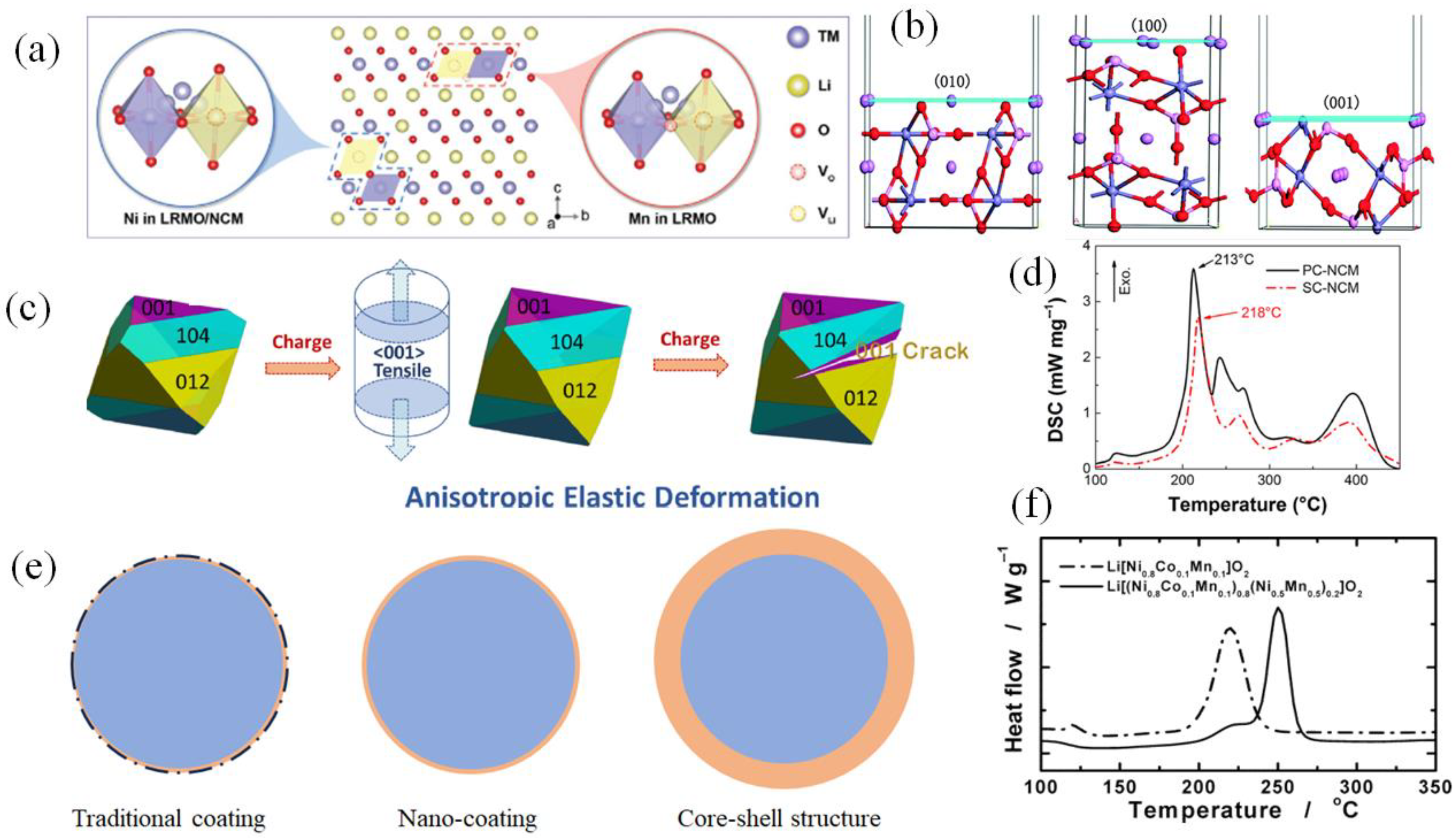
Among them, crystal engineering is to solve problems such as reduced compaction density and increased impurity content caused by element doping and other methods. In layered metal oxides, the [0 1 0] plane typically exposes more edge sites or defects, which serve as “fast channels” for the intercalation-deintercalation of lithium ions. In contrast, the [0 0 1] plane usually corresponds to the basal plane of the layered structure, featuring a more tightly packed atomic arrangement and stronger interlayer bonding. Consequently, the former exhibits superior electrochemical performance, while the latter demonstrates better thermal stability. The crystal structures of the [0 1 0], [1 0 0], and [0 0 1] planes in layered metal oxides are illustrated in Figure 5b. Therefore, reasonable control of the distribution and number of different planes through crystal engineering can effectively enhance the thermal stability of the cathode while maintaining good electrochemical performance. Guo et al. [53] synthesized layered oxides with [0 1 0] planes and found that compared with the raw materials, the part that undergoes phase change when heated to the same temperature is significantly smaller, and the structural stability is significantly improved.
Single crystal optimization is to solve the problem of polycrystalline NCM materials being prone to collapse during the synthesis process, resulting in an increase in the contact area with the electrolyte. The particle density of single crystal materials is much higher than that of polycrystalline materials [54], making it easier to maintain the structure under high compaction densities. Due to the excellent mechanical properties of single crystal materials, the occurrence of intergranular cracks will also be suppressed [55]. Figure 5c illustrates that both intergranular and intragranular cracks tend to initiate and propagate via interlayer splitting along the [0 0 1] direction. To a certain extent, this mechanism can alleviate the release of thermal stress, thereby enhancing the material’s thermal stability. Through Differential Scanning Calorimeter (DSC) measurements, Pang [56] and others found that single crystal cathodes release less heat than polycrystalline materials, and the thermal decomposition temperature also increased by 5 °C, as shown in Figure 5d. The above shows that single crystal optimization can provide better thermal stability for LIBs.
Figure 5. (a) Schematic diagram of element doping coordination. “Reproduced with permission [57]. Copyright © 2023 Wiley”, (b) Structural comparison of different planes, (c) Anisotropic elastic deformation along the crystallographic direction of primary particles. “Reproduced with permission [55]. Copyright © 2021 Elsevier”, (d) NCM polycrystalline/single crystal thermal stability comparison. “Reproduced with permission [56]. Copyright © 2020 Elsevier”, (e) Different coating methods, (f) DSC traces of Li[(Ni0.8Co0.1Mn0.1)0.8(Ni0.5Mn0.5)0.2]O2 and Li[Ni0.8Co0.1Mn0.1]O2 at charged state to 4.3 V. “Reproduced with permission [58]. Copyright © 2005, American Chemical Society”.
Energies 18 04240 g005
The core–shell structure was proposed to solve the problems of the uneven distribution of traditional surface coatings (from tens to hundreds of nanometers) on the cathode surface and poor stability of ultra-thin nano-coatings (1~10 nm), as shown in Figure 5e. The thickness of the core–shell structure is mostly in the order of microns, which is a thick coating. However, a uniform thick coating will cause gaps in the coating during long-term cycles, leading to a decrease in performance. Therefore, a concentration gradient layer was proposed, that is, there is a gradient change in TM ions in the coating. Sun et al. [58] proposed the core–shell structure in the layered structure cathode for the first time in 2005, and clearly found that the thermal stability was improved (as shown in Figure 5f). The core–shell structure significantly enhances the thermal stability of catalysts by physically isolating components through the shell layer, and modulating electronic structures at the interface, thereby effectively suppressing aggregation, and phase transformations at elevated temperatures. Since then, core–shell structure and concentration gradient have become one of the methods to improve the thermal stability of LIBs.

2.2. Spinel Oxide

Spinel oxide has gradually attracted researchers’ attention due to its low cost and environmental friendliness. As a representative of spinel, LMO is considered to be the most promising cathode material. LIBs using LMO as the cathode usually have a larger energy density (148 mAh/g) and higher voltage (4.7 V). However, its disappointing cycle life and thermal stability are problems that researchers urgently need to solve. These defects are mainly caused by the Jahn–Teller effect, Mn dissolution, and electrolyte decomposition. To solve these problems, researchers have proposed ion doping and coating attachment. The thermal failure mechanism and improvement methods will be described below based on the above issues.

2.2.1. Thermal Failure Mechanism

  • Surface distortion and Jahn–Teller distortion
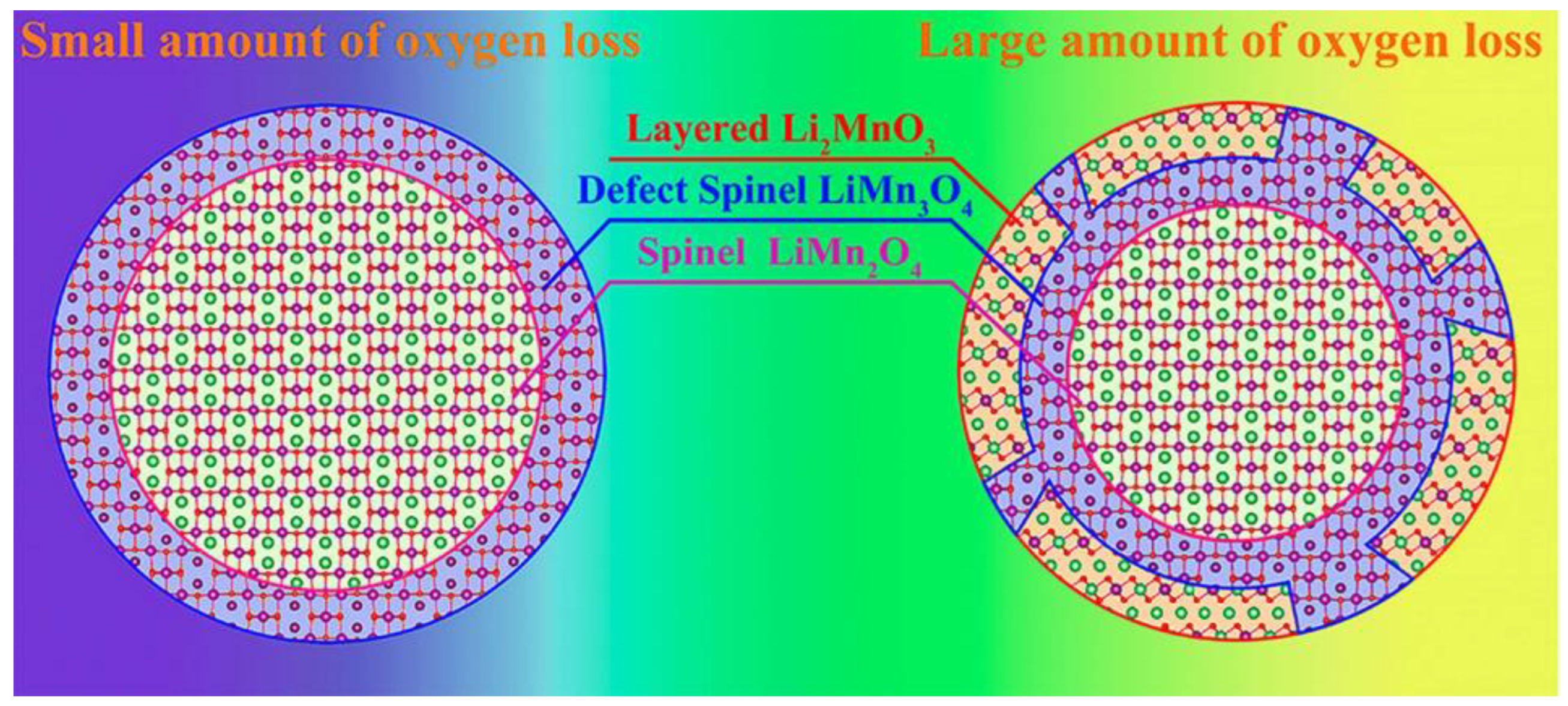
Surface distortion refers to the transformation of the surface atomic structure from a spinel structure to a layered structure during cycling, leading to the attenuation of cycling performance and thermal stability. This phenomenon is more serious at high voltages (3.0 V–4.9 V). When the voltage rises to 5.1 V, the surface distortion extends to the interior to cause Jahn–Teller distortion [59]. Ben et al. [60] revealed via STEM that surface distortion in spinel LMO induces the formation of intermediate LiMn3O4 defect spinel and subsequent transformation to layered Li2MnO3 (Figure 6). However, the transformation of this process requires Mn4+ to migrate from an octahedral site to an intermediate tetrahedral site in the initial spinel structure to form Mn3+/2+. To maintain the electrical neutrality of the structure, oxygen ions break away to form O2. Since Mn3+ has a high diffusivity in the spinel structure and preferentially occupies tetrahedral sites, as oxygen release increases, Mn3+ in the tetrahedron is prone to a disproportionation reaction: 2Mn3+ → Mn4+ + Mn2+. The divalent Mn ions remain in the tetrahedral sites, while the tetravalent Mn ions return to the octahedrons, resulting in the formation of layered oxides. In general, this surface distortion process is accompanied by the formation of a large amount of oxygen, which poses a huge threat to the safety of the battery.
2.
Mn dissolution
Manganese dissolution, caused by Mn2+ leaching from disproportionation reactions, irreversibly damages cathode structures via active material depletion and polarization. In graphite-LMO LIBs, dissolved Mn2+ deposits on anodes as metallic Mn, accelerating electrolyte decomposition and self-discharge. Studies reveal that lithium salt additives influence Mn dissolution: while all salts induce leaching during charging, LiFP6 exacerbates HF-mediated dissolution during discharge due to its instability. High temperatures accelerate dissolution, with Mn4+/Mn3+ ratios shifting from 62.83%/37.17% (air exposure) to favor Mn2+ generation. Deposited MnO/MnF2 compounds on cathodes cause severe polarization and capacity fading [60,61].
3.
Interfacial reactions
The boundary chemical reaction of spinel is like that of layered metal oxides, and there are problems such as the spontaneous generation of the CEI [3,62] when the cathode is in contact with the electrolyte, resulting in crystal cracks. It typically intensifies significantly under high-temperature (>50 °C) and high-voltage (>4.3 V) conditions. Since the HF generated by the decomposition of LiPF6 will corrode the active material in the cathode, the following reaction occurs [63,64]:
LiPF6 ↔ LiF + PF5
H2O + PF5 → 2HF + POF3
2LiMn3+Mn4+O4 + 4HF → 3Mn4+O2 + Mn2+F2 + 2LiF + 2H2O
Among them, MnF2 and LiF2 will be deposited on the cathode surface, causing electrode polarization and an increase in the cut-off voltage. When the cut-off voltage rises to 5.0 V, the resistance composed of CEI and SEI will increase by 400%. In addition to the decomposition of LiPF6, LiCO3 will also be oxidized and decomposed to generate CO2 in a high SOC state. The reaction is as follows [65]:
2Li2CO3 + LiPF6 → 3LiF + CO2 + POF3
In addition, the active materials on the surface are oxidized to methane by the oxygen released by the decomposition of the electrolyte and a small amount of moisture in it. Methane will be further oxidized under high voltage, eventually producing CO2. The reaction can be expressed as [3,66,67]
CH4 + O2 → H2O + CO + H2
2H2 + O2 → 2H2O
2CO + O2 → 2CO2
The above are all oxidation reactions, so a large amount of heat will be released during the reaction, posing a serious threat to the safety of the battery.

2.2.2. Path to Elevate Thermal Stability

  • Element doping
As with layered oxides, elemental doping is one of the most effective ways to improve stability. Because stronger TM-O chemical bonds can enhance the lattice energy, thereby reducing Mn dissolution, fewer Mn3+ ions can improve the stability of the structure and weaken the Jahn–Teller effect [68]. Currently, common doping elements are usually metal elements surrounding manganese atoms, such as Ti, Fe, Co, Ni, etc., because their similar radii will not cause significant structural changes due to substitution. However, aluminum (Al) is the most studied and considered the most effective doping element because Al is low-cost, environmentally friendly, and has low density. Angelopoulou [69] synthesized Al-doped LMO and used X-ray Diffraction (XRD) to characterize the structure of LMO. He found that Al doping did not change the structure of LMO, but the diffraction peak shifted to the right. This is because the ionic radius of Al3+ (0.57 Å) is smaller than that of Mn3+ (0.66 Å) and Mn4+ (0.6 Å), and partial Al substitution will cause the lattice parameters of LMO to decrease. Han [70] also observed that Gd doping changed the unit cell parameters, reducing the unit cell size from 8.2419 Å to 8.2375 Å.
2.
Surface coating
Surface coating is an important method to improve the stability of cathode materials. It can inhibit the dissolution of Mn ions and inhibit phase change. The corrosion of the positive electrode surface by HF generated by the decomposition of the electrolyte will also be effectively controlled. Amatucci [71] and others successfully improved the stability of the cathode material under high-temperature charging by coating the Li1+xMn2−xO4 surface. To further improve stability without losing electrochemical performance, researchers have tried a variety of coating materials, including metal oxides (MgO, Al2O3, ZrO2, ZnO), fluorides (FeF3, LaF3), LixCoO2 (0 < x ≤ 1), complexes, etc. Among them, metal oxides can effectively improve the lattice parameters, reduce oxygen activity at high potentials and absorb HF. Fluorides are easier to synthesize than metal oxides, and their stable structures can inhibit the decomposition of SEI and have good thermal stability. The Co ions in LixCoO2 can reduce the cation disorder caused by Mn dissolution; the complex mainly has good resistance to phase degeneration [72]. Table 3 lists the effects of different coating materials on thermal stability.
3.
Structural optimization
Like layered oxides, structural optimization methods such as shell-core structures also exist in spinel oxides. At present, the main challenge of LMO batteries is that structural distortion induces capacity fading or structural failure. Therefore, the use of the core–shell structure can effectively slow down the dissolution of Mn and maintain the structural form. Due to the excellent electronic conductivity and stable structural properties of carbon, nano-conductive carbon is synthesized through a mechanical fusion method and coated on the LMO cathode material to form a cathode with a core–shell structure [82]. Compared with the original LMO, the structural distortion is alleviated, and Mn dissolution is also significantly reduced. In addition, it can prevent direct contact with the electrolyte from corroding the positive electrode.

2.3. Polyanionic (Olivine) Oxide

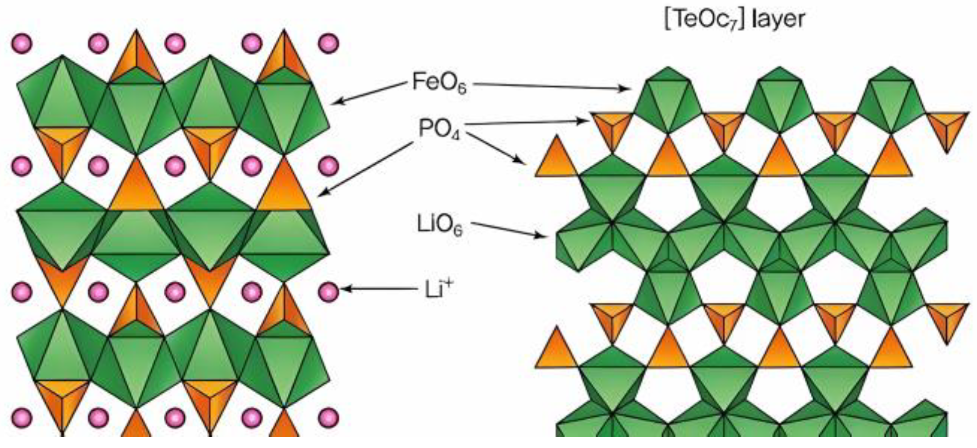
Polyanionic oxides are regarded as strong contenders as next-generation battery cathode materials due to their excellent stable structure and thermal properties, as well as significant electrochemical properties [83]. Its representatives include phosphate-based LiMPO4(LMP), (M = Fe, Co, Ni, Mn) and sulfate-based Li2M(SO4)2(LMS), (M = Co, Mn, Zn, Mg, Ni) [84]. Among them, LiFePO4 with olivine structure has been commercialized. LiFePO4 has the Pnma space group. The O atoms in the crystal structure are packed in the form of a slightly twisted six-sided tight structure. Fe atoms and Li atoms both occupy the center position of the octahedron, forming a FeO octahedron and a LiO octahedron. P atoms occupy the center position of the tetrahedron, forming a PO tetrahedron, as shown in Figure 7. The twisted octahedral lithium coordination polyhedron shares edges, forming a one-dimensional diffusion path parallel to the b-axis of lithium ions. Li2Fe(SO4)2 is a compound with two polymorphisms: monoclinic system and orthorhombic system. The difference between the two is mainly reflected in the polarization and reactive oxidation mechanism in the electrochemical process [85].
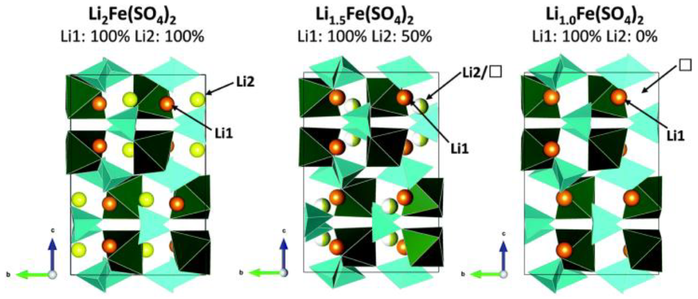
Li2Fe(SO4)2 crystallizes in the monoclinic P21/c space group, featuring a framework composed of FeO6 octahedra and SO4 tetrahedra (Figure 8). The edges of the two together form a one-dimensional diffusion channel for Li1 and Li2 [84]. Therefore, surface lattice oxygen oxidation leads to O2 release and thermal runaway. The key challenges for LMP/LMS materials are their inherently low electronic conductivity and sluggish Li+ diffusion. While structural optimization, metal doping, and conductive coatings can mitigate these issues, they offer limited improvement in thermal stability due to the intrinsic high thermal resilience of polyanionic oxides. For example, in LFP, the bond energy of the P-O covalent bond in the (PO4)3− poly anion is stronger than the M-O covalent bond in layered metal oxides or spinel oxides. Therefore, it can stabilize lattice oxygen when fully charged and avoid releasing O2 at high charge states. In addition, the arrangement of cations in LFP is different from that in layered metal oxides and spinel oxides. Fe2+ is located at the common corner of the octahedron, Li+ is distributed in the chain of the common edge of the octahedron, and P5+ is in the tetrahedron.
Upon lithium extraction, LFP exhibits a minimal volume change of 6.81%, indicating superior structural stability. Although LiCoPO4 (LCP) and LiMnPO4 share a similar structure, their thermal stabilities differ significantly. LCP and LMP are prone to release oxygen at high temperatures. This means that transition metal cations play an important role in the thermal stability of poly anionic cathodes. Hautier et al. [86] demonstrated that the electronic configuration of the cathode material is the primary determinant of its thermal stability through high-throughput ab initio calculations (a first-principles computational approach). In the octahedron of FeO6, a stable electronic configuration is formed due to the exchange stability produced by five parallel spin electrons [87], while the octahedra formed by Co and Mn have six and four electrons, respectively, so they cannot form a stable structure. Moreover, due to the oxidation state of Co2+ and Mn2+, more oxygen is released.
In summary, the thermal failure of cathode materials is primarily caused by surface oxidation, which leads to the detachment of lattice oxygen on the material surface, resulting in O2 and triggering thermal failure. The key to addressing this issue lies in understanding and controlling the role of transition metal cations and their impact on thermal stability. For example, Fe2+ in the FeO6 octahedron forms a stable electronic configuration due to the exchange stability generated by its five parallel spin electrons, while Co and Mn cannot form stable structures. Therefore, improving the thermal stability of materials can be achieved through structural optimization, such as metal doping and conductive coatings. However, these methods have a minimal impact on the inherent thermal stability of poly-anionic oxides. Additionally, the lithium-ion diffusion pathways on the material surface play an important role in thermal stability. For instance, the olivine structure of LiFePO4 can stabilize lattice oxygen during full charging and prevent the release of O2 at high charge states.

3. Anode

3.1. Carbon-Based Anode

Carbon-based anodes remain dominant in LIBs due to their abundant natural reserves, low cost, and superior lithium intercalation kinetics. The common carbon-based anode is graphite, and the intercalation of lithium ions between the layered structure of graphite enhances the stability and conductivity of the anode structure in two dimensions (Figure 9).
At present, most of the research on graphite anodes is conducted to improve electrochemical performance, and a small part of it studies its thermal stability. However, the thermal runaway of LIBs is mostly caused by the abnormal operation of the anode. Therefore, exploring the thermal stability of the anode is of great significance to the safety of LIBs. The thermal stability of the graphite anode mainly depends on the SEI film formed by the reaction of the graphite surface with the electrolyte [89]; on the other hand, the thermal failure of the graphite anode is mainly caused by boundary chemical reactions. Beyond conventional carbonaceous anodes, Li/C composite materials exhibit ultra-high theoretical capacity (3860 mAh/g for Li metal) and the lowest electrochemical reduction potential (−3.04 V vs. SHE), making them promising candidates for next-generation batteries. However, systematic investigations on their thermal stability remain scarce [6,90]. Therefore, the main reasons for the thermal failure of carbon-based anodes are the decomposition of the SEI and structural failure.

3.1.1. Thermal Failure Mechanism

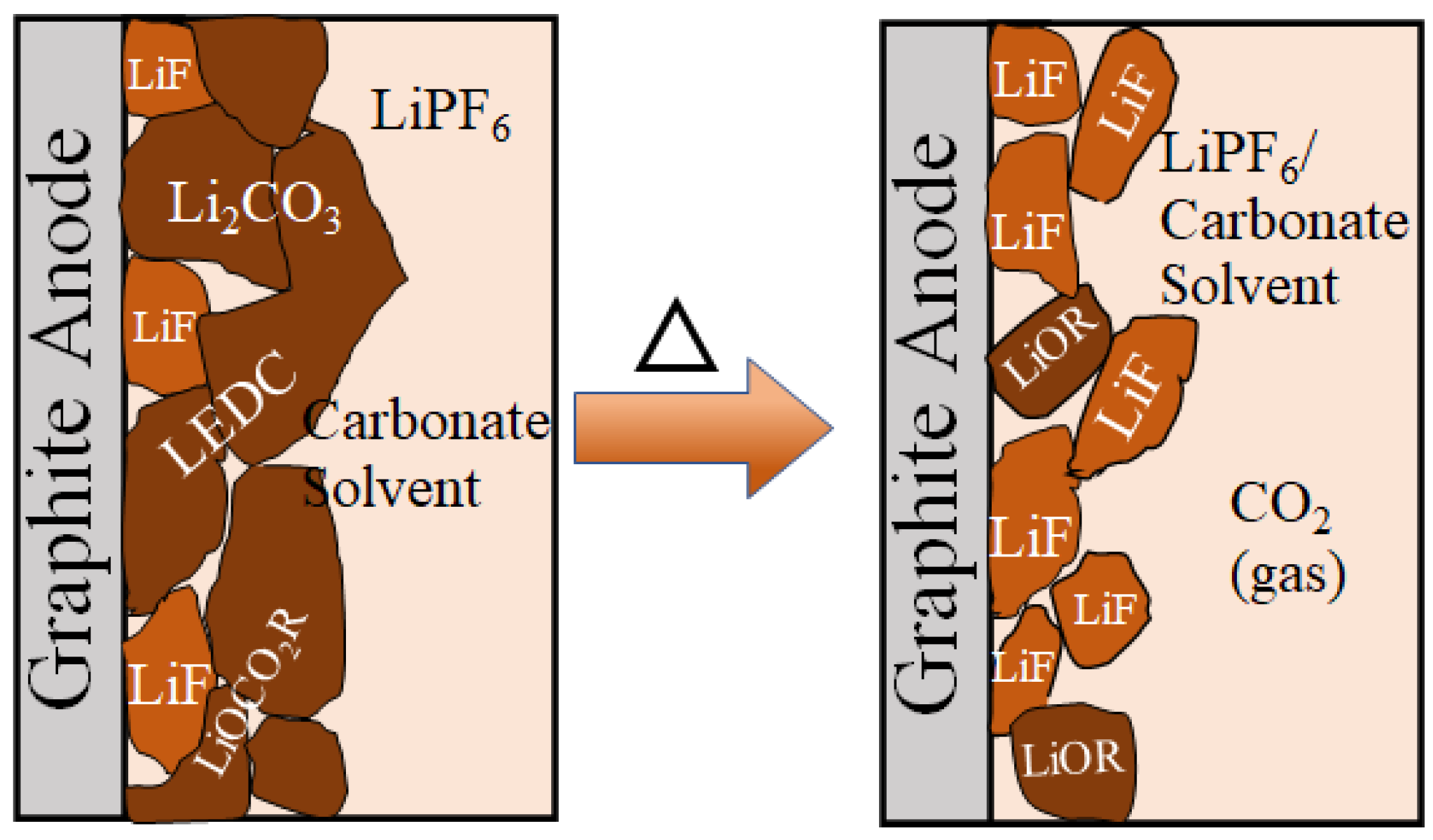
The working voltage of the graphite electrode is higher than that of the electrolyte, which causes the electrolyte to decompose. The decomposition products adhere to the surface of the graphite to form a thin film. Usually, the SEI includes lithium carbonate (Li2CO3), lithium methyl carbonate (LMC), and lithium ethylene dicarbonate (LEDC) [91]. At present, LiPF6 is used as the electrolyte in most LIBs, and SEI and LiPF6 are prone to react and decompose at high temperatures (80~100 °C). The possible reactions are as follows [92]:
LiPF6 + 2Li2CO3 → 2CO2 + 4LiF + F2PO2Li
Energies 18 04240 i001
Energies 18 04240 i002
Energies 18 04240 i003
Energies 18 04240 i004
The above reactions usually accompany the generation of gas, causing damage to the battery. Because the SEI can prevent the corrosion of the electrode by the electrolyte solution, when the SEI decomposes, solution molecules and lithium ions are intercalated into the graphite layer together, causing the graphite particles to fall off and the stability of the graphite structure to decrease, as shown in Figure 10. In addition, the O2 produced by the reaction of the electrolyte with the cathode surface will also contact and react with the lithiated graphite anode due to the decomposition of the SEI film, releasing a large amount of heat and posing a serious threat to the safety of the battery. In addition, the inactive materials in the anode also significantly affect the thermal stability.

3.1.2. Path to Elevate Thermal Stability

The thermal failure of graphite anodes primarily stems from interfacial boundary reactions. Enhancing thermal stability thus requires suppressing these reactions or reinforcing the SEI film stability. Strategies include atomic doping/surface coating to modify graphite’s surface properties, and electrolyte additives to strengthen the SEI film integrity. Park et al. [93] demonstrated that P/B elements-doping enhances graphite anode thermal stability by forming C-P/C-B bonds, which retard high-temperature graphite decomposition. Gribble et al. [94] protect the electrode from the destruction of the electrolyte by covering the graphite surface with PEDOT: PSS conductive adhesive. As the carbon additive is added to the adhesive, the area of the SEI that can be generated is increased, and the heat released by the decomposition of SEI can dissipate quickly, which can reduce the risk of thermal runaway. Rhee [95] used TiO2−x to modify graphite as the negative electrode material of LIBs, effectively inhibiting the thermal decomposition of the graphite anode. In general, the current methods to improve the thermal stability of the graphite anode can be divided into surface element coating and doping and electrolyte additives.
Surface coating and doping strategies for graphite anodes aim to mitigate electrolyte-electrode reactions and enhance SEI durability. Common coatings include ZrO2 (forming monoclinic crystals at high temperatures to suppress oxidation), carbon (retarding graphite exfoliation and acting as a sacrificial oxidation layer), and conductive polymers (e.g., PEDOT:PSS). While coatings physically impede Li+ intercalation-induced structural degradation, doping (e.g., with B/P) alters surface chemistry via C-dopant bonds to stabilize the graphite framework. Notably, adding carbon black to PEDOT:PSS adhesives reduces thermal stability due to an increased SEI formation area and exothermic decomposition. Doping-induced stability variations stem from differences in C-dopant bond energies.

3.2. Silicon-Based Anode

Owing to its limited theoretical capacity (372 mAh/g), commercial graphite fails to meet future energy storage demands. In contrast, silicon emerges as the leading graphite alternative due to its superior properties: ultra-high theoretical capacity (4192 mAh/g), low reduction potential (0.37 V vs. Li/Li+), abundant natural reserves, cost-effectiveness, and environmental compatibility for large-scale applications. However, the high-volume expansion rate (approximately 300%) of the silicon electrode during charging and discharging limits its electrochemical performance and brings uncertainty to the safety of the battery. At the same time, the SEI generated on the silicon surface has poor stability and is prone to permanent capacity loss.
Current strategies to mitigate silicon volume expansion and SEI degradation include designing nanostructured silicon (e.g., nano/porous silicon, composites) and modifying surface properties. Nanostructures mitigate volume-induced mechanical stress and increase the SEI formation area via their high specific surface area, but severe nano-Si agglomeration degrades local stability and cycling performance. To address nano-Si agglomeration, researchers have developed silicon nanofibers, nanotubes, and porous nanostructures. However, nano-silicon production remains cost-prohibitive and technically complex, undermining its viability for large-scale commercialization. Consequently, researchers are shifting toward cost-effective Si-based composites (e.g., Si/C) to address these challenges. The primary thermal failure mechanisms of Si anodes stem from structural collapse and SEI degradation.

3.2.1. Thermal Failure Mechanism

  • Structural characteristics
Crystalline silicon exhibits an F d 3 m space group and adopts a SiSi4 tetrahedral structure, wherein each silicon atom is tetrahedrally coordinated with four surrounding silicon atoms. While silicon generally demonstrates remarkable chemical stability, its utilization as an anode material in lithium-ion batteries (LIBs) triggers a distinct behavior: lithium atoms readily intercalate into the silicon lattice, with a single silicon atom capable of accommodating up to 4.4 lithium atoms. This intercalation leads to the formation of both crystalline Si-Li compounds (such as LiSi, Li12Si7, Li15Si4, Li22Si5) and amorphous LixSi (where x ranges from 0 to 3.75). Notably, the crystalline phase maintains a stable state, whereas the amorphous phase undergoes a transition to the crystalline phase during the anode’s lithiation process, resulting in an expansion of the cell volume. This volumetric increase induces fractures in the crystalline silicon, subsequently causing damage to the solid electrolyte interphase (SEI). Simultaneously, the continuous accumulation of stress further exacerbates the fracture of crystalline silicon particles, leading to additional electrode degradation [96].
2.
SEI decomposition
Like carbon-based materials, the SEI generated on the surface plays an important role in the thermal stability of silicon-based anodes. The composition of the SEI generated on the surface of the silicon-based anode is diverse. Taking the common EC: DEC electrolyte as an example, since the silicon surface is always covered with native oxide layer SiO2, the SEI contains reaction products of the oxide layer LixSiOy. In the electrochemical process, the hydroxyl (-OH) functional group at the end of SiO2 will form thermally stable substances such as LiOH and Li2O. In addition, the SEI contains a large amount of electrolyte decomposition products, such as Li2CO3 and LiF. The reaction is as follows:
(Sisurface+ 2e) + 2EC + 2Li+ → ([Sisurface–CH2CH2–Sisurface] or (Sisurface+ CH2CH2gas) + LiOCO2–CH2–CH2–OCO2Liprecipitate
The reaction between lithium carbonate and lithium hexafluorophosphate has been reported [92]. LiOH will react with trace amounts of water in the electrolyte and the generated CO2 to produce more water molecules, which in turn leads to the generation of HF. The possible reactions are as follows:
2LiOH + 2H2O → 2LiOH · H2O
2LiOH · H2O + CO2 → Li2CO3 + 3H2O
LiF + H2O → LiOH + HF
All the above reactions are accompanied by the release of heat, which further leads to the thermal decomposition of the SEI. The LEDC in the SEI will decompose to produce CO2 and C2H4 gas at temperatures above 50 °C [97], thereby triggering thermal runaway. The solid propionic lithium (CH3CH2CO2Li) and Li2CO3 produced by decomposition will cause changes in the components of the SEI, leading to a decline in performance [98]. Therefore, inhibiting the decomposition of the SEI is crucial for battery safety.

3.2.2. Path to Elevate Thermal Stability

The thermal runaway of silicon-based anodes is mainly caused by structural failure and SEI decomposition. Therefore, strengthening the structure and hindering decomposition have become effective means to improve thermal stability.
  • Structural optimization
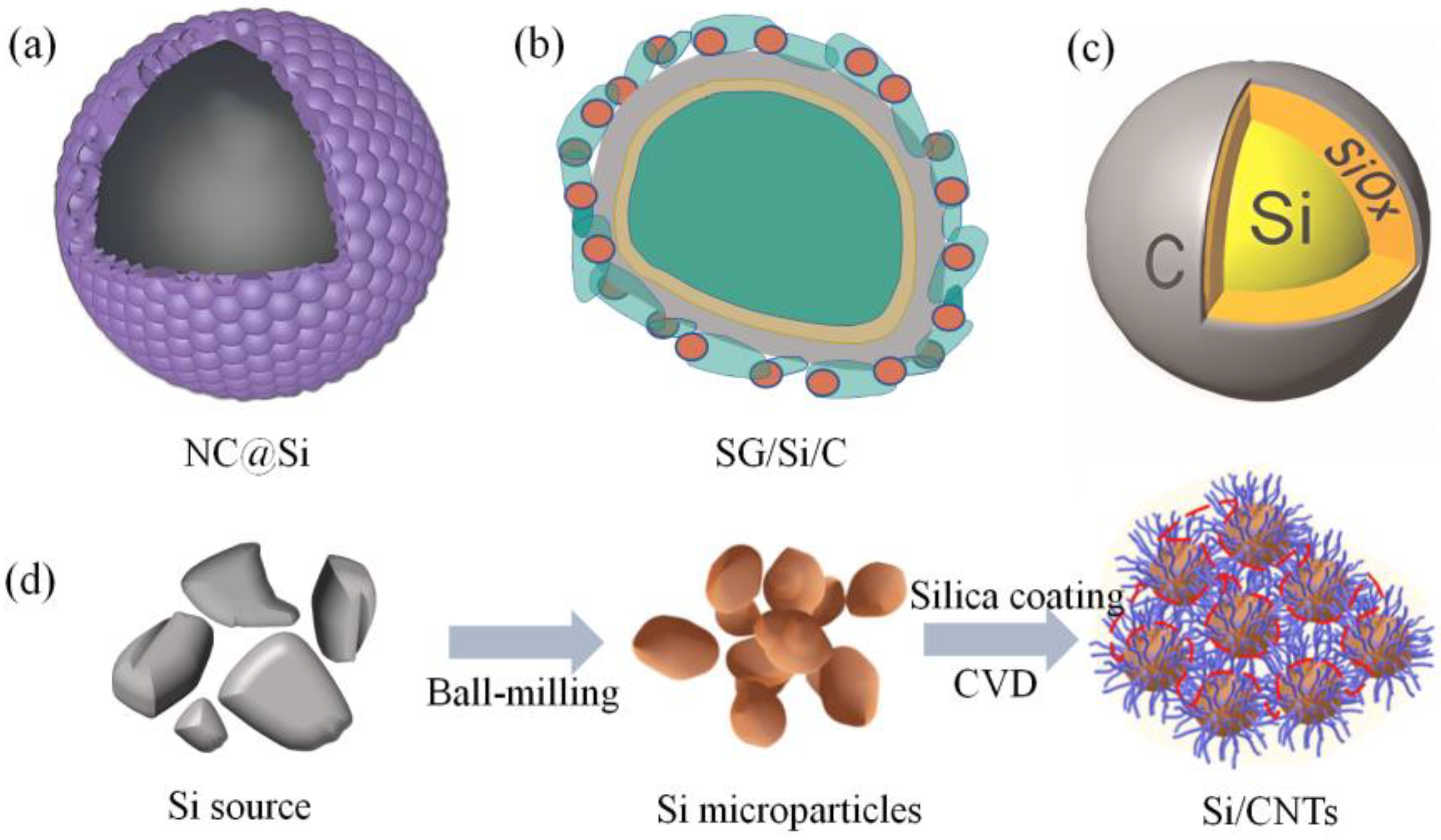
Structural optimization represents the most effective strategy to mitigate silicon anode volume expansion. These structural optimizations include the nanosizing of silicon (nano particles, nano pipelines, changes in silicon morphology (core–shell, porous, sea urchin), etc. [99,100,101]. Among them, nano-silicon can alleviate the impact of mechanical stress, and the larger specific surface area makes the SEI more stable, and the change in silicon morphology is to strengthen the suppression of volume expansion. Tian et al. [102] uniformly covered silicon on a nitrogen-containing carbon source (polydopamine, PDA), forming a shell-structured nano-silicon ball (NC@Si), as shown in Figure 11a. At high temperatures, the internal PDA can absorb most of the heat, maximizing the integrity of the silicon surface.
Figure 11b shows the silicon anode with a core–shell structure made by Zhou’s team [103]. The core–shell is composed of a composite material (SG/Si/C) consisting of graphite, nano-silicon, and disordered carbon. It has the advantages of the high capacity of silicon and high conductivity of carbon, and its stability at high temperatures is stronger than that of graphite. Jiang et al. [104] synthesized a double core–shell structure (Si@SiOx@C), which showed better stability at high temperatures, as shown in Figure 11c. Guan et al. [100] developed a low-cost sea urchin-like silicon-based anode, as shown in Figure 11d. The peripheral carbon nanotubes (CNT) are attached to the silicon particles in situ, improving the conductivity of the anode. At the same time, the buffer layer formed between CNT and Si can effectively suppress the expansion of the silicon anode. The table below lists the effects of different structures on thermal stability.
2.
Element doping
Element doping offers a cost-effective and scalable strategy to mitigate silicon anode volume expansion by stabilizing the SEI layer. As the SEI forms through electrode-electrolyte reactions, doping approaches are categorized into electrolyte additives and silicon surface modification, both aiming to enhance the stability of the SEI. As is well known, the electrolyte is the main contributor to the composition of the SEI, and effective modification can be achieved by doping additives in the electrolyte. At present, additives with functional groups such as fluorides (-F), nitriles (-C=N), and silanes are particularly favored in the research of optimizing electrolyte formulations [105], because these additives can form a heat-resistant SEI film to improve the thermal stability of the battery. Profatilova et al. [106] used the electrolyte additive fluoroethyl carbonate (FEC) to generate another layer of the SEI on the SEI surface to enhance the thermal stability of the silicon anode. Despite its superior performance, FEC’s propensity for gas evolution at elevated temperatures has driven researchers to explore alternative additives. Zhang et al. [105] demonstrated that silane polymer additive (TCN) promotes Li2CO3-rich SEI formation, enhancing anode stability. Meanwhile, Tan [107] revealed that (3-aminopropyl)triethoxysilane (APTES) forms a surface silica layer on Si particles to improve its thermal stability.
Beyond electrolyte engineering, surface functionalization via metal compound additives offers an alternative strategy for enhancing anode thermal stability. Kwok-ho [108] demonstrated that NiO/CuO surface coatings improve heat dissipation due to their high intrinsic thermal conductivity, thereby suppressing SEI degradation at elevated temperatures. Concurrently, Tao et al. [107] reported that TiN-modified Si anodes exhibit higher thermal conductivity than pristine Si.
Of course, in addition to the above two improvement methods, researchers also add adhesives between the electrolyte and the electrode and improve the adhesives to enhance structural stability and thermal stability. Yoon [97] found that using polyimide adhesives that decompose above 500 °C can slow down the thermal decomposition of the SEI when studying the thermal stability of silicon anodes. Profatilova [109] used Na-CMC as an adhesive, which increased the initial temperature of the heat release of the electrolyte. The polyglutamic acid (γ-PGA) synthesized by Guo [110] has excellent mechanical properties and can effectively maintain the integrity of the anode as an adhesive.

3.3. Lithium Metal Composite

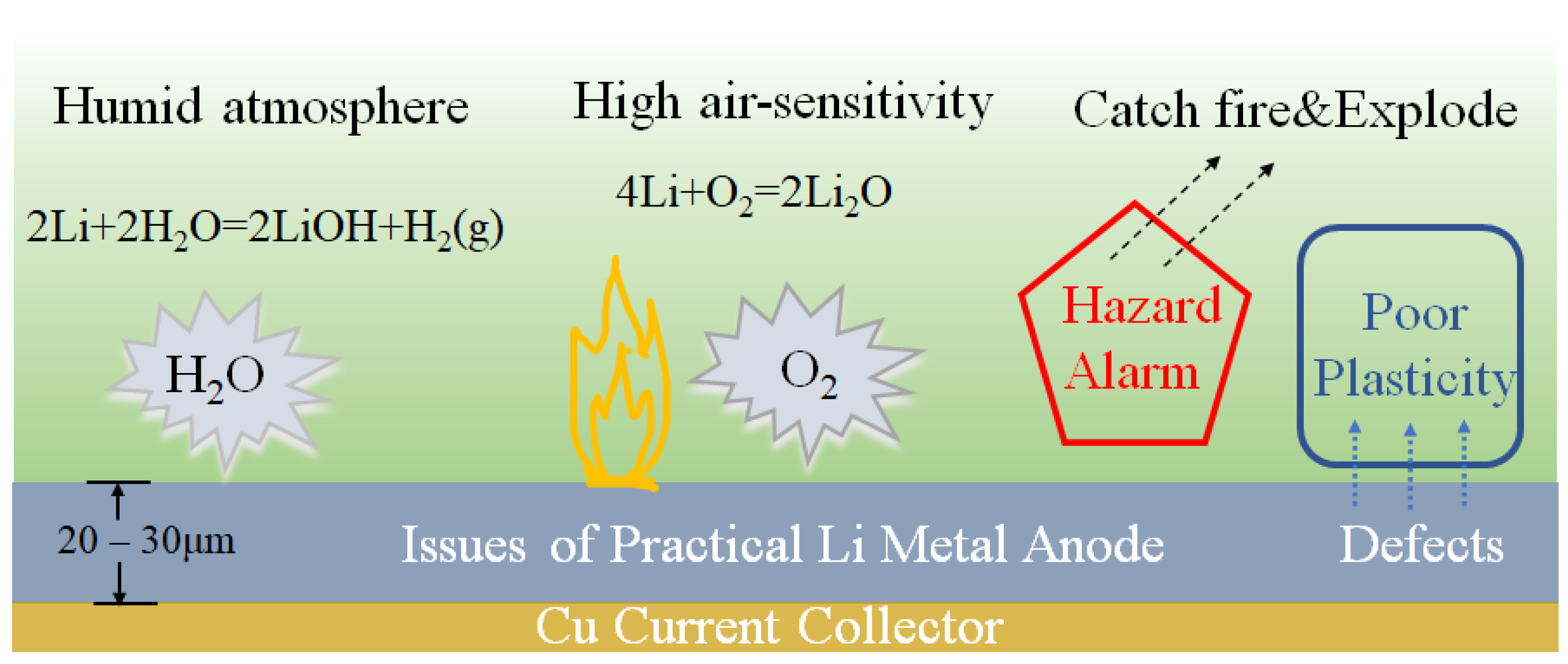
With the pursuit of higher capacity LIBs, lithium metal anodes, which have exited the historical stage, have once again come into researchers’ view. Lithium metal anodes are the next generation LIB anodes due to their high specific capacity (3860 mAh/g), light weight (0.534 g/cm3), and low redox potential (−3.04 V vs. the standard hydrogen electrode) [4,5,111]. The reason for the exit of lithium metal anodes from the historical stage is due to the uncontrollable thermal runaway induced by the proliferation of lithium dendrites. At present, more and more studies are being conducted on this issue, and several relatively recognized theoretical models have been proposed for the formation mechanism of lithium dendrites, but the thermal runaway caused by lithium dendrites cannot be completely controlled. At present, various means have been proposed to hinder the growth of lithium dendrites or directly eliminate lithium dendrites, including material modification, electrolyte additives, the use of solid electrolytes, and artificial electrolytes. In addition to the thermal runaway caused by lithium dendrites, an unstable SEI and a large amount of heat generated by the reaction of lithium metal anodes with electrolytes will also cause thermal safety issues. This article will elaborate on the thermal runaway mechanism and improvement measures from the above three aspects.

3.3.1. Thermal Failure Mechanism

  • Uncontrollable growth of lithium dendrites
The main reason for the thermal runaway of LIBs using lithium metal anodes is caused by the uncontrollable growth of lithium dendrites. There are many reasons for this uncontrollable phenomenon, mainly classified into the following: SEI rupture, lithium-ion deposition, difficulty in lithium-ion diffusion and large interfacial energy. Among them, SEI rupture will cause a new surface to react with the electrolyte, accelerating the growth of lithium dendrites; due to the uneven electric field at the contact surface of the electrode and the electrolyte, the local lithium ion concentration is too large, and lithium deposition exacerbates dendritization; the difficulty of lithium ion diffusion means that the number of lithium ions on the surface of the lithium metal anode is small, which leads to the growth of lithium dendrites; a larger interfacial energy will induce the formation of one-dimensional dendrites in the heterogeneous nucleation process. In general, the growth of lithium dendrites is a complex process. It is very difficult to eliminate lithium dendrites. Current research mainly focuses on controlling the growth of lithium dendrites within an acceptable range.
2.
Unstable SEI film
As mentioned in the carbon-based and silicon-based anodes, the SEI film generated in 1 M LiPF6-EC/DEC = 1:1 primarily consists of unstable inorganic compounds, including lithium carbonate, and the same is true for lithium metal anodes. At the same time, the uneven distribution of the SEI film and the stress caused by the volume change of lithium metal add insult to injury to the stability of the SEI film.
3.
Interfacial reactions
Due to the instability of SEI and the growth of lithium dendrites, the surface of lithium metal is extremely prone to contact with the electrolyte. The high reactivity of lithium causes intense chemical reactions, releasing a large amount of heat and thus inducing thermal runaway, as shown in Figure 12.
Through the analysis of the above thermal runaway mechanism, it is found that the decomposition of the SEI film is the main cause of the thermal runaway of the lithium metal anode. Therefore, how to improve the stability of the SEI film is the key to solving the thermal safety problem.

3.3.2. Path to Elevate Thermal Stability

So far, the requirements for the SEI of lithium metal anodes are a high ion diffusion rate, high structural stability, and high chemical stability. The methods to improve this SEI mainly include electrolyte additives, solid electrolytes, artificially synthesized SEI, and composite anodes.
  • Additives
Doping additives in the electrolyte can change the components of the SEI, and different components mean different characteristics. Gan’s team compared the thermal stability of lithium metal anodes in carbonate and ether-based electrolytes and found that the SEI film generated by ether-based electrolytes is more stable than the SEI film generated by carbonate electrolytes, and the lithium deposition on SEI has also been effectively improved. Therefore, to meet the high requirements for SEI, multi-characteristic additives have emerged. Common additives are divided into fluoride additives (LiFSI, LiODFB, FEC), nitride additives (LiNO3, KNO3, LiN3) and sulfide additives (Li2S8, Li2S5) [112]. Among them, fluoride additives decompose to form a thermally stable LiF-rich SEI, nitride additives enhance Li3+ diffusion and generate a robust Li3N-based SEI [113]. Sulfide additives reduce the SEI crystallite size, creating additional Li+ pathways and improving stability. Metal ion additives (e.g., A3+) exploit lithium’s alloying tendency to form Li-rich alloy films that facilitate ion transport and suppress dendrites. Ye et al. [114] showed that AlCl3 in the electrolyte synergistically inhibited dendrite growth via Al2O3 and Al colloids.
2.
Solid electrolyte
Liquid electrolytes usually contain flammable and toxic substances, posing significant safety risks during production and transportation. Moreover, liquid electrolytes have poor thermal stability and cannot effectively inhibit the growth of lithium dendrites. Compared with liquid electrolytes, solid-state electrolytes (SSE) perform better in inhibiting the growth of lithium dendrites and thermal stability. At present, researchers have developed a variety of SSEs, which can be divided into polymer electrolytes (PE) and inorganic solid electrolytes (SE). This discovery laid the theoretical foundation for the subsequent utilization of polymers as electrolytes in batteries. Common polymer electrolytes encompass polyethylene oxide (PEO), polycarbonate trimethyl ester (PTMC), polyvinylidene fluoride (PVdF), among others. However, single-molecule polymers typically exhibit inadequate thermal stability [115]. Specifically, in the case of PEO, the lithium-ion transmission rate is directly proportional to the mobility frequency of polymer chains, creating a conflict between conductivity and stability.
To address this challenge, synthesizing copolymers that integrate multiple material characteristics emerges as an effective solution. Recently, Wang et al. [116] incorporated 4-vinylbenzotrifluoride (TF3) into vinylidene carbonate (VC), resulting in a novel copolymer (MDPE) that demonstrated excellent deformation resistance, high conductivity, and an enhanced ability to suppress lithium dendrite proliferation. Additionally, combining polymers with liquid electrolytes yields a gel-like polymer that merges the high shear modulus of polymers with the high conductivity of liquid electrolytes. Nevertheless, this hybrid approach still falls short in inhibiting lithium dendrite growth and suffers from the inherent drawback of liquid electrolytes—easy decomposition at elevated temperatures.
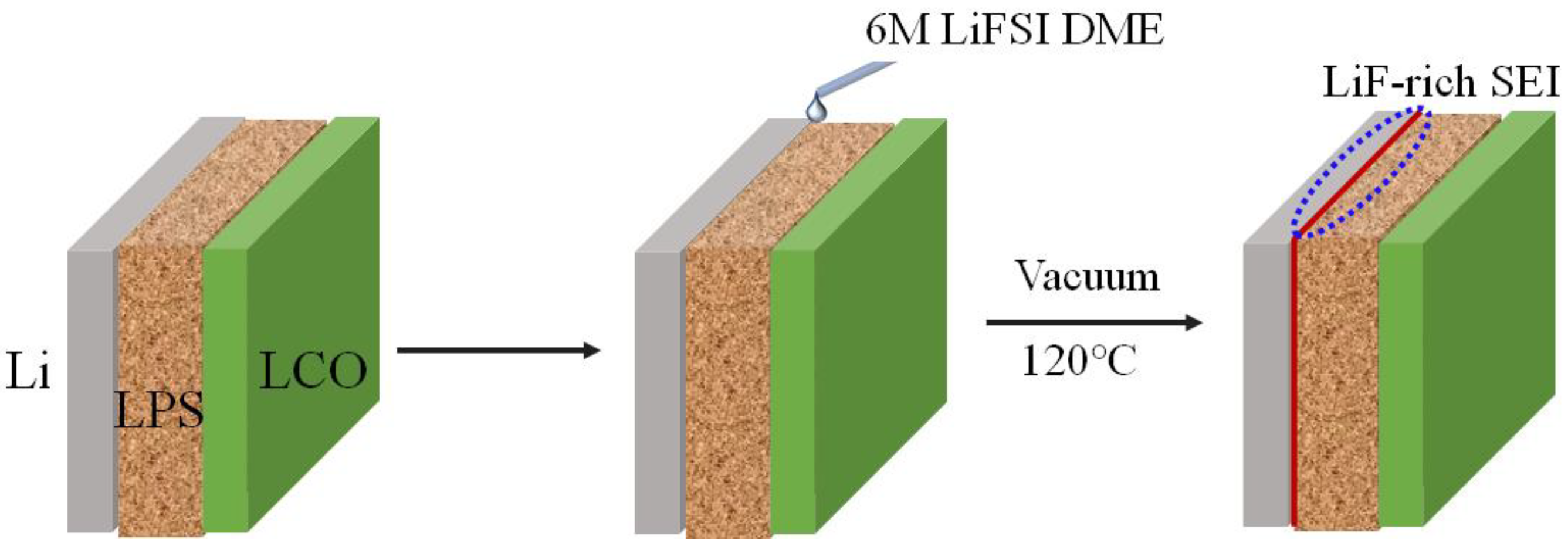
Solid electrolytes (SEs) are mainly inorganic, featuring mineral structures like perovskite and garnet. These materials are robust and flame-retardant, enhancing battery safety. However, SEs impede lithium-ion diffusion and have rigid surfaces that hinder safe anode contact. Studies show SE surface morphology affects lithium dendrite growth: lithium fills surface voids, causing stress that damages the SE and promotes dendrite proliferation. To address this, Fan et al. [117] inserted a LiF layer between lithium and the SE interface (Figure 13). Even if dendrites penetrate LiF, Li3PS4 (LPS) can consume excess lithium, suppressing further growth. Ceramic solid electrolytes are regarded as the premier inorganic solid electrolytes due to their minimal contact gaps with the anode and exceptional conductivity. Nonetheless, ceramic electrolytes cannot entirely prevent lithium dendrite growth stemming from gaps. Leveraging the excellent toughness of polymers, ceramic/polymer electrolytes are considered the optimal solid electrolytes, effectively addressing the issues of low conductivity and poor stability associated with SEs.
3.
Artificial SEI
The spontaneously formed SEI exhibits defects including uneven distribution, poor ionic conductivity, and susceptibility to decomposition. Artificially engineered SEI minimizes these issues and enables tunable component design. Currently, artificial SEIs are primarily polymer- or inorganic-based. Polymers, such as β-PVdF mitigate dendrite growth via high elasticity, while LiPAA-modified anodes reduce deformation [118,119]. Inorganics (e.g., LiF, Li2S, and Li3PS4) enhance interface stability; LiF-rich SEIs (Hou et al. [120]) and nanostructured LiF domains (Peng et al. [121]) suppress side reactions. However, artificial SEIs suffer from lower conductivity than natural SEIs, and complex synthesis hinders commercialization. While their laboratory-scale use will persist, artificial SEIs remain a promising strategy for controlling lithium dendrite formation and volume changes.
4.
Composite electrode
In addition to improvements on the electrolyte side, interface engineering on the metal side is also an effective method to stabilize the SEI film. Common ones are alloy composite electrodes composed of lithium and metal, and composite electrodes composed of lithium and carbon. The alloy composite electrode uses the plasticity and good electrical and thermal conductivity of the metal to provide a deposition substrate for lithium and alleviate the impact of anode volume changes. The 3D skeleton of Li/Al not only maintains the morphological structure of the anode but also suppresses the formation of surface lithium dendrites [122,123]. The porous structure of Li/Mg also plays an important role in maintaining stability and suppressing the growth of lithium dendrites [124]. In general, lithium metal interface engineering can effectively suppress the growth of lithium dendrites, and the stable structure significantly improves the thermal stability of the anode. Table 4 lists the studies on the thermal stability of the anode using different methods.
To sum up, the thermal failure mechanism of the anode is mainly the decomposition of the SEI, which leads to the reaction between the electrode and the electrolyte, accompanied by the release of heat, causing the internal temperature of the LIB to continue to rise. Improving the thermal stability of anode materials is conducted through methods such as element doping and surface coating—such as using high temperature tolerance, flame retardancy, and porosity strategies, using solid electrolytes to replace traditional liquid electrolytes to improve thermal stability and flame retardancy, improving the thermal stability of the anode and suppressing the thermal runaway through structural optimization of single crystals and polycrystals, as well as core–shell structure and concentration gradient design.

4. Separator

4.1. Microporous Separator

Microporous separators are widely used in LIBs due to their low production cost and excellent mechanical properties. Common microporous separators are mainly composed of polyolefins such as polyethylene (PE) and/or polypropylene (PP). However, these polymers have a lower melting point, which can easily cause safety issues such as battery short circuits caused by thermal shrinkage. Therefore, improvements need to be made to the microporous separator to enhance its thermal stability.

4.1.1. Thermal Failure Mechanism

The separator, as the least active component in the battery, can absorb the heat generated by overcharging. When the temperature rises to the shutdown temperature (ST), the separator softens and the micropores close to prevent ion transmission, thereby causing the battery to short circuit. However, the battery is a complex system, and even if it is short-circuited, it may continue to cause the temperature to continue to rise. When the temperature continues to rise to the melting temperature (MT), the separator will show obvious thermal shrinkage, the mechanical integrity will be significantly reduced, and the probability of a short circuit between the two poles will increase sharply. Therefore, the ST and MT of the separator are key to affecting thermal stability. At present, the ST of PE is between 130 and 140 °C, but the MT of PE is as high as 180 °C, because high-density polyethylene has a higher viscosity and can maintain its mechanical integrity, the ST and MT of PP are consistent, both around 170 °C, the multilayer separator composed of PP/PE/PP combines the characteristics of the two, and its ST and MT are 135 °C and 170 °C, respectively [128]. In general, the thermal failure of the separator is mainly due to the short circuit of the electrode caused by thermal degradation at high temperatures, which severely limits the working temperature of the battery.

4.1.2. Path to Elevate Thermal Stability

To solve the problem of the poor thermal stability of traditional polyolefin separators, researchers have proposed various improvement methods, including surface adhesion, surface grafting modification, surface filling, and non-woven separators.
  • Surface coating
Coating a thin film on the surface of the separator is the simplest and most direct way to improve the thermal stability of the separator. The current coating materials are concentrated on inorganic materials such as SiO2, Al2O3, TiO2, ZrO2, and organic substances such as high-temperature resistant polymers. Liu et al. [129] adhered an ultra-thin layer of ZrO2 on the surface of PP/PE/PP through a surface sol–gel process. Compared with the original separator, the thermal stability was increased by about 50%. An electrostatic self-assembly strategy is reported for ultra-thin PEI/SiO2 coating on PE separators, achieving molecular-level thickness control while preserving porosity and sub-micron dimensions [130]. Luo et al. [131] used a simple casting method to establish a SiO2/PVdF composite film, and showed better thermal stability than PP. Zheng et al. [132] coated porous shell nano-SiO2 particles formed after LiOH treatment on the PE separator, which has better thermal stability (maintaining no shrinkage at 150 °C) compared with the original PE separator. And the battery using the LSO-SiO2 coated PE separator did not explode or burn after being punctured, showing excellent safety. In addition, PVdF in polymers is widely used as a coating material due to its high thermal stability.
However, the coating may cause the pores of the separator to be blocked, so researchers use materials with porous channels such as quartz tubes and boron nitride nanotubes to decorate the microporous separator. This structure can avoid the problem of ion blocking by nanoparticles, and the porous channel can improve the heat dissipation performance while maintaining structural integrity. Recently, Su et al. [133] designed a ceramic composite coating composed of Al2O3 nanoparticles and halloysite nanotubes (HNTs), where the HNT provides ion channels and frames, and Al2O3 fills in the gaps in the frame as “concrete” to reduce thermal shrinkage.
2.
Surface graft modification
Through chemical or physical methods, polymer branches with special functions are introduced on the base of the separator to improve the thermal stability of the separator. For example, through ultraviolet light or thermal polymerization, polymers such as polyethylene glycol, polyimide, and polypyrrole are grafted onto the separator. Zhu et al. [134] grafted vinyl trimethoxy silane onto the PE separator by irradiation. The improved separator shows similar thickness and porosity, but its thermal stability has made a qualitative leap (reduced by 20% at 180 °C for 30 min).

4.2. Non-Woven Membrane

To solve the problem of the poor thermal stability of traditional polyolefin separators, researchers have proposed non-woven membranes with high porosity and excellent thermal stability. Non-woven membranes are textile products directly made of fibers. They have high porosity and an ideal surface area-to-volume ratio and are considered strong competitors for the next generation of LIB separators. Common non-woven membranes include PVdF, PI, PEEK, PPESK, nylon, etc. However, the mechanical strength of non-woven membranes is poor, and lithium dendrites can easily penetrate these membranes and cause internal short circuits. Therefore, it is necessary to improve and optimize non-woven membranes to meet safety requirements.

4.2.1. Thermal Failure Mechanism

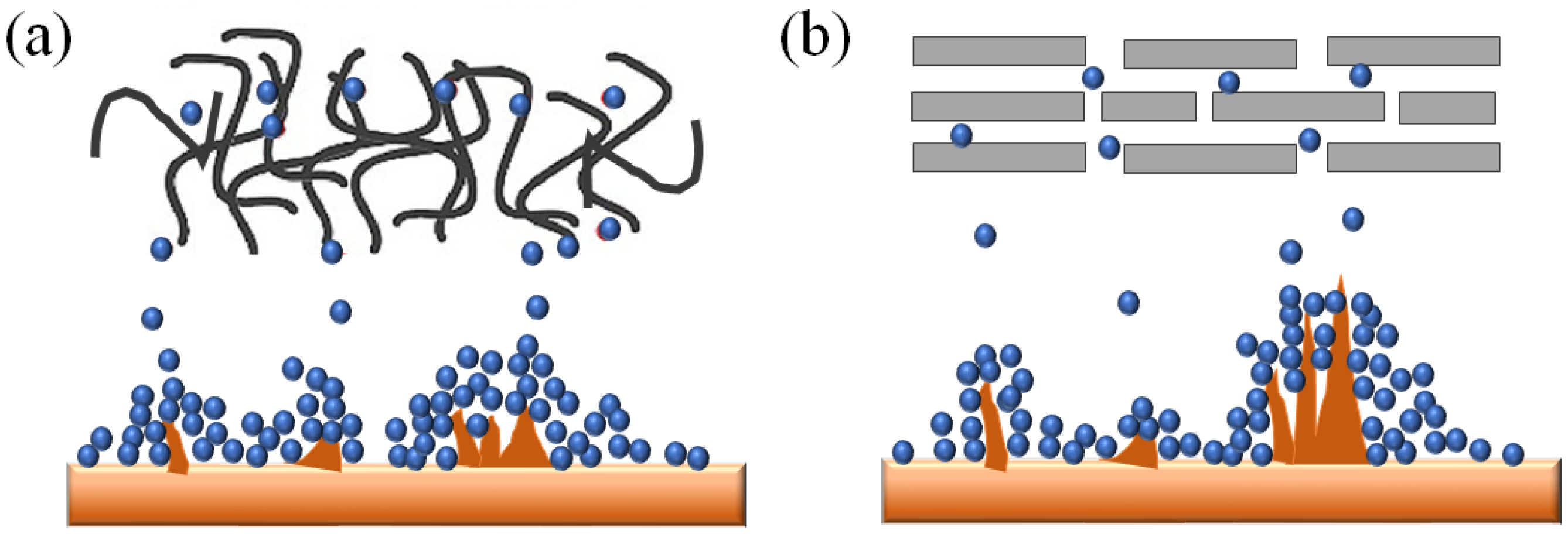
Non-woven membranes are formed by solidifying randomly distributed fibers, and the gaps between the fibers constitute the pore structure of the non-woven fabric, which has a higher porosity compared to polyolefin separators, as shown in Figure 14. However, the weak physical forces between the fibers allow lithium dendrites to easily penetrate the separator and cause a short circuit. In addition, thermal shrinkage at high temperatures is also a major cause of thermal failure. Therefore, attention needs to be paid to the tensile strength and thermal shrinkage rate of non-woven membranes.

4.2.2. Path to Elevate Thermal Stability

The tensile strength of non-woven membranes is affected by multiple factors, including crystallinity, polymer alignment orientation, and physical forces among fibers [136]. The methods to improve its tensile strength mainly include changing the electrospinning process parameters, improving the chain orientation and crystal structure of the polymer in the fiber, and post-treatment of the material. The first two involve complex pretreatment processes, which are not within the scope of this article. The latter provides a simple and efficient way to improve. The main means to improve the thermal dimensional stability of non-woven membranes are no different from the above, mainly divided into surface adhesion and the preparation of membranes with a multilayer structure.
  • Post-processing
Post-processing of separators involves refining pre-treated membranes through heat treatment and mechanical compression to meet performance targets. Among them, heat treatment is a common treatment method, which simply melts the separator at a high temperature to form a cross-linked network structure. As more and more fibers adhere, the crystallinity of the non-woven fabric increases, the number of chemical bonds between the polymer chains increases, thereby enhancing the physical forces between the fibers to increase the tensile strength. Kong [137] placed the fluorinated polyimide (FPI) nanofiber membrane in an environment of 300 °C for 15 s of exposure. Compared with the untreated FPI, the tensile strength increased from 6.8 MPa to 31.7 MPa. Compared with commercial PE, the heat-treated FPI has a higher melting point and a lower thermal shrinkage rate, Tang [138] prepared the aramid nanofiber (ANF) separator using electrospinning. After heat treatment, the tensile strength reached 41.52 MPa, and there was no thermal shrinkage even after exposure at 200 °C for 1 h. The above shows that heat treatment can effectively improve the mechanical stability of non-woven membranes.
Mechanical compression complements heat treatment in separator post-processing by reinforcing fiber-to-fiber adhesion in non-woven architectures. Jiang [139] demonstrated that progressive compression (1–5 MPa) enhances PI separator tensile strength by 300% through reduced inter-fiber voids. Ma [140] found that the diameter and porosity of the non-woven fabric fibers are crucial to the performance of the separator. After the 200 nm diameter PAN-S-H film was compressed under high pressure at 100 °C, the tensile strength was significantly better than other comparison separators and it has higher thermal stability compared to commercial PP.
In summary, post-processing is a simple and efficient improvement method. Both heat treatment and mechanical compression can significantly improve the mechanical properties and thermal stability of the separator. In addition to the above two, there is also the alkali dissolution method [141,142], which is to treat the non-woven membrane in an alkaline solution. Although this method can bring great advantages to the mechanical properties and thermal stability of non-woven membranes, as an emerging technology, it has not yet aroused widespread interest and will be the main direction of research in the future.
2.
Surface coating
Surface adhesion modification represents a widely adopted strategy for enhancing non-woven membrane performance through interfacial reinforcement. The adhered materials are mainly inorganic and polymers, including Al2O3, SiO2, PDA, PEO, PANI, etc. Different from microporous separators, by immersing the non-woven membrane in a coating solution, the coating particles are adhered to the fiber surface to increase the connection points between the fibers. Song et al. [136] prepared the non-woven membrane of PAN, PAN/PEI, and PDA@PAN/PEI possessing the structure of countless nodes between the fibers. This structure increases the tensile strength of the separator by ten times, but the melting temperature is slightly reduced. He’s team [143] used PAALi as a coating material to increase the tensile strength of PI to 16.1 MPa.
Inorganic-polymer hybrid coatings are strategically employed to simultaneously enhance the thermal stability and tensile strength of the separator. Zhang et al. [144] first proposed to introduce silica and sodium alginate into polysulfonamide and use it as a separator for LIBs. It is observed that silica nanoparticles bonded by sodium alginate filled the gaps between the fibers, effectively enhancing the mechanical strength and thermal stability of the separator. Nowadays, to further improve the stability of non-woven membranes, researchers have introduced bionics into it. Du and his colleagues proposed a nest-like network structure SiO2/PVdF-HFP separator; this separator can isolate the inside (cathode) and outside (anode) like a bird’s nest; it is believed that more bionic structures will be introduced into the battery in the future.
3.
Multilayer separator
Multilayer separators refer to separators formed by overlapping multiple fiber materials in order. Different from the late-stage adhesion of immersion, multilayer separators are woven together with multiple layers of fibers based on the characteristics of electrospinning in the early stage of preparation. This method can combine the advantages of different fiber materials and easily manufacture separators that meet various needs. In the research [145], to make up for the poor mechanical stability of the PU film, the high-strength poly(m-phenylene isophthalamide)(PMIA) is woven together. They found that as the content of PMIA increases, the tensile strength of the PMIA-PU separator gradually increases; it was found that after introducing PVdF-HFP into PAN, the thermal stability significantly increased [146].
Table 5 provides the mechanical properties and thermal stability of different fiber materials after spinning. To address mechanical performance deficiencies, high-strength fibers including PMIA, PP, PVdF, PAN, and PET are widely adopted for separator reinforcement. For thermal stability, fiber materials with good thermal stability or thermal switch characteristics such as PET, PVC, and PVdF are commonly used.
Overall, separators can melt, shrink, and perforate when overheated, which can cause the battery to short-circuit and release large amounts of heat. Strategies such as high temperature resistance (non-woven membrane), flame retardancy (composite membrane, non-woven membrane) and increasing porosity (microporous membrane) can be used to improve the thermal stability of the membrane. Although various methods have been used to improve the thermal stability of separators, there are still some issues and challenges, such as how to improve the heat resistance and flame retardancy of separators without sacrificing battery performance. Future research may focus on developing new separator materials and structures to further improve the thermal safety performance of lithium-ion batteries.

5. Electrolyte

5.1. Liquid Electrolyte

Since the introduction of liquid electrolytes, research and discussion on their safety have never stopped. However, most research prioritizes the interface stability between the liquid electrolyte and the electrode, with less emphasis on the liquid electrolyte’s thermal stability. As an important component of LIBs, it is the main factor limiting the working temperature of LIBs. Traditional liquid electrolytes mainly include the following: coordination phosphates (LiPF6 and its derivatives)—this type of electrolyte has good oxidation resistance and high ion conductivity, but it is extremely sensitive to water, and is currently the most widely used LIB electrolyte; coordination borates (LiBF4 and its derivatives)—this type of electrolyte has better thermal stability than coordination phosphates, but the production cost is high and it has not been widely used; sulfonimide salts (LiN(SO2CF3)2 and its derivatives)—this type of electrolyte has good oxidation resistance and thermal stability, but it is easy to corrode the positive current collector; electrolytes containing As—this type of electrolyte has strong oxidizing properties and is prone to side reactions at higher voltages, causing the battery to swell and cause safety problems.
In this article, we will elaborate on the thermal failure process of the common electrolyte LiPF6 and introduce the current methods and strategies to improve the thermal stability of the liquid electrolyte itself.

5.1.1. Thermal Failure Mechanism

Taking the commercial 1 M LiPF6-EC:DEC:DMC 1:1:1 as an example, LiPF6 will decompose to produce PF5 at 200 °C, as shown in the equation, and the remaining part will be oxidized by the oxygen released by the electrode decomposition [161], and the specific oxidation process is as follows:
EC: 2.5O2 + C3H4O3 → 3CO2 + 2H2O
DEC: 6O2 + C5H10O3 → 5CO2 + 5H2O
DMC: 3O2 + C3H6O3(EC) → 3CO2 + 3H2O
PC: 4O2 + C4H6O3(EC) → 4CO2 + 3H2O
The above process releases heat and a large amount of CO2 gas, posing a serious threat to battery safety. Therefore, it is necessary to design a reasonable electrolyte to reduce the risk of thermal runaway.

5.1.2. Path to Elevate Thermal Stability

From the thermal failure process of LiPF6, it can be found that high-temperature decomposition and oxidation are the main reasons for the release of a large amount of heat. Therefore, we can improve the thermal stability of the liquid electrolyte of LIBs from three aspects: inhibiting decomposition, reducing oxygen release, and preventing combustion. Among them, oxygen release occurs on the electrode surface. The generation of active oxygen on the electrode surface has been inhibited by the electrolyte additive in the above discussion, so it will not be repeated here.
  • Inhibit the decomposition of the electrolyte
The decomposition of LiPF6 is primarily attributed to the breakdown of PF6 when it binds with Li+. Trimethyl phosphate (P(OCH3)3) and trimethyl borate (TMB) can inhibit the decomposition of LiPF6 and slow down the dissolution of metals on the cathode surface [162]. However, inhibiting decomposition does not completely eliminate it. Given that even a small amount of decomposition can trigger thermal runaway, it is essential to remove the decomposition products. Effective measures include the following: First, the phosphorus (P) atom in TTFP can donate electrons to capture PF5, while the nitrogen (N) atom in HFEPN also exhibits strong electron-donating ability to trap PF5 [163]. These additives effectively prevent the hydrolysis of the captured PF5, thereby reducing the generation of HF. Second, to remove residual HF in liquid electrolytes, additives such as lithium bis(oxalato)borate (LiBOB), trimethoxyboroxine (TMBX), and other HF scavengers have been proposed [164].
2.
Preventing electrolyte burning
Electrolyte organic solvents generate combustible HO·/H· radicals during thermal runaway, triggering chain reactions [9]. Capturing these radicals with phosphides/fluorides interrupts combustion chains, achieving flame retardancy.
Trimethyl phosphate (TMP) is the earliest and most widely studied flame retardant in phosphides. TMP has a simple structure and easily decomposes into PO2· and HPO2· at high temperatures. These free radicals easily combine with H to prevent combustion reactions [165]. TMP exhibits strong antioxidative but weak anti-reduction properties, compromising battery performance. While triethyl phosphate (TEP) offers better reduction resistance, its lower phosphorus content reduces flame retardancy compared to TMP. Combining both additives balances these properties but decreases electrolyte ionic conductivity. To address this, phenyl-substituted phosphates have been developed to simultaneously enhance flame retardancy and reduction stability. The dibenzyl octyl phosphate (DPOF) flame retardant increased the decomposition temperature of the electrolyte by 7.4% and the Coulomb efficiency by 1.2% [166].
Halogen flame retardants are widely used in consumer goods, textiles, and electronic products to reduce the risk of fire. The flame-retardant mechanism is shown in the following formula:
RX → R·+ X·
X·+ H → HX
HX + HO· → H2O + X
X·+ HR → HX + R
Among them, chlorine-based flame retardants are cheap, but their thermal stability is poor, bromine-based flame retardants have high flame retardant efficiency, but they are harmful to the environment and have been banned in many countries, fluorine-based flame retardants have high flash points and good thermal stability, and are commonly used in LIB electrolytes, including 1,3,5-trifluorobenzene(F3B), difluoroalkyl carbonates (DACs) and ethoxy(pentafluoro) cyclotriphosphazene (PFPN), etc. However, Equation (4) shows that fluorine-based flame retardants will generate HF gas, which may cause more serious safety accidents. Therefore, halogen flame retardants will develop in the direction of green and degradable in the future.

5.2. Solid Electrolyte

The solid electrolyte (SE) is an ideal electrolyte material, which has advantages such as high energy density, fast charging, long life, and high safety, and has obvious advantages compared to liquid electrolyte. Solid electrolytes can be divided into three categories according to their main components: inorganic solid electrolytes, solid polymer electrolytes, and composite solid electrolytes. These three types of solid electrolytes each have their applicable fields and characteristics, but there are also some common challenges, the most important of which is the issue of thermal stability. Although the SE is considered a thermally safe electrolyte due to its flame-retardant characteristics, under high-temperature conditions, the SE will still decompose, causing the risk of short circuits and thermal runaway inside the battery. Therefore, this article will analyze the causes of its thermal failure from the two aspects of the SE’s decomposition temperature and decomposition mechanism, and propose some possible improvement methods to improve the thermal stability of the SE.

5.2.1. Thermal Failure Mechanism

The thermal failure mechanism of the SE mainly includes two aspects: one is the interfacial chemical reaction between the SE and electrode materials, and the other is the intrinsic decomposition reaction of the SE.
The interfacial chemical reaction refers to a series of redox reactions that occur after the electrode material encounters the electrolyte, which results in the formation of some new compounds.
These reactions will generate a certain amount of heat, but not enough to cause thermal runaway. The intrinsic decomposition reaction refers to the SE at high temperatures; due to its structural and compositional instability, its own decomposition reaction occurs, releasing oxygen and other gases. These gases will further react with the electrode, generating a large amount of heat, leading to the occurrence of thermal runaway. In addition, interfacial thermal resistance is a major factor contributing to thermal runaway. The interface primarily arises from incomplete contact between the solid electrolyte and the electrode material, as well as the presence of voids and gas layers at the contact interface. These factors hinder heat transfer at the interface, thereby affecting the overall heat dissipation performance of the battery. The distinct thermal failure behaviors of different solid electrolytes stem primarily from their unique structural and compositional characteristics.
  • Inorganic solid electrolyte
Inorganic solid electrolytes predominantly consist of oxides and sulfides. Among oxide electrolytes, garnet-type Li5La3Zr2O12 (LLZO) features edge-sharing ZrO6 octahedra (Figure 15a), which enhance high-temperature stability by suppressing oxygen release [167]. However, the air sensitivity of LLZO makes this structure no longer stable. The perovskite solid electrolyte mainly composed of Li3xLa0.67−xTiO3 (LLTO) and the solid electrolyte with the general formula LiM2(PO4)3 (M = Al, Ge, Zr) are composed of a shared-vertex TiO6 octahedron [168] (Figure 15b) and PO4 tetrahedron [169] (Figure 15c). Compared with LLZO, the thermal stability has decreased, and metal ions such as Ti4+ are prone to reduction reactions, which can destroy the crystal structure and even form lithium dendrites.
Due to various problems with oxides, researchers have turned their attention to sulfide electrolytes with higher conductivity. However, sulfide electrolytes are not more stable compared to oxide electrolytes. In glassy Li2S-P2S5 sulfide electrolytes, amorphous Li3PS4 is stable at low temperatures (Figure 15d), but transforms to high-symmetry α-Li3PS4 above ~420 °C, reducing thermal stability [170]. The ceramic crystal sulfide electrolyte mainly composed of Li10GeP2S12 (LGPS) usually has a crystal structure of a three-dimensional network composed of tetrahedra and octahedra [171], as shown in Figure 15e. This structure not only provides more ion channels, but also plays a good supporting role. However, LGPS has a very serious interface problem with the lithium metal anode, which is also mentioned in the ‘Lithium Metal Composite’ section, which will cause a very serious decline in battery performance and safety risks. In addition, regardless of the type of sulfide electrolyte, the bulging phenomenon caused by the generation of H2S gas is observed during the battery cycle.
2.
Solid polymer electrolyte
The solid polymer electrolyte (SPE) has received widespread attention due to its excellent stretchability, chemical inertness, and good compatibility with electrodes [172]. However, the stability of the SPE at high temperatures still causes issues. As the temperature rises, the chain segment motion in the SPE becomes faster and faster, the SPE has difficulty in maintaining its structural form and gradually shrinks, eventually leading to direct contact between the cathode and anode and causing a short circuit [173]. What is more serious is that when the temperature continues to rise, the chain structure in the SPE begins to break, and individual polymer monomers are separated from the SPE. These polymer monomers will further burn and cause more serious thermal runaway [11].
3.
Other solid electrolytes
In addition to the above-mentioned common SEs, halide SEs and hydride SEs have also attracted some researchers’ attention. Halides usually have good thermal stability and can maintain a complete structure above 300 °C [174]. However, its conductivity can only show better values in high-temperature environments, and the lower conductivity in room temperature environments limits its widespread application. The hydride solid electrolyte has a high ion conductivity at the same level as the liquid electrolyte, but its thermal stability is extremely poor, and it is easy to generate flammable and explosive hydrogen gas at high temperatures. Therefore, hydride solid electrolytes are often used in fields such as energy storage that have stable environments and perfect safety protection measures [175].

5.2.2. Path to Elevate Thermal Stability

  • Element doping
Element doping represents the most straightforward approach to bolstering the stability of crystal phase structures, as the incorporation of doped metal elements can substitute for certain lattice sites, thereby reinforcing the overall stability of the lattice framework. Among solid electrolytes, oxides stand out for their superior thermal stability, attributable to their inherent structural benefits [10]. For instance, the decomposition temperature of LLZO (a lithium-containing garnet oxide) soars to as high as 1000 °C, while LATP (another lithium-ion conducting oxide) exhibits an even higher decomposition temperature of 1121 °C [176]. Consequently, doping strategies in oxide solid electrolytes (SEs) primarily aim to enhance lithium-ion diffusion rates, thereby mitigating the growth of lithium dendrites. Specifically, when Ta5+ is employed to replace Zr4+ within the crystal structure, it not only preserves the crystal phase stability but also generates additional lithium vacancies. These vacancies facilitate efficient lithium-ion conduction, effectively preventing the formation of lithium dendrites [177].
However, it is noteworthy that most of the existing research has primarily focused on improving lithium-ion diffusion rates to curb dendrite growth, with relatively limited attention paid to the air sensitivity of LLZO. Addressing this gap, Luo’s research team [178] undertook a study where they co-doped Ga and Y into LLZO and subsequently evaluated its chemical stability. Their findings revealed that the co-doped LLZO demonstrated remarkable chemical inertness when exposed to air and could maintain its structural integrity even at temperatures exceeding 900 °C.
To solve the problem of the decrease in thermal stability caused by the transition of Li3PS4 from the β phase to the α phase at high temperatures, Si is introduced into Li3PS4 [170], and the newly synthesized Li3.25Si0.25P0.75S4 can also maintain the β phase at 600 °C. Not only that, Sn and Ge are also considered to effectively improve the thermal stability of sulfide solid electrolytes. For example, the melting point of Li2SnS3 is as high as 750 °C, the melting points of Li4SnS4 and Li4GeS4 are as high as 858 °C and 958 °C, respectively, and Li10SnP2S12 only shows obvious thermal shrinkage when heated above 900 °C [179].
2.
Composite solid electrolyte
In addition to element doping, the addition of compounds to solid electrolytes to form composite solid electrolytes can also effectively improve thermal stability. For instance, the air stability of Li3PS4 (LPS) is enhanced by incorporating ZnO, while LPS-ZnO thermal stability decreases with increasing ZnO content, with 10–20 mol% achieving the optimal balance between thermal and chemical stability. Subsequent studies by the same team demonstrated that adding 10 mol% Li2O to Li2S-P2S5 simultaneously improved thermal and air stability. Calpa and his colleagues [180] significantly reduced the production of H2S gas and significantly improved the stability of Li3PS4 in the air by introducing LiI into Li3PS4.
Composite solid electrolytes enhance solid polymer electrolytes by blending thermally stable, mechanically robust materials with polymers to achieve high safety. Thus, multi-polymer blending is commonly employed to balance electrolyte performance. The PAN-PVC-LiTFSI polymer electrolyte not only has excellent thermal stability (315 °C), but also solves the problem of low Coulomb efficiency caused by the high polarity of PAN [181]. However, the above research shows that reducing the impact of PAN’s high polarity is a complex process. PVDF’s excellent thermal stability and high dielectric constant provide another way to improve polymer electrolytes.
3.
Other improvement measures
To enhance polymer electrolyte thermal stability, researchers employ three strategies: (1) modifying the chain architecture via grafting/blocking/crosslinking to improve thermomechanical properties and ionic conductivity; (2) introducing plasticizers/ionic liquids to increase the dielectric constant and suppress crystallization; (3) constructing fluoride/nitride/carbide interface layers to mitigate electrode side reactions and inhibit lithium dendrite growth, thereby improving cycle stability and safety. In addition to material modification, researchers also adjust the polymer chain/crystallinity and change the lattice structure through heat treatment, which helps to improve conductivity, thermal stability, and tensile strength [182]. Furthermore, for the reduction in the interfacial thermal resistance, measures such as interfacial modification, three-dimensional structural design, and gradient structural design are mainly employed to reduce the interfacial thermal resistance of solid electrolytes[183].
In general, because solid electrolytes have a higher thermal stability than liquid electrolytes, research on solid electrolytes mainly focuses on conductivity, and there is a lack of systematic research and experimental research on its thermal stability. However, with the development of LIBs, we believe that researchers will pay more and more attention to the thermal stability of solid electrolytes in the future. Table 6 lists the studies on the thermal stability of different electrolytes using different methods.
To sum up, the electrolyte is prone to decomposition under extreme conditions such as high temperature, overcharge, and over-discharge, generating heat and gas, which may lead to the thermal runaway of the battery. Thermal stability and safety of batteries can be improved by using non-flammable solvents or solid electrolytes. Adding flame retardant additives, such as phosphorus compounds, to the electrolyte can slow down the decomposition rate of the electrolyte and improve thermal stability. The research and development of new electrolytes, such as polymer-based solid electrolytes, can structurally improve the thermal stability of electrolytes.

6. Conclusions and Future Outlook

Manufacturing safe and stable LIBs is an age-old goal, but the safety of LIBs is affected by the internal components. In this article, we discuss in detail the thermal runaway mechanisms of the current LIB components and the corresponding improvement measures.
(1)
In the positive electrode of LIBs, the thermal runaway mechanism is explained from the perspective of structural evolution and chemical reactions, providing a theoretical basis for enhancing the stability of the cathode material. The focus is on strategies to improve thermal stability, such as doping, coating, and structural optimization. However, these strategies still face some challenges. For example, the mechanism of cation mixing caused by element doping, the formation and evolution mechanism of CEI due to adhesion, and the difficulty of the single crystallization of cathode materials are not clear. Therefore, it is necessary to conduct more systematic and in-depth research on these mechanisms and develop excellent synthesis methods.
(2)
In the negative electrode of LIBs, the article discusses the thermal characteristics of different negative electrode materials and finds that the thermal stability of negative electrode materials is also an important factor affecting the safety of LIBs, especially in the case of overcharging or short circuits. The commonly used anode materials include graphite, silicon, lithium metal, etc., each of which has different thermal behaviors and thermal failure mechanisms, such as the oxidation of graphite, the expansion of silicon, and the dendritic growth of lithium metal. In addition, the improvements involve surface coatings, doping, and the use of composite materials to enhance thermal stability. Therefore, we believe that the future research focus should be to develop high-capacity, high thermal stability, low-expansion new anode materials, such as silicon/carbon composites, lithium metal, lithium sulfides, etc., and optimize the structure, morphology, composition, etc., of the anode to improve its thermal safety performance.
(3)
In the separator of LIBs, the article reviews the thermal characteristics of the separator. The separator is a key component in LIBs, which serves to isolate the positive and negative electrodes, conduct lithium ions, and prevent thermal runaway. Commonly used separator materials include polypropylene, polyethylene, etc., which have higher melting points and lower thermal shrinkage rates and can resist thermal shock to a certain extent. However, there are also some defects in the separator materials, such as low porosity, poor mechanical strength, and decreased thermal stability over time. The strategies include increasing tensile strength, reducing thermal shrinkage, and developing multilayer structures. Therefore, we believe that future research should aim to develop new separator materials with high thermal stability, high mechanical strength, and high ion conductivity, such as ceramic composite separators, polymer nanofiber separators, porous metal separators, etc., and optimize the structure, morphology, and composition of the separator to improve its thermal safety performance.
(4)
In the electrolyte of LIBs, the article briefly introduces the thermal characteristics of the electrolyte, pointing out that the decomposition and reaction of the electrolyte are among the main causes of thermal runaway in LIBs, especially under high temperature and high voltage conditions. Currently, the approaches focus on additives to improve thermal stability and the development of solid electrolytes with higher decomposition temperatures. Hence, we posit that future research should concentrate on the development of novel electrolyte materials characterized by superior thermal, electrochemical stability, and high ion conductivity, such as ionic liquids, solid electrolytes, polymer electrolytes, etc., and on optimizing the structure, morphology, and composition of the electrolyte to improve its thermal safety performance.
In addition, we found that some strategies to improve the thermal stability of lithium-ion batteries can also slow down the aging of lithium-ion batteries, such as improving the structural stability of electrode materials through doping or coating, thereby slowing down battery aging. This can be conducted through the use additives or developing new electrolytes to improve their thermal and chemical stability. However, the current strategies and technologies still have the following limitations: For example, (1) in the improvement of electrodes materials, surface coating technology faces challenges in achieving uniformity and precise thickness control, while the development of novel high-stability materials is constrained by cost and lengthy development cycles, making rapid large-scale application difficult. (2) For electrolyte improvement, flame-retardant additives may compromise electrochemical performance, and solid electrolytes, due to their high interfacial resistance and poor compatibility, undermine the reliability of practical applications. (3) Regarding separator improvement, although ceramic coatings enhance performance, they reduce ionic conductivity.
Based on the above research, we give several common rules for designing lithium-ion battery components to enhance thermal stability and mitigate aging: Introducing different elements into the crystal lattice improves the thermal stability and lifespan of electrode material and applying coatings to electrode materials can mitigate boundary reactions and structural changes that lead to thermal failure. Adjusting the structure of materials, such as creating core–shell or polycrystalline structures, can enhance thermal stability and lifespan, and prevent thermal runaway. Utilizing solid electrolytes instead of liquid ones can improve safety by reducing flammability and enhancing thermal stability. These strategies collectively contribute to the overall thermal safety performance of lithium-ion batteries.

Author Contributions

Conceptualization, A.Y. and J.F.; methodology, J.P.; software, J.F.; validation, J.P., J.F. and A.Y.; formal analysis, J.P.; investigation, J.F.; data curation, J.P.; writing—original draft preparation, J.F.; writing—review and editing, A.Y.; visualization, J.P.; project administration, A.Y.; funding acquisition, A.Y. All authors have read and agreed to the published version of the manuscript.

Funding

This research is funded by the Natural Science Research Key Project of Colleges and Universities of Anhui Province (2024AH051398), the China Postdoctoral Science Foundation (2022M721618), Chuzhou University Research Start-up Fund Project (2024qd29). They are gratefully acknowledged.

Data Availability Statement

The original contributions presented in the study are included in the article; further inquiries can be directed to the corresponding author.

Conflicts of Interest

Author Jinjie Feng was employed by the Sinopec Guangzhou Engineering Co., Ltd. The remaining authors declare that the research was conducted in the absence of any commercial or financial relationships that could be construed as a potential conflict of interest.

References

  1. Feng, X.; Ren, D.; He, X.; Ouyang, M. Mitigating thermal runaway of lithium-ion batteries. Joule 2020, 4, 743–770. [Google Scholar] [CrossRef]
  2. He, W.; Guo, W.; Wu, H.; Lin, L.; Liu, Q.; Han, X.; Xie, Q.; Liu, P.; Zheng, H.; Wang, L.; et al. Challenges and recent advances in high capacity Li-rich cathode materials for high energy density lithium-ion batteries. Adv. Mater. 2021, 33, 2005937. [Google Scholar] [CrossRef]
  3. Iskandar Radzi, Z.; Helmy Arifin, K.; Zieauddin Kufian, M.; Balakrishnan, V.; Rohani Sheikh Raihan, S.; Abd Rahim, N.; Subramaniam, R. Review of spinel LiMn2O4 cathode materials under high cut-off voltage in lithium-ion batteries: Challenges and strategies. J. Electroanal. Chem. 2022, 920, 116623. [Google Scholar] [CrossRef]
  4. Wang, L.; Zhou, Z.; Yan, X.; Hou, F.; Wen, L.; Luo, W.; Liang, J.; Dou, S.X. Engineering of lithium-metal anodes towards a safe and stable battery. Energy Storage Mater. 2018, 14, 22–48. [Google Scholar] [CrossRef]
  5. Wang, R.; Cui, W.; Chu, F.; Wu, F. Lithium metal anodes: Present and future. J. Energy Chem. 2020, 48, 145–159. [Google Scholar] [CrossRef]
  6. Yang, X.; Peng, Y.; Hou, J.; Liu, Y.; Jian, X. A review for modified Li composite anode: Principle, preparation and challenge. Nanotechnol. Rev. 2020, 9, 1610–1624. [Google Scholar] [CrossRef]
  7. Dai, X.; Zhang, X.; Wen, J.; Wang, C.; Ma, X.; Yang, Y.; Huang, G.; Ye, H.; Xu, S. Research progress on high-temperature resistant polymer separators for lithium-ion batteries. Energy Storage Mater. 2022, 51, 638–659. [Google Scholar] [CrossRef]
  8. Thakur, A.K.; Kumar, A.; Park, H.; Kim, H.; Ahmed, M.S.; Saleque, A.M.; Vikram, M.P.; Saidur, R.; Ma, Y.; Hwang, J.-Y. Composite separators for internal thermal management in rechargeable lithium batteries: A review. J. Energy Storage 2023, 73, 108873. [Google Scholar] [CrossRef]
  9. Zhang, S.; Li, S.; Lu, Y. Designing safer lithium-based batteries with nonflammable electrolytes: A review. eScience 2021, 1, 163–177. [Google Scholar] [CrossRef]
  10. Manthiram, A.; Yu, X.; Wang, S. Lithium battery chemistries enabled by solid-state electrolytes. Nat. Rev. Mater. 2017, 2, 16103. [Google Scholar] [CrossRef]
  11. Chen, M.; Yue, Z.; Wu, Y.; Wang, Y.; Li, Y.; Chen, Z. Thermal stable polymer-based solid electrolytes: Design strategies and corresponding stable mechanisms for solid-state Li metal batteries. Sustain. Mater. Technol. 2023, 36, e00587. [Google Scholar] [CrossRef]
  12. Jiang, M.; Danilov, D.L.; Eichel, R.A.; Notten, P.H.L. A review of degradation mechanisms and recent achievements for Ni-rich cathode-based Li-ion batteries. Adv. Energy Mater. 2021, 11, 2103005. [Google Scholar] [CrossRef]
  13. Lin, F.; Markus, I.M.; Nordlund, D.; Weng, T.-C.; Asta, M.D.; Xin, H.L.; Doeff, M.M. Surface reconstruction and chemical evolution of stoichiometric layered cathode materials for lithium-ion batteries. Nat. Commun. 2014, 5, 3529. [Google Scholar] [CrossRef] [PubMed]
  14. Whittingham, M.S. Lithium batteries and cathode materials. Chem. Rev. 2004, 104, 4271–4302. [Google Scholar] [CrossRef] [PubMed]
  15. Manthiram, A.; Song, B.; Li, W. A perspective on nickel-rich layered oxide cathodes for lithium-ion batteries. Energy Storage Mater. 2017, 6, 125–139. [Google Scholar] [CrossRef]
  16. Manthiram, A.; Murugan, A.V.; Sarkar, A.; Muraliganth, T. Nanostructured electrode materials for electrochemical energy storage and conversion. Energy Environ. Sci. 2008, 1, 621–638. [Google Scholar] [CrossRef]
  17. Gao, A.; Sun, Y.; Zhang, Q.; Zheng, J.; Lu, X. Evolution of Ni/Li antisites under the phase transition of a layered LiNi1/3Co1/3Mn1/3O2 cathode. J. Mater. Chem. A 2020, 8, 6337–6348. [Google Scholar] [CrossRef]
  18. Bak, S.-M.; Hu, E.; Zhou, Y.; Yu, X.; Senanayake, S.D.; Cho, S.-J.; Kim, K.-B.; Chung, K.Y.; Yang, X.-Q.; Nam, K.-W. Structural changes and thermal stability of charged LiNixMnyCozO2 cathode materials studied by combined in situ time-resolved XRD and mass spectroscopy. ACS Appl. Mater. Interfaces 2014, 6, 22594–22601. [Google Scholar] [CrossRef]
  19. Kanamori, J. Superexchange interaction and symmetry properties of electron orbitals. J. Phys. Chem. Solids 1959, 10, 87–98. [Google Scholar] [CrossRef]
  20. Manthiram, A.; Knight, J.C.; Myung, S.T.; Oh, S.M.; Sun, Y.K. Nickel-rich and lithium-rich layered oxide cathodes: Progress and perspectives. Adv. Energy Mater. 2016, 6, 1501010. [Google Scholar] [CrossRef]
  21. Li, W.; Dolocan, A.; Oh, P.; Celio, H.; Park, S.; Cho, J.; Manthiram, A. Dynamic behaviour of interphases and its implication on high-energy-density cathode materials in lithium-ion batteries. Nat. Commun. 2017, 8, 14589. [Google Scholar] [CrossRef]
  22. Guo, B.; Zhao, J.; Fan, X.; Zhang, W.; Li, S.; Yang, Z.; Chen, Z.; Zhang, W. Aluminum and fluorine co-doping for promotion of stability and safety of lithium-rich layered cathode material. Electrochim. Acta 2017, 236, 171–179. [Google Scholar] [CrossRef]
  23. Zhang, M.; Zhao, H.; Tan, M.; Liu, J.; Hu, Y.; Liu, S.; Shu, X.; Li, H.; Ran, Q.; Cai, J.; et al. Yttrium modified Ni-rich LiNi0.8Co0.1Mn0.1O2 with enhanced electrochemical performance as high energy density cathode material at 4.5 V high voltage. J. Alloys Compd. 2019, 774, 82–92. [Google Scholar] [CrossRef]
  24. Huang, C.; Wang, Z.; Wang, H.; Huang, D.; He, Y.; Zhao, S. Mg2+ doping into Li sites to improve anionic redox reversibility and thermal stability of lithium-rich manganese-based oxides cathode. J. Mater. Today Energy 2022, 29, 101116. [Google Scholar] [CrossRef]
  25. Shen, Y.; Yao, X.; Zhang, J.; Wang, S.; Zhang, D.; Yin, D.; Wang, L.; Zhang, Y.; Hu, J.; Cheng, Y.; et al. Sodium doping derived electromagnetic center of lithium layered oxide cathode materials with enhanced lithium storage. Nano Energy 2022, 94, 106900. [Google Scholar] [CrossRef]
  26. Liu, L.; Su, G.; Xiao, Q.; Ding, Y.; Wang, C.; Gao, D. Structural, electrochemical and thermal properties of LiNi0.8−xCo0.2CexO2 as cathode materials for lithium ion batteries. Mater. Chem. Phys. 2006, 100, 236–240. [Google Scholar] [CrossRef]
  27. Liu, H.; Li, J.; Zhang, Z.; Gong, Z.; Yang, Y. Structural, electrochemical and thermal properties of LiNi0. 8−yTiyCo0.2O2 as cathode materials for lithium ion battery. Electrochim. Acta 2004, 49, 1151–1159. [Google Scholar] [CrossRef]
  28. Kim, U.-H.; Jun, D.-W.; Park, K.-J.; Zhang, Q.; Kaghazchi, P.; Aurbach, D.; Major, D.T.; Goobes, G.; Dixit, M.; Leifer, N. Pushing the limit of layered transition metal oxide cathodes for high-energy density rechargeable Li ion batteries. Energy Environ. Sci. 2018, 11, 1271–1279. [Google Scholar] [CrossRef]
  29. D’Epifanio, A.; Croce, F.; Ronci, F.; Rossi Albertini, V.; Traversa, E.; Scrosati, B. Effect of Mg2+ doping on the structural, thermal, and electrochemical properties of LiNi0.8Co0.16Mg0.04O2. Chem. Mater. 2004, 16, 3559–3564. [Google Scholar] [CrossRef]
  30. Bang, H.J.; Park, B.-C.; Prakash, J.; Sun, Y.-K. Synthesis and electrochemical properties of Li [Ni0.45Co0.1Mn0.45−xZrx]O2 (x=0, 0.02) via co-precipitation method. J. Power Sources 2007, 174, 565–568. [Google Scholar] [CrossRef]
  31. Cho, W.; Song, J.H.; Lee, K.-W.; Lee, M.-W.; Kim, H.; Yu, J.-S.; Kim, Y.-J.; Kim, K.J. Improved particle hardness of Ti-doped LiNi1/3Co1/3Mn1/3-xTixO2 as high-voltage cathode material for lithium-ion batteries. J. Phys. Chem. Solids 2018, 123, 271–278. [Google Scholar] [CrossRef]
  32. Luo, W.; Li, X.; Dahn, J.R. Synthesis, characterization, and thermal stability of Li[Ni1/3Mn1/3Co1/3−z(MnMg)z/2]O2. Chem. Mater. 2010, 22, 5065–5073. [Google Scholar] [CrossRef]
  33. Levartovsky, Y.; Chakraborty, A.; Kunnikuruvan, S.; Maiti, S.; Grinblat, J.; Talianker, M.; Major, D.T.; Aurbach, D. Enhancement of structural, electrochemical, and thermal properties of high-energy density Ni-rich LiNi0.85Co0.1Mn0.05O2 cathode materials for Li-ion batteries by niobium doping. ACS Appl. Mater. Interfaces 2021, 13, 34145–34156. [Google Scholar] [CrossRef] [PubMed]
  34. Lipson, A.L.; Durham, J.L.; LeResche, M.; Abu-Baker, I.; Murphy, M.J.; Fister, T.T.; Wang, L.; Zhou, F.; Liu, L.; Kim, K.; et al. Improving the thermal stability of NMC622 Li-ion battery cathodes through doping during coprecipitation. ACS Appl. Mater. Interfaces 2020, 12, 18512–18518. [Google Scholar] [CrossRef] [PubMed]
  35. Zhao, Y.; Lv, Z.; Xu, T.; Li, J. SiO2 coated Li1.2Ni0.2Mn0.6O2 as cathode materials with rate performance, HF scavenging and thermal properties for Li-ion batteries. J. Alloys Compd. 2017, 715, 105–111. [Google Scholar] [CrossRef]
  36. Sun, J.; Zheng, Z.; Xia, W.; Zhou, L.; Wei, Y.; Bei, F. Preparation of CeO2-coated Li1.2Mn0.54Co0.13Ni0.13O2 as cathode materials for lithium ion batteries. Int. J. Electrochem. Sci. 2022, 17, 221265. [Google Scholar] [CrossRef]
  37. Zhu, Y.; Zhang, N.; Zhao, L.; Xu, J.; Liu, Z.; Liu, Y.; Wu, J.; Ding, F. Improving electrochemical performance of lithium-rich cathode material Li1.2Mn0.52Ni0.13Co0.13W0.02O2 coated with Li2WO4 for lithiumion batteries. J. Alloys Compd. 2019, 811, 152023. [Google Scholar] [CrossRef]
  38. Wu, Y.S.; Pham, Q.T.; Yang, C.C.; Chern, C.S.; Musuvadhi Babulal, L.; Seenivasan, M.; Brunklaus, G.; Placke, T.; Hwang, B.J.; Winter, M. Study of electrochemical performance and thermal property of LiNi0.5Co0.2Mn0.3O2 cathode materials coated with a novel oligomer additive for high-safety lithium-ion batteries. Chem. Eng. J. 2021, 405, 126727. [Google Scholar] [CrossRef]
  39. Wang, K.; Mao, Q.; Lu, X.; Zhang, J.; Huang, H.; Gan, Y.; He, X.; Xia, X.; Zhang, W.; Xia, Y. Fluorides coated Ni-rich cathode materials with enhanced surficial chemical stability for advanced lithium-ion battery. Sustain. Mater.Technol. 2023, 38, e00713. [Google Scholar] [CrossRef]
  40. Cho, W.; Lim, Y.J.; Lee, S.; Kim, J.H.; Song, J.; Yu, J.; Kim, Y.; Park, M. Facile Mn surface doping of Ni-rich layered cathode materials for lithium ion batteries. ACS Appl. Mater. Interfaces 2018, 10, 38915–38921. [Google Scholar] [CrossRef]
  41. Cho, W.; Kim, S.; Song, J.H.; Yim, T.; Woo, S.; Lee, K.; Kim, J.; Kim, Y. Improved electrochemical and thermal properties of nickel rich LiNi0.6Co0.2Mn0.2O2 cathode materials by SiO2 coating. J. Power Sources 2015, 282, 45–50. [Google Scholar] [CrossRef]
  42. Chen, Y.; Zhang, Y.; Chen, B.; Wang, Z.; Lu, C. An approach to application for LiNi0.6Co0.2Mn0.2O2 cathode material at high cutoff voltage by TiO2 coating. J. Power Sources 2014, 256, 20–27. [Google Scholar] [CrossRef]
  43. Cho, J.; Kim, T.; Kim, C.; Lee, J.; Kim, Y.; Park, B. Comparison of Al2O3 and AlPO4−coated LiCoO2 cathode materials for a Li-ion cell. J. Power Sources 2005, 146, 58–64. [Google Scholar] [CrossRef]
  44. Park, B.C.; Kim, H.B.; Myung, S.T.; Amine, K.; Belharouak, I.; Lee, S.M.; Sun, Y.K. Improvement of structural and electrochemical properties of AlF3-coated Li[Ni1/3Co1/3Mn1/3]O2 cathode materials on high voltage region. J. Power Sources 2008, 178, 826–831. [Google Scholar] [CrossRef]
  45. Guo, R.; Shi, P.; Cheng, X.; Sun, L. Effect of ZnO modification on the performance of LiNi0.5Co0.25Mn0.25O2 cathode material. Electrochim. Acta 2009, 54, 5796–5803. [Google Scholar] [CrossRef]
  46. Wang, J.; Zhao, X.; Zou, G.; Zhang, L.; Han, S.; Li, Y.; Liu, D.; Fernandez, C.; Li, L.; Ren, L.; et al. Crystal-defect engineering of electrode materials for energy storage and conversion. Mater. Today Nano 2023, 22, 100336. [Google Scholar] [CrossRef]
  47. Zeng, W.; Xia, F.; Tian, W.; Cao, F.; Chen, J.; Wu, J.; Song, R.; Mu, S. Single-crystal high-nickel layered cathodes for lithium-ion batteries: Advantages, mechanism, challenges and approaches. Curr. Opin. Electrochem. 2022, 31, 100831. [Google Scholar] [CrossRef]
  48. Langdon, J.; Manthiram, A. A perspective on single-crystal layered oxide cathodes for lithium-ion batteries. Energy Storage Mater. 2021, 37, 143–160. [Google Scholar] [CrossRef]
  49. Yu, A.; Xi, Y.; Xu, W.; Wang, A.; Liu, L.; Zhang, L. Fabrication and performance evaluation of the flexible positive temperature coefficient material for self-regulating thermal control. J. Appl. Polym. Sci. 2023, 140, e54311. [Google Scholar] [CrossRef]
  50. Feng, J.; Yu, A.; Zhang, L.; Liu, F.; Zhan, Z. Adaptive self-preheating lithium-ion battery system based on positive temperature coefficient material at sub-freezing temperatures. Appl. Therm. Eng. 2025, 278, 127319. [Google Scholar] [CrossRef]
  51. Yu, A.; Li, Q. Temperature-dependent resistivity performance of Mn/Y-doped Ba1-xSrxTiO3 compositions with potential thermal control applications. Ceram. Int. 2020, 46, 8796–8805. [Google Scholar] [CrossRef]
  52. Yu, A.; Li, Q. Studies on preparation and thermal control behavior of hybrid fillers/binary-polymer composites with positive temperature coefficient characteristic. Sci. China Technol. Sci. 2021, 64, 1447–1458. [Google Scholar] [CrossRef]
  53. Wang, D.; Wu, Y.; Wu, C.; Ye, Z.; Yang, L.; Li, Y.; Dong, R.; Wu, Z.; Sun, Y.; Song, Y.; et al. Highly oriented {010} crystal plane induced by boron in cobalt-free Li- and Mn-rich layered oxide. ACS Appl. Mater. Interfaces 2022, 14, 2711–2719. [Google Scholar] [CrossRef]
  54. Cha, H.; Kim, J.; Lee, H.; Kim, N.; Hwang, J.; Sung, J.; Yoon, M.; Kim, K.; Cho, J. Boosting reaction homogeneity in high-energy lithium-ion battery cathode materials. Adv. Mater. 2020, 32, 2003040. [Google Scholar] [CrossRef]
  55. Wei, W.; Ding, Z.; Chen, C.; Yang, C.; Han, B.; Xiao, L.; Liang, C.; Gao, P.; Cho, K. Surface-dependent stress-corrosion cracking in Ni-rich layered oxide cathodes. Acta Mater. 2021, 212, 116914. [Google Scholar] [CrossRef]
  56. Pang, P.; Tan, X.; Wang, Z.; Cai, Z.; Nan, J.; Xing, Z.; Li, H. Crack-free single-crystal LiNi0.83Co0.10Mn0.07O2 as cycling/thermal stable cathode materials for high-voltage lithium-ion batteries. Electrochim. Acta 2021, 365, 137380. [Google Scholar] [CrossRef]
  57. Pan, H.; Jiao, S.; Xue, Z.; Zhang, J.; Xu, X.; Gan, L.; Li, Q.; Liu, Y.; Yu, X.; Li, H.; et al. The roles of Ni and Mn in the thermal stability of lithium-rich manganese-rich oxide cathode. Adv. Energy Mater. 2023, 13, 2203989. [Google Scholar] [CrossRef]
  58. Sun, Y.K.; Myung, S.T.; Kim, M.H.; Prakash, J.; Amine, K. Synthesis and characterization of Li[(Ni0.8Co0.1Mn0.1)0.8(Ni0.5Mn0.5)0.2]O2 with the microscale core−shell structure as the positive electrode material for lithium batteries. J. Am. Chem. Soc. 2005, 127, 13411–13418. [Google Scholar] [CrossRef] [PubMed]
  59. Phillips, P.J.; Bareño, J.; Li, Y.; Abraham, D.P.; Klie, R.F. On the localized nature of the structural transformations of Li2MnO3 following electrochemical cycling. Adv. Energy Mater. 2015, 5, 1501252. [Google Scholar] [CrossRef]
  60. Ben, L.; Yu, H.; Chen, B.; Chen, Y.; Gong, Y.; Yang, X.; Gu, L.; Huang, X. Unusual spinel-to-layered transformation in LiMn2O4 cathode explained by electrochemical and thermal stability investigation. ACS Appl. Mater. Interfaces 2017, 9, 35463–35475. [Google Scholar] [CrossRef]
  61. Chen, J.; Wang, L.; Fang, B.; Lee, S.; Guo, R. Rotating ring–disk electrode measurements on Mn dissolution and capacity losses of spinel electrodes in various organic electrolytes. J. Power Sources 2006, 157, 515–521. [Google Scholar] [CrossRef]
  62. Matsui, M.; Dokko, K.; Kanamura, K. Surface layer formation and stripping process on LiMn2O4 and LiNi1/2Mn3/2O4 thin film electrodes. J. Electrochem. Soc. 2010, 157, A121. [Google Scholar] [CrossRef]
  63. Xu, H.; Zhang, H.; Ma, J.; Xu, G.; Dong, T.; Chen, J.; Cui, G. Overcoming the challenges of 5 V spinel LiNi0.5Mn1.5O4 cathodes with solid polymer electrolytes. ACS Energy Lett. 2019, 4, 2871–2886. [Google Scholar] [CrossRef]
  64. Ilango, P.R.; Prasanna, K.; Do, S.J.; Jo, Y.N.; Lee, C.W. Eco-friendly nitrogen-containing carbon encapsulated LiMn2O4 cathodes to enhance the electrochemical properties in rechargeable Li-ion batteries. Sci. Rep. 2016, 6, 29826. [Google Scholar] [CrossRef]
  65. Freiberg, A.T.S.; Sicklinger, J.; Solchenbach, S.; Gasteiger, H.A. Li2CO3 decomposition in Li-ion batteries induced by the electrochemical oxidation of the electrolyte and of electrolyte impurities. Electrochim. Acta 2020, 346, 136271. [Google Scholar] [CrossRef]
  66. Belov, D.; Yang, M.-H. Failure mechanism of Li-ion battery at overcharge conditions. J. Solid State Electrochem. 2008, 12, 885–894. [Google Scholar] [CrossRef]
  67. Qi, C.; Zhu, Y.-L.; Gao, F.; Yang, K.; Jiao, Q.-J. Morphology, structure and thermal stability analysis of cathode and anode material under overcharge. J. Electrochem. Soc. 2018, 165, A3985. [Google Scholar] [CrossRef]
  68. Cai, Z.; Ma, Y.; Huang, X.; Yan, X.; Yu, Z.; Zhang, S.; Song, G.; Xu, Y.; Wen, C.; Yang, W. High electrochemical stability Al-doped spinel LiMn2O4 cathode material for Li-ion batteries. J. Energy Storage 2020, 27, 101036. [Google Scholar] [CrossRef]
  69. Angelopoulou, P.; Paloukis, F.; Słowik, G.; Wójcik, G.; Avgouropoulos, G. Combustion-synthesized LixMn2O4-based spinel nanorods as cathode materials for lithium-ion batteries. Chem. Eng. J. 2017, 311, 191–202. [Google Scholar] [CrossRef]
  70. Han, S.C.; Singh, S.P.; Hwang, Y.-h.; Bae, E.G.; Park, B.K.; Sohn, K.-S.; Pyo, M. Gadolinium-doped LiMn2O4 cathodes in Li ion batteries: Understanding the stabilized structure and enhanced electrochemical kinetics. J. Electrochem. Soc. 2012, 159, A1867. [Google Scholar] [CrossRef]
  71. Amatucci, G.G.; Blyr, A.; Sigala, C.; Alfonse, P.; Tarascon, J.M. Surface treatments of Li1+xMn2−xO4 spinels for improved elevated temperature performance. Solid State Ion. 1997, 104, 13–25. [Google Scholar] [CrossRef]
  72. Lee, S.W.; Kim, K.S.; Moon, H.S.; Lee, J.P.; Kim, H.J.; Cho, B.W.; Cho, W.I.; Park, J.W. Electrochemical and structural characteristics of metal oxide-coated lithium manganese oxide (spinel type): Part I. In the range of 2.5–4.2V. J. Power Sources 2004, 130, 227–232. [Google Scholar] [CrossRef]
  73. Xiao, L.; Zhao, Y.; Yang, Y.; Cao, Y.; Ai, X.; Yang, H. Enhanced electrochemical stability of Al-doped LiMn2O4 synthesized by a polymer-pyrolysis method. Electrochim. Acta 2008, 54, 545–550. [Google Scholar] [CrossRef]
  74. Bang, H.J.; Donepudi, V.S.; Prakash, J. Preparation and characterization of partially substituted LiMyMn2−yO4 (M=Ni, Co, Fe) spinel cathodes for Li-ion batteries. Electrochim. Acta 2002, 48, 443–451. [Google Scholar] [CrossRef]
  75. Wang, S.; Jiang, S.; Li, Y.; Tan, Z.; Hao, S.; Yang, J.; He, Z. Interface dual-engineering strategy boosting the excellent high-temperature electrochemical properties of LiMn2O4. J. Power Sources 2023, 579, 233292. [Google Scholar] [CrossRef]
  76. Zhao, S.; Bai, Y.; Ding, L.; Wang, B.; Zhang, W. Enhanced cycling stability and thermal stability of YPO4-coated LiMn2O4 cathode materials for lithium ion batteries. Solid State Ion. 2013, 247–248, 22–29. [Google Scholar] [CrossRef]
  77. Zhao, S.; Bai, Y.; Chang, Q.; Yang, Y.; Zhang, W. Surface modification of spinel LiMn2O4 with FeF3 for lithium ion batteries. Electrochim. Acta 2013, 108, 727–735. [Google Scholar] [CrossRef]
  78. Zhao, S.; Chang, Q.; Jiang, K.; Bai, Y.; Yang, Y.; Zhang, W. Performance improvement of spinel LiMn2O4 cathode material by LaF3 surface modification. Solid State Ion. 2013, 253, 1–7. [Google Scholar] [CrossRef]
  79. Cho, J.; Kim, G. Enhancement of thermal stability of LiCoO2 by LiMn2O4 coating. Electrochem. Solid-State Lett. 1999, 2, 253. [Google Scholar] [CrossRef]
  80. Qiu, T.; Wang, J.; Lu, Y.; Yang, W. Improved elevated temperature performance of commercial LiMn2O4 coated with LiNi0.5Mn1.5O4. Electrochim. Acta 2014, 147, 626–635. [Google Scholar] [CrossRef]
  81. Chae, Y.; Lee, J.K.; Choi, W. Surface coating of spinel LiMn2O4 cathode electrode with lithium–nickel–manganese-oxide by RF sputtering method for lithium-ion batteries. J. Electroanal. Chem. 2014, 730, 20–25. [Google Scholar] [CrossRef]
  82. Tomon, C.; Sarawutanukul, S.; Phattharasupakun, N.; Duangdangchote, S.; Chomkhuntod, P.; Joraleechanchai, N.; Bunyanidhi, P.; Sawangphruk, M. Core-shell structure of LiMn2O4 cathode material reduces phase transition and Mn dissolution in Li-ion batteries. Commun. Chem. 2022, 5, 54. [Google Scholar] [CrossRef]
  83. Fallah, N.; Fitzpatrick, C. Is shifting from Li-ion NMC to LFP in EVs beneficial for second-life storages in electricity markets? J. Energy Storage 2023, 68, 107740. [Google Scholar] [CrossRef]
  84. Ivanishchev, A.V.; Gridina, N.A.; Rybakov, K.S.; Ivanishcheva, I.A.; Dixit, A. Structural and electrochemical investigation of lithium ions insertion processes in polyanionic compounds of lithium and transition metals. J. Electroanal. Chem. 2020, 860, 113894. [Google Scholar] [CrossRef]
  85. Lander, L.; Reynaud, M.; Carrasco, J.; Katcho, N.A.; Bellin, C.; Polian, A.; Baptiste, B.; Rousse, G.; Tarascon, J.M. Unveiling the electrochemical mechanisms of Li2Fe(SO4)2 polymorphs by neutron diffraction and density functional theory calculations. PCCP 2016, 18, 14509–14519. [Google Scholar] [CrossRef] [PubMed]
  86. Hautier, G.; Jain, A.; Ong, S.P.; Kang, B.; Moore, C.; Doe, R.; Ceder, G. Phosphates as lithium-ion battery cathodes: An evaluation based on high-throughput ab initio calculations. Chem. Mater. 2011, 23, 3495–3508. [Google Scholar] [CrossRef]
  87. Ong, S.P.; Jain, A.; Hautier, G.; Kang, B.; Ceder, G. Thermal stabilities of delithiated olivine MPO4 (M=Fe, Mn) cathodes investigated using first principles calculations. Electrochem. Commun. 2010, 12, 427–430. [Google Scholar] [CrossRef]
  88. Nitta, N.; Wu, F.; Lee, J.T.; Yushin, G. Li-ion battery materials: Present and future. Mater. Today 2015, 18, 252–264. [Google Scholar] [CrossRef]
  89. Vetter, J.; Novák, P.; Wagner, M.R.; Veit, C.; Möller, K.C.; Besenhard, J.O.; Winter, M.; Wohlfahrt-Mehrens, M.; Vogler, C.; Hammouche, A. Ageing mechanisms in lithium-ion batteries. J. Power Sources 2005, 147, 269–281. [Google Scholar] [CrossRef]
  90. Raji, A.R.O.; Villegas Salvatierra, R.; Kim, N.D.; Fan, X.; Li, Y.; Silva, G.A.L.; Sha, J.; Tour, J.M. Lithium batteries with nearly maximum metal storage. ACS Nano 2017, 11, 6362–6369. [Google Scholar] [CrossRef]
  91. Aurbach, D.; Markovsky, B.; Weissman, I.; Levi, E.; Ein-Eli, Y. On the correlation between surface chemistry and performance of graphite negative electrodes for Li ion batteries. Electrochim. Acta 1999, 45, 67–86. [Google Scholar] [CrossRef]
  92. Parimalam, B.S.; MacIntosh, A.D.; Kadam, R.; Lucht, B.L. Decomposition reactions of anode solid electrolyte interphase (SEI) components with LiPF6. J. Phys. Chem. C 2017, 121, 22733–22738. [Google Scholar] [CrossRef]
  93. Park, M.S.; Lee, J.; Lee, J.W.; Kim, K.J.; Jo, Y.N.; Woo, S.G.; Kim, Y.J. Tuning the surface chemistry of natural graphite anode by H3PO4 and H3BO3 treatments for improving electrochemical and thermal properties. Carbon 2013, 62, 278–287. [Google Scholar] [CrossRef]
  94. Gribble, D.A.; McCulfor, E.; Li, Z.; Parekh, M.; Pol, V.G. Enhanced capacity and thermal safety of lithium-ion battery graphite anodes with conductive binder. J. Power Sources 2023, 553, 232204. [Google Scholar] [CrossRef]
  95. Rhee, D.Y.; Kim, J.; Moon, J.; Park, M.-S. Off-stoichiometric TiO2-x-decorated graphite anode for high-power lithium-ion batteries. J. Alloys Compd. 2020, 843, 156042. [Google Scholar] [CrossRef]
  96. Choi, J.W.; Aurbach, D. Promise and reality of post-lithium-ion batteries with high energy densities. Nat. Rev. Mater. 2016, 1, 16013. [Google Scholar] [CrossRef]
  97. Yoon, T.; Milien, M.S.; Parimalam, B.S.; Lucht, B.L. Thermal decomposition of the solid electrolyte interphase (SEI) on silicon electrodes for lithium ion batteries. Chem. Mater. 2017, 29, 3237–3245. [Google Scholar] [CrossRef]
  98. Park, H.; Yoon, T.; Kim, Y.; Lee, J.G.; Kim, J.; Kim, H.-S.; Ryu, J.H.; Kim, J.J.; Oh, S.M. Thermal behavior of solid electrolyte interphase films deposited on graphite electrodes with different states-of-charge. J. Electrochem. Soc. 2015, 162, A892. [Google Scholar] [CrossRef]
  99. Wu, X.R.; Yu, C.H.; Li, C.C. Carbon-encapsulated gigaporous microsphere as potential Si anode-active material for lithium-ion batteries. Carbon 2020, 160, 255–264. [Google Scholar] [CrossRef]
  100. Guan, P.; Zhang, W.; Li, C.; Han, N.; Wang, X.; Li, Q.; Song, G.; Peng, Z.; Li, J.; Zhang, L.; et al. Low-cost urchin-like silicon-based anode with superior conductivity for lithium storage applications. J. Colloid Interface Sci. 2020, 575, 150–157. [Google Scholar] [CrossRef]
  101. Ha, J.; Haridas, A.K.; Cho, G.; Ahn, H.; Ahn, J.; Cho, K. Nano silicon encapsulated in modified copper as an anode for high performance lithium ion battery. Appl. Surf. Sci. 2019, 481, 307–312. [Google Scholar] [CrossRef]
  102. Tian, K.; Song, Z.; Zhou, Q.; Guan, C.; Lu, M.; Zhang, M.; Wei, D.; Li, X. Silicon-carbon anode with high interfacial stability by a facile thermal reaction involving alkaline nitrogenous carbon source for lithium ion batteries. J. Energy Storage 2023, 72, 108401. [Google Scholar] [CrossRef]
  103. Zhou, R.; Fan, R.; Tian, Z.; Zhou, Y.; Guo, H.; Kou, L.; Zhang, D. Preparation and characterization of core–shell structure Si/C composite with multiple carbon phases as anode materials for lithium ion batteries. J. Alloys Compd. 2016, 658, 91–97. [Google Scholar] [CrossRef]
  104. Jiang, B.; Zeng, S.; Wang, H.; Liu, D.; Qian, J.; Cao, Y.; Yang, H.; Ai, X. Dual core–shell structured Si@SiOx@C nanocomposite synthesized via a one-step pyrolysis method as a highly stable anode material for lithium-ion batteries. ACS Appl. Mater. Interfaces 2016, 8, 31611–31616. [Google Scholar] [CrossRef] [PubMed]
  105. Zhang, C.Z.; Xie, L.J.; Tang, Y.; Li, Y.; Jiang, J.C.; Huang, A.C. Thermal safety evaluation of silane polymer compounds as electrolyte additives for silicon-based anode lithium-ion batteries. Processes 2022, 10, 1581. [Google Scholar] [CrossRef]
  106. Profatilova, I.A.; Stock, C.; Schmitz, A.; Passerini, S.; Winter, M. Enhanced thermal stability of a lithiated nano-silicon electrode by fluoroethylene carbonate and vinylene carbonate. J. Power Sources 2013, 222, 140–149. [Google Scholar] [CrossRef]
  107. Tan, T.; Lee, P.-K.; Marium, M.; Zettsu, N.; Yu, D.Y.W. (3-Aminopropyl)triethoxysilane as an electrolyte additive for enhancing the thermal stability of silicon anode in lithium-ion batteries. ACS Appl. Energy Mater. 2022, 5, 11254–11262. [Google Scholar] [CrossRef]
  108. Zhang, X.; Wang, L.; Zheng, T.; Lam, K.-H. Synthesis, Electrochemistry, and Thermal Stability of High-Energy Ball-Milled Silicon-based Alloy Anodes in Lithium-Ion Batteries. Batter. Supercaps 2023, 6, e202200495. [Google Scholar] [CrossRef]
  109. Profatilova, I.A.; Langer, T.; Badillo, J.P.; Schmitz, A.; Orthner, H.; Wiggers, H.; Passerini, S.; Winter, M. Thermally induced reactions between lithiated nano-silicon electrode and electrolyte for lithium-ion batteries. J. Electrochem. Soc. 2012, 159, A657. [Google Scholar] [CrossRef]
  110. Guo, M.-J.; Xiang, C.; Hu, Y.-Y.; Deng, L.; Pan, S.; Lv, C.; Chen, S.; Deng, H.; Sun, C.; Li, J.; et al. A dual force cross-linked γ-PGA-PAA binder enhancing the cycle stability of silicon-based anodes for lithium-ion batteries. Electrochim. Acta 2022, 425, 140704. [Google Scholar] [CrossRef]
  111. Shen, X.; Liu, H.; Cheng, X.B.; Yan, C.; Huang, J.Q. Beyond lithium ion batteries: Higher energy density battery systems based on lithium metal anodes. Energy Storage Mater. 2018, 12, 161–175. [Google Scholar] [CrossRef]
  112. Umh, H.N.; Park, J.; Yeo, J.; Jung, S.; Nam, I.; Yi, J. Lithium metal anode on a copper dendritic superstructure. Electrochem. Commun. 2019, 99, 27–31. [Google Scholar] [CrossRef]
  113. Eshetu, G.G.; Judez, X.; Li, C.; Bondarchuk, O.; Rodriguez-Martinez, L.M.; Zhang, H.; Armand, M. Lithium azide as an electrolyte additive for all-solid-state lithium-sulfur batteries. Angew. Chem. Int. Ed. 2017, 56, 15368–15372. [Google Scholar] [CrossRef]
  114. Ye, H.; Yin, Y.X.; Zhang, S.F.; Shi, Y.; Liu, L.; Zeng, X.X.; Wen, R.; Guo, Y.G.; Wan, L.J. Synergism of Al-containing solid electrolyte interphase layer and Al-based colloidal particles for stable lithium anode. Nano Energy 2017, 36, 411–417. [Google Scholar] [CrossRef]
  115. Tarascon, J.M.; Armand, M. Issues and challenges facing rechargeable lithium batteries. Nature 2001, 414, 359–367. [Google Scholar] [CrossRef] [PubMed]
  116. Wang, C.; Liu, H.; Liang, Y.; Li, D.; Zhao, X.; Chen, J.; Huang, W.; Gao, L.; Fan, L.-Z. Molecular-level designed polymer electrolyte for high-voltage lithium-metal solid-state batteries. Adv. Funct. Mater. 2023, 33, 2209828. [Google Scholar] [CrossRef]
  117. Fan, X.; Ji, X.; Han, F.; Yue, J.; Chen, J.; Chen, L.; Deng, T.; Jiang, J.; Wang, C. Fluorinated solid electrolyte interphase enables highly reversible solid-state Li metal battery. Sci. Adv. 2018, 4, eaau9245. [Google Scholar] [CrossRef]
  118. Luo, J.; Fang, C.C.; Wu, N.L. High polarity poly(vinylidene difluoride) thin coating for dendrite-free and high-performance lithium metal anodes. Adv. Energy Mater. 2018, 8, 1701482. [Google Scholar] [CrossRef]
  119. Li, N.W.; Shi, Y.; Yin, Y.X.; Zeng, X.X.; Li, J.Y.; Li, C.J.; Wan, L.J.; Wen, R.; Guo, Y.G. A flexible solid electrolyte interphase layer for long-life lithium metal anodes. Angew. Chem. Int. Ed. 2018, 57, 1505–1509. [Google Scholar] [CrossRef]
  120. Hou, G.; Ma, X.; Sun, Q.; Ai, Q.; Xu, X.; Chen, L.; Li, D.; Chen, J.; Zhong, H.; Li, Y.; et al. Lithium dendrite suppression and enhanced interfacial compatibility enabled by an Ex situ SEI on Li anode for LAGP-based all-solid-state batteries. ACS Appl. Mater. Interfaces 2018, 10, 18610–18618. [Google Scholar] [CrossRef]
  121. Peng, Z.; Zhao, N.; Zhang, Z.; Wan, H.; Lin, H.; Liu, M.; Shen, C.; He, H.; Guo, X.; Zhang, J.-G.; et al. Stabilizing Li/electrolyte interface with a transplantable protective layer based on nanoscale LiF domains. Nano Energy 2017, 39, 662–672. [Google Scholar] [CrossRef]
  122. Zhuang, H.; Zhao, P.; Li, G.; Xu, Y.; Jia, X. Li–LiAl alloy composite with memory effect as high-performance lithium metal anode. J. Power Sources 2020, 455, 227977. [Google Scholar] [CrossRef]
  123. Zaghib, K.; Gauthier, M.; Armand, M. Expanded metal a novel anode for Li-ion polymer batteries. J. Power Sources 2003, 119–121, 76–83. [Google Scholar] [CrossRef]
  124. Kong, L.L.; Wang, L.; Ni, Z.C.; Liu, S.; Li, G.R.; Gao, X.P. Lithium-magnesium alloy as a stable anode for lithium-sulfur battery. Adv. Funct. Mater. 2019, 29, 1808756. [Google Scholar] [CrossRef]
  125. Wang, H.; Yoshio, M.; Abe, T.; Ogumi, Z. Characterization of carbon-coated natural graphite as a lithium-ion battery anode material. J. Electrochem. Soc. 2002, 149, A499. [Google Scholar] [CrossRef]
  126. Tan, T.; Lee, P.-K.; Yu, D.Y.W. Improving thermal stability of Si-based anodes for lithium-ion batteries by controlling bulk and surface layer compositions. J. Electrochem. Soc. 2021, 168, 100527. [Google Scholar] [CrossRef]
  127. Tao, J.; Lu, L.; Wu, B.; Fan, X.; Yang, Y.; Li, J.; Lin, Y.; Li, Y.Y.; Huang, Z.; Lu, J. Dramatic improvement enabled by incorporating thermal conductive TiN into Si-based anodes for lithium ion batteries. Energy Storage Mater. 2020, 29, 367–376. [Google Scholar] [CrossRef]
  128. Ryou, M.H.; Lee, Y.M.; Park, J.K.; Choi, J.W. Mussel-inspired polydopamine-treated polyethylene separators for high-power Li-ion batteries. Adv. Mater. 2011, 23, 3066–3070. [Google Scholar] [CrossRef]
  129. Liu, L.; Wang, Y.; Gao, C.; Yang, C.; Wang, K.; Li, H.; Gu, H. Ultrathin ZrO2-coated separators based on surface sol-gel process for advanced lithium ion batteries. J. Membr. Sci. 2019, 592, 117368. [Google Scholar] [CrossRef]
  130. Wang, Z.; Guo, F.; Chen, C.; Shi, L.; Yuan, S.; Sun, L.; Zhu, J. Self-assembly of PEI/SiO2 on polyethylene separators for Li-ion batteries with enhanced rate capability. ACS Appl. Mater. Interfaces 2015, 7, 3314–3322. [Google Scholar] [CrossRef]
  131. Luo, L.; Gao, Z.; Zheng, Z.; Zhang, J. “Polymer-in-ceramic” membrane for thermally safe separator applications. ACS Omega 2022, 7, 35727–35734. [Google Scholar] [CrossRef]
  132. Zheng, H.; Wang, Z.; Shi, L.; Zhao, Y.; Yuan, S. Enhanced thermal stability and lithium ion conductivity of polyethylene separator by coating colloidal SiO2 nanoparticles with porous shell. J. Colloid Interface Sci. 2019, 554, 29–38. [Google Scholar] [CrossRef] [PubMed]
  133. Su, M.; Chen, Y.; Wang, S.; Wang, H. Bifunctional separator with high thermal stability and lithium dendrite inhibition toward high safety lithium-ion batteries. Chin. Chem. Lett. 2023, 34, 107553. [Google Scholar] [CrossRef]
  134. Zhu, X.; Jiang, X.; Ai, X.; Yang, H.; Cao, Y. A highly thermostable ceramic-grafted microporous polyethylene separator for safer lithium-ion batteries. ACS Appl. Mater. Interfaces 2015, 7, 24119–24126. [Google Scholar] [CrossRef] [PubMed]
  135. Zhao, J.; Chen, D.; Boateng, B.; Zeng, G.; Han, Y.; Zhen, C.; Goodenough, J.B.; He, W. Atomic interlamellar ion path in polymeric separator enables long-life and dendrite-free anode in lithium ion batteries. J. Power Sources 2020, 451, 227773. [Google Scholar] [CrossRef]
  136. Song, X.; Yao, X.; Zhang, F.; Ang, E.H.; Rong, S.; Zhao, K.; He, K.; Xiang, H. Nanofiber membrane coated with lithiophilic polydopamine for lithium metal batteries. J. Membr. Sci. 2023, 685, 121951. [Google Scholar] [CrossRef]
  137. Kong, L.; Yan, Y.; Qiu, Z.; Zhou, Z.; Hu, J. Robust fluorinated polyimide nanofibers membrane for high-performance lithium-ion batteries. J. Membr. Sci. 2018, 549, 321–331. [Google Scholar] [CrossRef]
  138. Tang, W.; Liu, Q.; Luo, N.; Chen, F.; Fu, Q. High safety and electrochemical performance electrospun para-aramid nanofiber composite separator for lithium-ion battery. Compos. Sci. Technol. 2022, 225, 109479. [Google Scholar] [CrossRef]
  139. Jiang, W.; Liu, Z.; Kong, Q.; Yao, J.; Zhang, C.; Han, P.; Cui, G. A high temperature operating nanofibrous polyimide separator in Li-ion battery. Solid State Ion. 2013, 232, 44–48. [Google Scholar] [CrossRef]
  140. Ma, X.; Kolla, P.; Yang, R.; Wang, Z.; Zhao, Y.; Smirnova, A.L.; Fong, H. Electrospun polyacrylonitrile nanofibrous membranes with varied fiber diameters and different membrane porosities as lithium-ion battery separators. Electrochim. Acta 2017, 236, 417–423. [Google Scholar] [CrossRef]
  141. Deng, J.; Cao, D.; Yang, X.; Zhang, G. Cross-linked cellulose/carboxylated polyimide nanofiber separator for lithium-ion battery application. Chem. Eng. J. 2022, 433, 133934. [Google Scholar] [CrossRef]
  142. Yu, H.; Shi, Y.; Yuan, B.; He, Y.; Qiao, L.; Wang, J.; Lin, Q.; Chen, Z.; Han, E. Recent developments of polyimide materials for lithium-ion battery separators. Ionics 2021, 27, 907–923. [Google Scholar] [CrossRef]
  143. Li, M.; Sheng, L.; Xu, R.; Yang, Y.; Bai, Y.; Song, S.; Liu, G.; Wang, T.; Huang, X.; He, J. Enhanced the mechanical strength of polyimide (PI) nanofiber separator via PAALi binder for lithium ion battery. Compos. Commun. 2021, 24, 100607. [Google Scholar] [CrossRef]
  144. Zhang, J.; Yue, L.; Kong, Q.; Liu, Z.; Zhou, X.; Zhang, C.; Pang, S.; Wang, X.; Yao, J.; Cui, G. A heat-resistant silica nanoparticle enhanced polysulfonamide nonwoven separator for high-performance lithium ion battery. J. Electrochem. Soc. 2013, 160, A769. [Google Scholar] [CrossRef]
  145. Xiao, K.; Zhai, Y.; Yu, J.; Ding, B. Nanonet-structured poly(m-phenylene isophthalamide)–polyurethane membranes with enhanced thermostability and wettability for high power lithium ion batteries. RSC Adv. 2015, 5, 55478–55485. [Google Scholar] [CrossRef]
  146. Liu, Q.; Jiang, W.; Lu, W.; Mei, Y.; He, F.; Zhang, M.; Liu, Y.; Chen, Y.; Peng, J.; Ding, Y. Anisotropic semi-aligned PAN@PVdF-HFP separator for Li-ion batteries. Nanotechnology 2020, 31, 435701. [Google Scholar] [CrossRef]
  147. Moon, J.; Jeong, J.Y.; Kim, J.I.; Kim, S.; Park, J.H. An ultrathin inorganic-organic hybrid layer on commercial polymer separators for advanced lithium-ion batteries. J. Power Sources 2019, 416, 89–94. [Google Scholar] [CrossRef]
  148. Zhang, P.; Chen, L.; Shi, C.; Yang, P.; Zhao, J. Development and characterization of silica tube-coated separator for lithium ion batteries. J. Power Sources 2015, 284, 10–15. [Google Scholar] [CrossRef]
  149. Wang, J.; Hu, Z.; Yin, X.; Li, Y.; Huo, H.; Zhou, J.; Li, L. Alumina/phenolphthalein polyetherketone ceramic composite polypropylene separator film for lithium ion power batteries. Electrochim. Acta 2015, 159, 61–65. [Google Scholar] [CrossRef]
  150. Janakiraman, S.; Khalifa, M.; Biswal, R.; Ghosh, S.; Anandhan, S.; Venimadhav, A. High performance electrospun nanofiber coated polypropylene membrane as a separator for sodium ion batteries. J. Power Sources 2020, 460, 228060. [Google Scholar] [CrossRef]
  151. Rahman, M.M.; Mateti, S.; Cai, Q.; Sultana, I.; Fan, Y.; Wang, X.; Hou, C.; Chen, Y. High temperature and high rate lithium-ion batteries with boron nitride nanotubes coated polypropylene separators. Energy Storage Mater. 2019, 19, 352–359. [Google Scholar] [CrossRef]
  152. Dong, G.; Dong, N.; Liu, B.; Tian, G.; Qi, S.; Wu, D. Ultrathin inorganic-nanoshell encapsulation: TiO2 coated polyimide nanofiber membrane enabled by layer-by-layer deposition for advanced and safe high-power LIB separator. J. Membr. Sci. 2020, 601, 117884. [Google Scholar] [CrossRef]
  153. Zhang, D.; Ding, L.; Wu, T.; Yang, F.; Lan, F.; Cao, Y.; Xiang, M. Facile preparation of a lithium-ion battery separator with thermal shutdown function based on polypropylene/polyethylene microsphere composites. Ind. Eng. Chem. Res. 2021, 60, 18530–18539. [Google Scholar] [CrossRef]
  154. Ma, S.; Lin, H.; Yang, L.; Tong, Q.; Pan, F.; Weng, J.; Zheng, S. High thermal stability and low impedance polypropylene separator coated with aluminum phosphate. Electrochim. Acta 2019, 320, 134528. [Google Scholar] [CrossRef]
  155. Zhao, H.; Deng, N.; Yan, J.; Kang, W.; Ju, J.; Wang, L.; Li, Z.; Cheng, B. Effect of octaphenyl polyhedral oligomeric silsesquioxane on the electrospun poly-m-phenylene isophthalamid separators for lithium-ion batteries with high safety and excellent electrochemical performance. Chem. Eng. J. 2019, 356, 11–21. [Google Scholar] [CrossRef]
  156. Li, H.; Feng, T.; Liang, Y.; Wu, M. Construction of PMIA@PAN/PVDF-HFP/TiO2 coaxial fibrous separator with enhanced mechanical strength and electrolyte affinity for lithium-ion batteries. Chin. Chem. Lett. 2023, 34, 108350. [Google Scholar] [CrossRef]
  157. Leng, X.; Yang, M.; Li, C.; Arifeen, W.U.; Ko, T.J. High-performance separator for lithium-ion battery based on dual-hybridizing of materials and processes. Chem. Eng. J. 2022, 433, 133773. [Google Scholar] [CrossRef]
  158. Zhao, H.; Kang, W.; Deng, N.; Liu, M.; Cheng, B. A fresh hierarchical-structure gel poly-m-phenyleneisophthalamide nanofiber separator assisted by electronegative nanoclay-filler towards high-performance and advanced-safety lithium-ion battery. Chem. Eng. J. 2020, 384, 123312. [Google Scholar] [CrossRef]
  159. Kong, L.; Wang, Y.; Yu, H.; Liu, B.; Qi, S.; Wu, D.; Zhong, W.-H.; Tian, G.; Wang, J. In situ armoring: A robust, high-wettability, and fire-resistant hybrid separator for advanced and safe batteries. ACS Appl. Mater. Interfaces 2019, 11, 2978–2988. [Google Scholar] [CrossRef]
  160. Zhao, H.; Yan, J.; Deng, N.; Kang, W.; Cheng, B. A versatile nano-TiO2 decorated gel separator with derived multi-scale nanofibers towards dendrite-blocking and polysulfide-inhibiting lithium-metal batteries. J. Energy Chem. 2021, 55, 190–201. [Google Scholar] [CrossRef]
  161. Tian, X.; Yi, Y.; Fang, B.; Yang, P.; Wang, T.; Liu, P.; Qu, L.; Li, M.; Zhang, S. Design strategies of safe electrolytes for preventing thermal runaway in lithium ion batteries. Chem. Mater. 2020, 32, 9821–9848. [Google Scholar] [CrossRef]
  162. Liu, Q.; Yang, G.; Liu, S.; Han, M.; Wang, Z.; Chen, L. Trimethyl borate as film-forming electrolyte additive to improve high-voltage performances. ACS Appl. Mater. Interfaces 2019, 11, 17435–17443. [Google Scholar] [CrossRef]
  163. Kim, C.-K.; Shin, D.-S.; Kim, K.; Shin, K.; Woo, J.-J.; Kim, S.; Hong, S.Y.; Choi, N.S. Fluorinated hyperbranched cyclotriphosphazene simultaneously enhances the safety and electrochemical performance of high-voltage lithium-ion batteries. ChemElectroChem 2016, 3, 913–921. [Google Scholar] [CrossRef]
  164. Xiao, Z.; Liu, J.; Fan, G.; Yu, M.; Liu, J.; Gou, X.; Yuan, M.; Cheng, F. Lithium bis(oxalate)borate additive in the electrolyte to improve Li-rich layered oxide cathode materials. Mater. Chem. Front. 2020, 4, 1689–1696. [Google Scholar] [CrossRef]
  165. Wang, X.; Yasukawa, E.; Kasuya, S. Nonflammable trimethyl phosphate solvent-containing electrolytes for lithium-ion batteries: I. fundamental properties. J. Electrochem. Soc. 2001, 148, A1058. [Google Scholar] [CrossRef]
  166. Shim, E.G.; Nam, T.H.; Kim, J.G.; Kim, H.S.; Moon, S.I. Diphenyloctyl phosphate as a flame-retardant additive in electrolyte for Li-ion batteries. J. Power Sources 2008, 175, 533–539. [Google Scholar] [CrossRef]
  167. Zhong, L.; Li, Z.; Wang, S.; Huang, S. Ultra-thin solid electrolyte in lithium-ion batteries. Sustain. Polym. Energy 2023, 1, 10004. [Google Scholar] [CrossRef]
  168. Avdeev, M. Crystal Chemistry of NaSICONs: Ideal Framework, Distortion, and Connection to Properties. Chem. Mater. 2021, 33, 7620–7632. [Google Scholar] [CrossRef]
  169. Akkinepally, B.; Reddy, I.N.; Ko, T.J.; Yoo, K.; Shim, J. Dopant effect on Li+ ion transport in NASICON-type solid electrolyte: Insights from molecular dynamics simulations and experiments. Ceram. Int. 2022, 48, 12142–12151. [Google Scholar] [CrossRef]
  170. Kaup, K.; Zhou, L.; Huq, A.; Nazar, L.F. Impact of the Li substructure on the diffusion pathways in alpha and beta Li3PS4: An in situ high temperature neutron diffraction study. J. Mater. Chem. A 2020, 8, 12446–12456. [Google Scholar] [CrossRef]
  171. Dawson, J.A.; Islam, M.S. A nanoscale design approach for enhancing the Li-ion conductivity of the Li10GeP2S12 solid electrolyte. ACS Mater. Lett. 2022, 4, 424–431. [Google Scholar] [CrossRef]
  172. Sun, Y.; Zhang, X.; Xu, P.; Liu, Y.; Dong, F.; Ma, C.; Liu, J.; Xie, H. Perfluoropolyether-based block copolymer electrolytes enabling high-temperature-resistant solid-state lithium metal batteries. J. Power Sources 2023, 561, 232751. [Google Scholar] [CrossRef]
  173. Wang, W.H.; Su, W.; Hu, S.Y.; Huang, Y.; Pan, Y.; Chang, S.C.; Shu, C.M. Pyrolysis characteristics and kinetics of polymethylmethacrylate-based polymer electrolytes for lithium-ion battery. J. Therm. Anal. Calorim. 2022, 147, 12019–12032. [Google Scholar] [CrossRef]
  174. Kanno, R.; Takeda, Y.; Matsumoto, A.; Yamamoto, O.; Suyama, R.; Kume, S. Synthesis, structure, ionic conductivity, and phase transformation of new double chloride spinel, Li2CrCl4. J. Solid State Chem. 1988, 75, 41–51. [Google Scholar] [CrossRef]
  175. Wu, Y.; Wang, S.; Li, H.; Chen, L.; Wu, F. Progress in thermal stability of all-solid-state-Li-ion-batteries. InfoMat 2021, 3, 827–853. [Google Scholar] [CrossRef]
  176. Geng, H.; Chen, K.; Yi, D.; Mei, A.; Huang, M.; Lin, Y.; Nan, C. Formation mechanism of garnet-like Li7La3Zr2O12 powder prepared by solid state reaction. Rare Met. Mater. Eng. 2016, 45, 612–616. [Google Scholar] [CrossRef]
  177. Qin, Z.; Xie, Y.; Meng, X.; Shan, C.; He, G.; Qian, D.; Mao, D.; Wan, L.; Huang, Y. High cycling stability enabled by Li vacancy regulation in Ta-doped garnet-type solid-state electrolyte. J. Eur. Ceram. Soc. 2023, 43, 2023–2032. [Google Scholar] [CrossRef]
  178. Luo, Y.; Li, X.; Zhang, Y.; Ge, L.; Chen, H.; Guo, L. Electrochemical properties and structural stability of Ga- and Y- co-doping in Li7La3Zr2O12 ceramic electrolytes for lithium-ion batteries. Electrochim. Acta 2019, 294, 217–225. [Google Scholar] [CrossRef]
  179. Brant, J.A.; Massi, D.M.; Holzwarth, N.A.W.; MacNeil, J.H.; Douvalis, A.P.; Bakas, T.; Martin, S.W.; Gross, M.D.; Aitken, J.A. Fast lithium ion conduction in Li2SnS3: Synthesis, physicochemical characterization, and electronic structure. Chem. Mater. 2015, 27, 189–196. [Google Scholar] [CrossRef]
  180. Calpa, M.; Rosero-Navarro, N.C.; Miura, A.; Jalem, R.; Tateyama, Y.; Tadanaga, K. Chemical stability of Li4PS4I solid electrolyte against hydrolysis. Appl. Mater. Today 2021, 22, 100918. [Google Scholar] [CrossRef]
  181. Ramesh, S.; Ng, H.M. An investigation on PAN–PVC–LiTFSI based polymer electrolytes system. Solid State Ion. 2011, 192, 2–5. [Google Scholar] [CrossRef]
  182. Naranjo-Balseca, J.M.; Martínez-Cisneros, C.S.; Pandit, B.; Várez, A. High performance NASICON ceramic electrolytes produced by tape-casting and low temperature hot-pressing: Towards sustainable all-solid-state sodium batteries operating at room temperature. J. Eur. Ceram. Soc. 2023, 43, 4826–4836. [Google Scholar] [CrossRef]
  183. Peng, Q.; Zhao, H.; Liu, X.; Fang, Y.; Zeng, X. Battery thermal management system design and control strategy study for hybrid electric vehicles. In Proceedings of the 2014 IEEE Conference and Expo Transportation Electrification Asia-Pacific (ITEC Asia-Pacific), Beijing, China, 31 August–3 September 2014; pp. 1–4. [Google Scholar]
  184. Zhu, H.; Zhang, Y.; Li, M.; Luo, J.; Wei, W.; Zhang, S. Constructing a stable interface by 2,4,6-trimethoxyboroxine as an electrolyte additive for Li-rich layered oxide cathode under high voltage. J. Electroanal. Chem. 2021, 899, 115682. [Google Scholar] [CrossRef]
  185. Zhu, Y.; Luo, X.; Zhi, H.; Liao, Y.; Xing, L.; Xu, M.; Liu, X.; Xu, K.; Li, W. Diethyl(thiophen-2-ylmethyl)phosphonate: A novel multifunctional electrolyte additive for high voltage batteries. J. Mater. Chem. A 2018, 6, 10990–11004. [Google Scholar] [CrossRef]
  186. Qin, M.; Zeng, Z.; Wu, Q.; Liu, X.; Liu, Q.; Cheng, S.; Xie, J. 1,3,5-trifluorobenzene endorsed EC-free electrolyte for high-voltage and wide-temperature lithium-ion batteries. J. Energy Chem. 2023, 85, 49–57. [Google Scholar] [CrossRef]
  187. Miara, L.; Windmüller, A.; Tsai, C.L.; Richards, W.D.; Ma, Q.; Uhlenbruck, S.; Guillon, O.; Ceder, G. About the compatibility between high voltage spinel cathode materials and solid oxide electrolytes as a function of temperature. ACS Appl. Mater. Interfaces 2016, 8, 26842–26850. [Google Scholar] [CrossRef] [PubMed]
  188. Bandyopadhyay, S.; Gupta, A.; Srivastava, R.; Nandan, B. Bio-inspired design of electrospun poly(acrylonitrile) and novel ionene based nanofibrous mats as highly flexible solid state polymer electrolyte for lithium batteries. Chem. Eng. J. 2022, 440, 135926. [Google Scholar] [CrossRef]
  189. Sivaraj, P.; Abhilash, K.P.; Nalini, B.; Perumal, P.; Selvin, P.C. Free-standing, high Li-ion conducting hybrid PAN/PVdF/LiClO4/Li0.5La0.5TiO3 nanocomposite solid polymer electrolytes for all-solid-state batteries. J. Solid State Electrochem. 2021, 25, 905–917. [Google Scholar] [CrossRef]
  190. Hu, J.; He, P.; Zhang, B.; Wang, B.; Fan, L. Porous film host-derived 3D composite polymer electrolyte for high-voltage solid state lithium batteries. Energy Storage Mater. 2020, 26, 283–289. [Google Scholar] [CrossRef]
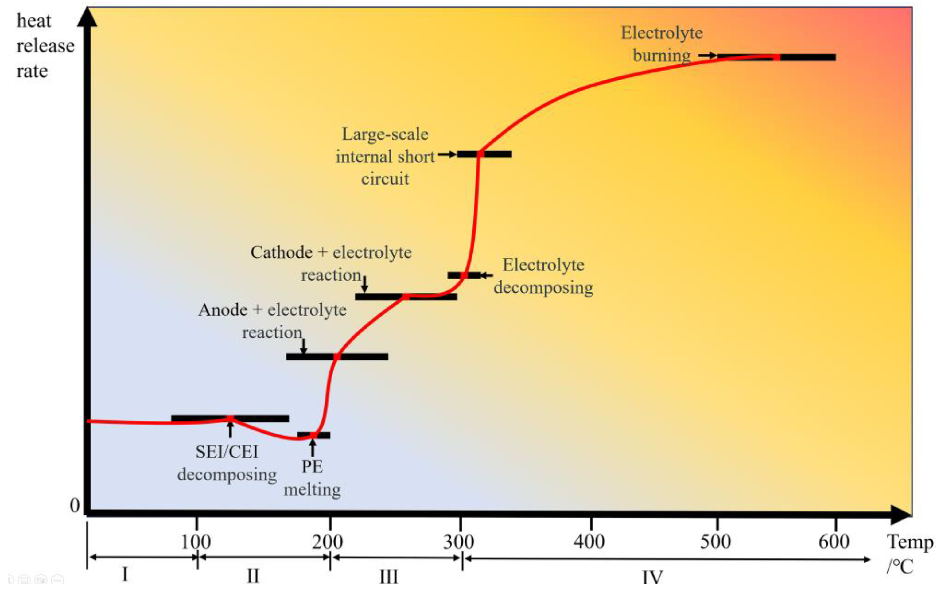
Figure 1. Thermal runaway stage.
Energies 18 04240 g001
Figure 2. (a) NRLO cathode structure. “Reproduced with permission [15]. Copyright © 2016 Elsevier”, (b) Z-axis STEM image of the layered cathode material along the [0 0 1] zone. “Reproduced with permission [13]. Copyright © 2014, Springer Nature Limited, (c) LiCoO2 layered structure. “Reproduced with permission [14]. Copyright © 2004, American Chemical Society”.
Energies 18 04240 g002
Figure 6. Schematic diagram of Mn ion migration in LMO surface. “Reprinted with permission from [60]. Copyright © 2017 American Chemical Society”.
Energies 18 04240 g006
Figure 7. Olivine structure of LiFePO4.
Energies 18 04240 g007
Figure 8. Structural comparison of Li2Fe(SO4)2, Li1.5Fe(SO4)2, and Li1.0Fe(SO4)2, the orange and yellow balls represents lithium atoms in Li1 site and Li2 site. Half-colored white-yellow balls represents the half delithiated Li2 site in Li1.5Fe(SO4)2. The box represents the half-life. “Reproduced with permission [85]. Copyright © the Owner Societies 2016”.
Energies 18 04240 g008
Figure 9. Crystal structure of graphite. “Reproduced with permission [88]. Copyright © 2014 Elsevier”.
Energies 18 04240 g009
Figure 10. Schematic diagram of SEI decomposition on LIB anode. “Reproduced with permission [92]. Copyright © 2017 American Chemical Society”.
Energies 18 04240 g010
Figure 11. (a) NC@Si nanospheres. “Reproduced with permission [102]. Copyright © 2023 Elsevier”. (b) SG/Si/C composite “Reproduced with permission [103]. Copyright © 2015 Elsevier”. (c) Dual core–shell Si@SiOx@C composite. “Reproduced with permission [104]. Copyright © 2016, American Chemical Society”. (d) Fabrication of cell-like Si/CNTs anodes. “Reproduced with permission [100]. Copyright © 2020 Elsevier”.
Energies 18 04240 g011
Figure 12. Challenges from fundamental to practical on the surface of lithium metal anode, “Reproduced with permission [5]. Copyright © 2020 Elsevier”.
Energies 18 04240 g012
Figure 13. Pretreatment process of the LiF-rich SEI [117].
Energies 18 04240 g013
Figure 14. Lithium dendrite growth mechanism of (a) non-woven separator and (b) microporous separator. “Reproduced with permission [135]. Copyright © 2020 Elsevier”.
Energies 18 04240 g014
Figure 15. (a) LLZO garnet crystal structure [167], (b) AxM2(TO4)3 structure. “Reproduced with permission [168]. Copyright © 2021, American Chemical Society.” (c) LZP diamond crystal structure. “Reproduced with permission [169]. Copyright © 2022 Elsevier.” (d) α-Li3PS4 “Reproduced with permission [170]. Copyright © The Royal Society of Chemistry 2020.” (e) Diffusion path of Li ions in LGP [171].
Energies 18 04240 g015
Table 2. Effect of element coating and doping on thermal stability.
MaterialSurface CoatingSurface DopingCharging Voltage
(V)
Heat FlowHeat Release Onset (Peak) TemperatureRef.
LiNi0.8Co0.1Mn0.1O2-Mn4.3Consistent+5 °C (+10 °C)[40]
LiNi0.6Co0.2Mn0.2O2SiO2-4.3−35%+15 °C (+13 °C)[41]
LiNi0.6Co0.2Mn0.2O2TiO2-4.5−20%+10 °C (+8 °C)[42]
LiCoO2Al2O3-4.3−50%+20 °C (−10 °C)[43]
AlPO4-4.3−70%+60 °C (+20 °C)
Li1-x[Ni1/3Co1/3Mn1/3]O2AlF3-4.5−15%+20 °C (+15 °C)[44]
LiNi0.5Co0.25Mn0.25O2ZnO-4.6−23%+4 °C (+5 °C)[45]
LiNi0.5Co0.2Mn0.3O2BMI/TCA-4.3−15%Consistent[38]
Table 3. Effects of element doping and surface coating on thermal stability of LMO cathode.
CoatingDopingCharging Voltage (V)Heat
Flow
Heat Release Onset (Peak) TemperatureQuality LossRef.
-Al4.3--No obvious [73]
-Co4.3−100%Not detected at 350 °C-[74]
-Fe4.3−50%+59 °C (+55 °C)-
-Ni4.3−50%−26 °C (+2 °C)-
-WO2.724.3 [75]
YPO4-4.3−67%+25 °C (+11 °C)-[76]
FeF3-4.5−44%+0 °C (+7 °C)-[77]
LaF3-4.3−44%+0 °C (+9 °C)-[78]
LiCoO2-4.3−40%+10 °C (+14 °C)-[79]
N-C----Carbon layer loss 6.3%[64]
LiNi0.5Mn1.5O4-4.3−11%Slightly improved-[80,81]
Table 4. Different improvement methods for anode thermal stability.
MaterialImprovement MethodOperating Voltage (V)Thermal Stability EvaluationRef.
GraphiteSurface coating
PEDOT:PSS
4.1Heat flow reduced by 29%
The amount of heat released when SEI decomposes is reduced by 74%
[94]
Surface coating
PEDOT:PSS/CB
4.1Heat flow reduced by 9%
The amount of heat released when SEI decomposes is reduced by 29%
Surface coating
C
-The weight loss onset temperature increases by about 100 °C[125]
Surface doping
P
0.01 (Relative to Li/Li+)Heat flow reduced by 11%
Exothermic peak is
significantly reduced
[93]
Surface doping
B
0.01 (Relative to Li/Li+)Heat flow reduced by 3%
The exothermic peak is
significantly reduced
SiliconCore shell structure
NC(core)Si(Shell)
-Maximum weight loss
reduced by 21%
[102]
Double shell structure
SG(core)Si(Shell)C(Shell)
-The volume expansion is
significantly suppressed
Maximum weight loss
reduced by 20%
[103]
Sea urchin structure
Si/CNT
-The volume expansion is
significantly suppressed
[100]
1 M LiPF6 EC/DEC = 1:1
Dropping FEC
0.005
(Relative to Li/Li+)
Exothermic onset temperature increases by 47 °C
Peak temperature increased by 34 °C
[106]
1 M LiPF6 EC/DEC = 1:1
Dropping VC
Exothermic onset temperature increases by 61 °C
Peak temperature increased by 56 °C
1 M LiPF6 EC/DMC = 1:1
Dropping TCN
-Exothermic onset temperature increases by 5 °C
Peak temperature increased by 1 °C
Heat release reduced by 37%
Maximum weight loss
reduced by 10%
[105]
1 M LiPF6 EC/DEC = 1:1
Dropping APTES
-Heat release reduced by 52%[107]
Si-CuO
Dropping NiO
-Slightly improved[108]
Si
Dropping O
-Heat release reduced by 27%[126]
Si/G@C
Dropping TiN
-The volume expansion is
significantly suppressed (56%)
Exothermic onset temperature increases by 5 °C
Peak temperature increased by 1–3 °C
Heat release reduced by 29%
[127]
Metal compositeLi/Al-Melting point increased by 75 °C[123]
Li/Mg5.0Melting point increased by 18 °C
Heat release reduced by 17%
[124]
Table 5. Thermal stability of different separators using different methods.
MatrixImprovement MethodMelting Temperature
(°C)
Tensile Strength
(Mpa)
Thermal ShrinkageThermal Stability Evaluation
(Thermal Shrinkage Rate at 150 °C)
Ref.
Microporous separatorPECoating SiO2/PEI--150 °C/0.5 h 80%decreases by 10% in 30 min [130]
PECoating LSO-SiO2--150 °C/0.5 h 0%decreases by 72% in 30 min[132]
PECoating Al2O/PDA--140 °C/0.5 h 0%decreases by 36% in 30 min [147]
PECoating ST--150 °C/0.5 h 19%decreases by 51% in 30 min[148]
PEGrafting VTMS143-150 °C/0.5 h 0%
180 °C/0.5 h 20%
decreases by 90% in 30 min [134]
PPCoating Al2O3/PEK-C230-150 °C/1 h 8%decreases by 32% in 60 min [149]
PPCoating PVdF300-To 150 °C 0%no shrinkage [150]
PPCoating BNNT165-To 150 °C 5% shrinks slightly[151]
PP/PE/PPCoating ZrO2170114.45180 °C/0.5 h 50%decreases by 40% in 30 min [129]
Non-woven membraneFPI300 °C heat treatment24831.7-Thermal stability is significantly better than PE[137]
ANFs/PEOHeat treatment280 41.52200 °C/1 h 0%Almost unchanged[138]
PI5 MPa mechanical pressing for 3 min>30031150 °C/1 h 0%Heat shrinkage rate in 60 min at 150 °C is 35% lower than PP[139]
PAN60 °C 20 MPa mechanical pressing for 3 min>303--Significantly better than PP[140]
PISpinning PAALi-16.1160 °C/0.5 h 0%Better than PE[143]
PISpinning TiO2>30024.8To 300 °C 0%Significantly better than PP[152]
PSASpinning SiO2/SA--150 °C/0.5 h 0%Significantly better than PP[144]
PEOSpinning ANFs>20010200 °C/1 h 0%Lower than PP[138]
PUSpinning PMIA-25.23180 °C/0.5 h 2%Heat shrinkage rate in 30 min at 180 °C is 82% lower than PP[145]
PANSpinning PVdF-HFP>16045.8To 160 °C 0%Significantly better than PP[146]
Composite separatorβ-PP/PE135--Thermal stability is significantly better than PP[153]
PP/PE/PP170100180 °C/0.5 h 90%Thermal stability is significantly better than PP[129]
PP/AlPO4/PMMA/PVdF-HFP>170-To 170 °C 50%Thermal stability is significantly better than PP[154]
PMIA/OPS400 21.79240 °C/2 h 0%Thermal stability is significantly better than PP[155]
PMIA@PAN/PVdF-HFP/TiO2>17029.7220 °C/1 h 0%Heat shrinkage rate in 60 min at 220 °C is 100% lower than PP/PE/PP[156]
PAN/PVdF-HFP/PVP32022.13200 °C/1 h 0%Heat shrinkage rate in 60 min at 220 °C is 100% lower than PP[157]
PVdF-HFP/MMT/PMIA>30025220 °C/1 h 0%Heat shrinkage rate in 60 min at 220 °C is 100% lower than Celgard[158]
PEN@PDA-PEI>20024To 200 °C 0%Thermal stability is significantly better than PP[159]
TiO2/PMIA>25026220 °C/2 h 0%Heat shrinkage rate for 120 min at 220 °C is 100% lower than Celgard[160]
Table 6. Thermal stability of different electrolytes using different methods.
ElectrolyteImprovement MethodDecomposition Temperature
(°C)
Thermal Stability EvaluationRef.
Liquid electrolyte1M LiPF6
DMC/EC 1:1
Additive
TMBX
-Effectively inhibits the decomposition of LiPF6 and the absorption of HF[184]
1M LiPF6
DEC/EC 1:1
Additive
TMP
250Increased the heat release temperature by 25%
Total amount of heat released is significantly reduced
[165]
1M LiPF6
EC/EMC 3:7
Additive
DTYP
252Decomposition temperature increased by 30%[185]
1.15M LiPF6
EC/EMC 3:7
Additive
DPOF
231Decomposition temperature increased by 7.4%[166]
1M LiFSI
PC/EMC 1:6
Additive
F3B
>200No obvious decomposition phenomenon at 200 °C[186]
Solid electrolyteLLZODoping Ta1600Decomposition temperature is increased by 26% compared to LATP[187]
LLZODoping Ga-Y>900Decomposes 0.29% when exposed to water at 900 °C[178]
Li3PS4Doping Si>600Temperature at which β phase transitions to α phase increases by 33%[170]
Polycrystalline Li2SnS3-750Thermal stability is equivalent to Li10SnP2S12[179]
Li3PS4Doping LiI-After 540 min of exposure to the atmosphere, H2S is reduced by 88%[180]
PAN/PVC/LiTFSI315Thermal stability increases with increasing LiTFSI content[181]
PAN/PO3TFSI/LiTFSI300No obvious shrinkage at 450 °C and no burning under open flame.[188]
PAN/PVdF/LiClO4/LLTO500No obvious shrinkage occurs at 500 °C[189]
PI-LLZTO/PVDF380No obvious shrinkage occurred after heat treatment at 150 °C for 30 min.[190]
Disclaimer/Publisher’s Note: The statements, opinions and data contained in all publications are solely those of the individual author(s) and contributor(s) and not of MDPI and/or the editor(s). MDPI and/or the editor(s) disclaim responsibility for any injury to people or property resulting from any ideas, methods, instructions or products referred to in the content.