Article

Early Detection of ITSC Faults in PMSMs Using Transformer Model and Transient Time-Frequency Features

1
Department of Power Electronics and E-Drives, Audi Hungaria Faculty of Automotive Engineering, Széchenyi István University, 9026 Györ, Hungary
2
John von Neumann Faculty of Informatics, Óbuda University, 1034 Budapest, Hungary
*
Authors to whom correspondence should be addressed.
Energies 2025, 18(15), 4048; https://doi.org/10.3390/en18154048
Submission received: 29 June 2025 / Revised: 18 July 2025 / Accepted: 21 July 2025 / Published: 30 July 2025
(This article belongs to the Special Issue Application of Artificial Intelligence in Power and Energy Systems)

Abstract

Inter-turn short-circuit (ITSC) faults in permanent magnet synchronous machines (PMSMs) present a significant reliability challenge in electric vehicle (EV) drivetrains, particularly under non-stationary operating conditions characterized by inverter-driven transients, variable loads, and magnetic saturation. Existing diagnostic approaches, including motor current signature analysis (MCSA) and wavelet-based methods, are primarily designed for steady-state conditions and rely on manual feature selection, limiting their applicability in real-time embedded systems. Furthermore, the lack of publicly available, high-fidelity datasets capturing the transient dynamics and nonlinear flux-linkage behaviors of PMSMs under fault conditions poses an additional barrier to developing data-driven diagnostic solutions. To address these challenges, this study introduces a simulation framework that generates a comprehensive dataset using finite element method (FEM) models, incorporating magnetic saturation effects and inverter-driven transients across diverse EV operating scenarios. Time-frequency features extracted via Discrete Wavelet Transform (DWT) from stator current signals are used to train a Transformer model for automated ITSC fault detection. The Transformer model, leveraging self-attention mechanisms, captures both local transient patterns and long-range dependencies within the time-frequency feature space. This architecture operates without sequential processing, in contrast to recurrent models such as LSTM or RNN models, enabling efficient inference with a relatively low parameter count, which is advantageous for embedded applications. The proposed model achieves 97% validation accuracy on simulated data, demonstrating its potential for real-time PMSM fault detection. Additionally, the provided dataset and methodology contribute to the facilitation of reproducible research in ITSC diagnostics under realistic EV operating conditions.

1. Introduction

Interior permanent-magnet synchronous machines (IPMSMs) are critical components of modern electric vehicle (EV) drivetrains, valued for their high efficiency, compact design, and robust operational reliability. However, inter-turn short-circuit (ITSC) faults represent significant operational risks, as even minimal winding defects can escalate into severe, irreversible damage such as permanent magnet demagnetization and diminished machine reliability [1,2]. Timely detection and accurate diagnosis of these faults are essential to avoid costly downtime, enhance operational safety, and sustain machine performance, especially given the increasing adoption of and reliance on EVs globally. Despite these imperatives, the availability of comprehensive and realistic datasets tailored specifically for ITSC fault analysis remains limited.
Approaches that involve physically induced faults, such as those derived from measurements under controlled short-circuit conditions [3], deliver critical insights but entail destructive tests, extensive experimental setups, and limited generalizability across various machine designs. Alternatively, finite element method (FEM) simulations offer high-quality synthetic datasets but require intricate machine models, significant computational efforts, and careful modeling of transient states to detect subtle fault signatures [4]. For instance, the approach proposed in [5], utilizing stray magnetic field sensing, effectively captures flux variations from faults via FEM simulations and experimental validations. However, it neglects magnetic saturation effects, which are pivotal in fault evolution during high-load conditions. Additionally, intellectual property constraints and highly specific machine configurations further inhibit data sharing, consequently forcing redundant data generation efforts and impeding technological progress.
The growing reliance on machine learning (ML) and artificial intelligence (AI) techniques in motor and EV diagnostics highlights the increasing need for large, high-fidelity datasets [6,7]. These techniques thrive on diverse and accurate data to train and validate advanced diagnostic algorithms. However, recent studies [8] have identified significant gaps in the diagnostic landscape, particularly the lack of datasets and fault features tailored for incipient faults involving minimal shorted turns under transient or saturation conditions. Traditional diagnostic methods and recent ML-based approaches [9] have demonstrated efficacy in steady-state analysis and multi-source fault identification but fail to provide actionable data or features under non-stationary and saturated operating scenarios. Addressing these limitations is critical for advancing robust ITSC diagnostics in PMSMs suitable for real-world EV applications. For example, the ANN-based fault diagnosis framework proposed in [10] leverages features such as Total Instantaneous Power (TIP), Phase Shift (PS), and Negative Sequence Voltage (NSV) for SITSC fault detection. While effective under steady-state conditions, these features lack the robustness needed to capture transient dynamics and magnetic saturation effects, which are essential for real-time fault diagnostics in EV drivetrains. This highlights the urgent need for advanced feature identification methods and models that can address the nonlinear and dynamic behaviors characteristic of EV applications.
The absence of robust tools and datasets capturing transient behaviors and saturation effects in ITSC fault models has resulted in reliance on oversimplified models that fail to accurately represent early-stage fault characteristics. Few state-of-the-art studies address the detailed, operation-specific requirements for EVs. For example, the model presented in [11] analyzes faults with as few as one shorted turn, providing insights into current behavior under varying fault resistance and operational conditions. This model explicitly incorporates magnetic saturation effects through inductance variations derived from FEM simulations in a four-dimensional lookup table, accounting for nonlinearities caused by high fault currents. However, transient dynamics are not explicitly modeled, and while the study employs Field-Oriented Control (FOC) to simulate closed-loop machine responses, it does not propose specific small-scale features suitable for ML applications. Furthermore, the dataset is limited to steady-state conditions and specific machine configurations, lacking the transient fault features essential for developing ML-based diagnostic tools. Although the model demonstrates high consistency between experimental and simulated results, it does not provide quantified detection metrics (e.g., accuracy or error rates) for fault classification.
Similarly, research by Zafarani et al. [12] investigates low-intensity faults, such as the case of 8/71 (approximately 11%) of one phase’s coils being shorted. However, it does not explore finer granularity for fewer shorted turns. Magnetic saturation effects are partially considered, revealing how flux density distribution changes with fault intensity, but the study does not address transient behaviors specific to EVs, such as rapid torque and speed changes. Both open-loop and closed-loop conditions are analyzed, including the impact of controllers on fault dynamics, but the dataset is not optimized for ML feature extraction, particularly for incipient faults. Furthermore, the dataset lacks transient dynamics, low-speed saturation effects, and generalized fault conditions across diverse machine types, limiting its applicability for ML-based methods aimed at detecting incipient faults during dynamic EV operations. These limitations emphasize the pressing need for datasets and simulation frameworks that enable the identification of fault features under real operating conditions, facilitating the development of high-precision fault-diagnostic methods.
As EV systems grow more complex and interconnected, integrating fault detection models into digital twins and virtual prototyping platforms, as demonstrated in the VISION-xEV framework [13], can enable agile predictive maintenance strategies. Such frameworks facilitate the simulation of real-world operating conditions, optimizing system-level performance while reducing development cycles. However, existing methods, including VISION-xEV, still lack explicit consideration of magnetic saturation effects and transient fault feature extraction, further highlighting the need for advanced diagnostic solutions tailored to these scenarios.
Despite their proven effectiveness across various domains, Transformer models have remained largely unexplored in electrical machine fault detection, particularly for ITSC faults in PMSMs, where non-stationary operating conditions and transient fault events present unique challenges. Existing fault detection methodologies struggle to capture these dynamic behaviors effectively, underscoring the need for advanced modeling approaches like Transformers that can autonomously learn and adapt to such complex temporal patterns. Existing research predominantly relies on signal processing-based methodologies, including motor current signature analysis (MCSA), wavelet transformations, or hybrid approaches combining distance metrics and time-frequency decompositions [14,15,16]. While these methods offer valuable insights in certain conditions, they often necessitate manual feature extraction, empirical thresholding, or visual scalogram analysis, limiting their scalability and adaptability to complex, non-stationary environments typical of EV applications. Recent work such as [17] illustrates the use of Gamma indices and feature engineering in field-oriented control (FOC)-driven induction motors for fault detection, yet these approaches remain confined to specific drive conditions and lack generalizability to inverter-fed PMSMs under transient scenarios.
In contrast, recent advancements in deep learning, particularly Transformer architectures, have revolutionized sequential modeling in domains such as natural language processing, computer vision, and time-series forecasting [18,19]. Transformers leverage attention mechanisms to capture local and global dependencies, overcoming the limitations of recurrent networks. However, most Transformer adaptations for time-series applications, including those presented by Kämäräinen [19], focus on periodic signal forecasting, addressing relatively simple datasets and overlooking the non-stationary, transient characteristics inherent in PMSM fault signals. A Transformer-based diagnostic scheme is introduced in which wavelet-transformed stator-current components, i d and i q , are supplied to the network for automated detection of incipient inter-turn short-circuit (ITSC) faults in inverter-driven permanent-magnet synchronous machines (PMSMs). For this purpose, a dedicated high-fidelity finite element framework is designed to generate flux-linkage look-up tables (LUTs) that encompass both linear and saturated regimes; the inversion of these tables enables efficient real-time execution on FPGA and System-on-Chip (SoC) targets.The inverter-controlled transient behavior of the drive is subsequently co-simulated in Simulink over an extended operating envelope. From these simulations, short time-localized windows of the stator currents are extracted and subjected to wavelet analysis, yielding time-frequency representations that serve as input tokens to a Transformer encoder. Owing to its self-attention mechanism, the network autonomously learns discriminative temporal features, obviating the manual thresholding and feature engineering required by conventional motor-current signature analysis and wavelet-only techniques. Therefore, the pipeline is able to identify early-stage ITSCs under strongly non-stationary conditions, including rapid torque transients and magnetic saturation. To the authors’ knowledge, this constitutes the first application of a Transformer architecture to PMSM early ITSC diagnosis suitable for real-time application under transient conditions, also demonstrating that the combination of physics-based simulation data and sequential attention modeling provides robust, real-time fault detection suitable for next-generation electric-vehicle powertrains.

2. Methods

2.1. Modeling PMSM with ITSC

A schematic diagram of a PMSM with one shorted turn in phase W is shown in Figure 1. In this configuration, the faulted phase can be divided into a faulted part, characterized by an additional resistance ( R f ) that represents the damaged insulation and a healthy part. The fault current ( i f ) circulates within the shorted turn loop, forming an independent current path that interacts with the main stator windings, thereby influencing the flux linkages along the d and q axes. While the abc-reference frame directly mirrors the machine’s physical structure, reformulating the equations within the dq-reference frame decouples the system dynamics, thereby facilitating streamlined real-time simulation, controller design, and diagnostic strategy development.
After transformation, the stator equations can be described as [1] given by Equation (1) below:
u d u q = R s 0 0 R s i d i q d + d d t ψ d ψ q + ω e ψ q ψ d μ 2 3 R s cos θ e + 2 π 3 sin θ e + 2 π 3 i f ,
where μ = N s h o r t N t o t a l is the ratio of shorted turns. The faulted turn voltage in the dq frame is given by
u f = R f i f = = μ R s ( i d s i n ( θ e + 2 π 3 ) + i q c o s ( θ e + 2 π 3 ) i f ) + d ψ f d t .
Rearranging the equations into ordinary differential equation (ODE) form yields Equations (3) and (4) as follows:
d d t ψ d ψ q = u d u q R s 0 0 R s i d i q ω e ψ q ψ d + + μ 2 3 R s cos ( θ e + 2 π 3 ) sin ( θ e + 2 π 3 ) i f
d ψ f d t = R f i f μ R s ( i d s i n ( θ e + 2 π 3 ) + i q c o s ( θ e + 2 π 3 ) i f )
An overview of the described model is shown in Figure 2. The calculation of the stator currents and the complexity of the model are influenced by the level of detail in the flux-linkage relationship. In this study, the effect of saturation on incipient inter-turn short-circuit faults is analyzed; therefore, the machine fluxes are described by nonlinear functions [1], such as the following:
ψ d = f ( i d , i q , i f , θ e ) ψ q = f ( i d , i q , i f , θ e ) ψ f = f ( i d , i q , i f , θ e ) M e = f ( i d , i q , i f , θ e ) .
Consequently, if the flux maps are invertible, the stator currents are the nonlinear inverse functions of the fluxes, as given by Equation (6).
i d = f ( ψ d , ψ q , ψ f , θ e ) i q = f ( ψ d , ψ q , ψ f , θ e ) i f = f ( ψ d , ψ q , ψ f , θ e ) .
Due to the complexity of implementing inverse flux functions directly within Field-Programmable Gate Array (FPGA) or System-on-Chip (SoC)-based real-time simulators, the four-dimensional maps are stored in look-up tables (LUTs). Because only fluxes can be measured during testbench and finite element analysis (FEA) simulations, inverse maps must be generated through numerical methods. Furthermore, high-fidelity flux maps for faulted machines are often unavailable, and the process of collecting the necessary data points is time-consuming.
The approach described in this study provides an easily accessible dataset and workflow designed to facilitate the rapid development of ITSC fault diagnosis and control techniques and the efficient implementation of high-fidelity, real-time models [20]. This resource is particularly valuable in contexts that require integrated real-time testing and validation environments. Moreover, the proposed framework is readily adaptable to a wide range of machine types, ensuring versatility and broader applicability.

2.2. Discrete Wavelet Transform

Inter-turn short-circuit (ITSC) faults in permanent-magnet synchronous machines (PMSMs) induce non-stationary transient disturbances in the stator current signals. These transient anomalies are localized in time and cannot be effectively captured by conventional spectral methods such as the Fourier transform, which assumes stationarity and provides only global frequency content.
To overcome this limitation, the Discrete Wavelet Transform (DWT) is employed for time-frequency analysis, enabling the decomposition of current signals across multiple frequency bands while retaining temporal localization. The application of DWT in this study is made feasible by the availability of a high-fidelity, simulation-based dataset that accurately replicates the dynamic behavior of PMSM faults under realistic inverter-driven conditions. This dataset provides sufficient resolution and variability to support advanced feature extraction techniques beyond traditional visual analysis of scalograms, allowing the integration of automatic fault detection within embedded systems using AI models.
Mathematically, the DWT represents a signal ( f ( x ) ) as a weighted sum of scaled and shifted versions of a mother wavelet ( Φ ( x ) ). The wavelet coefficients ( f j i ˜ ) at scale j and translation i are computed as follows:
f j i ˜ = f ( x ) Φ j i * ( x ) d x ,
where the discrete wavelet basis function ( Φ j i ( x ) ) is defined by
Φ j i ( x ) = 2 j 2 Φ 2 j x i ,
with j indicating the decomposition level (scale) and i representing the translation (time shift). The scaling factor ( 2 j / 2 ) ensures energy normalization across different scales.
As described in [21], the DWT can also be interpreted as a cascade of high-pass and low-pass filter banks followed by downsampling, where the high-pass filter extracts detail coefficients (high-frequency components) and the low-pass filter retains approximation coefficients (low-frequency components). This process is iteratively applied to the approximation signal at each level of decomposition, producing a multi-resolution representation of the original signal across distinct frequency bands. The decomposition process is illustrated in Figure 3.
The DWT decomposition of a discrete signal ( f [ n ] ) over J levels can be formulated as
f [ n ] = A J [ n ] + j = 1 J D j [ n ] ,
where A J [ n ] represents the approximation at level J and D j [ n ] denotes the detail coefficients at each level (j).
Current features derived from the DWT of the space-vector modulus, which is calculated as
i ¯ = i d 2 + i q 2 ,
are utilized as input to the Transformer model, enabling automated, embedded fault detection systems that would otherwise rely on manual interpretation of scalograms or handcrafted features.

2.3. Transformer Models

Transformer models process sequential data using the self-attention mechanism, which enables the model to dynamically focus on different parts of an input sequence. Given a set of input vectors ( { x n } , where each x n R D ), these vectors are organized into a matrix ( X R N × D , where N is the sequence length and D is the feature dimension) [18].
The core computation is the self-attention mechanism, where each output vector ( y n ) is a weighted sum of all input vectors:
y n = m = 1 N a n m x m ,
where the attention weights ( a n m ) quantify the contribution of each input vector ( x m ) to the output ( y n ). These weights are computed using the scaled dot-product attention:
a n m = exp q n k m / D k m = 1 N exp q n k m / D k ,
with query, key, and value vectors defined as q n = x n W ( q ) , k m = x m W ( k ) , and v m = x m W ( v ) , where W ( q ) , W ( k ) , and W ( v ) R D × D k are learned projection matrices.
In matrix form, the attention output is expressed as follows:
Y = Softmax Q K D k V ,
where Q, K, and V are the matrices of queries, keys, and values, respectively. Further details on multi-head attention, residual connections, and normalization can be found in [18]. This structure allows the Transformer to capture both local transient patterns and long-range dependencies, making it suitable for complex, non-stationary signal analysis such as ITSC fault detection, in contrast to recurrent architectures such as LSTM or RNN models, which often struggle to capture long-term dependencies or require sequential computation, limiting their efficiency for real-time applications.

3. High-Fidelity Dataset Generation for ITSC Fault Detection

3.1. Static Data Generation

3.1.1. Mapping the Flux-Linkage Relationships

In this section, the framework and procedures for generating flux maps, current maps, and torque map are presented. The dataset is constructed from flux maps, current maps, and torque data samples obtained through static finite element method (FEM) simulations of an IPMSM. Static FEM simulations are used to map the machine’s flux-linkage relationships under various current excitations and rotor positions, providing the necessary nonlinear characteristics for subsequent dynamic simulations without the computational burden of transient FEM analyses.

3.1.2. Simulation Workflow

The simulation workflow for synthetic data generation can be seen in Figure 4. The FEM model of the machine is developed using open-source FEMM software. To reduce computational time, static FEMM simulations are executed in parallel across multiple CPU cores, controlled by the Python 3.11 multiprocessing library. Machine identification employs equidistant grid points defined by Equation (14) based on the nominal current range.
I d = { 250 A , 200 A , , 250 A } , I q = { 250 A , 200 A , , 250 A } , I f = { 1250 A , 1000 A , , 1250 A } , Θ e = { 0 , 1 . 5 0 , 3 0 , , 90 0 }

3.1.3. FEM Model

A thoroughly validated IPMSM FEM model of the 2004 hybrid electric Toyota Prius, developed in [22] and widely characterized in the literature [23,24], serves as the baseline for this study. The main specifications of the machine are summarized in Table 1 [
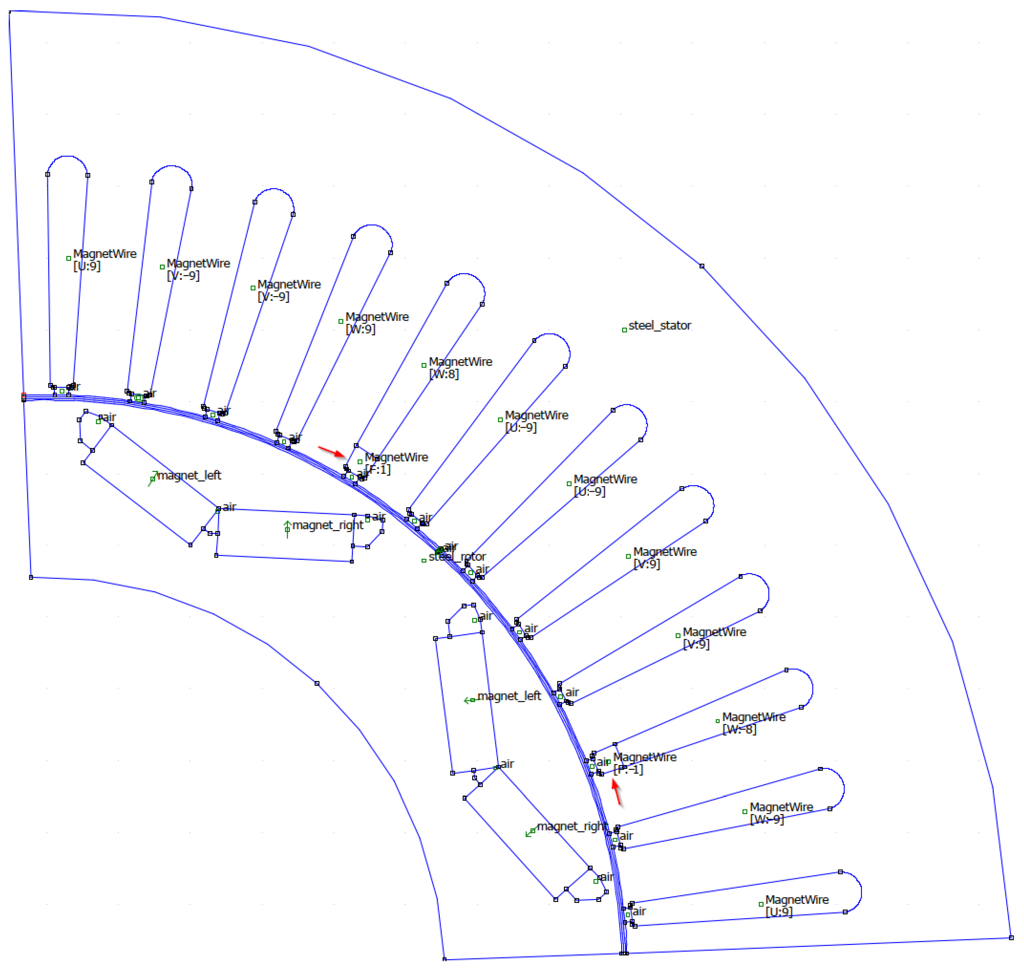
23]. Compared to the Toyota Prius 2004 IPMSM baseline FEM model, the developed model introduces explicit simulation of fault-induced coil segmentation and asymmetric flux-linkage conditions, which is essential for representing ITSC fault dynamics accurately. Furthermore, the flux-linkage lookup tables (LUTs) generated from FEM simulations facilitate direct, real-time implementation in FPGA-based automotive simulation frameworks commonly used in industry for rapid, high-fidelity EV drivetrain prototyping, eliminating the need for repeated FEM computations during testing. Since an ITSC fault causes asymmetric behavior, it is necessary to simulate the entire machine geometry. In order to simulate the fault, the FEM model is modified by partitioning the affected phase coils into two segments. One segment represents the shorted turn, while the other reflects the remaining healthy turns, with a reduced effective number of turns. This arrangement for one pole pair is depicted in Figure 5. The maps are created for one shorted turn; therefore, it is possible to scale fluxes to a higher number of shorted turns [25] (e.g., a fault flux in Equation (
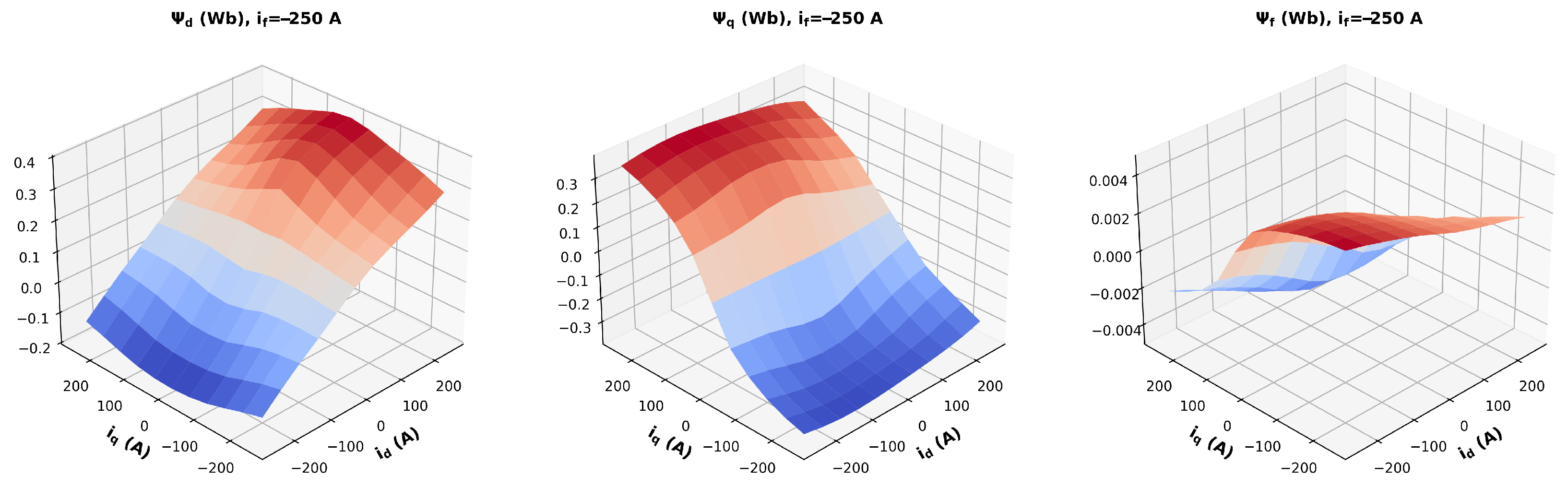
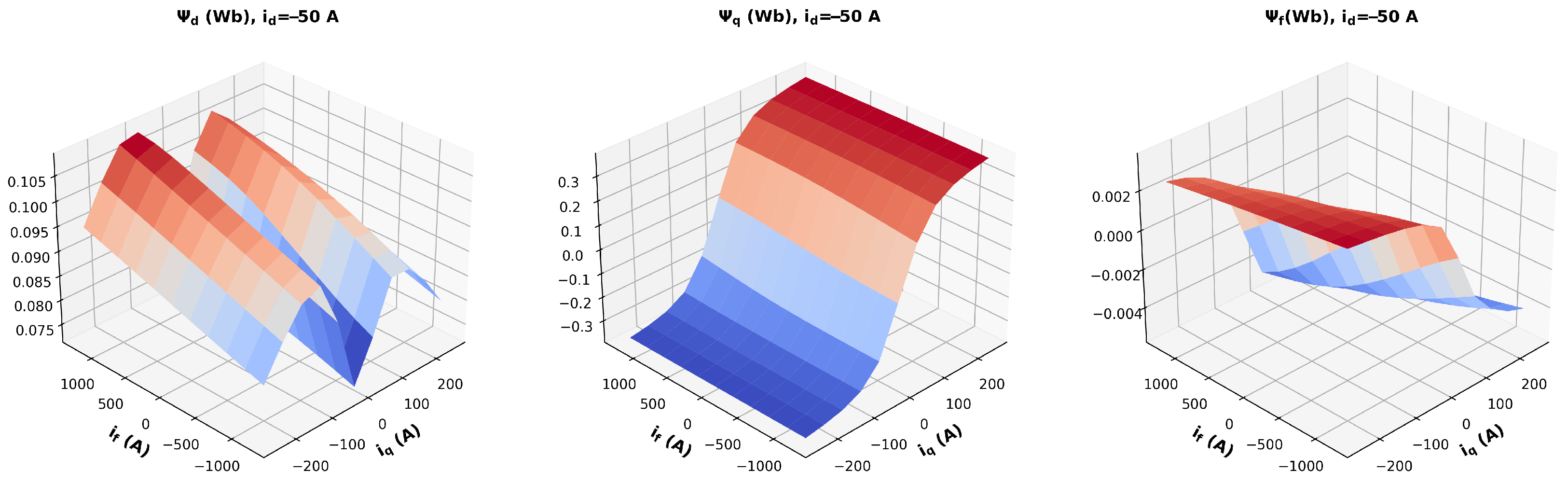
15)). The identified flux maps are depicted in Figure 6 and Figure 7.
ψ f = ψ f N s h o r t e d , i f = i f ( ψ d , ψ q , ψ f , θ e ) N s h o r t e d .

3.1.4. Flux-Map Inversion

For the current calculations in Equation (14), the inverse mapping of the generated flux maps is performed, interchanging the i d , i q , and i f domains with co-domains ψ d , ψ q , and ψ f [26]. The equidistant grid points for the inverse map are determined from the original flux map by using Equation (16).
Ψ x = { ψ x , m i n + j ψ x , s t e p j N , 0 j m } , ψ x , s t e p = ψ x , m a x ψ x , m i n m 1 , ψ x , m i n = m i n ( ψ x ) , ψ x , m a x = m a x ( ψ x ) , x { d , q , f } ,
Here, m corresponds to the number of grid points in the original map. The inverse solution is obtained by minimizing the root-mean-square flux error residual, as described by [4]
Δ ψ t o t = x d , q , f ψ x ( i d , i q , i f , θ e , k ) Ψ x ψ x , m i d 2 , ψ x , m i d = | m a x ( ψ x ) | + | m i n ( ψ x ) | 2 .
The algorithm employs MATLAB’s fminconfunction to iteratively determine the currents that align with the pre-computed flux domain. Normalization using the calculated mid-value ( ψ x , m i d ) is essential for numerical stability, as the fault flux is significantly smaller than the other fluxes [4]. Within the algorithm, the flux function is approximated by using linear interpolation. This inversion process enables the incorporation of complex flux nonlinearity into real-time-capable models, supporting implementations on FPGA or SoC platforms where computational resources are limited.

3.1.5. Technical Validation of Data

The generated flux data is validated by comparing the results and model behavior with findings reported in existing literature [4]. For this purpose, a dynamic Simulink model directly incorporates the FEM-generated flux data [27], and the resulting simulation outputs are compared with those obtained from the inverse flux-map model using the calculated current maps. The model behavior is also compared with experimental measurements from a real-world test bench [28]. The dataset contains measurements of a special-purpose PMSM that realistically emulates the ITSC fault. The main quantities are recorded for different phase faults, numbers of shorted turns, and load torques.
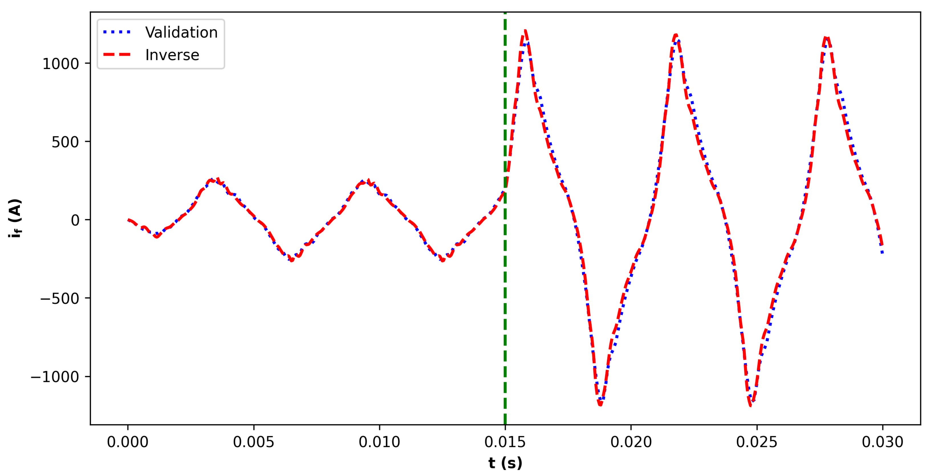
A comparison of the fault current between the flux map-based model and the inverse map model is shown in Figure 8. The detailed W-phase comparison is shown in Figure 9, while the three-phase stator currents of the inverse model are illustrated in Figure 10. In these simulations, the machine operates in generator mode at a speed of 2500 RPM with a 2.2 Ω resistive load. The fault resistance is varied stepwise, decreasing from 10 m Ω to 1 m Ω to analyze the model behavior under different fault current magnitudes.
In Figure 11, the waveform of the experimental data can be seen with four shorted turns in phase V. The machine is operating in motor mode with a 35 Nm load torque.
As demonstrated, the inverse map model closely approximates the flux map-based model, and the flux map-based model, itself, aligns well with findings in the literature. The asymmetric behavior shown by the experimental data can be also observed in the high-fidelity simulation of the faulted PMSM model. These results affirm the reliability of the dataset and the methodology for ITSC fault diagnosis and real-time simulation implementations. While the current approach provides high-fidelity results, further improvements may be achieved by employing finer discretization, more advanced optimization techniques, or higher-resolution solvers to yield even more accurate inverse mappings. This potential enhancement is particularly relevant for critical applications requiring the highest possible accuracy and reliability.

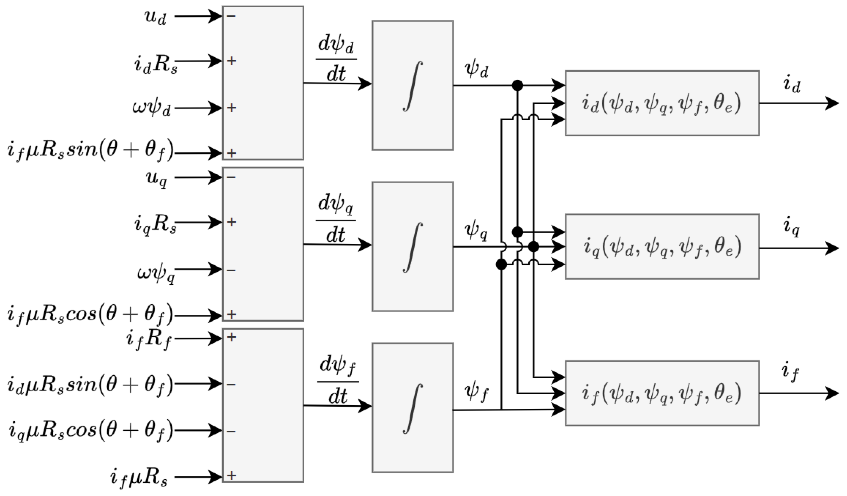
3.2. Transient Data Generation with Simulink

3.2.1. Model

The generated flux maps are integrated into a Simulink-based simulation of an electric vehicle drivetrain controlled using a Field-Oriented Control (FOC) algorithm. The simulated drivetrain includes models of the battery, DC link, inverter, faulty PMSM, and a simplified mechanical system. The inverter model incorporates PWM generation based on duty cycles from the controller and simulates switching behavior. It also generates trigger signals at PWM half-periods to replicate the sampling and computation processes of a real microcontroller-based FOC.

3.2.2. Data Recording

The model simulates intermittent operation modes over a 1-s time window, with a transient event randomly introduced between 0.2 and 0.6 s. The simulation begins at 1000 1 min , and experiments are conducted for different acceleration and deceleration cycles using varying values of n, R f , and M L as defined in Equation (18). The simulations are also repeated for the faults introduced in phases U and V by shifting the electrical angle of the current maps by 2 π 3 and 4 π 3 , respectively.
R f = { 0.001 Ω , 0.002 Ω , , 0.01 Ω } , M L = { 10 Nm , 20 Nm , , 100 Nm } , n a c c e l = { 1150 1 min , 1300 1 min , , 2500 1 min } n d e c e l = { 100 1 min , 200 1 min , , 900 1 min }
The inverter switching frequency is set to 10 kHz. With the triggering mechanism described above, this results in a current sampling rate of 20 kHz for the controller. According to [24], the maximum speed of the machine is approximately 6500 1 min , corresponding to a fundamental current frequency ( f s ) of around 433.33 Hz. This yields a sampling rate that is 46.15 times higher than the fundamental frequency and 23.07 times higher than the Nyquist frequency. Consequently, this sampling rate is sufficient to capture higher-order component harmonics induced by inter-turn short-circuit (ITSC) faults.
Given the 20 kHz sampling rate over a 1 s window and assuming each value is stored as a 32-bit floating-point number, the total data storage required per signal is approximately 78.13 kB. As both i d and i q are stored, the total memory requirement becomes approximately 156.25 kB per simulation. This storage demand is well within the capabilities of modern embedded microcontroller platforms [29], but it is technically feasible to extend memory resources with external devices [30]. The above-mentioned data recording process is depicted in Figure 12.

3.3. Dataset

The simulations described above yielded a comprehensive dataset comprising 6667 transient samples. Each sample contains a 1 s time series of the i d and i q stator-current components sampled at 20 kHz, providing detailed temporal resolution under both healthy and faulty operating conditions. The dataset covers a wide range of operating speeds, mechanical loads, and fault resistances. Faults are introduced independently in all three stator phases (U, V, and W), ensuring exposure to diverse fault conditions.
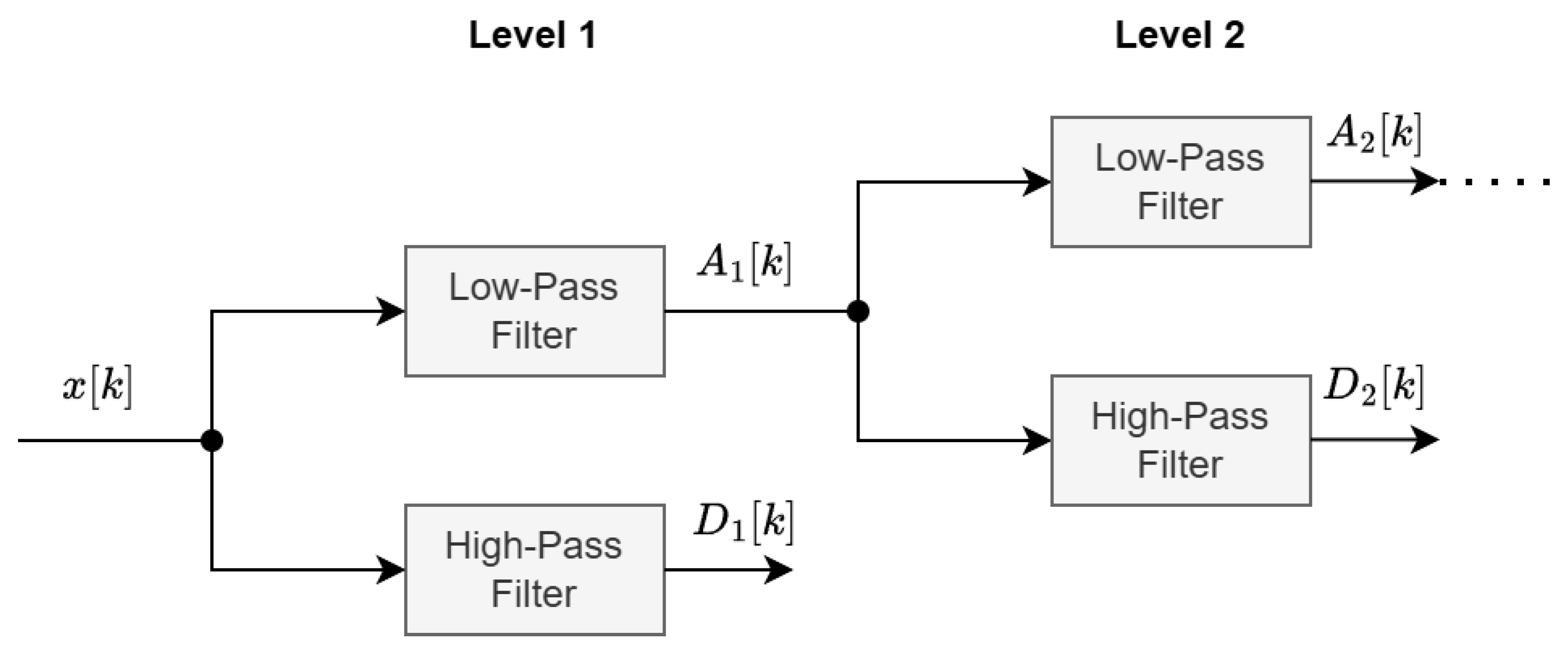
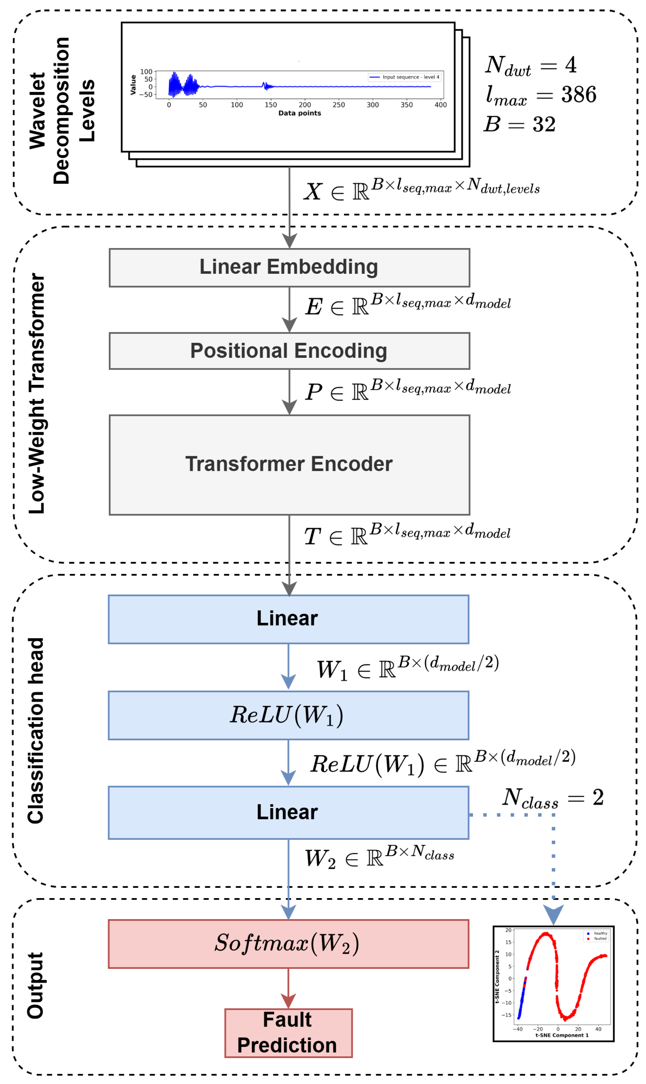
For feature extraction, the Park-vector modulus ( i ¯ ), computed from the i d and i q components, is subjected to discrete wavelet transform (DWT), enabling time-frequency decomposition of the current signals and capturing both transient and steady-state characteristics. The Daubechies-38 mother wavelet is used with eight levels of decomposition.
The Daubechies-38 wavelet is employed due to its high number of vanishing moments, compact support, and capacity to resolve local signal irregularities across multiple scales. This choice is supported by the theoretical relationship between wavelet coefficients and pointwise H older regularity. Specifically, for a function ( f ( t ) ) exhibiting H older regularity of order α at a point t 0 , the decay of wavelet coefficients satisfies
| W f ( a , b ) | C a α + 1 / 2 ,
where a is the scale and W f ( a , b ) denotes the wavelet coefficient at location b [31]. This property allows for the detection of signal singularities such as those associated with incipient inter-turn short circuits, which typically correspond to low- α regions.
This interpretation is supported both theoretically and empirically. In the context of electrical machine fault diagnostics, Zhang et al. [32] demonstrated that higher-order Daubechies wavelets (e.g., db45) combined with level-6 decomposition improved sensitivity to inter-turn short circuits in induction machines. In a broader context, the capacity of wavelet coefficients to capture local regularity has also been exploited in the study of interplanetary magnetic field fluctuations [33]. The general mathematical foundation for this behavior is rigorously described in [31], confirming the suitability of wavelet-based analysis for identifying localized non-stationary phenomena across multifractal signals.
The DWT coefficients of the last four levels from the i ¯ currents are concatenated to form the final feature vectors. This representation is particularly well-suited for detecting inter-turn short-circuit (ITSC) faults, as these faults often manifest as localized, non-stationary anomalies that are not easily captured by conventional Fourier-based spectral methods. The selection of 386 DWT coefficients ensures that the full time-frequency structure of the current signals is captured across multiple decomposition levels, providing the model with detailed representations of both low- and high-frequency components. This comprehensive feature set is particularly important for detecting localized, non-stationary anomalies associated with ITSC faults. Unlike approaches that rely on specific harmonic components or statistical summaries, this method retains the raw, fine-grained coefficients, allowing the Transformer model to autonomously learn and extract relevant patterns from the entire time-frequency space. The raw dataset exhibits an imbalanced distribution, with faulty samples outnumbering healthy ones. To address this issue, oversampling is applied to the healthy class during in the hold-out split training phase, and a stratified k-fold algorithm is applied for cross-validation. Specifically, the indices of healthy samples (labeled as 0.0) are identified within the training subset. These healthy samples are then duplicated five times and combined with the original training data. By concatenating five copies of the healthy subset to the training data, the class distribution is balanced, ensuring that the machine learning model is exposed to an equal representation of healthy and faulty samples during training. The selection of wavelet levels and the five-fold oversampling factor was determined empirically through iterative evaluation of model performance on validation data. This approach aligns with best practices in handling imbalanced datasets for fault detection, where oversampling the minority class mitigates bias during training. The chosen factor ensured stable convergence and balanced sensitivity between healthy and faulty class predictions, without introducing overfitting artifacts commonly associated with excessive duplication. The final dataset, enriched with high-fidelity transient simulation data and time-frequency features, provides a solid foundation for the training of complex deep learning models, particularly Transformer architectures. Its design ensures the dataset’s alignment with real-world EV drivetrain dynamics, supporting the development of robust and generalizable ITSC fault detection systems.

4. Transformer Model for Incipient Fault Detection

In this section, the architecture, training procedure, and implementation details of the Transformer-based fault detection model are presented. This model is designed to detect incipient inter-turn short-circuit (ITSC) faults in permanent-magnet synchronous machines (PMSMs) by analyzing wavelet-transformed stator current signals. The proposed architecture leverages the Transformer architecture’s attention mechanism to autonomously capture both local transient patterns and long-range dependencies in time-frequency feature sequences, overcoming the limitations of traditional recurrent neural networks (RNNs) and long short-term memory networks (LSTMs), which require sequential processing.

4.1. Model Architecture

The input to the model consists of four 386-dimensional feature vectors derived from the discrete wavelet transform (DWT) decomposition of the Park vector modulus ( i ¯ ) over a 1 s sampling window at 20 kHz. From the wavelet decomposition, the most representative levels are kept, which are, in this case, the approximation coefficient and lower frequency bands. These features encapsulate the time-frequency characteristics of the stator current signals, providing a rich representation for detecting localized anomalies associated with ITSC faults.
Since the lengths of the different decomposition levels are not equivalent, the appropriate levels are padded, and a source mask is created in order to neglect padded parts. The input 386-dimensional wavelet coefficient vectors are projected into a sequence of d m o d e l -dimensional embeddings through a linear embedding layer, where each coefficient forms a token within the sequence. This embedding enables the model to process the input sequence as dense vectors. The input scalar wavelet coefficients are first projected into a d m o d e l -dimensional space through a linear embedding layer. Since the Transformer architecture lacks inherent sequential ordering, sinusoidal positional encodings, as defined in [18], are added to the embeddings to incorporate information about the relative positions of the input tokens.
The core of the model consists of a single Transformer encoder layer. This layer employs multi-head self-attention to capture complex temporal dependencies and a feedforward sublayer for additional nonlinear transformations. The encoder configuration is summarized in Table 2. Sequence summarization is achieved through a mean pooling mechanism that aggregates the encoder outputs. Finally, a two-layer feedforward classification head with ReLU activation reduces the pooled vector to a binary output, representing healthy or faulty machine states.
This structure enables the model to process the full sequence of time-frequency features simultaneously, capturing interactions across different time scales without the vanishing gradient issues typical of RNNs or LSTMs. Such capability is crucial for analyzing the non-stationary, transient behaviors inherent in PMSM current signals.
The Transformer model architecture (see Figure 13) comprises a total of 9266 parameters, all of which are trainable, enabling full adaptation during the learning process. The compactness of the model is reflected in its memory footprint, with a total size of approximately 36.2 kB (0.035 MB). This lightweight design facilitates efficient deployment on resource-constrained platforms and supports rapid inference with minimal storage requirements.

4.2. Real-Time Implementation Considerations

The computational cost of the proposed diagnostic pipeline comprising discrete wavelet transform (DWT) feature extraction and Transformer inference was quantified in FLOPs to validate real-time feasibility.

4.2.1. DWT Cost

The DWT applies a pair of high-pass and low-pass filters, followed by downsampling by two at each decomposition level. For an input of window length N and wavelet-order levels L and J, according to [34], the total FLOPs are expressed as follows:
C d w t = 2 L j = 0 J 1 N 2 j ,
since higher levels contribute diminishing work. In our setup, i d and i q are each sampled at 20,000 points over 1 s with J = 8 levels, and Daubechies-38 mother wavelet is used as follows:
DWT FLOPs = 2 · 38 · ( 20000 + 10000 + 5000 + 2500 + + 1250 + 625 + 313 + 156 ) 3.028 × 10 6 FLOPs .
Although only 386 wavelet coefficients (tokens) are retained for the next stage, the application of the full DWT over all samples ensures accurate time-frequency decomposition.

4.2.2. Transformer Cost

The Transformer operates on l m a x = 386 input tokens (the selected wavelet coefficients), with model dimensions of d m o d e l = 32 , h = 16 heads, and a feedforward dimension of 64. The input embedding and the classification head also use linear layers. The computational complexity of the linear layers can be calculated on the basis of Equations (20) and (21):
C e m b e d d i n g = 2 ( N d w t l m a x d m o d e l ) ,
C c l a s s i f i c a t i o n = 2 d m o d e l 2 2 l m a x + 2 d m o d e l 2 N c l a s s l m a x ,
where N d w t is the number of used wavelet sequences, l m a x is the maximum length of wavelet sequences, and N c l a s s e s is the number of output classes. With the hyperparameter setting mentioned above, the input and output embedding costs are 4 · 386 · 32 98816 and 2 · 32 2 2 · 386 + 4 · 38 2 · 386 419968 FLOPs, respectively.
The standard Transformer FLOP count of a forward pass is [35]
C t r a n s f o r m e r = 16 l m a x d m o d e l 2 + 2 l m a x 2 d m o d e l ,
which is evaluated as
16 · 386 · 32 2 6.324 × 10 6 , 2 · 386 2 · 32 9.535 × 10 6 ,
for a total of 15.859 × 10 6 FLOPs per inference.

4.2.3. Total and Timing

Summing the DWT (3.028 × 10 6 FLOPs), the input (98,816 FLOPs), Transformer (15.859 × 10 6 FLOPs), and classification (419,967 FLOPs) stages yields 19.406 × 10 6 FLOPs per cycle. On a 100 MHz MCU capable of 10 8 FLOPs/s, this corresponds to cca. 194 ms per inference, supporting updates at ⩾200 ms intervals under realistic inverter-transient conditions. This inference time is just a rough estimation for a common microcontroller implementation, and significant improvements can be achieved using hardware accelerators [36] and algorithmic techniques [37]. It must be noted that, with the retention of only the four most representative levels of the DWT, the number of input tokens is greatly reduced. In that way, the whole 1 s time window can be analyzed with only 386 tokens instead of the original token number of 20,000.
Thus, the combined full-window DWT and compact Transformer pipeline delivers both high detection fidelity and real-time feasibility for incipient ITSC fault diagnosis in EV drives.

5. Results

The high-fidelity transient dataset used for model training consists of 6667 samples generated from inverter-driven PMSM simulations. To improve generalization and mitigate the effect of class imbalance, three-fold stratified cross-validation is applied, ensuring that the class distribution is preserved in each fold. The use of stratified cross-validation is shown to reduce the variance of evaluation metrics in classification tasks with limited or imbalanced data, as also reported in [38].
In addition, a separate hold-out validation strategy is employed with a 50%/40%/10% split for training, validation, and testing, respectively. This setup enables a fixed evaluation scenario and is specifically used to analyze the attention behavior of the Transformer model. The hold-out ratio was chosen to provide sufficient training capacity while retaining unbiased validation and testing sets. This is a common practice in classification scenarios involving medium-sized datasets.
Finally, in order to evaluate the advantages of the Transformer architecture in case of long-term dependencies of the input sequence, an LSTM-RNN model is trained with same dataset, and the final results of the hold-out validation are compared.

5.1. Cross-Validation Results

The training configuration consists of the Adam optimization algorithm with a fixed learning rate of 0.0001. The model architecture employs a single encoder layer with an embedding dimension of 32 distributed across 16 attention heads. The feedforward network within the encoder uses a dimensionality of 64. The dropout hyperparameter is set to 0 in order to ensure the proper fit of the low-weight transformer model. Input features are linearly projected into the embedding space, and sequence summarization is performed using mean pooling.
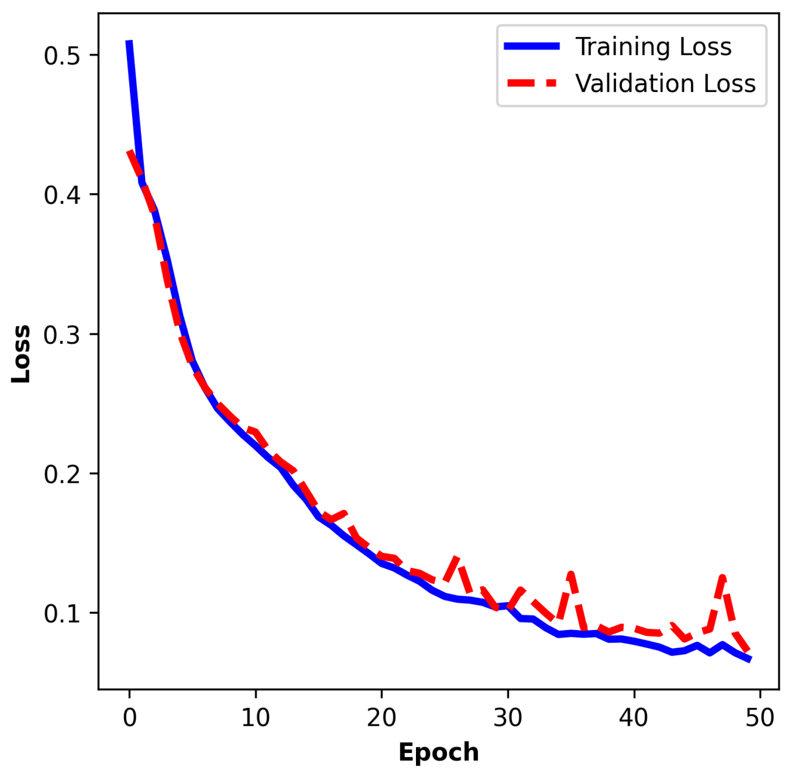
The training process spans 50 epochs, with a batch size of 32 samples and 3 folds. Model evaluation during training reveals steady convergence.
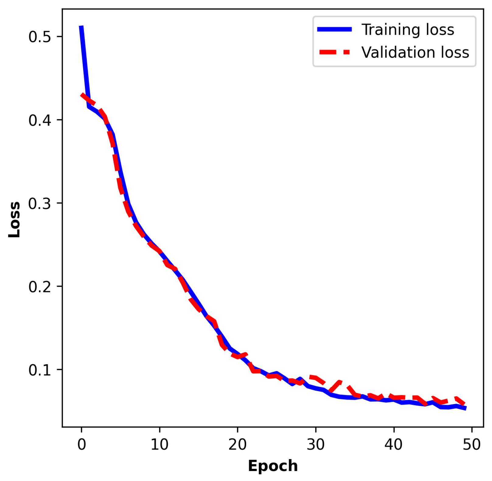
 Figure 14, Figure 15 and Figure 16 illustrate the training and validation loss curves over the course of three folds. In the first fold, the training loss decreases from an initial value of 0.5136 to 0.0638, while the validation loss drops from 0.4314 to 0.0818 by the final epoch. Correspondingly, training accuracy improves from 80.15% to 97.59%, and validation accuracy increases from 85.47% to 96.72%, demonstrating effective generalization without overfitting. The validation loss exhibits a rapid decline during the early stages of training, indicating efficient pattern learning. Similar results can be observed in the other two folds. The close alignment between the two curves suggests good generalization, with minimal divergence between training and validation performance. Table 3 shows the main performance metrics of the experiment. The average scores are above above 94%, which shows notable generalization performance for the fault classification of transient signals.

5.2. Hold-Out Training Evaluation

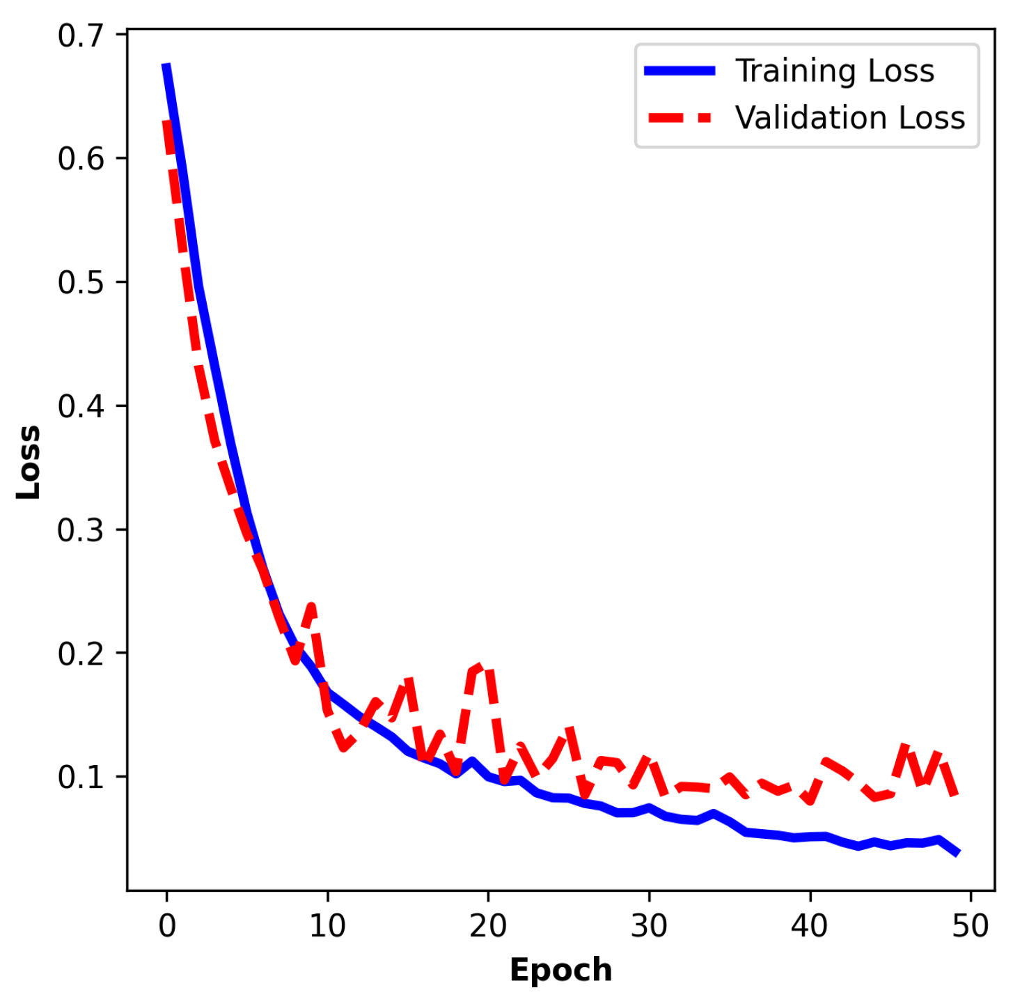
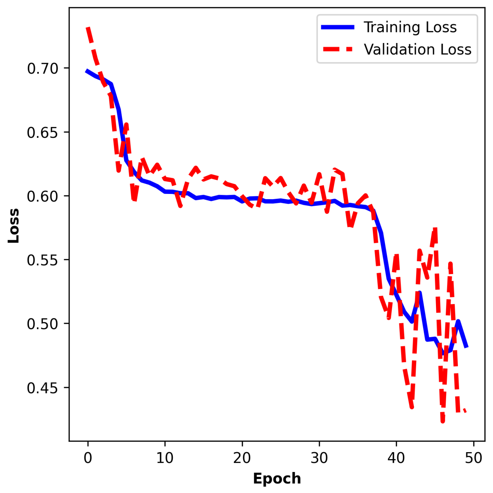
The training curve of the hold-out split training depicted in 
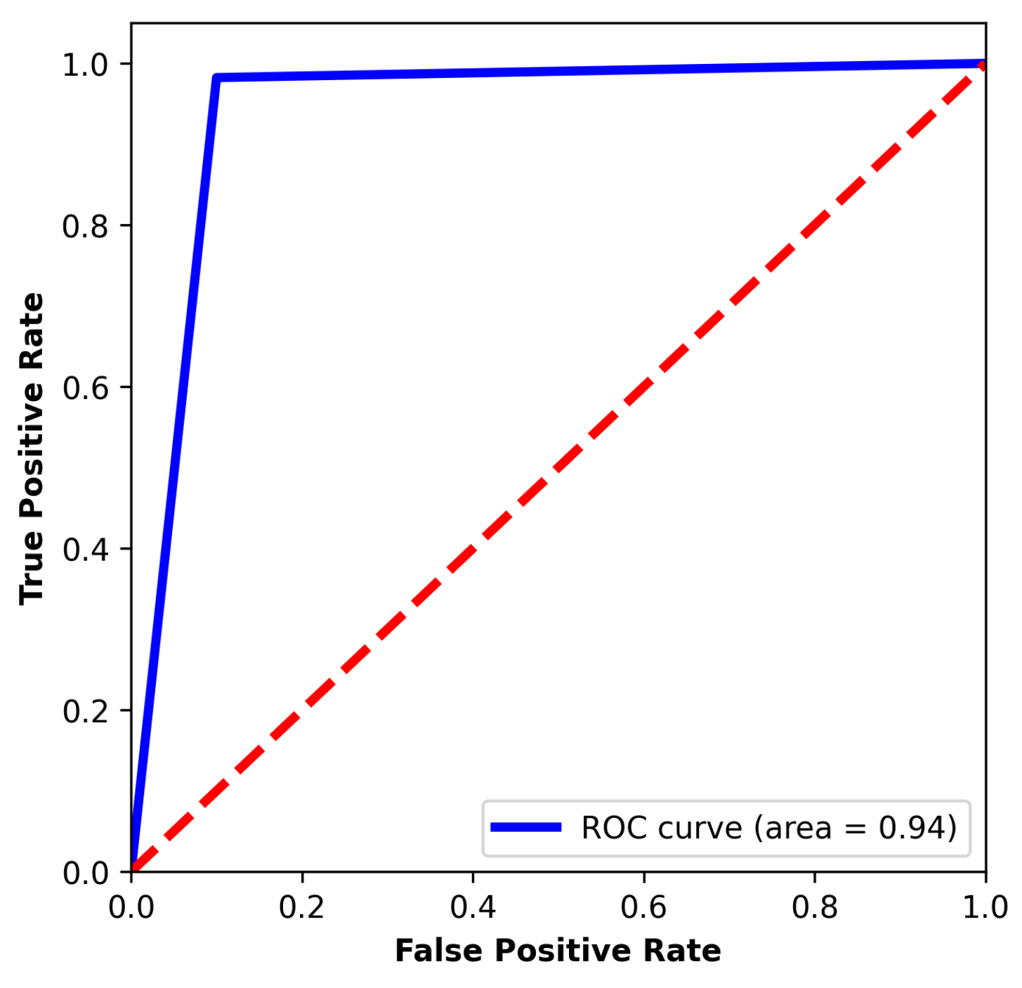
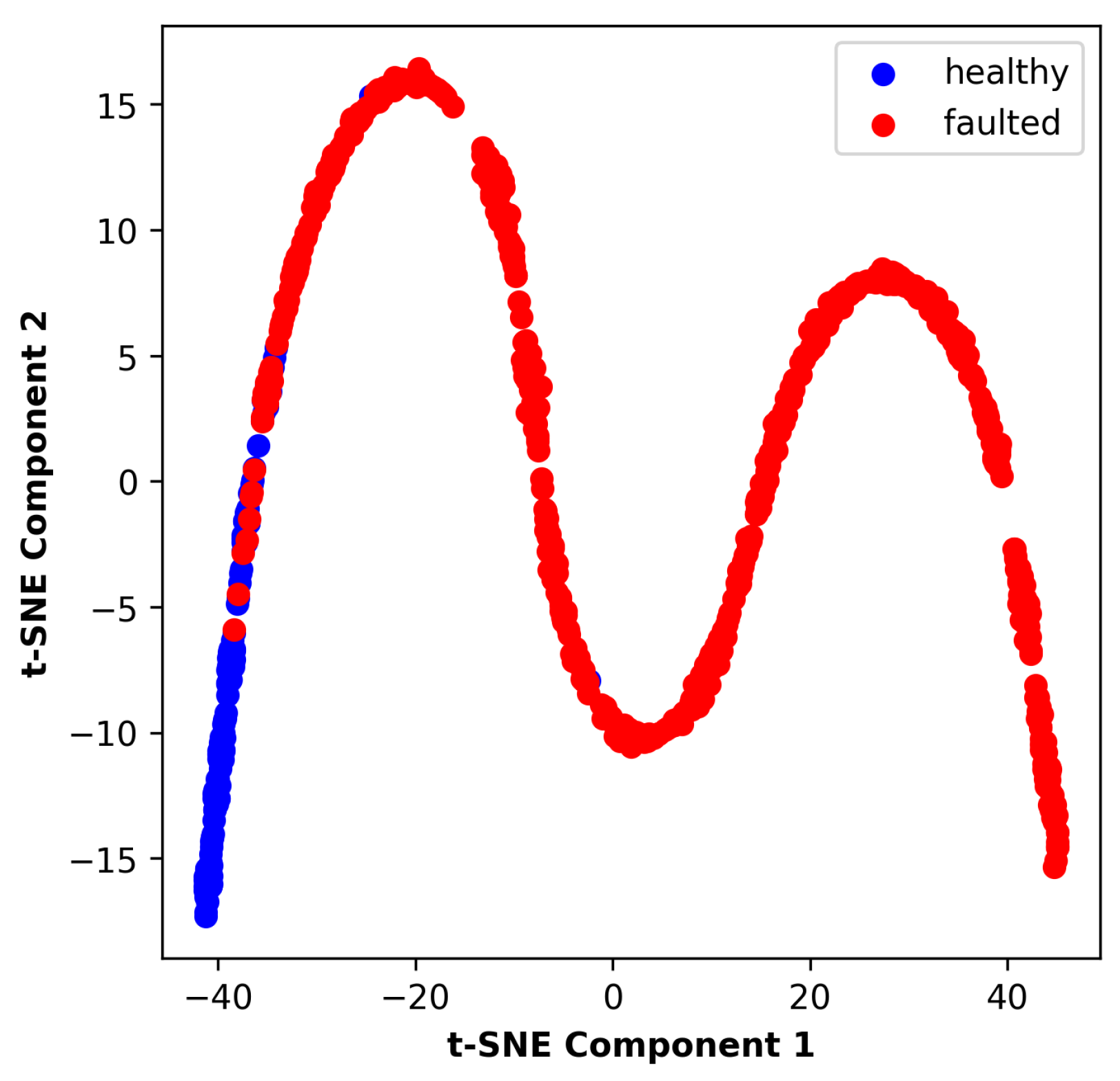
Figure 17 shows performance similar to the K-fold cross-validation training results. The training loss improves from 0.6741 to 0.0767, and the validation loss improves from 0.7008 to 0.0797. The accuracy changes from 59.53% to 96.88% and from 48.80% to 96.92%, respectively. As can be observed in Figure 18 and 
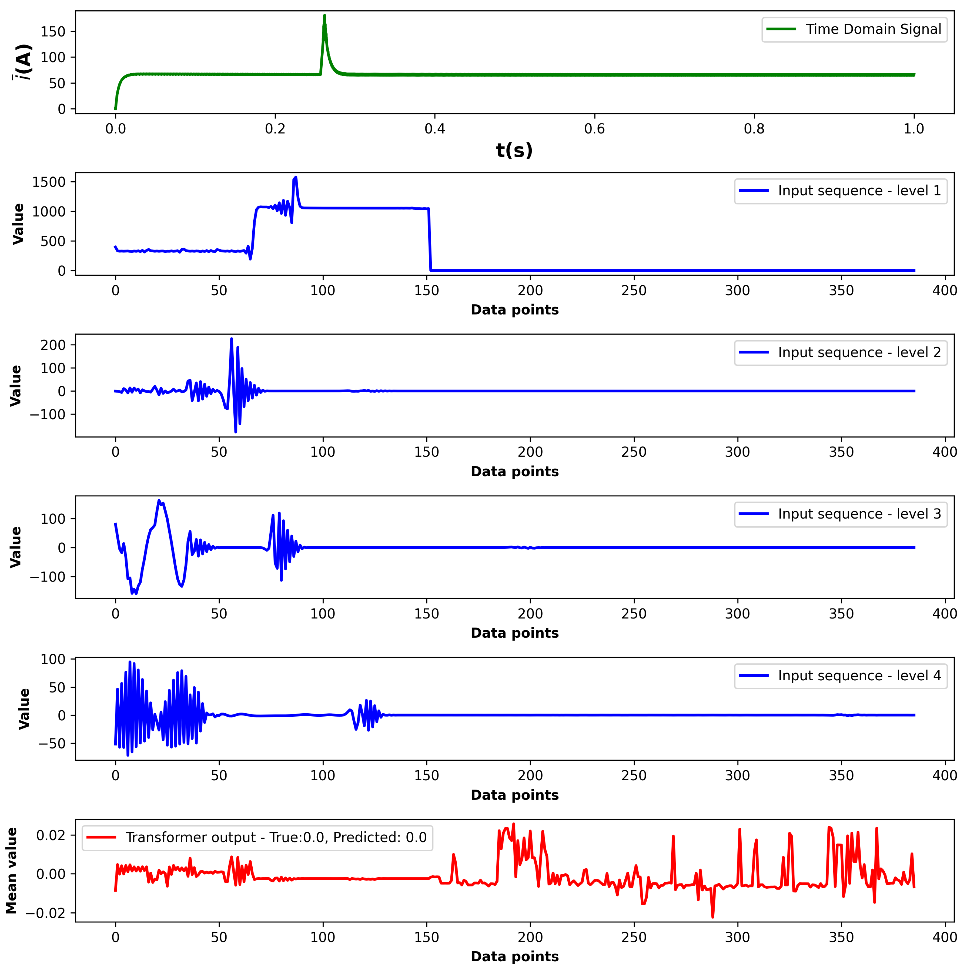
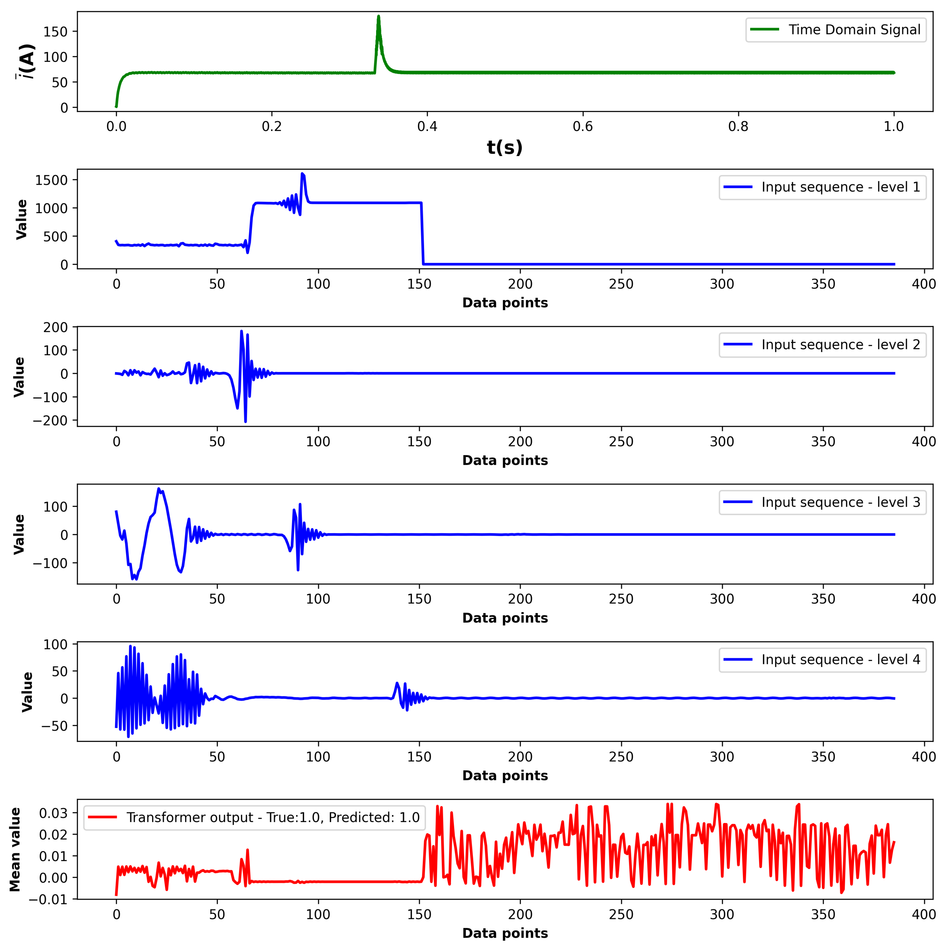
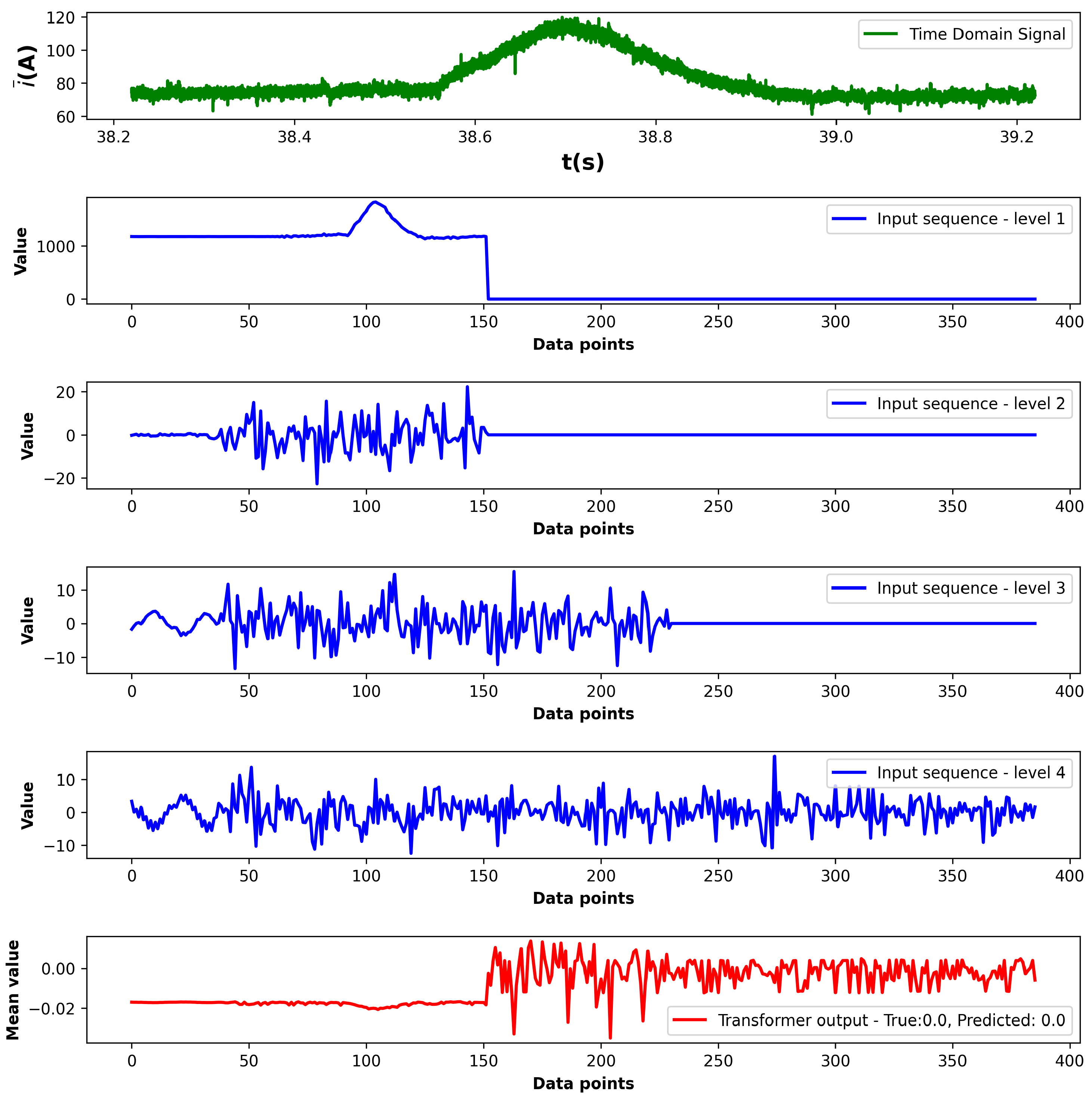
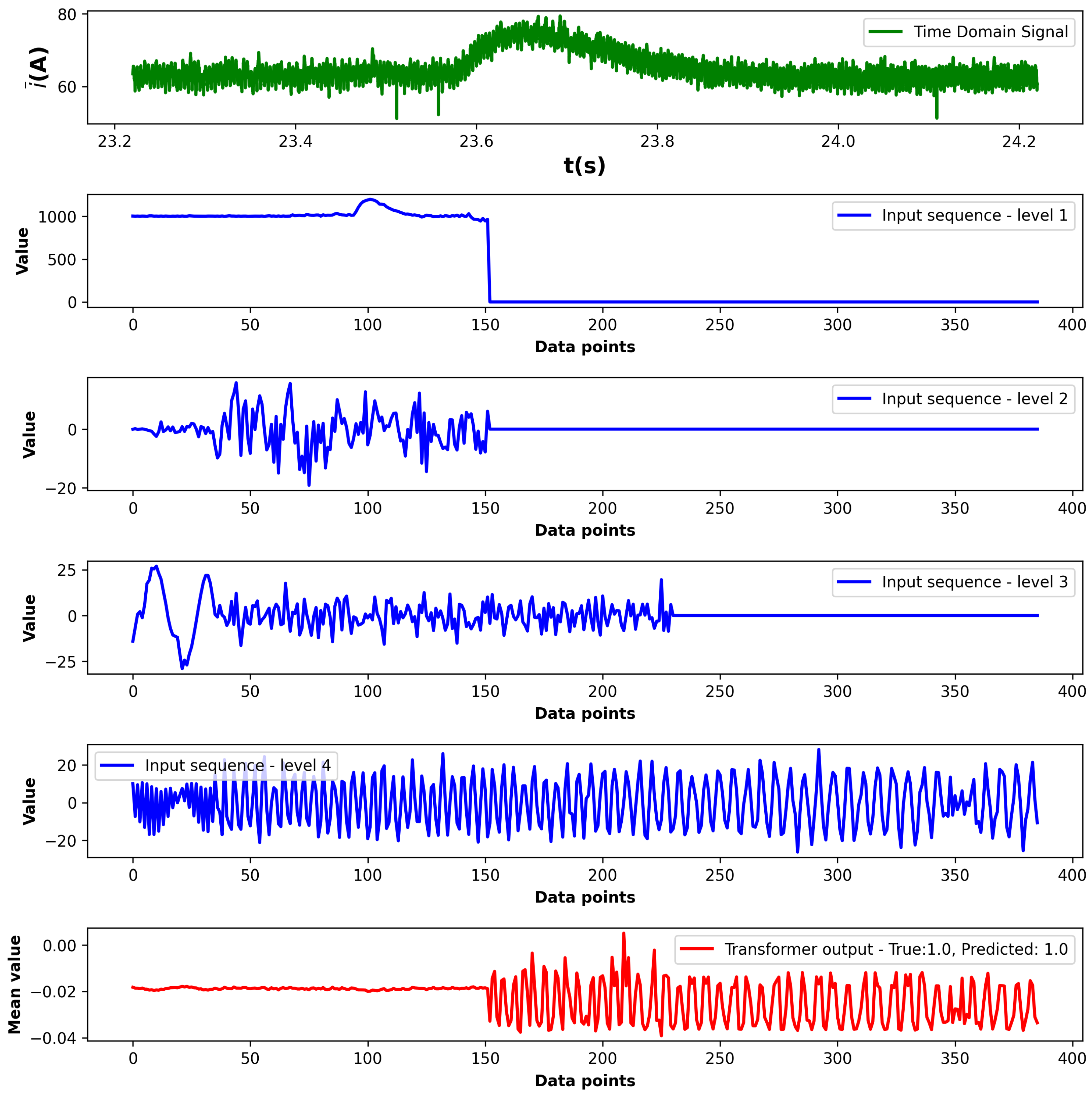
Figure 19, the model demonstrates strong classification performance on the test set and good separability of the output embeddings. Examples of correct healthy and faulted predictions are depicted in Figure 20 and Figure 21. The time-domain waveform shows an acceleration transient to 2050 1 min with a constant load of 90 Nm on the machine. The input sequence lengths are not equivalent; therefore, the lower frequency levels are extended with zero padding. To exclude padded parts from the embedding, a source mask is created for the transformer. The mean values of the transformer encoder outputs shows that the post-transient oscillations in level four have the greatest impact on the prediction. In the case of the healthy sample, it can be observed that the fluctuations in the transformer output are much less frequent compared with the faulted sample.
The combination of wavelet-based feature extraction and Transformer modeling provides a powerful framework for incipient fault detection in PMSMs. The attention mechanism enables the model to prioritize critical time segments associated with fault onset, facilitating real-time implementation in embedded diagnostic systems and supporting predictive maintenance strategies in EV drivetrains.

5.3. Comparison with LSTM-RNN Model

For the comparison, a simple, low-weight LSTM model was built based on the basic architecture proposed in [39]. The hyperparameters of the LSTM-RNN model can be seen in Table 4. The model has four input dimensions for each DWT sequence and 32 hidden states in the recurrent architecture. Since it is a low-weight model, the dropout rate is set to zero.
Although the LSTM-RNN converges after a few epochs, its validation loss remains relatively high and unstable (see in Figure 22), confirming the model’s limitations in capturing the transient characteristics of the input sequences. As can be seen from the results collected in Table 5, the Transformer model outperforms the light-weight LSTM model, since, in contrast with the LSTM, it classifies based on the complete sequence. The inference time of the LSTM model is significantly lower in this setup; however, the performance is not eligible for the low-weight, real-time embedded application.
While LSTM-RNN network excels in traditional time-series prediction tasks, the implemented low-weight architecture lacks the ability to analyze the complex dynamics and long-range temporal dependencies of transient DWT sequences of an EV drive.

5.4. Assessing the Real-World Generalization of a Transformer-Based ITSC Classifier via Transfer Learning

The robustness and generalization capability of the proposed Transformer-based fault detection model are evaluated using publicly available experimental PMSM measurements presented in [
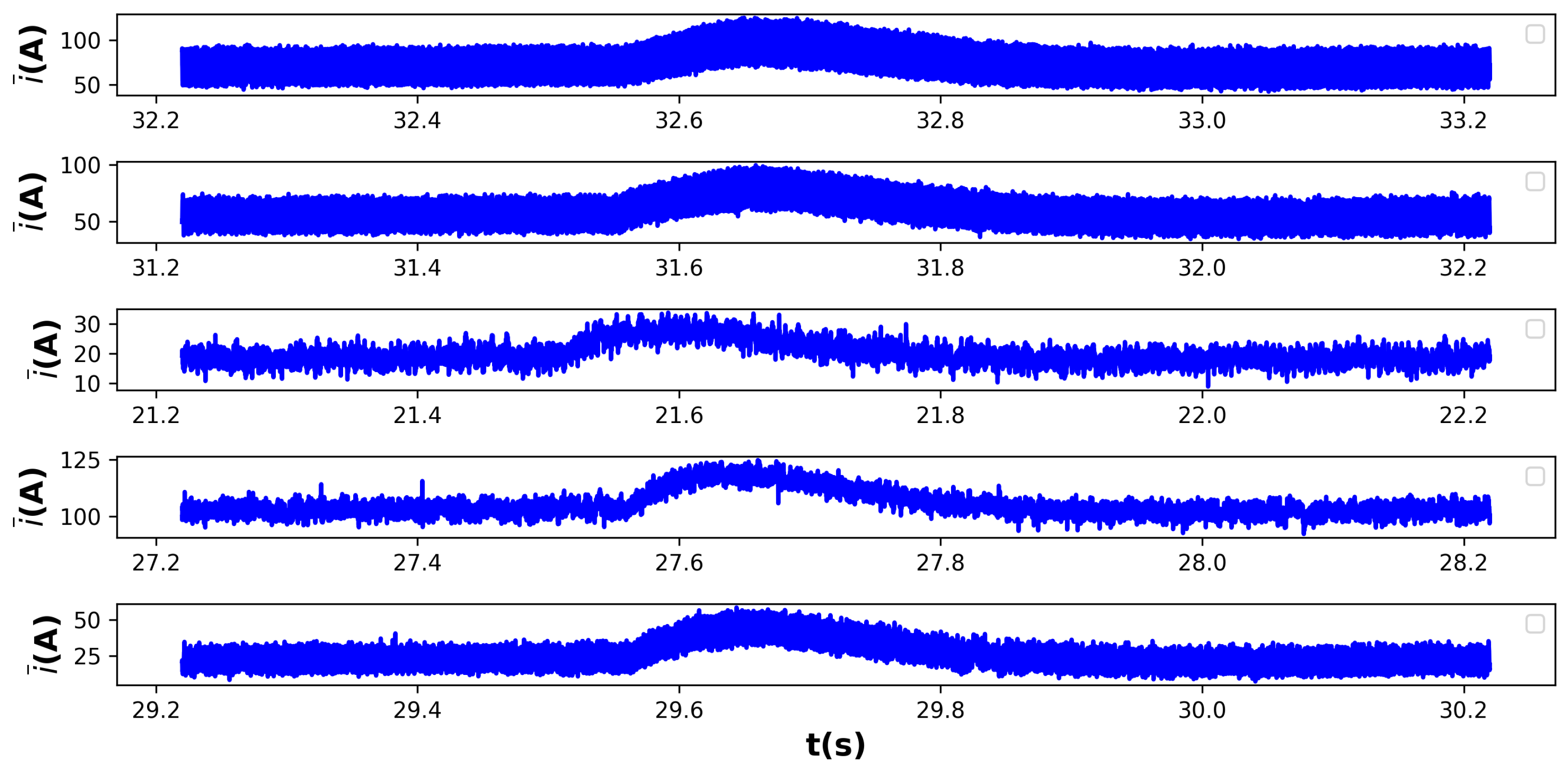
28]. This external dataset includes real-world waveforms collected from a dual three-phase PMSM specifically configured for ITSC fault emulation. Fault intensities cover one to four shorted turns in phases U and V under varied load torque conditions. Examples of acceleration transients from the dataset are depicted in Figure 23.
These measurement scenarios represent realistic EV operating environments and provide a meaningful benchmark for the testing of cross-domain applicability. The model trained on FEM-based synthetic transient signals undergoes transfer learning to adapt to the motor architecture described in [28,40]. This dual three-phase PMSM consists of two electrically separated but magnetically coupled sub-systems and employs a concentric coil structure with 24 stator slots and 10 pole pairs. The motor is explicitly designed to support fail-operational behavior and includes dedicated winding taps for precise ITSC fault injection [40]. In comparison, the motor model used in this paper to generate the synthetic dataset is characterized by a classical three-phase topology and a different winding layout. The dual three-phase configuration [28,40] presents a significantly different internal coil connection scheme and mutual inductance profile, which affect fault current behavior and flux-linkage dynamics. By fine-tuning the pretrained Transformer model on this structurally different motor’s measurement data, its ability to generalize across PMSM configurations is evaluated.
Although the dataset [28,40] reflects real PMSM operation, the noise characteristics and filtering procedures used during acquisition remain undocumented. To compensate for this uncertainty and to simulate a more representative industrial environment, additive zero-mean Gaussian noise is introduced to the measured current signals. The standard deviation of the noise is set to σ = 0.015 A m a x , corresponding to 1.5% of the maximum signal amplitude. This augmentation accounts for typical inverter switching noise and sensor inaccuracies, enabling a realistic robustness evaluation under noisy conditions.
By validating the model under noisy real-world data, the study further examines its transferability to unseen environments. In addition, the FEM-based simulation framework proposed in this paper supports the generation of new synthetic datasets for arbitrary PMSM configurations. This modularity facilitates adaptation of the diagnostic approach to other machines with different pole counts, winding structures, or operational constraints, supporting broader applicability in practical EV systems. The Transformer model, initially trained on the synthetic transient dataset, is fine-tuned using experimental measurement waveforms from transient data samples reported in [28]. During fine-tuning, the early Transformer encoder layers responsible for feature extraction remain fixed, while classification layers undergo further training for 75 epochs at a reduced learning rate ( 1 × 10 3 , Adam optimizer). This approach ensures adaptation to experimental data characteristics without overfitting. Classification results after transfer learning are summarized in Table 6, confirming robust generalization performance across different fault severities. The validation loss shown in Figure 24 indicates a consistent decrease during the epoch with only training of the classification head of the model. This shows that the Transformer encoder and synthetic dataset is capable of generalizing the main features of the faulted transient waveform. The attention weights presented in Figure 25 and Figure 26 show similar behavior as for the synthetic data samples.
This transfer learning setup highlights the model’s capacity to adapt to new domains with distinct electromagnetic characteristics, thereby reinforcing its potential for real-world ITSC fault detection in diverse PMSM-based EV drivetrain architectures. The ability to generalize across motor types, fault severities, and noisy real-world conditions demonstrates not only the flexibility but also the robustness of the proposed diagnostic approach. In particular, the model maintains stable performance despite measurement uncertainties and added Gaussian noise, reflecting its resilience under practical signal quality constraints. Furthermore, the modular synthetic data generation framework enables extension to additional motor designs, supporting future applications in adaptive, data-driven diagnostic systems.

5.5. Benchmarking Against State-of-the-Art ITSC Diagnostic Architectures

Table 7 presents a side-by-side comparison of six representative ITSC diagnosis approaches and our proposed solution. Existing methods either rely on purely analytical or FEM-only studies without machine learning metrics ([41,42]), are validated under steady-state bench conditions only ([43,44,45,46]), or require external sensors and lack EV-specific transient validation ([45,46]). Two references from recent years (2024–2025) have also been considered. A paper by Fan et al. [47] proposed a high-sensitivity hybrid CNN–GRU model using fractional Fourier Mel-spectrogram features to monitor insulation degradation in PMSMs; however, their approach does not target ITSCs and lacks an EV drive cycle and transient testing. Nandakumar and Gunasekaran [48] introduced a Bi-LSTM + FFNN hybrid model optimized by the Walrus Optimization Algorithm for detection of inter-turn faults in induction motors under steady-state simulations, yet it has not been validated for EV settings or transient scenarios. None of the surveyed methods concurrently (i) leverages a high-fidelity EV-specific FEM dataset that captures both static operation and high-duty inverter-drive transients with full magnetic saturation; (ii) implements a compact DWT–Transformer topology optimized for sensorless, current-only real-time inference on embedded hardware; and (iii) validates incipient inter-turn fault detection under aggressive inverter-drive transient load profiles typical of traction-drive dynamics.

6. Conclusions

This paper presents a new diagnostic framework for detecting incipient inter-turn short-circuit (ITSC) faults in permanent-magnet synchronous machines (PMSMs), integrating discrete wavelet transform (DWT) feature extraction with a Transformer-based classification model. Unlike conventional motor current signature analysis (MCSA) techniques, which often rely on steady-state spectral features or manual scalogram interpretation, the proposed method employs time-frequency decomposition to capture transient, non-stationary current disturbances characteristic of inverter-driven EV operations.
A key contribution of this work is the development of a high-fidelity simulation environment, including a flux saturation-aware PMSM model utilizing four-dimensional flux-linkage lookup tables (LUTs). This approach enables realistic modeling of fault-induced flux distortions under varying load, speed, and saturation conditions—scenarios often neglected in existing studies. The resulting dataset, covering diverse operating points and transient dynamics, provides a solid foundation for the training of data-driven models.
The Transformer architecture, with its self-attention mechanism, proved effective in capturing both localized transient patterns and long-range dependencies within the wavelet-transformed current signals. This structure, compared to recurrent models such as LSTM or RNNs, offers superior efficiency due to its parallel processing capability and reduced parameter count, making it suitable for real-time, embedded fault detection applications.
To the best of the authors’ knowledge, this is the first application of Transformer models for ITSC fault detection in PMSMs during transient operation, leveraging a comprehensive and realistic simulation dataset, as well as automatic feature extraction. The proposed framework demonstrated high classification accuracy, with the potential to support predictive maintenance strategies in electric vehicle (EV) drivetrains. Future work may include experimental validation on physical test benches and further optimization for ultra-low-power embedded platforms.

Author Contributions

Á.Z.: methodology, software, modeling and simulation, and data curation. A.D.: methodology and project supervision. Both authors evaluated the results and participated in writing—review and editing. All authors have read and agreed to the published version of the manuscript.

Funding

This research received no external funding.

Data Availability Statement

The dataset and code can be found at https://doi.org/10.5281/zenodo.16083908.

Conflicts of Interest

The authors declare no competing interests.

References

  1. Sen, B.; Wang, J.; Lazari, P.S. A High-Fidelity Computationally Efficient Transient Model of Interior Permanent-Magnet Machine With Stator Turn Fault. IEEE Trans. Ind. Electron. 2016, 63, 773–783. [Google Scholar] [CrossRef]
  2. Härsjö, J. Modeling and Analysis of PMSM with Turn-to-Turn Fault; Division of Electric Power Engineering, Department of Energy and Environment, Chalmers University of Technology: Gothenburg, Sweden, 2016; p. 137. [Google Scholar]
  3. Jung, W.; Yun, S.H.; Lim, Y.S.; Cheong, S.; Park, Y.H. Vibration and current dataset of three-phase permanent magnet synchronous motors with stator faults. Data Brief 2023, 47, 108952. [Google Scholar] [CrossRef] [PubMed]
  4. Sen, B. Modelling, Fault Detection and Control of Fault Tolerant Permanent Magnet Machine Drives. Ph.D. Thesis, The University of Sheffield, Sheffield, UK, 2015. [Google Scholar]
  5. Liu, X.; Miao, W.; Xu, Q.; Cao, L.; Liu, C.; Pong, P.W.T. Inter-Turn Short-Circuit Fault Detection Approach for Permanent Magnet Synchronous Machines Through Stray Magnetic Field Sensing. IEEE Sens. J. 2019, 19, 7884–7895. [Google Scholar] [CrossRef]
  6. Lang, W.; Hu, Y.; Gong, C.; Zhang, X.; Xu, H.; Deng, J. Artificial Intelligence-Based Technique for Fault Detection and Diagnosis of EV Motors: A Review. IEEE Trans. Transp. Electrif. 2022, 8, 384–406. [Google Scholar] [CrossRef]
  7. He, Y.; Shen, W. A federated cross-machine diagnostic framework for machine-level motors with extreme label shortage. Adv. Eng. Inform. 2024, 61, 102511. [Google Scholar] [CrossRef]
  8. Jiang, Y.; Ji, B.; Zhang, J.; Yan, J.; Li, W. An Overview of Diagnosis Methods of Stator Winding Inter-Turn Short Faults in Permanent-Magnet Synchronous Motors for Electric Vehicles. World Electr. Veh. J. 2024, 15, 165. [Google Scholar] [CrossRef]
  9. Evangeline, S.I.; Darwin, S.; Raj, E.F.I. A deep residual neural network model for synchronous motor fault diagnostics. Appl. Soft Comput. 2024, 160, 111683. [Google Scholar] [CrossRef]
  10. Noussaiba, L.A.E.; Abdelaziz, F. ANN-based fault diagnosis of induction motor under stator inter-turn short-circuits and unbalanced supply voltage. ISA Trans. 2024, 145, 373–386. [Google Scholar] [CrossRef]
  11. Qi, Y.; Bostanci, E.; Gurusamy, V.; Akin, B. A Comprehensive Analysis of Short-Circuit Current Behavior in PMSM Interturn Short-Circuit Faults. IEEE Trans. Power Electron. 2018, 33, 10784–10793. [Google Scholar] [CrossRef]
  12. Zafarani, M.; Bostanci, E.; Qi, Y.; Goktas, T.; Akin, B. Interturn Short-Circuit Faults in Permanent Magnet Synchronous Machines: An Extended Review and Comprehensive Analysis. IEEE J. Emerg. Sel. Top. Power Electron. 2018, 6, 2173–2191. [Google Scholar] [CrossRef]
  13. Tatschl, R.; Samaras, Z.; Scarth, P.; Beatrice, C.; Mihaescu, M.; Rostagno, M.; Onorati, A.; Moreac-Njeim, G.; Biet, C.; Olmeda, P.; et al. Supporting Efficient Electrified Vehicle Development by Virtual Component and System Integration. Transp. Res. Procedia 2023, 72, 658–665. [Google Scholar] [CrossRef]
  14. Rosero, J.; Romeral, L.; Cusido, J.; Ortega, J.A. Fault detection by means of wavelet transform in a PMSMW under demagnetization. In Proceedings of the 33rd Annual Conference of the IEEE Industrial Electronics Society (IECON), Taipei, Taiwan, 5–8 November 2007; pp. 1149–1154. [Google Scholar]
  15. Park, C.H.; Lee, J.; Ahn, G.; Youn, M.; Youn, B.D. Fault Detection of PMSM under Non-Stationary Conditions Based on Wavelet Transformation Combined with Distance Approach. In Proceedings of the 2019 IEEE 12th International Symposium on Diagnostics for Electrical Machines, Power Electronics and Drives (SDEMPED), Toulouse, France, 27–30 August 2019. [Google Scholar]
  16. Li, C.; Zhang, S.; Qin, Y.; Estupinan, E. A systematic review of deep transfer learning for machinery fault diagnosis. Neurocomputing 2020, 407, 121–135. [Google Scholar] [CrossRef]
  17. Zaparoli, I.O.; Júnior, A.M.G.; Êvo, M.T.A.; Souza, D.S.C.; de Paula, H. Early Fault Detection in FOC Driven Induction Motors: A Case Study. IEEE Access 2024, 12, 177927–177929. [Google Scholar] [CrossRef]
  18. Bishop, C.M.; Bishop, H. Deep Learning: Foundations and Concepts; Springer: Berlin/Heidelberg, Germany, 2024. [Google Scholar]
  19. Kämäräinen, J.K. Minimal Time Series Transformer. arXiv 2025, arXiv:2503.09791. [Google Scholar]
  20. Fernando; Griffo, A.; Wang, B.A.G. Permanent Magnet Synchronous Machines Inter- Turn Short Circuit Fault Detection by Means of Model-Based Residual Analysis. In Proceedings of the IECON 2018—44th Annual Conference of the IEEE Industrial Electronics Society, Washington, DC, USA, 21–23 October 2018; Institute of Electrical and Electronics Engineers: Piscataway, NJ, USA, 2018; pp. 647–652. [Google Scholar] [CrossRef]
  21. Mohanty, A.R.; Kar, C. Fault Detection in a Multistage Gearbox by Demodulation of Motor Current Waveform. IEEE Trans. Ind. Electron. 2006, 53, 1285–1297. [Google Scholar] [CrossRef]
  22. Katona, M.; Orosz, T. Locked-rotor analysis of a Prius 2004 IPMSM motor with Digital-Twin-Distiller. In Proceedings of the 2022 IEEE 20th International Power Electronics and Motion Control Conference, PEMC 2022, Brasov, Romania, 25–28 September 2022; Institute of Electrical and Electronics Engineers Inc.: Piscataway, NJ, USA, 2022; pp. 201–208. [Google Scholar] [CrossRef]
  23. Hsu, J.; Ayers, C.; Coomer, C. Report on Toyota/Prius Motor Design and Manufacturing Assessment; Federal Register; Oak Ridge National Laboratory: Oak Ridge, TN, USA, 2004. [CrossRef]
  24. Tim; Coomer, C.; Campbell, S.; Seiber, L.; Marlino, L.; Staunton, R.; Cunningham, J.B. Evaluation of the 2007 Toyota Camry Hybrid Syneregy Drive System; Technical report; U.S. Department of Energy: Washington, DC, USA, 2008. [CrossRef]
  25. Stipetic, S.; Kovacic, M.; Zarko, D. Experimental Investigation of a High-Fidelity Transient Model for an Interior Permanent Magnet Machine with Arbitrary Stator Turn Fault. In Proceedings of the 2023 IEEE 14th International Symposium on Diagnostics for Electrical Machines, Power Electronics and Drives, SDEMPED 2023, Chania, Greece, 28–31 August 2023; Institute of Electrical and Electronics Engineers Inc.: Piscataway, NJ, USA, 2023; pp. 457–464. [Google Scholar] [CrossRef]
  26. Geier, L.; Stoß, J.; Liske, A.; Hiller, I.M. Generalized Inversion of n-dimensional Flux Maps for Unified Nonlinear Machine Models and Predictive Control Algorithms. In Proceedings of the 2023 IEEE Energy Conversion Congress and Exposition (ECCE), Nashville, TN, USA, 29 October–2 November 2023; pp. 4821–4828. [Google Scholar] [CrossRef]
  27. Chedot, L.; Friedrich, G. A cross saturation model for interior permanent magnet synchronous machine. Application to a starter-generator. In Proceedings of the Conference Record of the 2004 IEEE Industry Applications Conference, 39th IAS Annual Meeting, Seattle, WA, USA, 3–7 October 2004; Volume 1, p. 70. [Google Scholar] [CrossRef]
  28. Matus, K. Measurement of Interturn Short-Circuits Emulation on Dual Three-Phase PMS Motor; Zenodo: Geneva, Switzerland, 2024. [Google Scholar] [CrossRef]
  29. STMicroelectronics. STM32N6x5xx STM32N6x7xx Arm® Cortex®-M55-Based MCU, with ST Neural-ART Accelerator, H264 Encoder, Neo-Chrom 2.5D GPU, 4.2 Mbyte-Contiguous SRAM. 2025. Available online: https://www.st.com/resource/en/datasheet/stm32n657a0.pdf (accessed on 10 May 2025).
  30. Digilent, Inc. Zybo Z7 Board Reference Manual. 2018. Available online: https://digilent.com/reference/programmable-logic/zybo-z7/reference-manual (accessed on 10 May 2025).
  31. Jaffard, S.; Lashermes, B.; Abry, P. Wavelet leaders and multifractal analysis. Wavelet Anal. Appl. 2015, 1, 219–264. [Google Scholar]
  32. Zhang, Y.; Ji, T.; Li, M.S.; Wu, Q.H. Application of discrete wavelet transform for identification of induction motor stator inter-turn short circuit. In Proceedings of the 2015 IEEE Innovative Smart Grid Technologies—Asia (ISGT ASIA), Bangkok, Thailand, 3–6 November 2015; pp. 1–5. [Google Scholar] [CrossRef]
  33. González, A.O.; Mendes, O., Jr.; Menconi, V.E.; Domingues, M.O. Daubechies wavelet coefficients: A tool to study interplanetary magnetic field fluctuations. Geofísica Int. 2014, 53, 173–188. [Google Scholar] [CrossRef]
  34. Grzeszczak, A.; Mandal, M.; Panchanathan, S. VLSI implementation of discrete wavelet transform. IEEE Trans. Very Large Scale Integr. (VLSI) Syst. 1996, 4, 421–433. [Google Scholar] [CrossRef]
  35. Kaplan, J.; McCandlish, S.; Henighan, T.; Brown, T.B.; Chess, B.; Child, R.; Gray, S.; Radford, A.; Wu, J.; Amodei, D. Scaling Laws for Neural Language Models. arXiv 2020, arXiv:2001.08361. [Google Scholar] [CrossRef]
  36. Liu, Z.; Li, G.; Cheng, J. Hardware Acceleration of Fully Quantized BERT for Efficient Natural Language Processing. In Proceedings of the 2021 Design, Automation & Test in Europe Conference & Exhibition (DATE), Grenoble, France, 1–5 February 2021; pp. 513–516. [Google Scholar] [CrossRef]
  37. Verhelst, M.; Moons, B. Embedded Deep Neural Network Processing: Algorithmic and Processor Techniques Bring Deep Learning to IoT and Edge Devices. IEEE Solid-State Circuits Mag. 2017, 9, 55–65. [Google Scholar] [CrossRef]
  38. Singh, V.; Raza, S.A.; Bozorgtabar, B.; Meriaudeau, F.; Thiran, J.P.; Ali, H.; Fraz, M.M. Impact of train/test sample regimen on performance estimate stability of machine learning in cardiovascular imaging. Sci. Rep. 2021, 11, 14490. [Google Scholar] [CrossRef] [PubMed]
  39. Hochreiter, S.; Schmidhuber, J. Long Short-Term Memory. Neural Comput. 1997, 9, 1735–1780. [Google Scholar] [CrossRef]
  40. Kozovsky, M.; Buchta, L.; Blaha, P. Interturn short circuit modelling in dual three-phase PMSM. In Proceedings of the IECON 2022—48th Annual Conference of the IEEE Industrial Electronics Society, Brussels, Belgium, 17–20 October 2022; pp. 1–6. [Google Scholar] [CrossRef]
  41. Bessam, B.; Menacer, A.; Boumehraz, M.; Cherif, H. A novel method for induction motors stator inter-turn short circuit fault diagnosis based on wavelet energy and neural network. In Proceedings of the 2015 IEEE 10th International Symposium on Diagnostics for Electrical Machines, Power Electronics and Drives (SDEMPED), Guarda, Portugal, 1–4 September 2015; pp. 143–149. [Google Scholar] [CrossRef]
  42. Zhao, J.; Guan, X.; Li, C.; Mou, Q.; Chen, Z. Comprehensive Evaluation of Inter-Turn Short-Circuit Faults in PMSM Used for Electric Vehicles. IEEE Trans. Intell. Transp. Syst. 2021, 22, 611–624. [Google Scholar] [CrossRef]
  43. Filho, P.P.R.; Nascimento, N.M.M.; Sousa, I.R.; Medeiros, C.M.S.; de Albuquerque, V.H.C. A reliable approach for detection of incipient faults of short-circuits in induction generators using machine learning. Comput. Electr. Eng. 2018, 71, 440–451. [Google Scholar] [CrossRef]
  44. Li, Y.; Wang, Y.; Zhang, Y.; Zhang, J. Diagnosis of Inter-turn Short Circuit of Permanent Magnet Synchronous Motor Based on Deep learning and Small Fault Samples. Neurocomputing 2021, 442, 348–358. [Google Scholar] [CrossRef]
  45. Cai, B.; Hao, K.; Wang, Z.; Yang, C.; Kong, X.; Liu, Z.; Ji, R.; Liu, Y. Data-driven early fault diagnostic methodology of permanent magnet synchronous motor. Expert Syst. Appl. 2021, 177, 115000. [Google Scholar] [CrossRef]
  46. Parvin, F.; Faiz, J.; Qi, Y.; Kalhor, A.; Akin, B. A Comprehensive Interturn Fault Severity Diagnosis Method for Permanent Magnet Synchronous Motors Based on Transformer Neural Networks. IEEE Trans. Ind. Inform. 2023, 19, 10923–10933. [Google Scholar] [CrossRef]
  47. Fan, R.; Lei, X.; Jia, T.; Qin, M.; Li, H.; Xiang, D. High-sensitive state perception method for inverter-fed machine turn insulation based on FrFT-Mel. Glob. Energy Interconnect. 2024, 7, 155–165. [Google Scholar] [CrossRef]
  48. Nandakumar, S.; Gunasekaran, S. Investigating inter-turn insulation fault detection and classification in adjustable motor drives using novel hybrid machine learning approach. Ain Shams Eng. J. 2025, 16, 103556. [Google Scholar] [CrossRef]
Figure 1. Simplified schematic diagram of an IPMSM machine with a short-turn fault in phase W.
Energies 18 04048 g001
Figure 2. ODE model overview.
Energies 18 04048 g002
Figure 3. Discrete wavelet transform decomposition using filter banks.
Energies 18 04048 g003
Figure 4. FEM—based data generation for real-time simulation.
Energies 18 04048 g004
Figure 5. 2004 Prius IPMSM with short—turn fault.
Energies 18 04048 g005
Figure 6. Current–flux relationship at i f = 250 A.
Energies 18 04048 g006
Figure 7. Current–flux relationship at i d = 50 A.
Energies 18 04048 g007
Figure 8. Fault current comparison at n = 2500 RPM, R L = 2.2 Ω , and an R f step from 10 to 1 mΩ. The green cursor highlights the change in the fault resistance.
Energies 18 04048 g008
Figure 9. W-phase current comparison at n = 2500 RPM, R L = 2.2 Ω , and an R f step from 10 to 1 mΩ. The green cursor highlights the change in the fault resistance.
Energies 18 04048 g009
Figure 10. Phase currents at n = 2500 RPM, R L = 2.2 Ω , and an R f step from 10 to 1 mΩ. The green cursor highlights the change in the fault resistance.
Energies 18 04048 g010
Figure 11. Phase currents of the experimental data used for validation.
Energies 18 04048 g011
Figure 12. Transient data recording process.
Energies 18 04048 g012
Figure 13. Low-weight Transformer model architecture.
Energies 18 04048 g013
Figure 14. Training and validation loss curves of fold 1.
Energies 18 04048 g014
Figure 15. Training and validation loss curves of fold 2.
Energies 18 04048 g015
Figure 16. Training and validation loss curves of fold 3.
Energies 18 04048 g016
Figure 17. Training curves for hold-out split training.
Energies 18 04048 g017
Figure 18. Receiver operating characteristics.
Energies 18 04048 g018
Figure 19. Separability of the output embeddings.
Energies 18 04048 g019
Figure 20. Visualization of a healthy sample ( M L = 90.0 Nm , n r e f = 2050 1 min ).
Energies 18 04048 g020
Figure 21. Visualization of a faulted sample ( M L = 90.0 Nm , n r e f = 2050 1 min ).
Energies 18 04048 g021
Figure 22. Training and validation loss curves of LSTM-RNN.
Energies 18 04048 g022
Figure 23. Examples of extracted samples from the experimental data with additional Gaussian noise.
Energies 18 04048 g023
Figure 24. Training loss curve of transfer learning.
Energies 18 04048 g024
Figure 25. Attention visualization for a healthy sample at M L = 25 Nm .
Energies 18 04048 g025
Figure 26. Attention visualization for U-phase ITSC fault at M L = 20 Nm and N s h o r t e d = 1 .
Energies 18 04048 g026
Table 1. Specifications of the 2004 Toyota Prius.
ParameterUnitValue
Maximum output powerkW50
Maximum torqueNm400
Maximum currentA≈250
Pole pairs-4
Permanent magnet material-NdFeB
Table 2. Model hyperparameters for ITSC classifier.
ParameterValue
Input Dimension386
Embedding Dimension ( d m o d e l )32
Attention Heads16
Encoder Layers1
Feedforward Dimension64
Dropout Rate0
Pooling MechanismMean
Output Classes2
Table 3. Performance metrics of the ITSC classifier across folds.
FoldPrecisionRecallF1 ScoreAccuracy
10.9772390.9586690.9676790.984256
20.9393990.9325730.9359450.968497
30.9606570.9378100.9487990.975248
Average0.9590980.9430170.9508080.976
Table 4. Model hyperparameters of LSTM-RNN classifier.
ParameterValue
Input Dimension4
Hidden Dimensions32
LSTM Layers1
Dropout Rate0
Output Classes2
Table 5. Comparison of performance metrics of LSTM-RNN and Transformer.
ModelPrecisionRecallF1 ScoreAccuracyInference Time
Transformer0.9411970.9411970.9411970.970060194 ms
LSTM-RNN0.7245290.7318660.7280880.8592814.4 ms
Table 6. Transfer learning performance metrics.
PrecisionRecallF1 ScoreAccuracy
0.8320350.8103030.8204960.898551
Table 7. Comparative overview of ITSC fault diagnosis methods for PMSM/EV drives.
Ref.Machine & ApplicationData SourceFeatures & PredictorsModel/MethodOperating ConditionsResultsKey Features & Limitations
Bessam et al. (2015) [41]Induction MotorAnalytical model & simulationDiscrete Wavelet Energy (DWE)MLP NNSimple non-stationary transientsExperimental protocol: simulation only; no numeric accuracy reportedSimple single-current sensor; only grid-connected scenarios
Zhao et al. (2021) [42]PMSM EV Hub MotorFEM & bench testsFlux, current, voltage, torque, temperatureAnalytical studySteady-state (varying load & speed)Experimental protocol: parametric FEM analysis; no ML metricsComprehensive parametric FEM study; ML-free
Filho et al. (2018) [43]SCIG (Wind Gen.)Test-bench measurementsMCSA, time & frequency featuresMLP, FFNNSteady-state (varying load)99.33% detection accuracy for 1.41% turn faults (test set)High accuracy; generator-specific; no EV or transient validation
Li et al. (2021) [44]PMSMExperimental & CGAN augmentationCombined electrical signalsCGAN + OSAESteady-state only98.9% classification accuracy (validation set)Scales to small datasets; only steady-state; augmentation challenges
Cai et al. (2021) [45]PMSMAcoustic & vibration testsCWT, EEMD, statistical metricsBayesian NetworkSteady-state only>90% early-fault detection accuracy (acoustic emission; lab bench)Heavy Bayesian model; no FEM; no EV-transient tests; needs external sensors
Parvin et al. (2023) [46]PMSMRewound-motor tests α β frame currentsTransformer NNSteady-state only (9 loads & 3 fault levels)>96% turn-count & SC current amplitude accuracy (test set)Multi-head attention; limited sample variety; no inverter-transient validation
Fan et al. (2024) [47]PMSM (inverter-fed)Experimental (motor testbed)FrFT–Mel spectrogram featuresHybrid CNN + GRUVariable load; varying insulation aging99.52% accuracy (validation set)High-sensitivity hybrid method; nonstationary spectrogram features; no EV drive cycle validation; not tested on transient faults
Nandakumar & Gunasekaran (2025) [48]Induction MotorSimulation (Matlab)Statistical & frequency-domain torque signalsBi-LSTM + FFNN (Hybrid), WOA optimizationSteady-state (varying loads & faults)99.99% fault detection accuracyHybrid model; high accuracy; robust to noise; high computational complexity
Proposed method (this paper)IPMSM EV DriveStatic FEM& transient simulationsDWT time frequencyTransformer NNEV-specific transients & variable load97% validation accuracy (3-fold CV on transient dataset)First public EV-specific FEM dataset; real-time, sensorless; embedded-ready
Disclaimer/Publisher’s Note: The statements, opinions and data contained in all publications are solely those of the individual author(s) and contributor(s) and not of MDPI and/or the editor(s). MDPI and/or the editor(s) disclaim responsibility for any injury to people or property resulting from any ideas, methods, instructions or products referred to in the content.

