Abstract
This paper presents the analytical model, feasibility assessment, and testing of a novel synchronous reluctance tubular machine, whose mover is manufactured using additive techniques. This approach enables the maximization of the machine’s saliency. The analytical model traditionally used for rotating machines was adapted to match the geometric characteristics of the innovative tubular design proposed in this work. The analytical results were validated through 2D finite element analysis (FEA). Subsequently, several mock-ups were 3D-printed using iron metal powder to evaluate the manufacturing feasibility of the proposed machine. Finally, the machine was tested to verify the accuracy of the analytical model.
1. Introduction
Tubular linear electrical machines (TL) represent a specific subset of linear machines. Compared to their rotary counterparts, linear machines offer several advantages, such as the ability to produce linear motion directly, eliminating the need for additional mechanical components. This results in improved dynamic performance and greater motion precision. Moreover, the axisymmetric geometry typical of tubular machines ensures a balanced radial force, significantly reducing the demands on the machine’s support structure compared to other linear motor topologies.
The most extensively studied configuration among tubular electric motors is the permanent magnet (PM) type, due to its high force output and reliable dynamic performance. In [1], the authors present detailed models for the analysis and design of various TL-PM topologies. In contrast, the pure reluctance configuration has not yet been thoroughly investigated, mainly due to the challenging geometric features of the plunger. Indeed, the resulting mover structures in this type of motor can be quite intricate, which significantly impacts their manufacturability [2]. Furthermore, the analytical design of reluctance machines is inherently challenging. In [3], a mathematical model is proposed for the magnetic field analysis of a tubular reluctance machine, including the calculation of integral field parameters. An optimized design of a tubular transverse flux reluctance machine is introduced in [4], based on a lumped-parameter model. A comparison between PM-TL and SynR-TL motors in terms of static force production capability is presented in [5].
Nevertheless, most of the permanent magnets used in conventional electric motors are composed of rare-earth materials. While these materials offer a high energy density, they also present several disadvantages, particularly in terms of cost [6], availability, and sustainability [7]. From a sustainability standpoint, rare earths involve carbon-intensive extraction and production processes, and their recycling technologies remain underdeveloped. In this context, synchronous reluctance motors are attracting growing interest in industry due to their high efficiency and the elimination of permanent magnets [8].
An additional advantage of synchronous reluctance motors is their improved tolerance to overload conditions: the absence of permanent magnets eliminates the risk of demagnetization. These machines not only satisfy key requirements for cost-effectiveness and environmental sustainability but also offer opportunities to enhance efficiency through affordable solutions [6,9].
To address manufacturability limitations, the authors in [10,11] propose the use of metal additive manufacturing to produce the mover, enabling the realization of optimized geometries. In fact, metal additive manufacturing makes it possible to design and fabricate reluctance machines with enhanced anisotropy by incorporating a greater number of flux barriers [12]. This technology, also known as 3D printing, operates by transmitting a digital file to a machine, which then constructs a three-dimensional object layer by layer [13]. This production technique provides exceptional flexibility in design and enables the creation of components using numerous metal-based materials, offering multiple advantages [14].
This paper presents the analytical design and feasibility assessment of a synchronous reluctance tubular electrical machine. The mover is manufactured using metal additive manufacturing, which enables greater design freedom for creating complex flux-barrier geometries. This approach results in a reluctance machine with enhanced saliency and improved performance, thanks to the optimized shape of the mover’s flux barriers. Additive manufacturing also enables the production of this innovative geometry with zero material waste.
Section 2 briefly introduces the classical model of conventional rotating electrical machines. Section 3 and Section 4 then present an adaptation of this model to a synchronous tubular electrical machine. In Section 5, the adapted model is applied to the specific geometry selected for the machine, and analytical expressions for the D- and Q-axis inductances are derived. Starting from the traditional model used for rotational radial-flux machines, an equivalent formulation is developed for linear machines, with the permeance calculations revised to fit the proposed geometry. Furthermore, due to the specific shape of the mover, the iron core operates under deep magnetic saturation. As a result, a dedicated modeling of the mover’s iron is incorporated into the lumped-parameter approach. Section 6 presents the magnetic characterization of the ferromagnetic powder selected for the 3D printing of the mover. Section 7 provides an analytical estimation of the thrust force generated by the machine, which is then compared to 2D finite element analysis (FEA) results for model validation. Section 8 discusses the feasibility of the proposed innovative geometry, including the fabrication of a mock-up produced in mild steel via selective laser sintering and the redesign process aimed at manufacturing optimization. Finally, Section 9 presents experimental results obtained from a first prototype, and the conclusions are drawn in Section 10.
2. Reluctance Machine Design
Generally, referring to pure SynR machines, an alternative axis convention is considered for the two-axis rotational reference frame. Compared to the traditional PM synchronous machine, the reference frame for SynR machines corresponds to an axis rotation of 90 from the conventional d-q reference (see Figure 1).
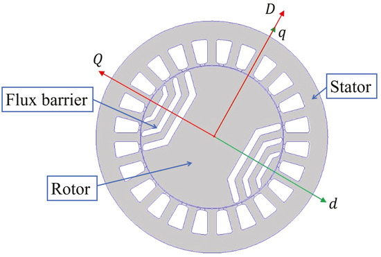
Figure 1.
Comparison between the two-axis rotational reference frame of a pure synchronous reluctance machine and the conventional PM machine frame.
Based on this, the roles of the synchronous inductances are interchanged; consequently, the direct axis aligns with the plunger’s magnetic path that exhibits the lowest reluctance for each pole, as illustrated in Figure 1. Hereafter, the rotational reference frame of the SynR machine is indicated by capital letters D–Q, to clearly differentiate it from that used for the PM machine.
Then, considering a SynR machine, inductances should refer to the D-Q axis reference.
Accordingly, the expression of the saliency ratio should be modified as shown in Equation (1), which, for synchronous reluctance machines, is greater than 1. In fact, synchronous reluctance machines and permanent-magnet-assisted machines are anisotropic because there are magnetic paths with different magnetic permeance values, given by the flux barriers, which build preferential paths for the magnetic linkage flux. Generally, to generate higher torque, anisotropy is needed. In order to get anisotropy, it is convenient to introduce a number of flux barriers, and additive manufacturing can be a very useful technology to produce these intricate geometries, which can become more and more complex when a high number of flux barriers is required.
The expression of the torque for synchronous reluctance machines can be written using the D-Q axis reference. Ideal SynR machines are characterized by infinite permeance on the D axis and infinite reluctance on the Q axis, leading to a torque angle of 90° and a unitary power factor. Nevertheless, in actual practice, a SynR machine has a magnetization current and a flux along the Q axis different from zero.
The D and Q inductances can be split in two terms, the magnetizing inductance and a leakage inductance, as shown in Equation (3).
3. Inductance Computation
To compute the magnetizing inductance on the D axis, the winding function should be introduced. The winding function is a numerical function that can be used to model the machine winding and the air gap. It can be found from the counting function , which depends on the number of wires in the machine.
Applying Ampère’s law to the path reported in Figure 2, the counting function should be used.
where g is the mechanical air gap of the machine.
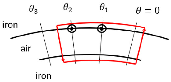
Figure 2.
Example of a flux path.
The magnetic field depends on the considered starting point , which can be found by applying Gauss’s law.
where is the mean value of the counting function. So now, the winding function can be defined as follows:
Thus, the magnetic field can be rewritten using the winding function , which has a mean value equal to zero and does not depend on the starting point.
Once the winding function is defined, it is possible to find the flux along the D axis, from which the expression of the magnetizing inductance can be written. In the proposed approach, a square-wave winding function was considered, as shown in Figure 3.
where is the magnetic induction in the air gap, so by solving the integral and simplifying , the magnetizing inductance on the D axis can be expressed as follows:
where N is the number of turns in series per phase, p is the number of pole pairs, r is the rotor radius, is the stack length, and is Carter’s coefficient.
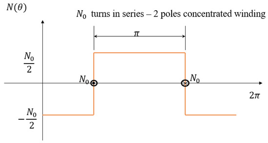
Figure 3.
Square-wave winding function when p = 1.
On the other hand, is given by the sum of two components: a circulating term and a flow-through term.
where comes from the field lines circulating in the rips of the mover’s flux guides, given by the difference between the magnetic potential between the flux barriers, and is obtained from the field lines that cross the flux barriers.
A magnetic circuit model is used in [15,16] for evaluating the Q-axis flux linkage and therefore . Here, a five-flux-barrier tubular machine was taken into account in order to minimize the force ripple generated, according to [17].
Since the magnetic circuit model for a pole pitch is symmetric, only half of the pole pitch are considered to simplify the lumped-parameter model, as shown in Figure 4. The MMF generators represent the Q-axis component of the stator MMF, while the net of permeances stands for the barriers () and air-gap flux tubes corresponding to the flux guides’ ends (). In this simplification, steel is considered as a magnetic short circuit, so there is no MMF drop. Since a regular mover pitch is considered, the air-gap flux tubes and their permeances () are all the same. All the components in the proposed Q-axis magnetic circuit model are normalized with respect to different bases:
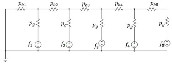
Figure 4.
Lumped-parameter model for reluctance machines.
- For the MMF, the base is its amplitude ;
- For the permeances, the base is ;
- For the magnetic fluxes, the base is .
The MMF generators and are the average values of the sinusoid over the electrical angular span of each mover’s flux guide. The more layers, the more staircase steps; see Figure 5.
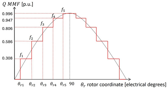
Figure 5.
Q-axis MMF staircase for the definition of MMF generators.
where the values of can be found as follows.
For and 5, where represents the electric angle between two consecutive MMF generators.
The sinusoidal MMF is split into two components, represented in Figure 6:
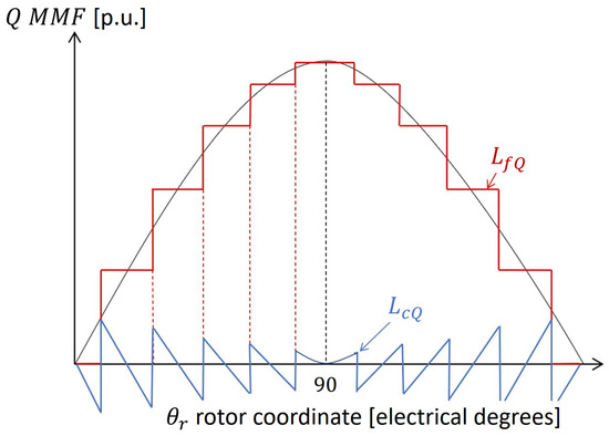
Figure 6.
Stator MMF and its two components.
- The just defined staircase, which is the one that supplies the flow-through flux;
- The residual MMF, given by the difference between the sinusoid and the staircase, which is the one that generates the circulating component.
Assuming a sinusoidal stator MMF and doing some substitutions, the circulating term can be found as follows:
The ratio between and should be as small as possible, and it decreases when the number of layers increases.
Considering the two components of the stator MMF’s sinusoid, represented in Figure 6, the flow-through inductance component can be found:
where is the magnetic potential at node k. It is also possible to write Equation (14) as a function of the air-gap magnetic fluxes, that can be found by solving the magnetic circuit model. In fact, the air-gap magnetic flux can be expressed as follows, and used to rewrite the expression of :
where , in which r is the mover’s radius. The expression found in Equation (14) can be rewritten as follows:
4. Permeance Computation for Tubular Reluctance Machines
The previously presented lumped-parameter model can be adapted to the different configuration of tubular machines with some corrections. Generally speaking, the permeance values can be computed as follows:
where is the permeability of air, A is the area of the section considered, and is the length of the flux path. In the lumped-parameter model considered, everything is per unit; in particular, permeances are per unit of . Referring to the flux barrier k, the value of its permeance per unit can be expressed as follows:
where is the total length of the flux barrier (considering only a half-pole pitch) and is the thickness of the flux barrier. Since the machine considered is tubular, the value of corresponds to the perimeter of the circle with radius the distance between the axis of the machine and the considered point, so this value is not constant in every part of the machine. In order to obtain the same model per unit, a coefficient which considers the reduction in the of the machine should be introduced in the permeances’ computation. As a reference value for , the length of the stack at the air gap is considered, because the air gap is where the electromagnetic phenomenon occurs:
The coefficient states the following relationship between the reference value of the length of the stack and the value considered at the specific point in which the permeance should be computed:
Thus, the computation of the generic permeance per unit becomes:
where is the reference area of the flux barrier considered.
5. Application to a Synchronous Tubular Reluctance Machine
To minimize the force ripple and maximize the thrust force for the chosen configuration, a five-mover-layer machine was taken into account, in accordance with [18]. Since the plunger geometry was obtained by means of additive manufacturing, the material considered for the analysis was the alloy FeCo49V2, a metal powder studied specifically for AM applications.
As the computation of each permeances is equivalent, the complete procedure is reported just for the first one, the external one. The figure below highlights the main considered parameters. The required parameters were measured in reference to the half-pole pitch, as in the magnetic model represented in Figure 4. Axial and longitudinal cross sections of the machine are depicted in Figure 7 and Figure 8, respectively.
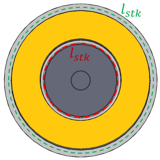
Figure 7.
Section of the motor to highlight the differences between each circumference value.
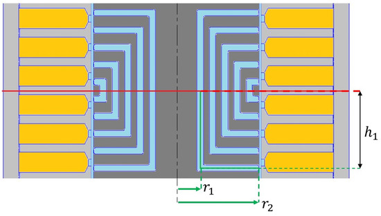
Figure 8.
Main parameters for the permeances’ computation.
The previously described lumped-parameter model was expanded to include the iron located between the end of each flux barrier and the air gap, the stator tooth, and the second air gap at each stator tooth’s end. These elements were added due to mechanical constraints. To accommodate these features, permeances associated with the iron layer were added in parallel to those tied to the flux barriers, while the tooth and gap permeances were placed in series with the air-gap ones, as shown in Figure 9. The newly proposed lumped-parameter model is illustrated in Figure 10. The permeance of the flux barrier was divided into two parts: one for the vertical section and another for the horizontal section. For each section, a coefficient representing the considered barrier’s circumference was calculated, which was crucial for accurately determining the total permeance.
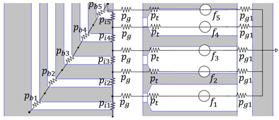
Figure 9.
Half-pole sketch with the new permeances introduced.
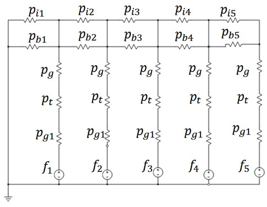
Figure 10.
Lumped-parameter model of the tubular machine.
Initially, end effects were considered but were found not to significantly impact the machine’s overall performance compared to the simulation results. However, including them would greatly complicate the analytical model due to the asymmetry they introduce. Thus, end effects were excluded from the analytical model proposed in this study.
In order to solve the circuit model, first, the total area of the flux barrier was computed. For simplicity, the middle segment of the mover layer was considered, as shown with green lines in Figure 8. Considering the parameters shown in Figure 8, the area can be computed as the sum of two surfaces:
- The first one is the external lateral surface of the cylinder obtained from the revolution of the vertical segment along the axisymmetry axis;
- The second one is the surface given by the circular crown with external radius and internal radius .
Since the two surfaces are different, it is appropriate to split the computation of the permeance into two components, a vertical one, consisting of a cylindrical shape, and a horizontal one, having a ring shape; each of them has a different coefficient for the correct computation of the circumferential length, because they have a different radius.
Each coefficient is computed with respect to a reference circumference, which is the circumference at the air gap. This value is considered as the reference stack length, computed as in Equation (25).
Considering, at first, the vertical segment of length , the vertical coefficient is computed as the ratio between the circumference of radius , which corresponds to the length of the stack at the considered point, and the length of the stack at the air gap taken as reference :
Employing the coefficient , the value of the permeance corresponding to the vertical segment of the flux barrier can be computed:
The same procedure is repeated for the computation of the permeance corresponding to the horizontal segment, for which a new coefficient must be calculated. In this case, the component has a ring shape, so for the computation of the coefficient, the circumference obtained with the medium radius between and should be considered.
where is the radius at the middle point of the horizontal segment considered. The computation of the desired permeance per unit can be carried out, including the corrective coefficient just found.
The corresponding value of reluctance is found from its definition as the inverse of the total permeance, given by the sum of the vertical and the horizontal component, since they are connected in parallel.
The same methodology was applied to determine all the necessary permeances for accurately solving the magnetic model. Additional permeances (and corresponding reluctances) were calculated relative to the original model, as it did not account for the iron situated between each flux barrier and the air gap. Although this iron section had minimal thickness, it did not reach a saturation level that allowed it to be ignored in the proposed model for this machine configuration. Consequently, the permeances of the teeth and the secondary gap between the teeth and the stator yoke were considered. Then, the entire magnetic circuit could be addressed using Kirchhoff’s voltage and current laws to determine the magnetic fluxes and potentials at each node, facilitating the calculation of inductance values along the D and Q axes by applying the equations previously mentioned and adapted for tubular electrical machines. The magnetizing inductance along the D axis could be calculated using Equation (10).
This computation allowed us to obtain a good estimation of the value of when premature saturation of the mover did not occur; on the contrary, an unwanted reduction in was generated and, consequently, an increase in the D-current component occurred. Nevertheless, in tubular electrical machines the mover often saturates at some points because of its geometrical features, since in that case, the mover is reduced to a cylindrical plunger. In order to obtain a better estimation of the inductances, a new coefficient should be introduced, the saturation coefficient , which is obtained as the ratio between the sum of the of all the magnetic paths in the stator and the in the air gap. Each MMF values are computed as the voltage drop in each of the resistors of the lumped parameter model shown in Figure 10.
Thanks to this coefficient, an equivalent magnetic air gap which takes into account saturation phenomena inside the motor can be computed and used to increase the performance of the analytical model. Thus, Equation (10) can be rearranged as shown in Equation (31).
The magnetizing inductance along Q axis can be computed using Equation (11), where the value of the circulating term can be found by applying Equation (13) and the flow-through term using Equation (14). It is important to highlight that the expression in Equation (16) cannot be used in the case of tubular machines, since in that case, the electric angle spanned by two consecutive flux barriers cannot be used to find the air-gap flux when only considering the rotor radius, because the machine is linear. In fact, the definition of the air-gap magnetic flux per unit in the model, reported in Equation (15) for a rotating machine, should be modified according to the tubular configuration, by introducing the correct coefficient which takes into account the gradual decrease in the circumference of the section considered and the fact that the iron has a non-constant thickness in the magnetic path. According to that, the expression found in Equation (16) should be rearranged as shown in the following, by introducing the coefficient and considering the correct dimension concerning the tubular configuration.
Then, the component can be found from the model, according to Equation (17). Then, the slot leakage inductance and the zigzag inductance are computed according to the following equations:
where is the winding factor, is a coefficient which takes into account the shape of the slot (Equation (35)), and is the zigzag coefficient (Equation (36)).
where .
where and are the slot step and the polar step, respectively, and and are the iron widths at the air gap for the stator and the mover, respectively.
Thus, the total inductance value along the D and Q axes can be found as follows:
6. Materials
The FeCo49V2 alloy was chosen for the prototyping test phase. The magnetic properties of the material were evaluated using full ring samples with a Brockhaus MPG 200 system.
Comprehensive information on the measurements and the experimental setup can be found in [19]. The findings, shown in Figure 11, were incorporated into the 2D-FEA software (FEMM 4.2) to conduct simulations with the final material. The annealing process significantly enhanced the alloy’s magnetic capabilities, achieving saturation similar to that of conventional FeCo lamination stock. The sample in its initial state had a lower initial slope, indicating reduced initial permeability, whereas the heat-treated sample presented a steeper initial slope, reflecting a marked improvement in initial permeability. The BH curve of the annealed FeCo49V2 sample was employed for the simulations.
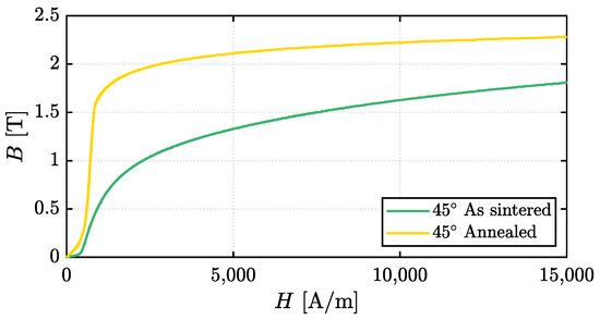
Figure 11.
BH curve of FeCo49V2 sample: as sintered (green line) and after annealing (yellow line).
After heat treatment, both tensile and yield strength decreased, with tensile strength falling to 250–280 N/mm2 and yield strength to 290–330 N/mm2. This reduction was due to the relaxation of internal stresses during the heat treatment process and to the larger grain size that reduced the strengthening between grain boundaries.
In addition, the as-built sample showed elongation values between 5% and 20%, indicating moderate ductility. However, the heat-treated sample was characterized by a reduced elongation range of 2% to 15%, signifying a loss in ductility that could be attributed to embrittlement mechanisms, grain boundary weakening, and/or the precipitation of brittle phases during heat treatment.
In our case, the purpose was to maximize the magnetic performance of the alloy, so the annealing process was chosen accordingly. The authors in [20] show various annealing strategy that can improve the mechanical properties of an additively manufactured metal alloy. Depending on the application, it is essential to find the correct annealing procedure that can grant a careful balance among desired properties.
7. Comparison with Simulation Results
To verify the accuracy of the proposed model, the obtained results were compared with 2D FEA simulation results from Matlab’s FEMM toolbox. Simulations were performed by considering a current density of 7.5 . The AM material considered for the mover was a metal powder of FeCo49V2. Although this powder shows promising magnetic properties, current research is mainly aimed at enhancing its mechanical performance and lowering internal residual stresses, which may negatively affect its magnetic behavior.
The motor parameters considered for the simulations are reported in Table 1.

Table 1.
Machine dimensions and parameters.
In [10], a comparison of the performance of the machine obtained when considering a traditional laminated material and an AM material is presented, showing a slight decrease in the thrust force with the proposed solution. Nevertheless, the solution with a traditionally laminated material was not feasible for this configuration, so this slight loss in performance was acceptable. As shown in Figure 12, a thrust force of 62.95 N was obtained from the load simulation. Figure 13 shows the mesh used for the analysis together with the visualization of the flux lines and flux density of the machine obtained in the 2D FEA post-processor. Due to the tubular configuration, the mover was brought to saturation more easily than in conventional rotating machines. Hence, saturation is a phenomenon which must be taken into account in the analytical design phase.
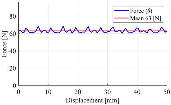
Figure 12.
Thrust force obtained with 2D FEA simulations.
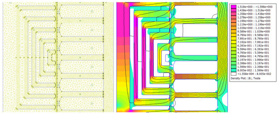
Figure 13.
Two-dimensional FEA mesh (on the left) and post-processor (on the right).
Considering the equality between electrical and mechanical power, an analytical expression of the thrust force produced by the tubular machine can be obtained:
where v is the linear velocity of the machine, m is the number of phases, E is the electromotive force, and I is the total current. Hence, the thrust force can be expressed as follows:
where is the polar pitch.
The value of the inductance value along the D axis decreased with the increase in current density. However, was first estimated with Equation (10), which considers only the potential drop in the air gap and neglects the one in the iron. This is correct only for low values of j because, when the mover saturates, the potential drop in the mover’s iron causes a reduction in and cannot be neglected. This phenomenon can be represented by adding the saturation coefficient , according to Equation (31). Figure 14 shows the trend in the inductances along the D and Q axes, comparing the estimation using 2D FEA simulations against the analytical model results. According to the comparison of analytical and 2D FEA results, neglecting the end effects did not significantly affect the analytical model.
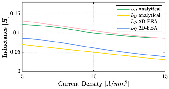
Figure 14.
Inductances along D and Q axes obtained with 2D FEA simulations and analytical model.
The leakage inductance component was included in both the computed values for and . It is important to notice that in the computation of the total leakage inductance reported in Equation (37), the belt inductance was neglected. However, with the increasing saturation level of the machine, this component can become an important factor, causing a different increment in D-axis and Q-axis leakage inductances, as shown in the different FFT of the flux density in the gap computed for the D and Q axes (Figure 15 and Figure 16, respectively).
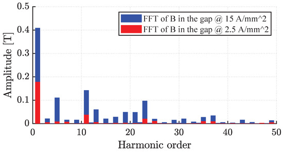
Figure 15.
FFT of the flux density in the gap comparison at and 15 A/mm2 (D axis).
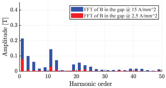
Figure 16.
FFT of the flux density in the gap comparison at and 15 A/mm2 (Q axis).
8. Metal Additive Manufacturing Feasibility Validation
To assess the feasibility of producing the proposed plunger design, a segment of the mover’s pole pitch was fabricated using a 3D printing technique with a mild steel powder. The printed model incorporated a 270° cutaway for direct examination and evaluation of the internal layout of the flux barriers. Despite the slim flux barrier thickness of 0.9 mm, the design was manufacturable via Selective Laser Melting (SLM), which yielded well-defined barriers. SLM is a metal additive process that uses a moving laser beam to melt metal powder layer by layer, creating solid cross sections of the part. This method is prevalently used in the fabrication of electrical machine components, as it produces parts with an enhanced density and microstructure in contrast to sintering. The distinct consolidation process results in improved mechanical properties compared to traditional methods for the same material [21]. As depicted in Figure 17a, an example of a 3D-printed mover pole is illustrated, wherein the rib thickness was increased from 0.1 mm to 0.5 mm. Figure 17b showcases the full mover prototype. Two identical prototypes were produced through 3D printing, with one cut along its longitudinal axis to scrutinize the printing quality. A machining allowance of 0.5 mm was factored in. However, challenges in printing the entire geometry can occur if the component is not angled at 45° during the additively manufactured process, due to perpendicular features to the build direction, necessitating additional support within the flux barriers for the full-length mover. These supports could be straightforward wall structures or more sophisticated designs, which can help minimizing eddy current losses. To facilitate the full geometry’s printing, a manufacturability-oriented redesign was imperative. Drain holes were incorporated at the flux barriers’ termini at 120° intervals—totaling six per circlet. For the 270 printed mock-up, they were not necessary, but they can be seen in the picture shown in Figure 17b). The rib thickness was adjusted from 0.2 mm to 0.7 mm to offer a 0.5 mm allowance for machining. This machining allowance is critical for meeting post-processing needs due to surface and cylindricity demands. The four-pole configuration, importantly, can still be sintered at a 45° angle without needing internal supports.
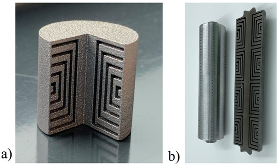
Figure 17.
Sample of 3D-printed mover: one pole in Fe-545 (a) and the complete mover geometry in FeCo49V2 (b).
As highlighted in [21,22], printing a non-laminated, solid conducting material for components in electrical machines leads to increased iron losses, due to the enhanced generation of eddy currents and hysteresis losses. To minimize these losses in the mover, it is possible to adopt more complex internal structures that introduce gaps within the material. Various design strategies suitable for metal additive manufacturing are available, such as Hilbert structures or mesh-type geometries. Nevertheless, a careful trade-off must be achieved between reducing iron losses and ensuring the sufficient mechanical strength of the component to undergo the annealing process with minimal distortion and to allow for the machining to final dimensions.
9. Experimental Results
A prototype of the motor (see Figure 18 and Figure 19) was built to validate some of the results obtained analytically and through 2D FEA simulations. The stator was constructed using stacked lamination rings housed in a tubular outer shell, and the coil terminals were left unconnected to allow a flexible interconnection for testing and parameter measurement. Initially, the phase winding resistance was measured, yielding a value of 2.69 Ω, which matched the value obtained through analytical calculations.
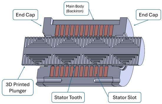
Figure 18.
Complete CAD 3D rendering of the proposed tubular machine.
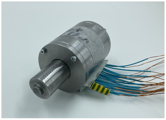
Figure 19.
Fabricated linear motor prototype.
Experimental measurements were performed employing an LCR meter at 50 Hz with the bias current provided by the LCR meter. The 2D FEA simulations were performed under the same powering conditions as a comparison.
At first, the leakage inductance associated with a single stator slot was measured. A value of 811 mH was obtained from the 2D FEA simulations (see Figure 20), while experimental measurements on the prototype yielded a value of 813 mH. The analytical results also showed good agreement with both the 2D FEA and experimental values.
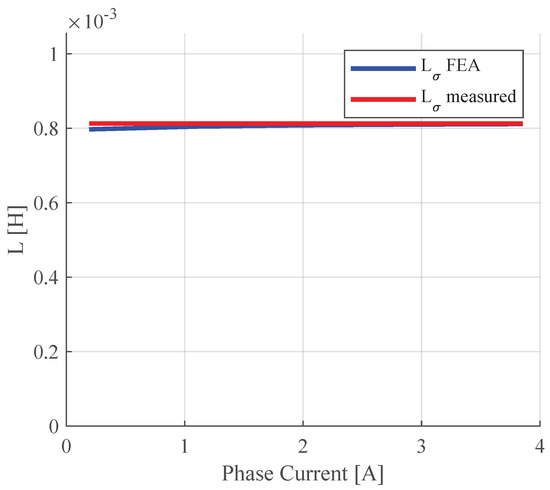
Figure 20.
Two-dimensional FEA and measured of one stator slot.
The mover was manufactured through metal powder bed fusion using FeCo49V2 powder. It was printed with a building direction of 45 degrees. After the printing process, the mover was annealed to improve the magnetic properties of the material.
The complete annealing cycle, described in [23,24], consisted in the following:
- Pre-annealing at 700 °C for two hours;
- Annealing at 820 °C for ten hours.
The two-stage approach optimized the microstructure for improved magnetic performance and allowed one to achieve a more uniform and larger grain size which is known to be beneficial for reducing hysteresis losses and increasing permeability (further results are reported in [19]).
Additional measurements including the mover were made. As shown in Figure 21, the single-phase inductance value was slightly lower than the one obtained via 2D FEA simulations, about 0.2 mH less. It is worth noticing that the saliency ratio for the simulated machine and the prototype was nearly the same, equal to 1.12 for the prototype and 1.1 in simulations. In Figure 18, the complete 3D geometry of the prototype is shown.
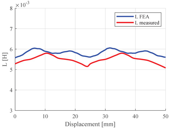
Figure 21.
Phase inductance obtained via 2D FEA and measured on the prototype.
10. Conclusions
In this paper, the lumped-parameter model of a pure synchronous reluctance tubular linear machine was presented. The analytical equations for rotating machines were adapted to linear tubular machines. The complex shapes of the flux barriers, difficult to obtain by conventional manufacturing techniques, can be realized by means of metal additive manufacturing. This model can be used to obtain a first estimation of the expected performance of a machine in terms of thrust force. The results obtained analytically were compared with 2D finite-element simulations’ results in order to verify the accuracy of the proposed model. A good correspondence was found between simulations’ results and the analytical model over a broad range of current values and especially at low currents, thanks to the introduction of the saturation coefficient in the computation of . In addition, some considerations relating to the re-design process for the manufacturing of the innovative geometry were given, and the first results from a prototype were presented. The measured quantities were in good agreement with the results obtained via 2D FEA and analytical computations when the mover was neglected. The inductance values measured with the mover inserted were slightly lower than the computed ones. Nevertheless, the saliency ratio was nearly the same.
Author Contributions
Conceptualization, G.S. and C.B.; validation, N.G., C.B., and F.I.; writing—original draft preparation, G.S. and N.G.; writing—review and editing, M.V. and F.I. All authors have read and agreed to the published version of the manuscript.
Funding
This research received no external funding.
Data Availability Statement
The original contributions presented in this study are included in the article. Further inquiries can be directed to the corresponding author.
Conflicts of Interest
The authors declare no conflicts of interest.
References
- Wang, J.; Jewell, G.; Howe, D. A general framework for the analysis and design of tubular linear permanent magnet machines. IEEE Trans. Magn. 1999, 35, 1986–2000. [Google Scholar] [CrossRef]
- Commins, P.A.; Moscrop, J.W.; Cook, C.D. Synchronous reluctance tubular linear motor for high precision applications. In Proceedings of the 2015 Australasian Universities Power Engineering Conference (AUPEC), Wollongong, NSW, Australia, 27–30 September 2015; pp. 1–6. [Google Scholar] [CrossRef]
- Tomczuk, B.; Sobol, M. Field Analysis of the Magnetic Systems for Tubular Linear Reluctance Motors. IEEE Trans. Magn. 2005, 41, 1300–1305. [Google Scholar] [CrossRef]
- Popa, D.C.; Micu, D.D.; Miron, O.R.; Szabó, L. Optimized Design of a Novel Modular Tubular Transverse Flux Reluctance Machine. IEEE Trans. Magn. 2013, 49, 5533–5542. [Google Scholar] [CrossRef]
- Bianchi, N.; Bolognani, S.; Corda, J. Tubular linear motors: A comparison of brushless PM and SR motors. In Proceedings of the 2002 International Conference on Power Electronics, Machines and Drives (Conf. Publ. No. 487), Bath, UK, 16–18 April 2002; pp. 626–631. [Google Scholar] [CrossRef]
- Donaghy-Spargo, C. Synchronous reluctance motor technology: Industrial opportunities, challenges and future direction. Eng. Technol. Ref. 2016, 2016, 1–15. [Google Scholar] [CrossRef]
- Bailey, G.; Mancheri, N.; Van Acker, K. Sustainability of Permanent Rare Earth Magnet Motors in (H)EV Industry. J. Sustain. Metall. 2017, 3, 611–626. [Google Scholar] [CrossRef]
- Murataliyev, M.; Degano, M.; Di Nardo, M.; Bianchi, N.; Gerada, C. Synchronous Reluctance Machines: A Comprehensive Review and Technology Comparison. Proc. IEEE 2022, 110, 382–399. [Google Scholar] [CrossRef]
- Pellegrino, G.; Jahns, T.; Bianchi, N.; Soong, W.; Cupertino, F. The Rediscovery of Synchronous Reluctance and Ferrite Permanent Magnet Motors; SpringerBriefs in Electrical and Computer Engineering; Springer: Berlin/Heidelberg, Germany, 2016; VIII, 136p. [Google Scholar] [CrossRef]
- Bianchini, C.; Sala, G.; Torreggiani, A.; Giannotta, N.; Davoli, M.; Macrelli, E.; Immovilli, F.; Bellini, A. Synchronous Reluctance Tubular Machine by Means of Additive Manufacturing. In Proceedings of the 2022 International Conference on Electrical Machines (ICEM), Valencia, Spain, 5–8 September 2022. [Google Scholar]
- Hong, H.S.; Liu, H.C.; Cho, S.Y.; Lee, J.; Jin, C.S. Design of High-End Synchronous Reluctance Motor Using 3-D Printing Technology. IEEE Trans. Magn. 2017, 53, 8201705. [Google Scholar] [CrossRef]
- Tiismus, H.; Kallaste, A.; Vaimann, T.; Rassõlkin, A. State of the art of additively manufactured electromagnetic materials for topology optimized electrical machines. Addit. Manuf. 2022, 55, 102778. [Google Scholar] [CrossRef]
- Naseer, M.U.; Kallaste, A.; Asad, B.; Vaimann, T.; Rassõlkin, A. A Review on Additive Manufacturing Possibilities for Electrical Machines. Energies 2021, 14, 1940. [Google Scholar] [CrossRef]
- Wrobel, R.; Mecrow, B. A Comprehensive Review of Additive Manufacturing in Construction of Electrical Machines. IEEE Trans. Energy Convers. 2020, 35, 1054–1064. [Google Scholar] [CrossRef]
- Vagati, A.; Franceschini, G.; Maongiu, I.; Troglia, G. Design Criteria of High Performance Synchronous Reluctance Motors. In Proceedings of the Conference Record of the 1992 IEEE Industry Applications Society Annual Meeting, Houston, TX, USA, 4–9 October 1992. [Google Scholar]
- Vagati, A.; Boazzo, B.; Guglielmi, P.; Pellegrino, G. Ferrite Assisted Synchronous Reluctance Machines: A General Approach. In Proceedings of the 2012 XXth International Conference on Electrical Machines, Marseille, France, 2–5 September 2012. [Google Scholar]
- Ferrari, S.; Pelegrino, G.; Davoli, M.; Bianchini, C. Reduction of Torque Ripple in Synchronous Reluctance Machines through Flux Barrier Shift. In Proceedings of the 2018 XIII International Conference on Electrical Machines (ICEM), Alexandroupoli, Greece, 3–6 September 2018. [Google Scholar]
- Vagati, A.; Pastorelli, M.; Franceschini, G.; Petrache, S.C. Design of Low-Torque-Ripple Synchronous Reluctance Motors. IEEE Trans. Ind. Appl. 1998, 34, 758–765. [Google Scholar] [CrossRef]
- Giannotta, N.; Sala, G.; Puccio, G.; Kallenbach, B.; Bianchini, C.; Nuzzo, S. Effect of Annealing and Building Direction on the Magnetic Behavior of Additively Manufactured FeCo49V2 Alloy. In Proceedings of the 2025 Workshop on Electrical Machines, Design, Control and Diagnosis (WEMDCD), Valletta, Malta, 9–10 April 2025. [Google Scholar]
- Lin, D.; Xu, L.; Jing, H.; Han, Y.; Zhao, L.; Minami, F. Effects of annealing on the structure and mechanical properties of FeCoCrNi high-entropy alloy fabricated via selective laser melting. Addit. Manuf. 2020, 32, 101058. [Google Scholar] [CrossRef]
- Giannotta, N.; Sala, G.; Bianchini, C.; Torreggiani, A. A Review of Additive Manufacturing of Soft Magnetic Materials in Electrical Machines. Machines 2023, 11, 702. [Google Scholar] [CrossRef]
- Plotkowski, A.; Pries, J.; List, F.; Nandwana, P.; Stump, B.; Carver, K.; Dehoff, R. Influence of scan pattern and geometry on the microstructure and soft-magnetic performance of additively manufactured Fe-Si. Addit. Manuf. 2019, 29, 100781. [Google Scholar] [CrossRef]
- Lindroos, T.; Riipinen, T.; Metsä-Kortelainen, S.; Pippuri-Mäkeläinen, J.; Manninen, A. Lessons learnt-additive manufacturing of iron cobalt based soft magnetic materials. J. Magn. Magn. Mater. 2022, 563, 169977. [Google Scholar] [CrossRef]
- Riipinen, T.; Metsä-Kortelainen, S.; Lindroos, T.; Keränen, J.; Manninen, A.; Pippuri-Mäkeläinen, J. Properties of soft magnetic Fe-Co-V alloy produced by laser powder bed fusion. Rapid Prototyp. J. 2019, 25, 699–707. [Google Scholar] [CrossRef]
Disclaimer/Publisher’s Note: The statements, opinions and data contained in all publications are solely those of the individual author(s) and contributor(s) and not of MDPI and/or the editor(s). MDPI and/or the editor(s) disclaim responsibility for any injury to people or property resulting from any ideas, methods, instructions or products referred to in the content. |
© 2025 by the authors. Licensee MDPI, Basel, Switzerland. This article is an open access article distributed under the terms and conditions of the Creative Commons Attribution (CC BY) license (https://creativecommons.org/licenses/by/4.0/).