1. Introduction
Joint motors, the core components in the rapidly growing robotics industry field, have gathered significant attention [
1,
2]. Contemporary advancements in joint motor design necessitate enhanced output torque, increased power density, and improved reliability [
3,
4]. With enhanced fault-tolerant performance and higher power density compared with the traditional three phase PMSM [
5], multi-phase permanent magnet synchronous motors attract increasing interest. In the meantime, pursuing higher output power increases the likelihood of faults in power switch devices [
6]. Studies [
7] attribute 38% of motor faults in variable-speed ac drives to the power switch failure. Instantaneous overcurrent typically causes switch failures [
8], leading protection protocols to disable the faulty bridge arm and induce open-phase faults. Consequently, fault-tolerant control (FTC) for multiphase motors is critical. To improve the fault-tolerant performance, various fault-tolerant control (FTC) methods of open-phase-fault strategies have been proposed.
In the study of open-phase faults, the common optimized target is the reduction in output torque ripple. In the early applications, a simple approach to maintain the smooth output torque is to deactivate the faulted three-phase [
9]. With the remaining healthy three-phase winding set, the motor is able to maintain the torque output in low load, but the maximum output torque capability is reduced by half. In the recent studies, the mainstream method to maintain the torque capability is to fully use all the remaining healthy windings, and various control strategies are proposed. In [
10], an improved direct torque control (DTC) based on virtual vector is proposed for a five phase induction motor. The space vector is reconstructed under open-phase-fault. Then a modified lookup table is designed to improve the fault-tolerant performance. In the study of [
11], virtual vector-DTC and rotor-field-oriented control are compared in a five phase induction motor, and the obtained results show that the virtual vector-DTC has a lower capability of maximum torque and higher harmonic phase current content than rotor field-oriented control (RFOC). In [
12,
13], an adaptive fault control and diagnosis strategy is proposed for dual three-phase PMSM (DTP-PMSM). This work resolves the conflict between the x-y current closed-loop control and the desired after-fault x-y current control. To tackle this problem, x-y reference is updated by a half-sine phase locked loop to generate smooth output torque under open -phase fault without diagnosis. Ref. [
14] proposed a deadbeat-predictive-current-control-based FTC strategy combined with a T type three level inverter for DTP-PMSM. This paper introduced the voltage vector in T type three level inverter, and proposed multi-FTC strategies for different fault types, including open switch and open-phase fault. In [
15,
16], different maximum torque per ampere (MTPA) control strategies are proposed to enhance the output torque capability.
Beyond torque ripple, copper loss minimization is equally critical. Due to the absence of faulty phase, the output power is supported by the remaining healthy phase, which leads to higher copper loss [
17]. Under a heavy load condition, the increased copper loss may break the heat balance and leads to overheating [
18]. In [
19], current references are derived for the minimized copper loss control for DTP-PMSM under open-phase fault. However, the sinusoidal phase current condition reduces the optimization level of copper loss. Ref. [
20] proposed a FTC scheme with full range minimum-loss under open phase for DTP PMSM. The reference x-y current is derived from the trajectories of torque and harmonic subspace under open-phase fault and this control method is equipped with adaptive fault-tolerant capability. Nevertheless, the optimization is yet limited by the sinusoidal current, leading to incomplete copper loss reduction. In [
21], the harmonic disturbance induced by open-phase fault and dead time in torque and harmonic subspace are extensively studied. By redesigning the loop controller, copper loss is reduced by suppressing the harmonic current. Though, the harmonic-induced copper loss is minimized, the sinusoidal current does not reach the optimal minimized copper loss condition. In [
22], by controlling the copper loss power rate to minimum, the copper loss of DTP-PMSM is further optimized. However, the introduced zero-sequence current (ZSC) in connected neutral point DTP-PMSM causes torque ripple and degrades the operation performance [
23].
As among the most popular multi-phase motors [
24], DTP-PMSMs are classified into phase-shift type and non-phase-shift type according to the spatial distribution of two winding sets. For phase-shift DTP-PMSM (PSDTP-PMSM), low impedance in the 5th and 7th harmonic loop leads to the heavy harmonic disturbance. Thus, in the common control framework for PSDTP-PMSM, vector space decomposition method (VSD) [
25] is applied to decouple variables into torque subspace and harmonic subspace. However, the non-phase-shift DTP-PMSM (NPSDTP-PMSM) has no such impedance characteristic. Dual independent current control (DICC) is widely applied for NPSDTP-PMSM, considering the two sets of windings as two independent virtual motors [
26]. Compared with the VSD method, DICC offers lower complexity and reduces the controller’s computational burden.
However, the current studies focus on single open-phase fault (SOPF), and few studies on dual open-phase fault (DOPF) are conducted. In addition, current methods on torque ripple reduction are through DTC or harmonic tracking by VSD [
9,
10,
11,
12,
13,
14,
15,
16], and copper loss optimization remains limited by sinusoidal current constraints [
19,
20,
21,
22] and ZSC complications [
23]. These existing FTC methods prioritize PSDTP-PMSMs using VSD control. Despite simpler DICC implementation, NPSDTP-PMSMs lack dedicated FTC strategies.
This paper bridges this gap by proposing a novel FTC strategy for NPSDTP-PMSMs that simultaneously minimizes copper loss and torque ripple under SOPF and DOPF. This work presents three key advances:
- (1)
Analytical proof of the ZSC self-suppressing mechanism in NPSDTP-PMSMs and immunity to ZSC-induced torque ripple;
- (2)
A copper-loss-optimized FTC strategy for SOPF and DOPF leveraging the advantages in (1);
- (3)
Experimental validation on a robotic integrated motor drive (IMD) platform.
The rest of the content of this paper is organized as follows. The mathematical model of NPSDTP-PMSM and zero-sequence loop analysis are presented in
Section 2. Then, in
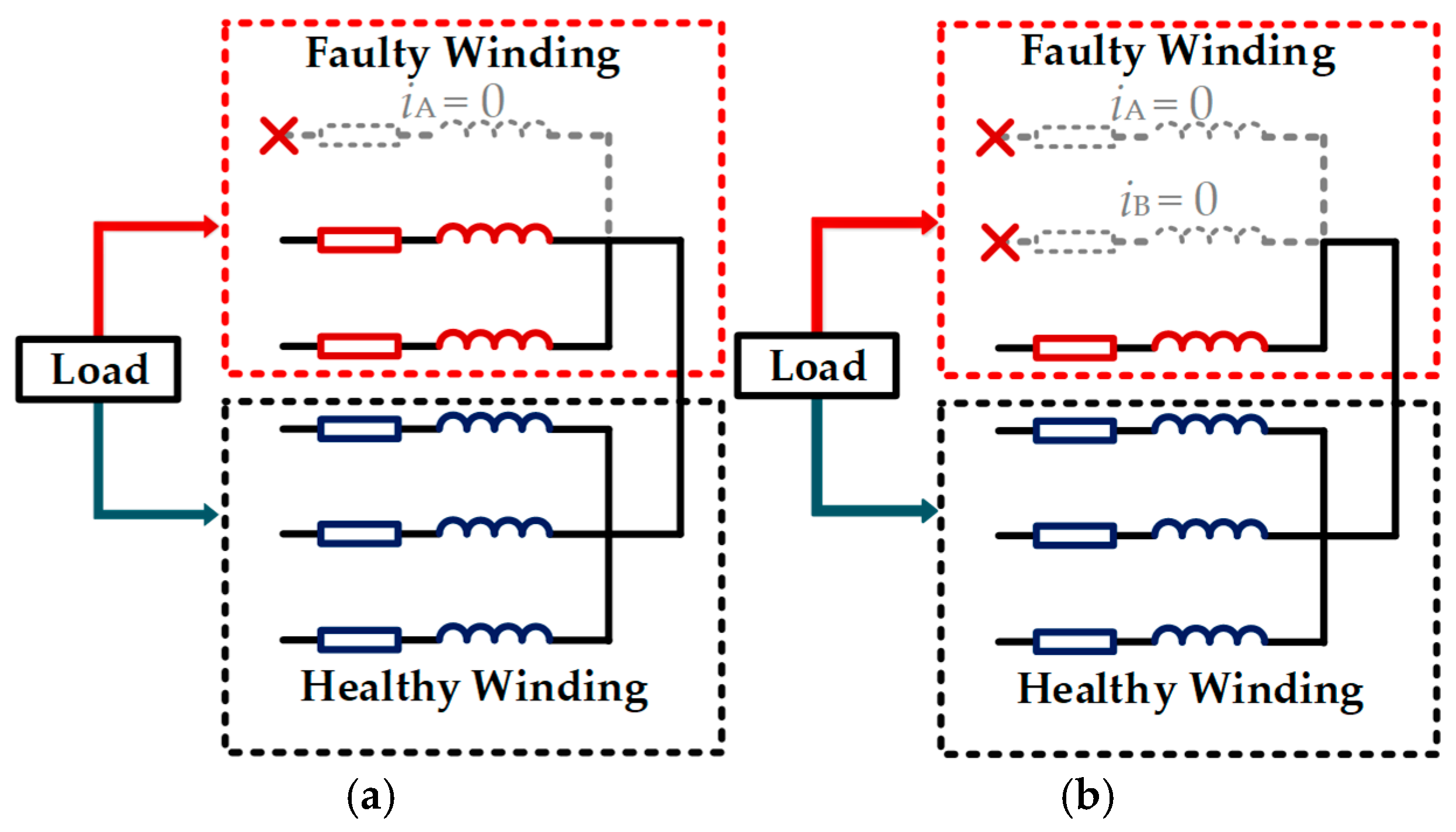
Section 3, the copper loss model of NPSDTP-PMSM is derived and maximum-constraint-free conditions are constructed for single and dual open-phase fault in one winding set, and the proposed FTC strategy is established. In
Section 4, the proposed FTC strategy is performed on a joint IMD platform and experimental results validate the proposed method. Finally, the conclusions of this paper are drawn in
Section 5.
2. Mathematical Model of NPSDTP-PMSM
DTP-PMSMs are classified into two types: connected neutral point and isolated neutral point. The difference is the zero-sequence loop (ZSL) is blocked in the isolated neutral point type but remains unblocked in the connected type. ZSL provides an additional control dimension for enhanced FTC performance. However, the induced ZSC causes more power loss in healthy condition. In this section, the general model of DTP-PMSM with connected neutral point is established. Based on which, ZSC self-suppressing mechanism and immunity to ZSC-induced torque ripple in NPSDTP-PMSM are extensively analyzed.
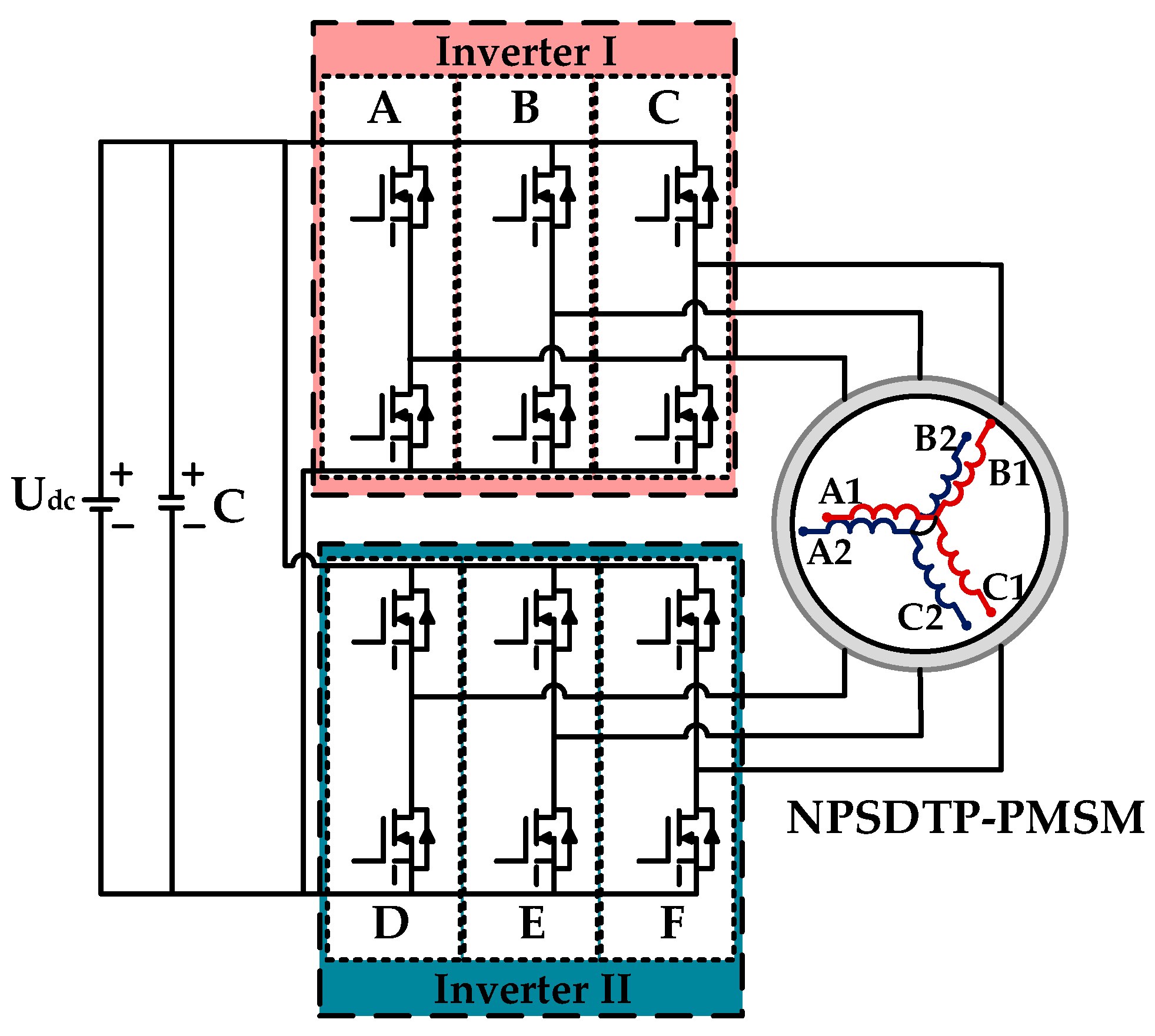
NPSDTP-PMSMs have two sets of windings fed by two inverters connected to the same DC power, as shown in
Figure 1. The two winding sets have no spatial phase shift. In the stationary coordinate, named as ABC-axis, the phase voltage, flux linkage and torque equations can be written as
where
us is the phase voltage vector,
is the phase current vector,
is the linkage flux vector,
Rs is the stator resistance,
Ls is the inductance matrix, and
is the permanent magnet flux linkage matrix.
Te is the electromagnetic torque.
np is the pole pair number.
In the ZSL, the harmonics of permanent magnet flux linkage should be considered. Since the 3rd-harmonic is the main content, the permanent magnet flux linkages can be written as
where
ψf1 is amplitude of fundamental permanent magnet flux linkage,
ψf3 is amplitude of the 3rd-harmonic permanent magnet flux linkage, and
θe is the electrical angle.
The variables under
A-B-C axis are strongly coupled, making the analysis difficult. Applying coordinate transformation (5) to (1) yields voltage equations in the synchronous
d-q-z axis. It should be noted that to shorten the end of stator for the limited space, common joint motors adopt concentrated winding configuration. The mutual inductance between two sets of windings is small and can be neglected in the modeling. Thus, the voltage equations and electromagnetic torque in
d-q-z axis can be written as
where
udx,
uqx, and
uzx are the
d-q-z voltage.
idx,
iqx, and
izx are the
d-q-z axis current.
ψdx,
ψqx, and
ψzx represent the
d-q-z axis flux linkage, and e
3x is the 3rd-harmonic back electromotive force (3rd BMF). The subscript represents the winding set. And
Ld,
Lq, and
Lz are the
d-axis,
q-axis, and zero-axis inductance separately.
From (6), in DTP-PMSM, the two winding sets have independent
d-q axis variables but share the same current path in
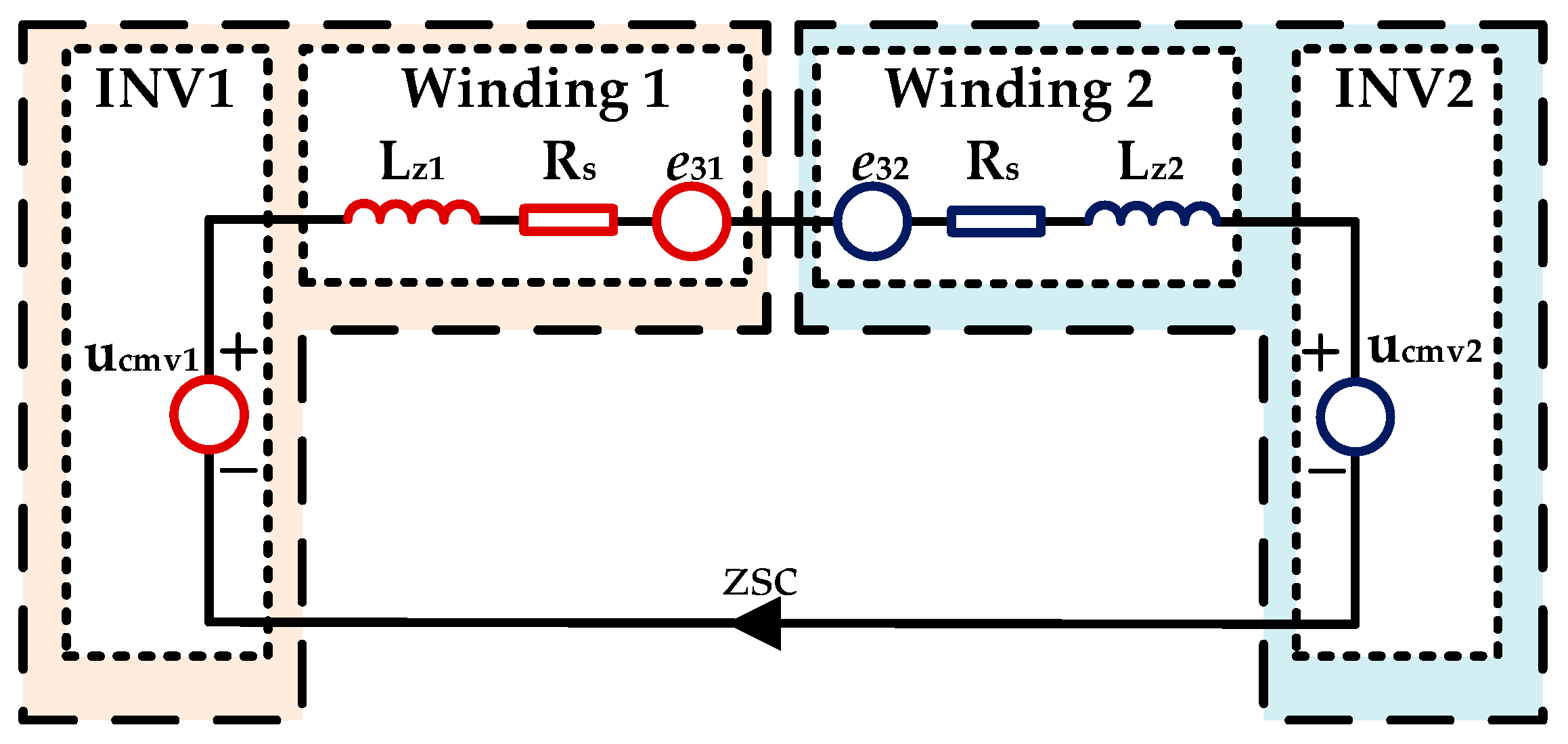
z-axis. Consequently, the ZSL becomes the sole coupling path. The ZSC of each winding set has the connection of
iz =
iz1 = −
iz2. Thus, the ZSL is illustrated in
Figure 2, which consists of common-mode voltage (CMV) from each inverter, zero-sequence inductance and resistance, and the 3rd BEMF from each winding set. Then the voltage equation can be written as
The key difference between PSDTP-PMSM and NPSDTP-PMSM lies in the phase shift angle between two winding sets. Under healthy condition, ZSC in PSDTP-PMSM causes torque ripple and additional copper loss, shown in (8), where
e31iz1+
e31iz1 ≠ 0. Thus, high bandwidth current controller is required to suppress the ZSC. Moreover, the existence of 3rd BEMF, being an AC component, requires high-bandwidth ZSC controllers [
27]. However, in NPSDTP-PMSMs, the symmetric spatial and electrical characteristics inherently suppress ZSC: CMVs and the 3rd BMFs mutually counteract between winding sets. Critically, ZSC induces zero torque ripple for harmonic torques cancel out
e31iz1+
e31iz1 = 0. Consequently, under fault-tolerant operation, ZSC can be actively regulated without concern of inducing torque ripple. Moreover, due to the cancellation of 3rd BMF harmonics, the ZSL behaves as a purely resistive-inductive (R-L) load, simplifying ZSC controller design to a standard RL load regulation problem. Theoretically, these properties grant NPSDTP-PMSMs superior current and torque performance under both healthy and fault conditions.
The control framework of NPSDTP-PMSM is shown in
Figure 3. In the DICC strategy, NPSDTP-PMSM is considered as two separate virtual motors with the same rotor position, and each virtual motor is controlled by individual current loops in
d-q-z axis. In the z axis, ZSC is controlled by regulating the CMVs from two inverters. To avoid the disturbance on effective voltage vector, 000 and 111 voltage vectors are used for the regulation. Moreover, to reduce the influence of scattered signal error, the average of ZSC from two winding sets is adopted and a PI regulator with saturation of 0–1 is implemented in the
z-axis closed-up current control.
4. Experimental Verification
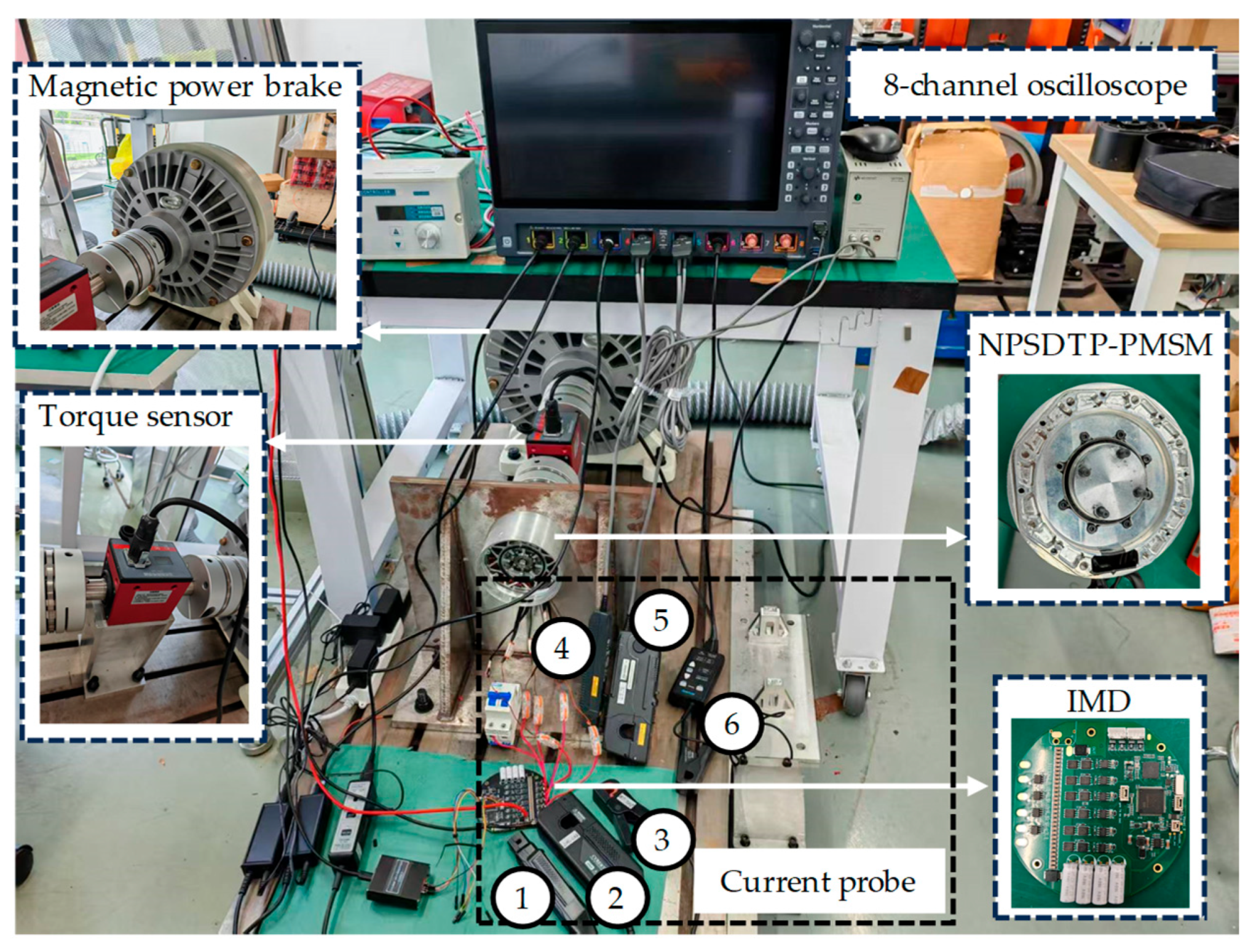
Experiments were conducted on a joint motor powered by an integrated machine drive (IMD). The experiment platform is shown in
Figure 7. The key parameters of the joint motor are listed in
Table 1. In the IMD, the MCU (GD32F470VGT6) and the drive circuit are on the same PCB board. The proposed FTC algorithm is performed by MCU. PWM signals are sent to the gate-driver IC. The on-board magnetic encoder comprises two magnetic sensors with 90° phase shifted, where the magnetic ring is sensed. In the experiment, a magnetic powder brake (MPB) is adopted as the load. By adjusting the input current of MPB, the load torque can be adjusted. Open-phase faults were emulated by disconnecting phases via air switches. In the experiment, the control performance is decided by the current traction. Thus, the actual and reference currents in
d-q-z axis are collected and transmitted to computer, where a high speed universal asynchronous receiver/transmitter (UART) with 6M bps is used to improve the data quality. Moreover, to precisely calculate the copper loss, 6 current probes are used for the phase current and Data was recorded via an 8-channel oscilloscope.
All the experiments are carried out under 30 Nm load and 24 rpm speed. To simplify the description, winding set of ABC and DEF are named as M0 and M1. The initial d-z axis current references of M0 and M1 are zero, and q axis current reference is equally dispatched. In SOPF, phase D is disconnected, and in DOPF, phase D and E are blocked. Furthermore, consistent with the Nyquist-Shannon sampling theorem, signal components exceeding 25 kHz (where fs = 50 kHz) are inherently attenuated and thus omitted from analysis. This 50 kHz sampling configuration remains invariant for all operational scenarios during oscilloscope measurements.
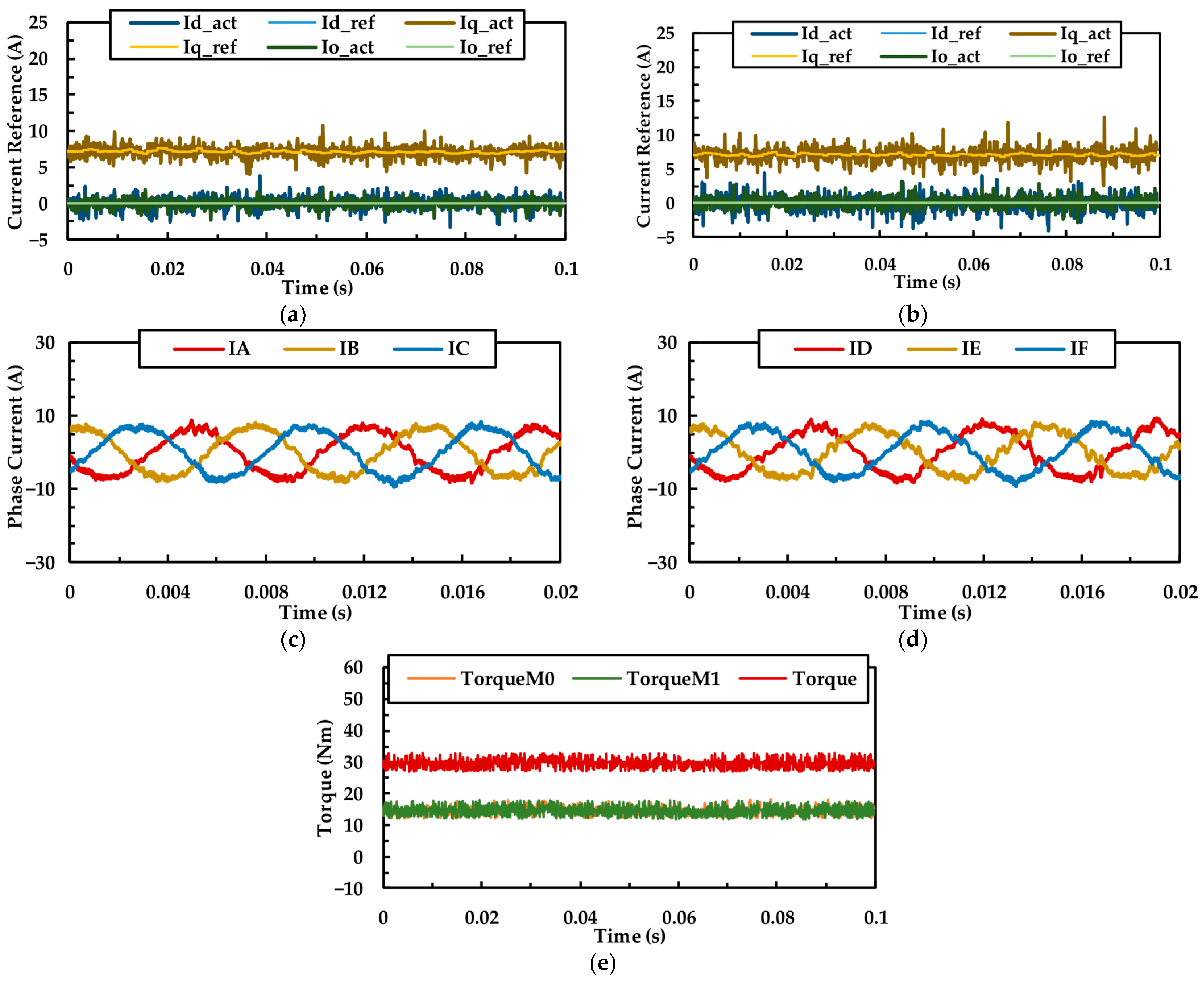
The steady-state performance of the NPSDTP-PMSM joint motor under healthy condition is shown in
Figure 8. In
Figure 8a,b,e, the
d-q-z current references of M0 and M1 are the same, and the load torque is equally allocated to each winding set. For the same electrical phase, mutual cancellation of CMVs and 3rd BEMFs between winding sets minimizes ZSC.
Figure 9 shows the performance of NPSDTP-PMSM under SOPF with no FTC strategy. From
Figure 9a,b, in
d-q axis, M0 is capable of tracking the current references and generates steady output torque. However, with two phases remaining, M1 fails to track reference commands, and the 2nd order frequency ripple occurs in the
d-q currents and fundamental frequency ripple is induced in the
z-axis. In
Figure 9e, the output torque of NPSDTP-PMSM manifests 2nd order frequency torque ripple under single-open-phase fault.
In
Figure 9c,d, for the additional current path in ZSL, fundamental currents of phase E and F can be regulated independently instead of forming a single-phase loop. ZSL enables continuous torque production in the faulted set (M1) by independent phase E/F current regulation. Moreover, the load torque is still equally allocated to M0 and M1, and the average
q axis current of M1 is equal to the reference. This characteristic shows the outstanding fault-tolerant performance of NPSDTP-PMSM with connected neutral point. However, the 2nd order frequency torque ripple brings vibration and noise, which is vital in the joint motor applications.
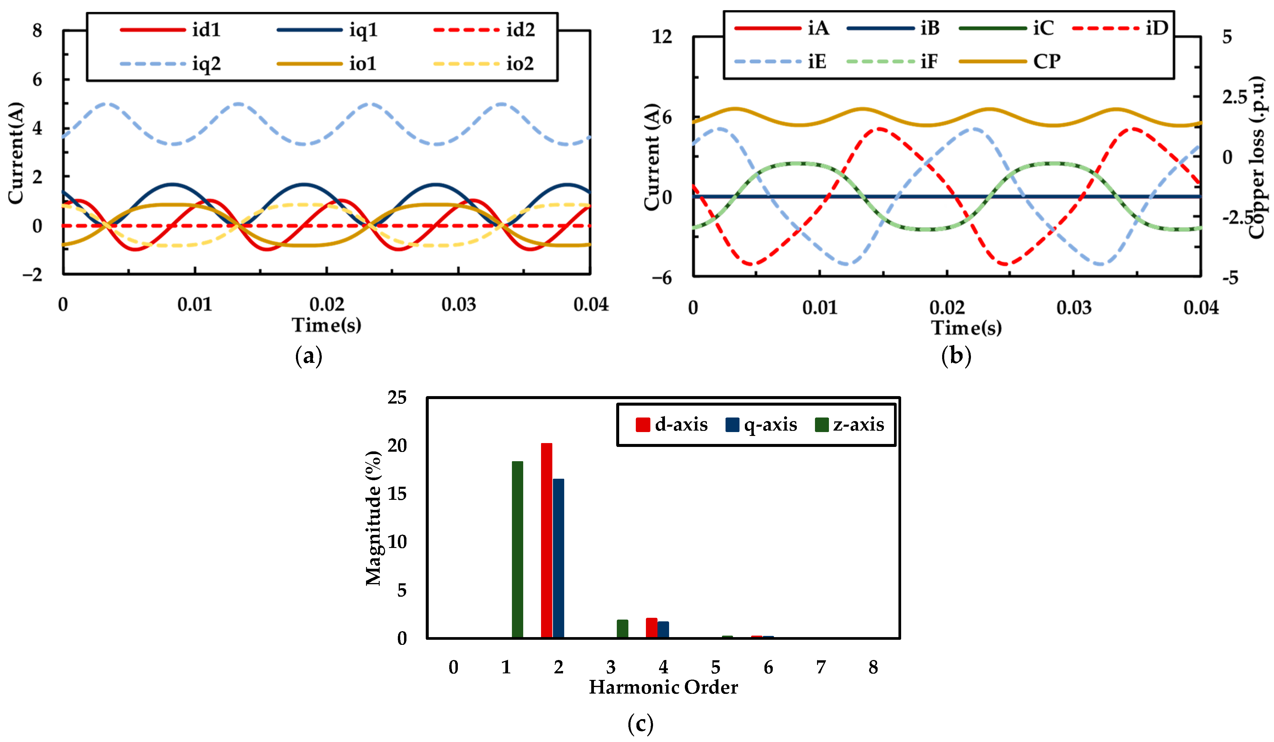
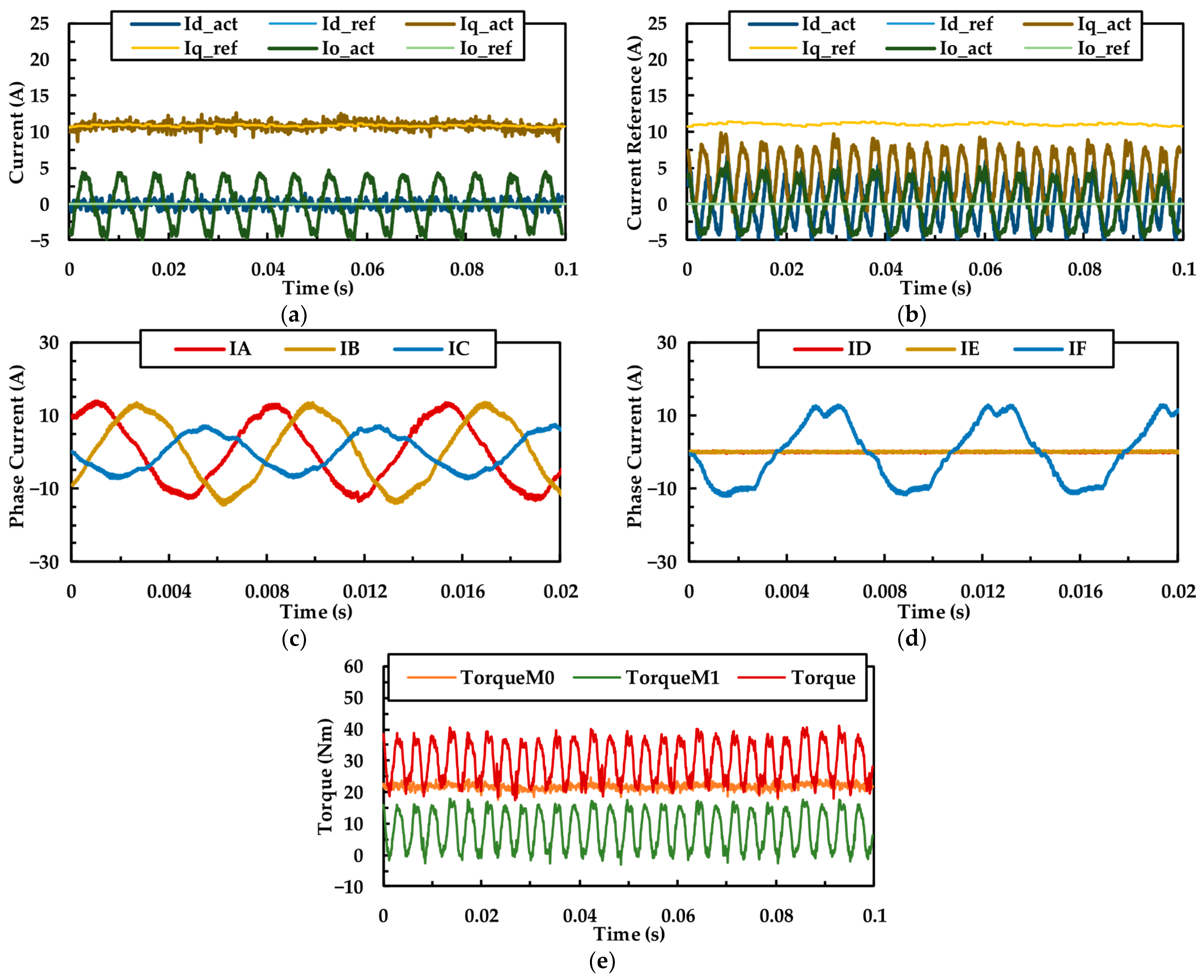
To suppress the torque ripple under the constraint of minimized copper loss, the proposed FTC strategy under SOPF is implemented and the performance is shown in
Figure 10. From
Figure 10a,b,
d-q-z currents are well tracked with the references and are matched with the theoretical waveforms in
Figure 5a. By regulating the current references under
d-q-z axis, the
q axis current ripples of M0 and M1 have the same amplitude but reversed phase angle. For the linearity relation between torque and
q axis current, as
Figure 10e shows, the torque ripples from M0 and M1 are reversed. In the torque sensor, output torque fluctuation is reduced, compared with
Figure 9e. The experimental results in
Figure 10 demonstrate the effectiveness of the proposed fault-tolerant control strategy under SOPF.
Figure 11 shows the performance of NPSDTP-PMSM under DOPF (D, E) without FTC strategy. For the healthy winding set, the M0 closed-up current control is well performed in
d-q axis. However, in M1, the single healthy phase is not sufficient of tracking current references. The harmonic orders in
d-q-z axis are the same with
Figure 9b: 2nd order frequency ripples in
d-q axis and 1st frequency ripple in z-axis. However, compared with
Figure 9b, the average q-axis current in M1 is unable to meet the reference, and zero torque output happens at points where phase current C is zero. In the meantime, through the closed-up speed loop, the
q-axis reference is regulated till the average output torque is sufficient for the load. Thus, the current amplitude in M0 increases compared with
Figure 9c.
As observed in
Figure 9b and
Figure 11b, the currents of the faulted three-phase winding exhibit significant oscillations in the
d-q-z axis when no fault-tolerant control strategy is implemented. These oscillations manifest predominantly as second-order harmonics. This phenomenon occurs because the altered current paths during faults cannot satisfy the original reference currents in the
d-q-z axis. Moreover, according to (8), oscillations in the
q-axis current directly induce electromagnetic torque ripple. Consequently, while the healthy winding set maintains steady torque output (
Figure 9e and
Figure 11e), the faulted set develops second-order torque oscillations. This results in output torque exhibiting second-harmonic ripple. In robotic joint applications, particularly during low-speed operation, this torque oscillation causes significant mechanical vibration and audible noise. These effects compromise joint positioning accuracy and accelerate mechanical wear.
Figure 12 shows performance of the proposed FTC strategy under DOPF (D, E). In
Figure 12a,b, the closed-up current loop is well performed in M0 and M1 and the currents are consistent with the theoretical waveforms in
Figure 6a. The 2nd order ripples in
q axis current in M0 and M1 are phase reversed. In
Figure 12e, the torque ripples in M0 and M1 are counteracted, and the ripples in output torque are reduced, compared with
Figure 11e. The phase currents in
Figure 12c,d are also well matched with the theoretical waveforms in
Figure 6b. Thus, the experimental results in
Figure 12 verify the validation of the proposed fault-tolerant control strategy under DOPF.
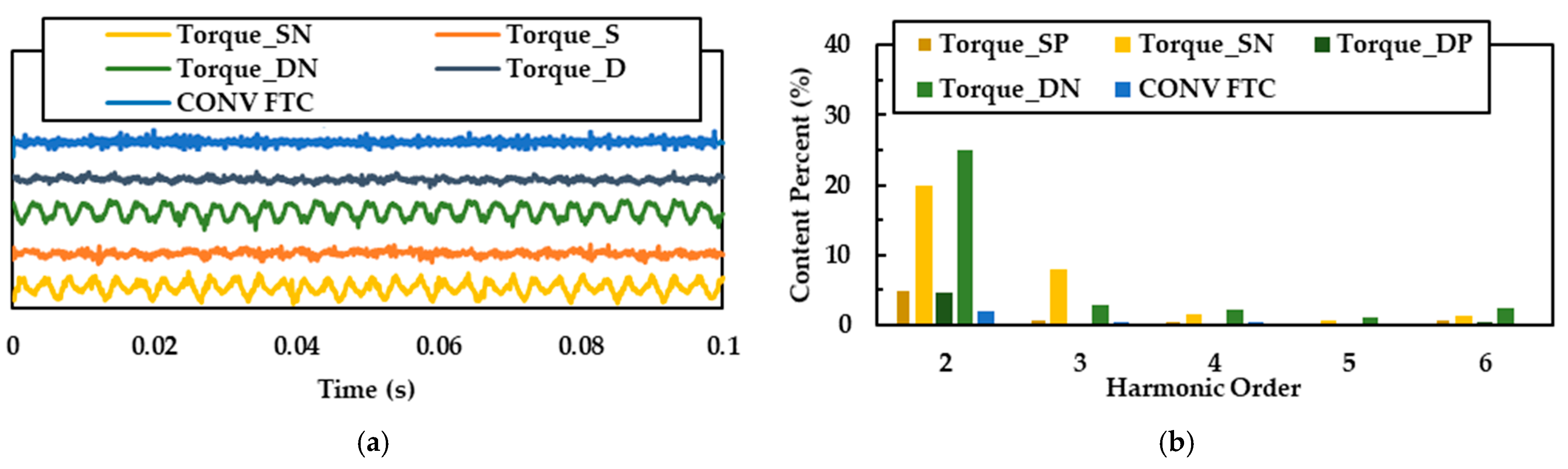
Explicit comparisons of post-fault torque performance are presented in
Figure 13.
Figure 13a superimposes output torque waveforms across conditions, while
Figure 13b provides FFT analysis demonstrating harmonic suppression under both SOPF and DOPF using the proposed strategy.
Table 2 quantifies peak-to-peak torque ripple, revealing reduction rates of 37.2% (SOPF) and 40.4% (DOPF) versus FTC-free operation. These results validate the FTC strategy’s effectiveness in torque ripple mitigation.
Notably, Reference [
9] exhibits higher peak-to-peak ripple dominated by 2 × PWM-frequency harmonics. This stems from single-winding-set operation where elevated phase currents induce magnetic saturation and amplify PWM-induced current ripple.
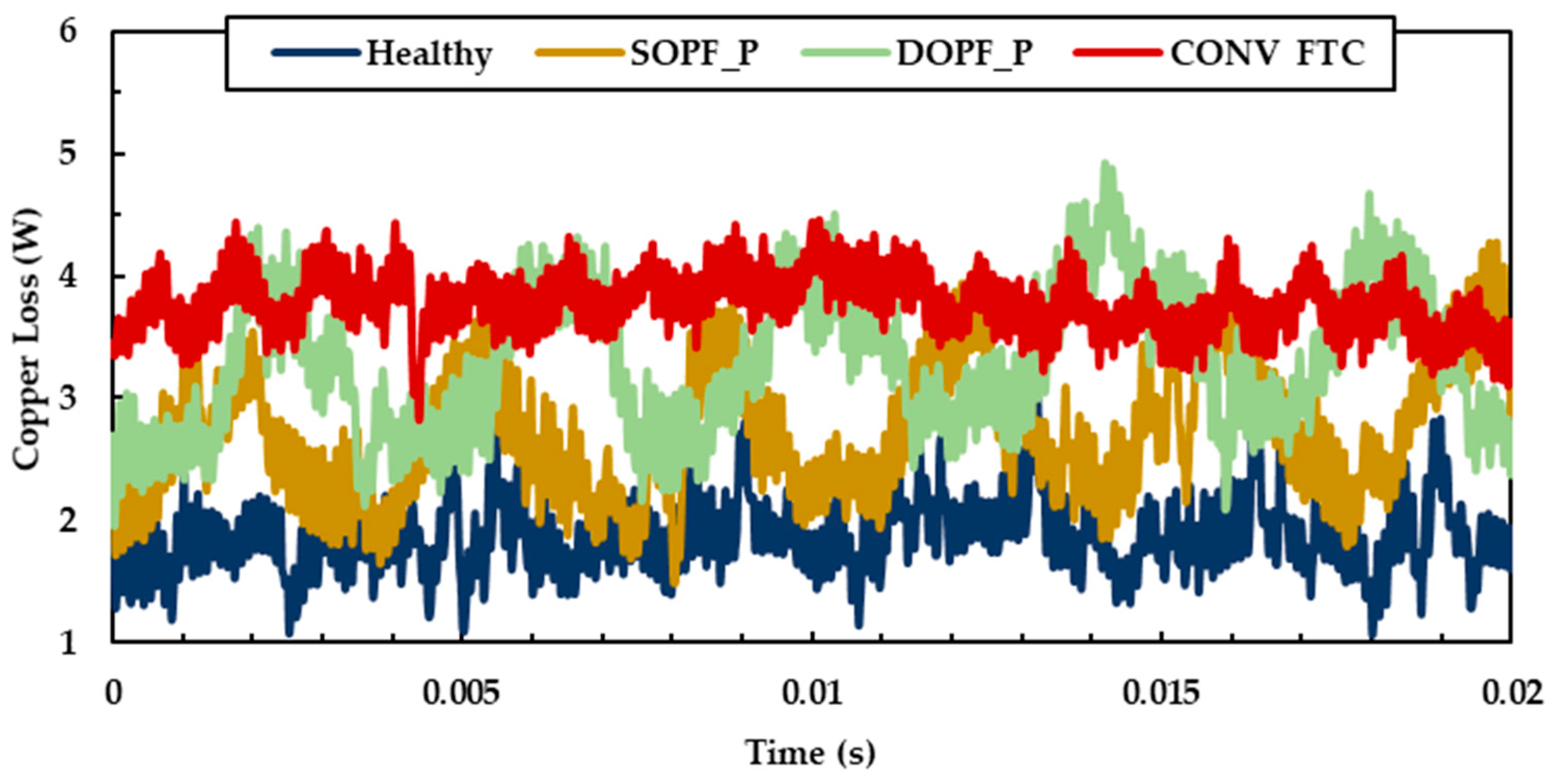
The ICPL waveforms under different working conditions are shown in
Figure 14. And the ACPL of each working condition is illustrated in
Table 3. Under healthy conditions, both sets of windings share the load torque equally. The resulting copper loss is calculated by summing the squares of the six-phase currents and multiplying by the resistance, yielding an average copper loss of 1.7512 W in the healthy state and this value serves as the baseline. Under SOPF, the generated ICPL waveform matches the theoretical waveform shown in
Figure 5b, with an average copper loss of 2.4761 W, which represents an increase of 41% compared to the healthy state. Under DOPF, the copper loss waveform matches the theoretical waveform shown in
Figure 6b, resulting in an average copper loss of 3.0672 W, which is an increase of 75% compared to the healthy state. Furthermore, compared with the FTC method presented in [
9], which produced a copper loss of 3.6254 W (an increase of 107% over the healthy state), the copper loss performance shown in
Figure 14 demonstrates the effectiveness of the proposed fault-tolerant control strategy in suppressing copper loss.
Figure 15 shows the temperature after thermal balance. As observed in
Figure 15, the proposed FTC strategy effectively suppresses both the average temperature rise (overall winding temperature) and hotspot temperature compared to the FTC method in [
9], owing to optimized utilization of the remaining healthy windings. Given the enclosed structure of joint motors, reducing overall copper loss significantly mitigates internal temperature rise within the motor housing. Under these conditions, the enhanced thermal gradient facilitates heat dissipation from hotspot regions. Under SOPF operation, while Phase A current amplitude under proposed strategy remains identical to that in [
9] (twice the healthy-state current), the hotspot temperature is reduced by nearly 40 °C compared to [
9].
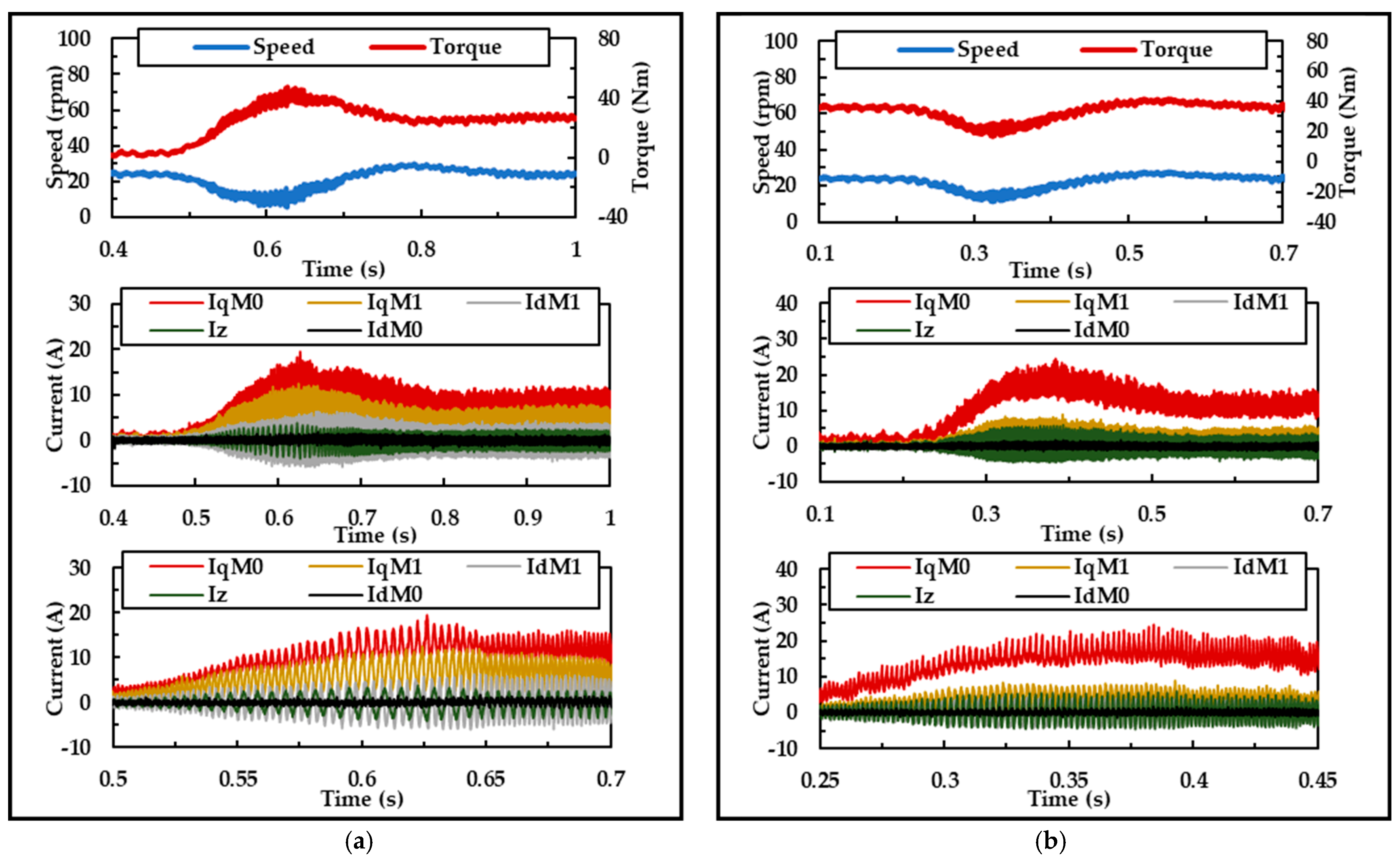
Figure 16 demonstrates the dynamic performance of the proposed fault-tolerant control strategy under step speed variations. In
Figure 16a, operating under a single-phase open-circuit fault, the speed command increases from 24 rpm to 48 rpm at 0.22 s and subsequently decreases back to 24 rpm at 0.46 s. As observed in
Figure 16a, the phase currents remain well-regulated throughout the adjustment period, closely adhering to their reference commands. Similarly,
Figure 16b illustrates the speed regulation performance under a two-phase open-circuit fault, where the currents maintain precise tracking of their references during the speed change.
Figure 17 presents the dynamic performance of the proposed fault-tolerant strategy under high-slop load changes (0–30 Nm within 10 ms, by starting the output of controlled current source connected to the MPB). In
Figure 17a, under SOPF, the load torque changes from 0 Nm to 30 Nm at 0.5 s. Throughout the torque regulation process, the currents consistently follow the references.
Figure 17b shows operation under DOPF, where the load torque changes to 30 Nm at 0.3 s. During this adjustment, the currents continuously track their reference commands.
Collectively,
Figure 16 and
Figure 17 validate the effectiveness of the proposed fault-tolerant strategy in handling both speed variations and load transients.


