Article

Vibration Suppression Algorithm for Electromechanical Equipment in Distributed Energy Supply Systems

1
School of Electrical Engineering, Shenyang Institute of Engineering, Shenyang 110136, China
2
School of Electrical Engineering, Shenyang University of Technology, Shenyang 110136, China
*
Author to whom correspondence should be addressed.
Energies 2025, 18(14), 3757; https://doi.org/10.3390/en18143757
Submission received: 25 June 2025 / Revised: 10 July 2025 / Accepted: 11 July 2025 / Published: 16 July 2025

Abstract

In recent years, distributed energy power supply systems have been widely used in remote areas and extreme environments. However, the intermittent and uncertain output power may cause power grid fluctuations, leading to higher harmonics in electromechanical equipment, especially motors. For permanent magnet synchronous motor (PMSM) systems, an electromagnetic (EM) vibration can cause problems such as energy loss and mechanical wear. Therefore, it is necessary to design control algorithms that can effectively suppress EM vibration. To this end, a vibration suppression algorithm for fractional-slot permanent magnet synchronous motors based on a d-axis current injection is proposed in this paper. Firstly, this paper analyzes the radial electromagnetic force of the fractional-slot PMSM to identify the main source of EM vibration in fractional-slot PMSMs. Based on this, the intrinsic relationship between the EM vibration of fractional-slot PMSMs and the d-axis and q-axis currents is explored, and a method for calculating the d-axis current to suppress the vibration is proposed. Experimental verification shows that the proposed algorithm can effectively suppress EM vibration.

1. Introduction

Distributed energy power supply systems, which convert solar, wind, tidal, and other forms of energy into electricity, have diversified energy utilization. This has improved energy efficiency and the flexibility and reliability of clean energy supply [1]. Consequently, they are extensively used in remote areas and extreme environments where conventional power supply falls short.
However, the intermittent and uncertain output power of distributed energy systems can cause grid fluctuations and affect power quality, consequently disturbing the normal operation of electromechanical equipment [2]. In particular, they may generate vibration in motors. Vibration can lead to significant noise, which has a negative impact on the environment. The impact of vibration and noise depends largely on its frequency and exposure time [3]. Moreover, motor vibration and noise span a wide frequency range and persist over time, making their negative impact particularly significant. The vibration not only directly causes noise, but also leads to structural deformation, which directly affects the service life of electromechanical equipment. In this context, the vibration issue of permanent magnet synchronous motors (PMSMs), which are widely used in various fields, such as industry, electric vehicles, and military applications, has attracted increasing attention.
In the research on motor vibration, some scholars have proposed that the direct cause of vibration lies in the force valleys of radial electromagnetic force caused by the magnetic pole gaps and the slotted structure of PMSMs. To suppress vibration, it is necessary to fill these radial electromagnetic force valleys rather than simply reducing the amplitude of the radial electromagnetic force [4]. Meanwhile, the research has also shown that the radial electromagnetic force of non-zero minimum order has the greatest impact on the vibration of permanent magnet motors [5].
Based on the above theories, ref. [4] proposed the method of adding axially alternating poles between poles, which achieved the suppression of electromagnetic (EM) vibration in surface-mounted permanent magnet motors. To further reduce both pole-frequency and slot-frequency vibrations simultaneously, new pole designs incorporating skewed pole elements based on axially alternating poles were proposed, including the sawtooth skewed pole structure [6,7], double misaligned pole structure [8,9], axially varying pole width structure [10,11], and continuously varying pole width structure [12]. All these designs have achieved good results in suppressing motor vibration [6,7,8,9,10,11,12].
In addition to suppressing vibration through the design of special pole structures, some scholars have also focused on the design and optimization of stator teeth and yokes to achieve the goal of vibration suppression. For example, the addition of magnetic barriers in the stator yoke in [13] and the insertion of wedge-shaped poles at the slot openings in [10] have all achieved good results in suppressing EM vibration.
References [14,15] comprehensively considered the impact of EM vibration and torque ripple, compared the effects of traditional skewed poles, skewed slots, and segmented rotors on vibration and torque ripple, and proposed an asymmetric pole design method to achieve better comprehensive performances in vibration and torque.
However, the methods of suppressing motor vibration through motor structural optimization mentioned above will lead to increased manufacturing difficulty and cost of the motor. Therefore, developing control strategies that can suppress motor vibration has become a research hotspot in recent years.
Since current harmonics often have a negative impact on motor vibration, some scholars have suppressed vibration by reducing current harmonics. At present, the suppression of current harmonics is mainly achieved through optimized control strategies [16,17] and the construction of resonant controllers [18,19,20]. Reference [21] designed a multi-rotating PI control algorithm using different speed spatial coordinate systems and then generated compensation voltage through PI regulators.
However, the aforementioned papers did not delve into the intrinsic relationship between current harmonics and motor vibration. They merely assumed that reducing current harmonics would lead to reduced motor vibration, which is clearly not rigorous. Therefore, the relevant literature discussed the characteristics of low-order electromagnetic forces generated by the interaction between the armature field of fractional-slot motors and the permanent magnet field, and used a harmonic injection to weaken the low-order electromagnetic forces to achieve vibration reduction. Based on this, ref. [22] implemented the online calculation of compensation current amplitude and phase using a neural network algorithm, further enhancing the practicality of the method. Reference [23] suppressed slot-frequency vibration through the method of flux-linkage harmonic injection.
Both of these methods can effectively suppress motor vibration, but they involve a large amount of computation. Moreover, any deviation in the calculation of the required current harmonic phase may lead to increased motor vibration. To overcome these issues, this paper proposes a vibration suppression algorithm for fractional-slot PMSMs based on a d-axis current injection. This algorithm is simple to compute and highly effective.

2. The Main Sources of Fractional-Slot PMSM Vibration

EM vibration is primarily caused by radial electromagnetic force (REMF) generated in the air-gap magnetic field. In this process, the REMF acts on the stator teeth, then transfers to the yoke, causing motor vibration. As the main source of EM vibration, this paper first analyzes the characteristics of the REMF, laying the foundation for vibration suppression algorithm development.
According to the Maxwell stress tensor method, the REMF generated in the air-gap magnetic field can be expressed as
p r θ m , t = B r θ m , t 2 B t θ m , t 2 2 μ 0 p t θ m , t = B r θ m , t B t θ m , t μ 0
where pr(θm, t) represents the radial electromagnetic force density; pt(θm, t) represents the tangential electromagnetic force density; Br(θm, t) represents the radial air-gap magnetic flux density; Bt(θm, t) represents the tangential air-gap magnetic flux density; μ0 represents air permeability; θm represents the mechanical angle; and t represents time.
It is generally recognized that the primary source of electromagnetic vibration is the REMF. Therefore, this chapter focuses on analyzing REMF density. Since the amplitude of the tangential air-gap magnetic flux density is much lower compared to the radial component, it can usually be neglected in the analysis. Thus, the expression for the radial electromagnetic force density can be simplified as
p r θ m , t = B r θ m , t 2 2 μ 0
The radial air-gap magnetic (2) flux density Br(θm, t) consists of three components: the permanent magnet magnetomotive force FPM(θm, t) under a slotless model, the armature magnetomotive force FAM(θm, t) under a slotless model, and the air-gap permeance Ʌ(θm, t) under a slotted model. Its expression is
p r θ m , t = F PM θ m , t + F AM θ m , t 2 Λ θ m 2 2 μ 0
As shown in (3), the REMF is influenced by three components: the permanent magnet magnetomotive force under a slotless model, the armature magnetomotive force under a slotless model, and the air-gap permeance under a slotted model. These three components can be expressed as Fourier series in the following forms:
{ F PM ( θ m , t ) = u = 1,3 , 5 , . . . F u c o s ( u p n θ m + u p n ω m t ) F AM n ( θ m , t ) = v = 6 k + 1 k = 0,1 , 2 , . . . F v c o s ( | v | p n p 0 θ m + | v | v n p n ω m t ) Λ ( θ m ) = μ 0 δ ( θ m ) + H m = h = 0,1 , 2,3 . . . Λ h c o s ( h Z θ m )
where Fu represents the amplitude of the u-th harmonic of the permanent magnet magnetomotive force. pn represents the number of pole pairs. ωm represents the mechanical angular velocity. Fv represents the amplitude of the v-th harmonic of the armature magnetomotive force. Ʌh represents the amplitude of the h-th harmonic of the air-gap permeance. Z represents the number of motor slots.
Substituting (4) into (2) yields:
p r θ m , t = Λ θ m 2 2 μ 0 F PM θ m , t 2 + 2 F PM θ m , t F AM θ m , t + F AM θ m , t 2
As shown in (5), the REMF of a PMSM can be divided into three components: the self-interaction of the permanent magnet field, the interaction between the permanent magnet field and the armature field, and the self-interaction of the armature field. The expanded expressions for these three components are given in (6) to (8).
p r P ( θ m , t ) = F PM ( θ m , t ) 2 Λ ( θ m ) 2 2 μ 0 = 1 2 μ 0 ( u 1 = 1,3 , 5 , . . . u 2 = 1,3 , 5 , . . . h 1 = 0,1 , 2 , . . . h 2 = 0,1 , 2 , . . . F u 1 F u 2 Λ h 1 Λ h 2 8 ( c o s ( ( ( u 1 + u 2 ) p n ± ( h 1 ± h 2 ) Z ) θ m + ( u 1 + u 2 ) p n ω m t ) ) + u 1 = 1,3 , 5 , . . . u 2 = 1,3 , 5 , . . . h 1 = 0,1 , 2 , . . . h 2 = 0,1 , 2 , . . . F u 1 F u 2 Λ h 1 Λ h 2 8 ( c o s ( ( ( u 1 u 2 ) p n ± ( h 1 ± h 2 ) Z ) θ m + ( u 1 u 2 ) p n ω m t ) ) )
p r PA ( θ m , t ) = F PM ( θ m , t ) F AM ( θ m , t ) Λ ( θ m ) 2 2 μ 0 = 1 μ 0 ( u = 1,3 , 5 , . . . v = 6 k + 1 k = 0,1 , 2 , . . . h 1 = 0,1 , 2 , . . . h 2 = 0,1 , 2 , . . . F u F v Λ h 1 Λ h 2 8 ( c o s ( ( ( u + | v | p 0 ) p n ± ( h 1 ± h 2 ) Z ) θ m + ( u + | v | v ) p n ω m t ) ) + u 1 = 1,3 , 5 , . . . v = 6 k + 1 k = 0,1 , 2 , . . . h 1 = 0,1 , 2 , . . . h 2 = 0,1 , 2 , . . . F u F v Λ h 1 Λ h 2 8 ( c o s ( ( ( u | v | p 0 ) p n ± ( h 1 ± h 2 ) Z ) θ m + ( u | v | v ) p n ω m t ) ) )
p r A ( θ m , t ) = F AM ( θ m , t ) 2 Λ ( θ m ) 2 2 μ 0 = 1 2 μ 0 ( v 1 = 6 k + 1 v 2 = 6 k + 1 k = 0,1 , 2 , . . . h 1 = 0,1 , 2 , . . . h 2 = 0,1 , 2 , . . . F v 1 F v 2 Λ h 1 Λ h 2 8 ( c o s ( ( ( v 1 + v 2 ) p n p 0 ± ( h 1 ± h 2 ) Z ) θ m + ( | v 1 | v 1 + | v 2 | v 2 ) p n ω m t ) ) + v 1 = 6 k + 1 v 2 = 6 k + 1 k = 0,1 , 2 , . . . h 1 = 0,1 , 2 , . . . h 2 = 0,1 , 2 , . . . F v 1 F v 2 Λ h 1 Λ h 2 8 ( c o s ( ( ( v 1 v 2 ) p n p 0 ± ( h 1 ± h 2 ) Z ) θ m + ( | v 1 | v 1 | v 2 | v 2 ) p n ω m t ) ) )
Since the armature magnetic field is usually much smaller than the permanent magnet field, the REMF generated by the armature field’s self-interaction, as shown in (8), is typically neglected.
For fractional-slot PMSMs, the permanent magnet magnetic field contains all odd harmonic components, while the armature magnetic field contains all odd harmonics except multiples of 3. Taking a 10-pole 12-slot PMSM as an example, the main harmonic orders of its radial electromagnetic force density are shown in Table 1 and Table 2.
Table 1 and Table 2 list the main possible REMF harmonics of the 10−pole 12−slot PMSM based on (6) and (7). To verify their accuracy, a finite element simulation was conducted on a 10-pole 12-slot PMSM. The harmonic amplitudes of REMF density are presented in Figure 1.
Since REMFs with a frequency of 0 do not cause vibration, they are ignored. For clarity, REMF harmonics are hereafter denoted in the form “pr(temporal frequency, spatial order)”.
As shown in Figure 1, the REMF density of the 10-pole 12-slot PMSM has higher amplitudes at pr(4pn, 8), pr(2pn, 10), and pr(−2pn, 2). This conclusion matches Table 1 and Table 2, confirming the correctness of the theoretical derivation and indicating that these REMF harmonics dominate in the 10-pole 12-slot PMSM.
According to [24], the contribution of different spatial-order radial electromagnetic forces to EM vibration can be expressed as:
Y m 2 = 12 R y 3 R p rm 2 E T y 2 m 2 1 2
where Ym≥2 represents the vibration caused by REMFs of orders two and above. Ry represents the average yoke radius. R represents the stator inner diameter. m represents the order of the REMF. prm≥2 represents the amplitude of the m-th-order REMF. E represents Young’s modulus. Ty represents the yoke radial thickness.
As shown in (9), the vibration caused by the REMF is proportional to the amplitude and inversely proportional to the fourth power of the order. Thus, the REMF that contributes most to the EM vibration is the lowest non-zero-order REMF.
Based on the previous conclusions, for a 10-pole 12-slot PMSM, the REMF that has the greatest impact on vibration is pr(−2pn, 2). Therefore, in the design of the vibration suppression algorithm, focus should be on suppressing this REMF harmonic.

3. Vibration Suppression Algorithm for Fractional-Slot PMSMs Based on a d-Axis Current Injection

Taking the 10-pole 12-slot PMSM as an example, this paper analyzes the REMF from the view of FOC. When the motor operates in an unsaturated state, the air-gap magnetic field is typically regarded as the superposition of the armature magnetic field and the permanent magnet magnetic field. In this case, in the FOC, the armature magnetic field can be approximated as the superposition of the d-axis and q-axis magnetic fields, which can be expressed as
B r θ m , t = B PM θ m , t + B AM θ m , t = B PM θ m , t + B a d θ m , t + B a q θ m , t
where Bad(θm, t) and Baq(θm, t) represent the magnetic flux densities generated by the d-axis current and q-axis current in the air gap.
When only the fundamental current is considered, the Fourier expansion of each term in (10) is
{ B PM ( θ m , t ) = u = 1,3 , 5 . . . B PM u c o s ( u p n θ m + u p n ω m t ) B ad ( θ m , t ) = v = 1,5 , 7 . . . B ad ν c o s ( v θ m + | v | v p n ω m t ) B aq ( θ m , t ) = v = 1,5 , 7 . . . B aq v c o s ( ν θ m + | v | v p n ω m t π 2 )
As previously mentioned, in the 10-pole 12-slot motor, the 5th- and 7th-order components of the armature magnetic field are both significant. Their interaction generates pr(−2pn, 2) that has the greatest impact on motor vibration. Therefore, both the 5th- and 7th-order components must be considered. At this point, the air-gap magnetic field of the motor can be represented by Figure 2.
As shown in Figure 2, the main harmonics of the air-gap magnetic field in a fractional-slot machine can be expressed as
B r θ m , t = B PM 1 cos 5 θ m + ω e t + B ad 5 cos 5 θ m + ω e t + B aq 5 cos 5 θ m + ω e t π 2 + B ad 7 cos 7 θ m ω e t + B aq 7 cos 7 θ m ω e t π 2
where BPM1 represents the amplitude of the permanent magnet fundamental magnetic field. Bad5 and Baq5 represent the amplitudes of the 5th armature magnetic field generated by the d-axis current and q-axis current, respectively. Bad7 and Baq7 represent the amplitudes of the 7th armature magnetic field generated by the d-axis current and q-axis current, respectively.
Based on the previous conclusions, in the 10-pole 12-slot motor, pr(−2pn, 2) is dominant. Thus, the REMF analysis is simplified as follows:
(1)
Only consider pr(−2pn, 2);
(2)
The motor is an ideal surface-mounted motor, satisfying Ld = Lq, and adopts id = 0 control.
Under these conditions, there is no d-axis current component in the motor, and the REMF satisfies:
p r 2 p n , 2 = B PM 1 B aq 7 2 cos 2 θ m 2 ω e π 2 + B a q 5 B aq 7 2 cos 2 θ m 2 ω e
To suppress this radial electromagnetic force, a certain d-axis current is injected into the PMSM. At this time, the electromagnetic force can be expressed as
p r 2 p n , 2 = B PM 1 B aq 7 2 cos 2 θ m 2 ω e t π 2 + B aq 5 B aq 7 2 cos 2 θ m 2 ω e t + B PM 1 B ad 7 2 cos 2 θ m 2 ω e t + B aq 5 B ad 7 2 cos 2 θ m 2 ω e t + π 2 + B ad 5 B ad 7 2 cos 2 θ m 2 ω e t + B ad 5 B aq 7 2 cos 2 θ m 2 ω e t π 2 = 1 2 B PM 1 B aq 7 + B ad 5 B aq 7 B aq 5 B ad 7 cos 2 θ m 2 ω e t π 2 + 1 2 B PM 1 B ad 7 + B aq 5 B aq 7 + B ad 5 B ad 7 cos 2 θ m 2 ω e t
Since the amplitude of the REMF generated by the armature magnetic field itself is usually small, it is neglected here. Equation (13) can be rewritten as
p r 2 p n , 2 = 1 2 B PM 1 B aq 7 cos 2 θ m 2 ω e t π 2 + 1 2 B PM 1 B ad 7 cos 2 θ m 2 ω e t = 1 2 B PM 1 B aq 7 sin 2 θ m 2 ω e t + B ad 7 cos 2 θ m 2 ω e t
According to (15), to nullify pr(−2pn, 2), the following condition must be met:
B ad 7 = B aq 7 tan 2 θ m 2 ω e t
Assuming the amplitude of the armature magnetic field is proportional to the current amplitude, (16) can be equivalently expressed as
i d = i q tan 2 θ m 2 θ e
Theoretically, when the d-axis current satisfies (17), pr(−2pn, 2) becomes zero. However, since (17) involves a tangent function with an infinite range, current limiting is required to ensure:
i d = i q tan 2 p n 2 p n θ e , i d i s max 2 i q 2
Based on (18), the d-axis current required for the vibration suppression algorithm can be calculated.

4. Experiment Verification

To verify the effectiveness of the proposed vibration suppression algorithm, a 10-pole 12-slot PMSM was used for the experimental validation. Meanwhile, an accelerometer was used to measure the vibration. The accelerometer selected in this paper was magnetically attached to the motor and had a measurement accuracy of 0.78 mg. The motor parameters are listed in Table 3, and the test platform is shown in Figure 3.

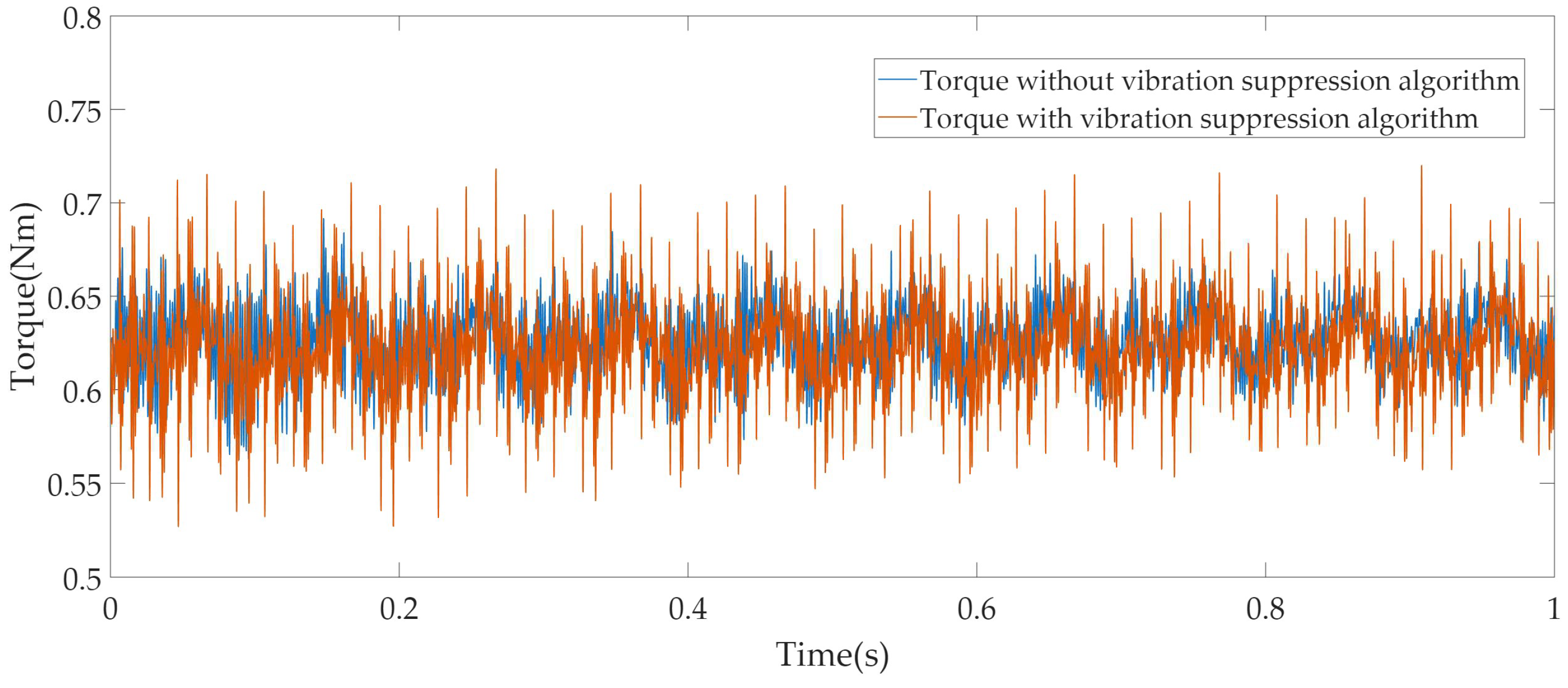
4.1. Experimental Results at 600 r/min

The experiment was first conducted at 600 r/min with a rated load, at which the fundamental frequency was 50 Hz. The experiment results of the proposed vibration suppression algorithm are shown in Figure 4, Figure 5, Figure 6 and Figure 7.
As shown in Figure 4, the comparison of the amplitude values of the harmonics of the vibration acceleration is presented. In conjunction with Table 4, it can be seen that without the vibration suppression algorithm, the vibration acceleration is concentrated at even multiples of the fundamental frequency, with the vibration acceleration at the second harmonic being the largest, having an amplitude of 0.45 m/s2.
In Table 4, a hyphen “-” denotes an amplitude so small that it can be neglected. The same convention applies to all subsequent tables. When the motor operates with the proposed vibration suppression algorithm, in addition to the even harmonics, a large number of odd harmonics also appear. However, the peak value is significantly reduced. Among them, the largest second-harmonic vibration acceleration is 0.19 m/s2, which is reduced by 57.78% compared with the case without the vibration suppression algorithm.
As shown in Figure 5, the d-axis and q-axis currents are presented. Figure 5a shows the d-axis and q-axis currents without the vibration suppression algorithm, when the motor operating under the control of id = 0. As can be seen from Figure 5a, the d-axis current fluctuates within the range of −0.62 A to 0.57 A, while the q-axis current fluctuates within the range of 4.41 A to 5.43 A.
Figure 5b shows the d-axis and q-axis currents with the vibration suppression algorithm. As can be seen from Figure 5b, the d-axis current fluctuates within the range of −1.21 A to 1.35 A, while the q -axis current fluctuates within the range of 4.24 A to 5.60 A.
Obviously, under the influence of the proposed vibration suppression algorithm, the fluctuation of the d-axis current is significantly increased, which is in line with the expectation of (18). Meanwhile, since the SPMSM still has a certain degree of saliency, the increase in the fluctuation of the d-axis current will also affect the fluctuation of the q-axis current. By performing a Fourier decomposition on the A-phase current, the harmonic components of the phase current can be obtained, as shown in Figure 6.
As can be seen from Figure 6, without the vibration suppression algorithm, the current contains harmonics such as the 5th, 7th, and 11th. With the vibration suppression algorithm, all current harmonics increase, with specific amplitude values shown in Table 4.
As shown in Figure 7, the torque fluctuates between 0.56 Nm and 0.69 Nm without the vibration suppression algorithm, resulting in a torque ripple rate of 10.4%. When the vibration suppression algorithm is applied, the torque fluctuates between 0.53 Nm and 0.72 Nm, increasing the torque ripple rate to 15.2%. This indicates that although the vibration suppression algorithm introduces additional current harmonics into the motor, causing an increase in torque ripple, the motor can still maintain a stable operation.
From the experimental results, it can be seen that the additional current harmonics introduced by the proposed vibration suppression algorithm effectively suppress the even-order vibrations, but also cause odd-order vibrations. Meanwhile, the peak vibration of the PMSM is significantly reduced, which is of great significance for the safe and stable operation of electromechanical equipment.

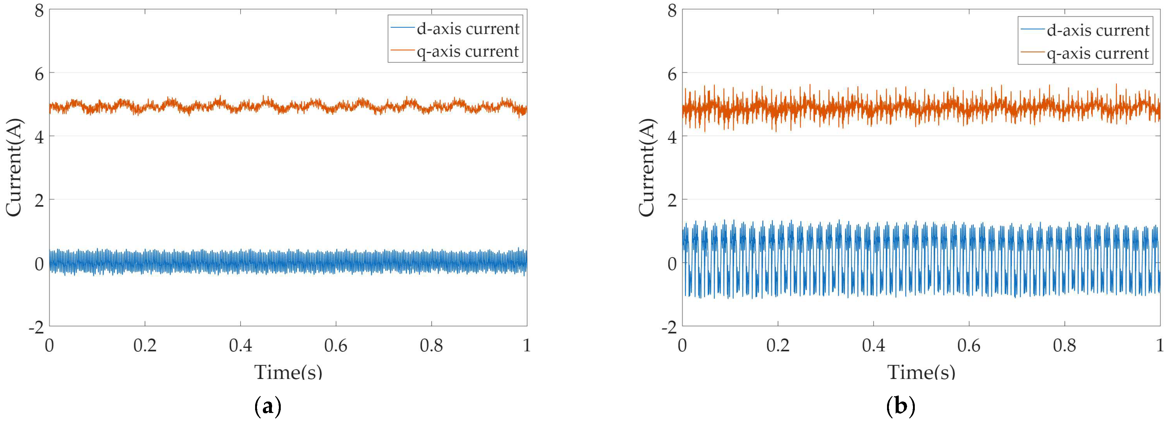
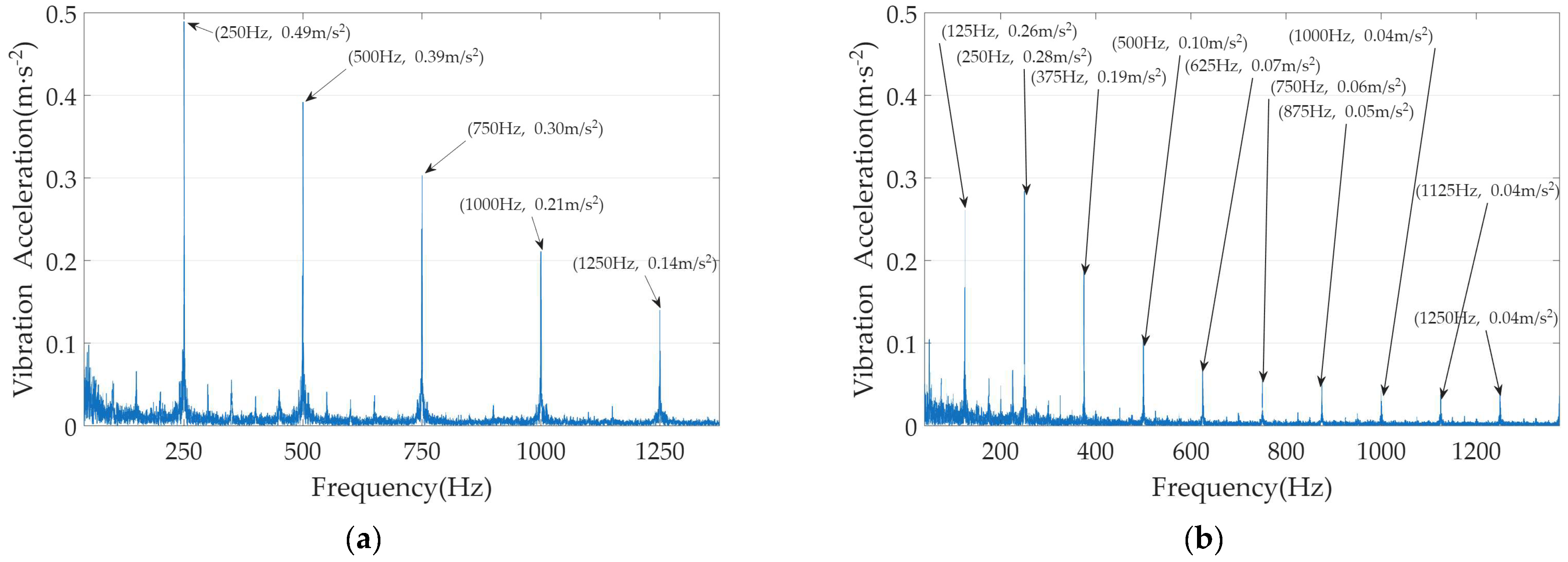
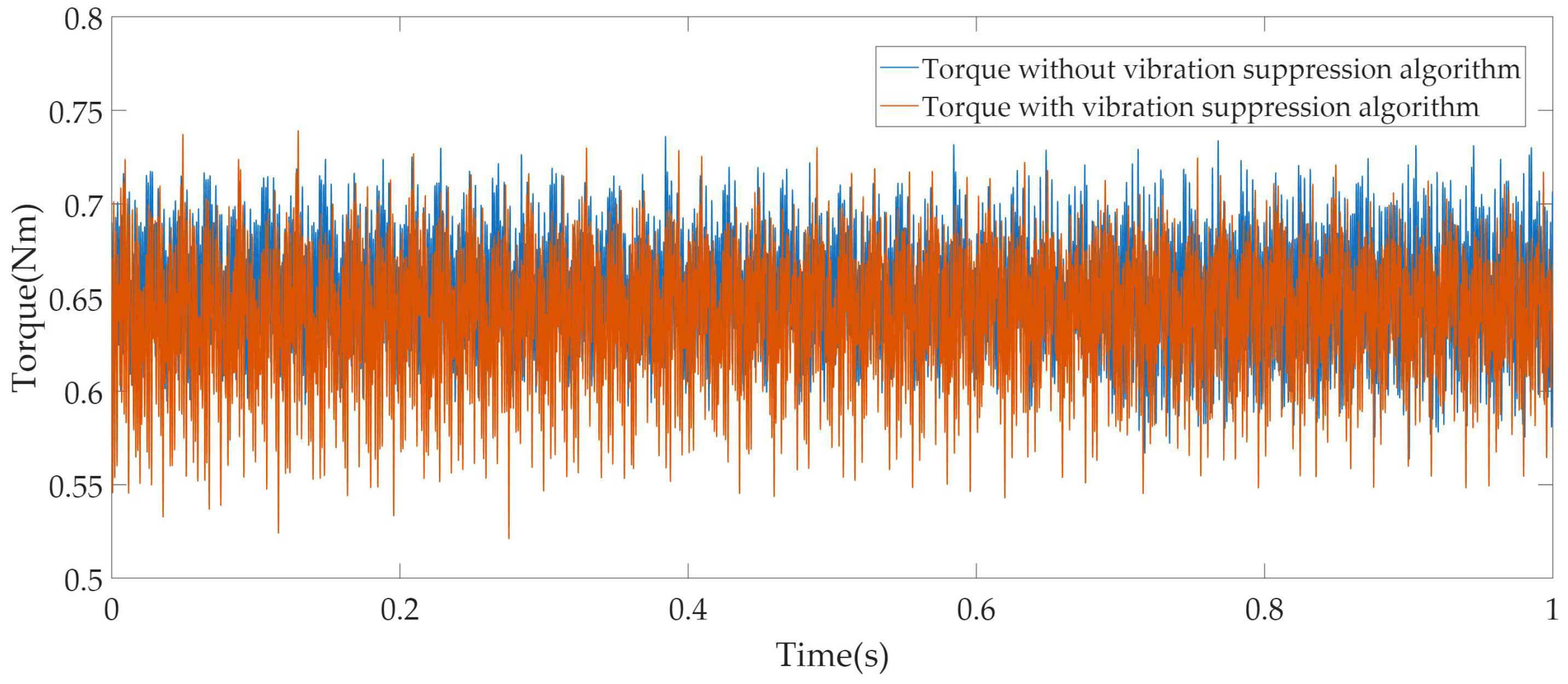
4.2. Experimental Results at 1500 r/min

The experiment was first conducted at a rated speed with a rated load, at which the fundamental frequency was 125 Hz. The experiment results of the proposed vibration suppression algorithm are shown in Figure 8, Figure 9, Figure 10 and Figure 11.
As shown in Figure 8, the comparison of the amplitude values of the harmonics of the vibration acceleration is presented. In conjunction with Table 5, it can be seen that without the vibration suppression algorithm, the vibration acceleration is concentrated at even multiples of the fundamental frequency, with the vibration acceleration at the second harmonic being the largest, having an amplitude of 0.49 m/s2.
When the motor operates with the proposed vibration suppression algorithm, in addition to the even harmonics, a large number of odd harmonics also appear. However, the peak value is significantly reduced. Among them, the largest second-harmonic vibration acceleration is 0.28 m/s2, which is reduced by 42.86% compared with the case without the vibration suppression algorithm.
As shown in Figure 9, the d-axis and q-axis currents are presented. As can be seen from Figure 9a, the d-axis current fluctuates within the range of −0.66 A to 0.58 A, while the q-axis current fluctuates within the range of 4.80 A to 6.38 A. Compared to 600 r/min, the amplitude of the q-axis current has increased. This is because the prototype used in the experiment has a relatively low power rating, and the damping effect resulting from the increase in speed has a significant impact on the motor operation.
Figure 9b shows the d-axis and q-axis currents with the vibration suppression algorithm. As can be seen from Figure 9b, the d-axis current fluctuates within the range of −0.71 A to 0.85 A, while the q-axis current fluctuates within the range of 4.44 A to 6.30 A. At this point, the motor is operating at rated torque and rated speed conditions, and the q-axis current is already close to the rated current. According to (18), the range of variation for the d-axis current is very small in these conditions. Therefore, the fluctuation of the d-axis current does not increase significantly as 600 r/min. As a result, the effectiveness of vibration suppression is also reduced.
By performing a Fourier decomposition on the A-phase current, the harmonic components of the phase current can be obtained, as shown in Figure 10 and Table 5. As can be seen from Table 5, although a large number of even-order harmonics still appear in the current, the amplitudes of the 5th- and 7th-order harmonics have not increased significantly. This is also due to the motor operating under rated conditions.
As shown in Figure 11, the torque fluctuates between 0.56 Nm and 0.74 Nm without the vibration suppression algorithm, resulting in a torque ripple rate of 13.8%. When the vibration suppression algorithm is applied, the torque fluctuates between 0.52 Nm and 0.74 Nm, increasing the torque ripple rate to 17.4%.
From the experimental results, it can be seen that although the d-axis current can only vary within a very small range when the motor is operating under rated conditions, the proposed vibration suppression algorithm still ensures a certain degree of suppression of even-order vibrations.

5. Conclusions

This paper proposes a vibration suppression algorithm based on a d-axis current injection and provides a detailed design process. Experimental verification shows that the proposed vibration suppression algorithm can significantly reduce the peak vibration acceleration at different speeds. For example, reductions of 57.78% and 42.86% were achieved at speeds of 600 r/min and 1500 r/min, respectively. At the same time, the algorithm can be implemented with simple calculations.
Although the proposed vibration suppression algorithm slightly increases torque ripple due to the additional current injected into the motor, its significant vibration suppression effect still offers strong practical value, providing an effective solution for the vibration suppression of electromechanical equipment in distributed energy systems.

Author Contributions

Conceptualization, H.W.; methodology, H.W. and F.H.; software, G.Z.; validation, B.Z. and G.Z.; formal analysis, B.Z.; investigation, B.Z.; resources, F.H.; data curation, F.H.; writing—original draft preparation, G.Z.; writing—review and editing, B.Z. and H.W.; visualization, F.H.; supervision, F.H.; project administration, H.W.; funding acquisition, H.W. All authors have read and agreed to the published version of the manuscript.

Funding

This research was funded by Department of Science and Technology of Liaoning Province grant number 2024-MSLH-328/2024-MSLH-326 and the APC was funded by 2024-MSLH-328/2024-MSLH-326.

Data Availability Statement

The data presented in this study are available on request from the corresponding author. The data are not publicly available due to institutional restrictions.

Conflicts of Interest

The authors declare no conflict of interest.

References

  1. Zhang, H.; Zhang, O.; Li, P.; Yue, X.; Tan, Z. Two-Stage Robust Optimization Model for Flexible Response of Micro-Energy Grid Clusters to Host Utility Grid. Energies 2025, 18, 3030. [Google Scholar] [CrossRef]
  2. He, L.; Zhu, Y.; Liu, G.; Cao, C. Simulation Analysis and Experiment Research of Transformer Vibration Based on Electric–Magnetic–Mechanic Coupling. Energies 2025, 18, 2238. [Google Scholar] [CrossRef]
  3. Stosiak, M.; Yatskiv, I.; Prentkovskis, O.; Karpenko, M. Reduction of Pressure Pulsations over a Wide Frequency Range in Hydrostatic Systems. Machines 2025, 13, 25. [Google Scholar] [CrossRef]
  4. Wang, S.; Hong, J.; Sun, Y.; Zheng, Z.; Cao, H. Filling Force Valley with Interpoles for Pole-Frequency Vibration Reduction in Surface-Mounted PM Synchronous Machines. IEEE Trans. Ind. Electron. 2019, 67, 6709–6720. [Google Scholar]
  5. Zhu, Z.; Xia, Z.; Wu, L.; Jewell, G.W. Analytical Modeling and Finite-Element Computation of Radial Vibration Force in Fractional-Slot Permanent-Magnet Brushless Machines. IEEE Trans. Ind. Appl. 2010, 46, 1908–1918. [Google Scholar] [CrossRef]
  6. Wang, S.; Yang, Z.; Liu, C. Vibration Reduction Characteristics of Permanent Magnet DC Motors With Sawtooth Edge Poles. IEEE Trans. Energy Convers. 2021, 36, 737–745. [Google Scholar] [CrossRef]
  7. Wang, S.; Hong, J.; Sun, Y.; Cao, H. Effect Comparison of Zigzag Skew PM Pole and Straight Skew Slot for Vibration Mitigation of PM Brush DC Motors. IEEE Trans. Ind. Electron. 2019, 67, 4752–4761. [Google Scholar]
  8. Yang, Z.; Wang, S.; Hong, J.; Liu, C. Vibration Reduction by Segmented Continuous Variable Width Pole for Rotating Armature Permanent Magnet Motors. IEEE Trans. Ind. Appl. 2021, 57, 2381–4802. [Google Scholar] [CrossRef]
  9. Hong, J.; Wang, S.; Sun, Y.; Sun, X.; Cao, H. Piecewise Stagger Poles with Continuous Skew Edge for Vibration Reduction in Surface-Mounted PM Synchronous Machines. IEEE Trans. Ind. Electron. 2020, 68, 8498–8506. [Google Scholar]
  10. Yang, Z.; Wang, S.; Sun, Y.; Cao, H. Vibration Reduction by Magnetic Slot Wedge for Rotating Armature Permanent Magnet Motors. IEEE Trans. Ind. Appl. 2020, 56, 4882–4888. [Google Scholar] [CrossRef]
  11. Wang, S.; Hong, J.; Sun, Y.; Cao, H. Analysis and Reduction of Electromagnetic Vibration of PM Brush DC Motors. IEEE Trans. Ind. Appl. 2019, 55, 4605–4612. [Google Scholar] [CrossRef]
  12. Hong, J.; Wang, S.; Sun, Y.; Cao, H. An Effective Method with Copper Ring for Vibration Reduction in Permanent Magnet Brush DC Motors. IEEE Trans. Magn. 2018, 54, 1–5. [Google Scholar] [CrossRef]
  13. Dajaku, G.; Xie, W.; Gerling, D. Reduction of Low Space Harmonics for the Fractional Slot Concentrated Windings Using a Novel Stator Design. IEEE Trans. Magn. 2014, 50, 1–12. [Google Scholar] [CrossRef]
  14. Wang, D.; Peng, C.; Li, J.; Wang, C. Comparison and Experimental Verification of Different Approaches to Suppress Torque Ripple and Vibrations of Interior Permanent Magnet Synchronous Motor for EV. IEEE Trans. Ind. Electron. 2022, 70, 2209–2220. [Google Scholar] [CrossRef]
  15. Chen, P.; Wang, D.; Wang, B.; Li, J.; Xu, C.; Wang, X. Torque Ripple and Electromagnetic Vibration Suppression in Permanent Magnet Synchronous Motor Using Segmented Rotor with Different Pole Widths. IEEE Trans. Magn. 2022, 58, 1–5. [Google Scholar]
  16. Chen, L.; Chen, M.; Li, B.; Sun, X.; Jiang, F. Harmonic Current Suppression of Dual Three-Phase Permanent Magnet Synchronous Motor with Improved Proportional-Integral Resonant Controller. Energies 2025, 18, 1340. [Google Scholar] [CrossRef]
  17. Xu, J.; Wei, Z.; Wang, S. Active Disturbance Rejection Repetitive Control for Current Harmonic Suppression of PMSM. IEEE Trans. Power Electron. 2023, 38, 14423–14437. [Google Scholar] [CrossRef]
  18. Yepes, A.G.; Freijedo, F.D.; Lopez, Ó.; Doval-Gandoy, J. High-performance digital resonant controllers implemented with two integrators. IEEE Trans. Power Electron. 2011, 26, 563–576. [Google Scholar] [CrossRef]
  19. Yepes, A.G.; Freijedo, F.D.; Lopez, Ó.; Doval-Gandoy, J. Analysis and design of resonant current controllers for voltage-source converters by means of Nyquist diagrams and sensitivity function. IEEE Trans. Ind. Electron. 2011, 58, 5231–5250. [Google Scholar] [CrossRef]
  20. Zhou, S.; Zhang, Y.; Liu, Z.; Liu, J.; Zhou, L. Implementation of Cross-Coupling Terms in Proportional-Resonant Current Control Schemes for Improving Current Tracking Performance. IEEE Trans. Power Electron. 2021, 36, 13248–13260. [Google Scholar] [CrossRef]
  21. Wu, Z.; Yang, Z.; Ding, K.; He, G. Transfer mechanism analysis of injected voltage harmonic and its effect on current harmonic raegulation in FOC PMSM. IEEE Trans. Power Electron. 2022, 37, 820–829. [Google Scholar] [CrossRef]
  22. Harries, M.; Woerndle, A.; De Doncker, R.W. Low Vibrations and Improved NVH in Permanent Magnet Synchronous Machines Due to Injection of Flux-Linkage Harmonics. IEEE J. Emerg. Sel. Top. Power Electron. 2022, 10, 1649–1657. [Google Scholar] [CrossRef]
  23. Kang, L.; Xia, J.; Su, H.; Li, Z.; Liu, S. Online Control Strategy for Radial Vibration Suppression of PMSM by Multiharmonic Current Injection Method. IEEE Trans. Ind. Electron. 2022, 69, 8692–8704. [Google Scholar] [CrossRef]
  24. Wang, S.; Hong, J.; Sun, Y.; Cao, H. Analysis of Zeroth-Mode Slot Frequency Vibration of Integer Slot Permanent-Magnet Synchronous Motors. IEEE Trans. Ind. Electron. 2019, 67, 2954–2964. [Google Scholar] [CrossRef]
Figure 1. Amplitude of each harmonic of REMF density in a 10-pole 12-slot PMSM.
Energies 18 03757 g001
Figure 2. Main harmonics in the air-gap magnetic field of a 10-pole 12-slot PMSM.
Energies 18 03757 g002
Figure 3. Experimental platform.
Energies 18 03757 g003
Figure 4. Vibration acceleration at 600 r/min: (a) vibration acceleration without the vibration suppression algorithm; (b) vibration acceleration with the proposed vibration suppression algorithm.
Energies 18 03757 g004
Figure 5. The d-axis and q-axis currents at 600 r/min: (a) current without the vibration suppression algorithm; (b) current with the proposed vibration suppression algorithm.
Energies 18 03757 g005
Figure 6. The amplitudes of A-phase current harmonics at 600 r/min: (a) current harmonic without the vibration suppression algorithm; (b) current harmonic with the proposed vibration suppression algorithm.
Energies 18 03757 g006
Figure 7. The torque at 600 r/min.
Energies 18 03757 g007
Figure 8. Vibration acceleration at 1500 r/min: (a) vibration acceleration without the vibration suppression algorithm; (b) vibration acceleration with the proposed vibration suppression algorithm.
Energies 18 03757 g008
Figure 9. The d-axis and q-axis currents at 1500 r/min: (a) current without the vibration suppression algorithm; (b) current with the proposed vibration suppression algorithm.
Energies 18 03757 g009
Figure 10. The amplitudes of A-phase current harmonics at 1500 r·min−1: (a) current harmonic without the vibration suppression algorithm; (b) current harmonic with the proposed vibration suppression algorithm.
Energies 18 03757 g010
Figure 11. The torque at 1500 r/min.
Energies 18 03757 g011
Table 1. Main harmonic orders of REMFs generated by the self-interaction of the permanent magnet field in a 10-pole 12-slot PMSM.
Harmonic Orders of
Air-Gap Permeance
Harmonic Orders of
Permanent Magnet Field
Harmonic Orders of REMF
h1h2u1u2Temporal FrequencySpatial Order
001100
2pn10
34pn20
56pn30
0111012
2pn22
34pn8
56pn18
1111024
Table 2. Main harmonic orders of REMFs generated by the interaction between the permanent magnet field and the armature field in a 10-pole 12-slot PMSM.
Harmonic Orders of
Air-Gap Permeance
Harmonic Orders of Permanent Magnet FieldHarmonic Orders of Armature FieldHarmonic Orders of REMF
h1h2uvTemporal
Frequency
Spatial Order
1015012
001500
2pn10
1−7012
−2pn2
Table 3. The parameters of the PMSM.
ParametersValuesParametersValues
Pairs of poles pn5Dead time td (μs)1
D-axis inductances Ld (mH)0.42Rated current ismax (A)5.5
Q-axis inductances Lq (mH)0.42Rated speed nm (r·min−1)1500
Resistance Rs (Ω)0.14Rated torque Tem (N·m)0.65
Inertia J (kg·m2)0.58 × 10⁻⁴Current sampling frequency fcs (kHz)10
PM flux linkage ψf (Wb)0.017Speed sampling frequency fss (kHz)1
Table 4. The amplitudes of vibration acceleration and A-phase current harmonic with and without the proposed vibration suppression algorithm at 600 r/min.
Frequency/HzVibration Acceleration/m·s−2Current Harmonic/A
Without Vibration SuppressionWith Vibration SuppressionWithout Vibration SuppressionWith Vibration Suppression
50-0.154.874.85
1000.450.19-0.23
150-0.17-0.15
2000.310.17-0.16
250-0.110.110.09
3000.100.09-0.20
350-0.110.060.11
4000.140.07-0.05
450-0.05-0.05
5000.280.03-0.03
550-0.080.020.02
Table 5. The amplitudes of vibration acceleration and A-phase current harmonic with and without the proposed vibration suppression algorithm at 1500 r/min.
Frequency/HzVibration Acceleration/m·s−2Current Harmonic/A
Without Vibration SuppressionWith Vibration SuppressionWithout Vibration SuppressionWith Vibration Suppression
125-0.265.495.43
2500.490.28-0.03
375-0.19-0.02
5000.390.10-0.11
625-0.070.190.17
7500.300.06-0.18
875-0.050.110.16
10000.210.04-0.04
1125-0.04-0.03
12500.140.04-0.02
1375-0.030.010.01
Disclaimer/Publisher’s Note: The statements, opinions and data contained in all publications are solely those of the individual author(s) and contributor(s) and not of MDPI and/or the editor(s). MDPI and/or the editor(s) disclaim responsibility for any injury to people or property resulting from any ideas, methods, instructions or products referred to in the content.

