1. Introduction
Distribution network operators face numerous challenges. One of the key issues is the increasing installation of renewable energy sources (RES) deep within the distribution network, which in recent years has led to difficulties in maintaining the required voltage levels [
1]. The implementation of innovative system services requires the use of modern power electronic converters as executive control elements. Contemporary power grids are increasingly impacted by the growing number of small, dispersed energy sources—such as PV and wind—which exhibit high variability and may locally disturb the voltage profile of the grid [
2]. This is particularly relevant for Distribution System Operators (DSOs), i.e., entities responsible for supplying energy to end users. DSOs manage network traffic, ensure both immediate and long-term operational security of the system, and oversee its operation, maintenance, repair, and necessary expansion [
3]. Additionally, DSOs are legally obliged to connect all users who meet the technical requirements to the distribution network. The term DSO also refers to a natural or legal person responsible for the operation, maintenance, and development of the distribution system, as well as its interconnection with other systems, ensuring the long-term capacity to meet justified electricity distribution needs. One potential solution is the use of energy storage systems, which can deliver specific system services within low-voltage (LV) distribution networks [
4]. In order to enable proper operation and implementation of specific services, it is necessary to develop dedicated control algorithms tailored to the type of service provided and the characteristics of the storage system. This general need has also been highlighted in previous research on energy storage integration and service management [
5,
6]. The article presents the results of the research obtained as part of the research and development project implemented by Enea Operator “Innovative energy storage system services increasing the quality and efficiency of electricity use”. The aim of the project was to develop new, dedicated energy storage control algorithms allowing for the implementation of individual system services. Five system services have been planned for implementation:
RES power stabilization;
voltage regulation with active and reactive power;
reactive power compensation;
load power stabilization;
power reduction on demand.
In the context of this study, “system services in low-voltage distribution networks” refer to the functions performed by an energy storage system (ESS) that support grid stability and power quality at the local level. These services include voltage regulation, power fluctuation reduction, and power factor improvement, and are executed in real time in response to local network conditions. The article focuses on selected power quality parameters relevant to low-voltage distribution networks, including voltage deviation, power fluctuations, and power factor. Each of the proposed control algorithms targets one of these parameters to improve local network performance.
It should be emphasized that the type of service to be provided determines the appropriate energy storage technology and its operational parameters [
7]. A system equipped with a specific type of energy storage, based on a particular technology, will not always be capable of delivering all of the aforementioned system services [
8]. In general, the role of energy storage control algorithms is to mitigate the adverse effects on the distribution network [
9] caused by power fluctuations and dynamic changes from unstable sources and loads connected to the LV grid, and to improve power quality parameters, particularly the voltage profile [
10,
11].
Recent studies have explored various aspects of energy storage system (ESS) integration in low-voltage distribution networks. Many contributions have focused on single-service optimization, such as voltage regulation, load balancing, or peak shaving [
12,
13,
14]. Other works have investigated coordinated control of storage with distributed energy resources (DER), including photovoltaic and wind generation [
1,
2,
15]. Simulation-based strategies for ESS allocation, operation, and planning under variable demand conditions have also been proposed [
7,
10,
16]. However, few studies have addressed the real-time prioritization of multiple system services in a unified control framework. Moreover, comparative experimental validation of such strategies in real-world low-voltage environments remains limited. This article aims to address this gap by proposing and experimentally validating a modular control system for multi-service ESS operation with dynamic service prioritization logic.
The article presents and discusses the results of research on dedicated control algorithms for electrical energy storage systems, designed to enable the implementation of individual system services. These services aim to improve the quality parameters of electricity in low-voltage (LV) distribution networks. The article also outlines the general structure of the control algorithm and the initial operational assumptions. Since individual storage systems can typically support only a limited number of services (usually a few, up to a maximum of five), the algorithms have been assigned priority levels.
The growing integration of variable renewable energy sources such as photovoltaic and wind installations into low-voltage distribution networks presents unprecedented challenges for system stability, voltage regulation, and power quality. These dynamics require energy storage systems (ESS) to deliver a broad range of grid-supportive services in real time. In this context, distribution system operators (DSOs) face the task of managing increasingly complex network conditions. The proposed algorithms aim to address these challenges by enabling a single ESS unit to provide multiple services through a flexible, prioritized control scheme. This approach is designed to align storage system behavior with both local grid conditions and operator-defined objectives, thereby increasing the reliability and adaptability of low-voltage power systems. The proposed algorithms are expected to significantly improve power quality parameters and reduce the risk of system failures caused by high variability in renewable generation and unstable loads.
Additionally, recent studies have introduced complementary control strategies that may inform the development of energy storage control systems. For instance, Youssfi and El Kadi [
15,
17] propose a finite control set model predictive control (FCS-MPC) strategy for managing charge and discharge cycles in DC microgrids. Their approach demonstrates faster transient response and improved control precision compared to conventional PI controllers, which could be beneficial for enhancing system responsiveness in low-voltage networks discussed in this paper.
Furthermore, Atillah et al. [
16] conduct a comparative evaluation of two MPPT control strategies based on adaptive neuro-fuzzy inference systems (ANFIS), tested under both uniform and partial shading conditions. Their results indicate that simplified, controller-free ANFIS implementations can significantly improve speed and stability while reducing system complexity. These insights may be valuable when designing adaptive energy management algorithms that must operate reliably under non-ideal conditions, such as fluctuations in renewable generation. To contextualize the contribution of this work,
Table 1 summarizes selected control strategies for energy storage systems (ESS) in low-voltage (LV) networks. The comparison includes their targeted services, validation methods, technical features, and limitations. Although many advanced algorithms have been proposed in the recent literature, the vast majority remain at the simulation stage and are limited in scope—often addressing only one service, such as voltage regulation or peak shaving. In contrast, the control concept proposed in this paper integrates five types of system services into a unified modular framework. It supports both active and reactive power management, prioritizes service delivery based on real-time grid conditions, and is implemented in real 100 kW storage prototypes based on different technologies (LTO and VRLA). This represents a significant step forward toward deploying versatile ESS control solutions in real-world distribution networks.
2. Methodology and Initial Assumptions
The analyzed system operates within a low-voltage distribution network and includes an electrical energy storage unit (EES) working in coordination with local loads, renewable energy sources (RES), a power converter, and a control unit. All components are integrated with the infrastructure of the distribution system operator (DSO). The proposed configuration enables the provision of multiple system services depending on network conditions and the technical state of the energy storage. The system architecture and key elements are illustrated in
Figure 1. Appropriate control algorithms are developed for the implementation of individual system services. Since a single storage system can provide several services (depending on its parameters, technology, and installation location) [
18,
19], it is necessary to assign priorities to the available algorithms. Among the available (“active”) and feasible algorithms, only the one with the highest priority will be executed at a given moment [
15,
20,
21]. A simplified diagram of the algorithm’s operation is presented in
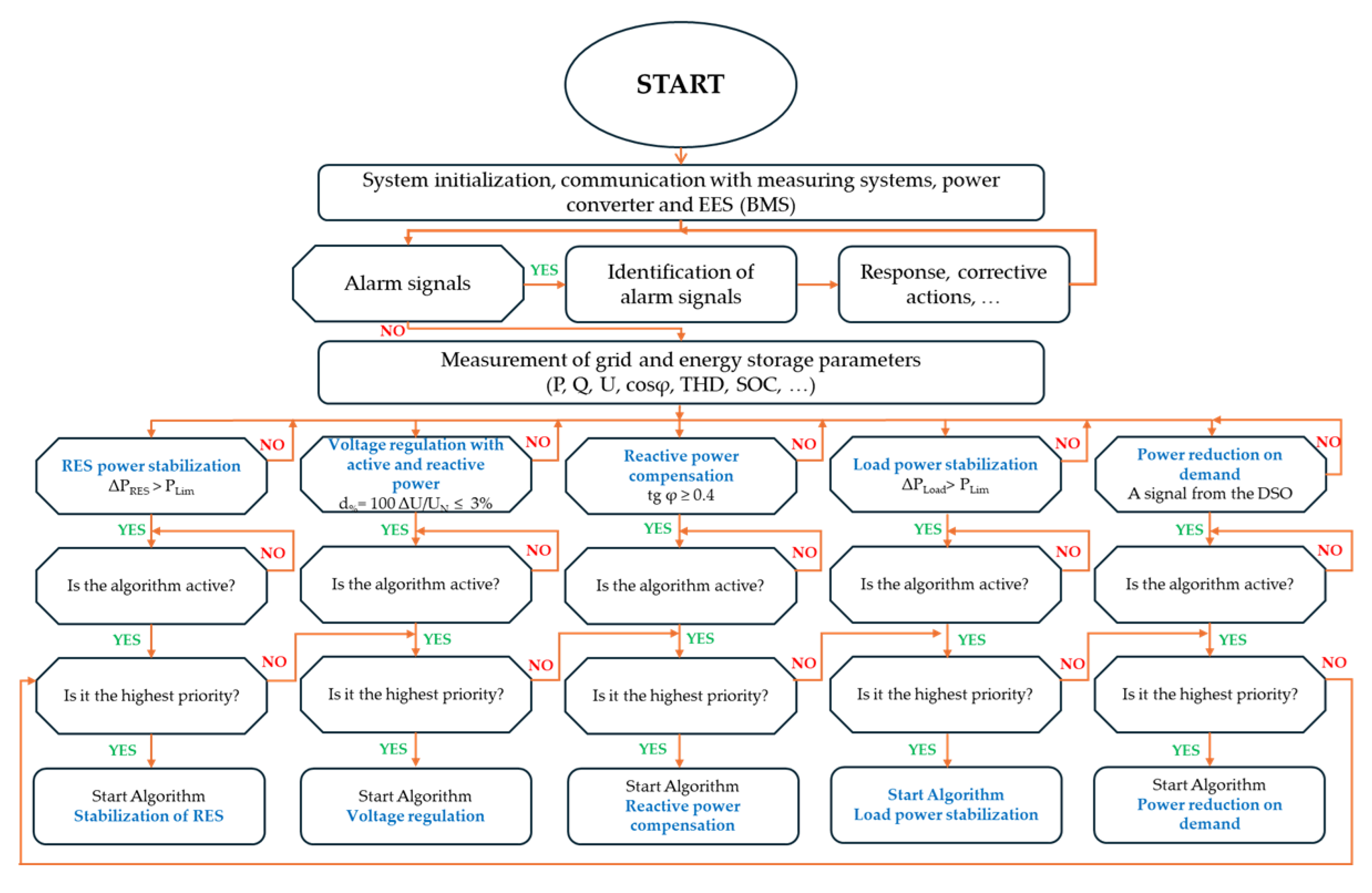
Figure 1.
The part of the control algorithm concerning system initialization, alarm verification, algorithm selection, and priority assignment is shared among all system services and does not change during runtime. Similar modular control concepts have been explored in the literature on hybrid systems and energy storage integration [
22,
23]; in our implementation, this structure has been adapted to a prioritized, multi-service framework. A more detailed representation of the diagram in
Figure 1 is shown in
Figure 2.
Figure 2 outlines the control system’s decision-making framework, where the choice of a specific energy management strategy is based on real-time system parameters. The process begins with data acquisition from the smart meter and inverter, providing three key inputs: the battery’s State of Charge (SoC), the power exchanged with the grid (Pgrid), and the current photovoltaic (PV) generation. These values are continuously monitored and serve as inputs to the decision block. The algorithm evaluates these inputs against predefined thresholds to determine the operational context of the system. For example, low SoC and high PV generation may indicate an opportunity for energy storage, while high Pgrid export with full SoC suggests curtailment or load-shifting needs. Based on these contextual assessments, each of the five predefined control strategies is assigned a dynamic priority score. The control system then selects the strategy with the highest priority score for execution. This process is repeated in real-time, allowing the system to adapt dynamically to fluctuations in demand, production, and storage conditions. Strategies are not hard-coded for fixed use cases; instead, the system can switch flexibly among them depending on the evolving grid and storage state. The individual characteristics, optimization targets, and operational assumptions of each strategy are described in detail in
Section 2.1,
Section 2.2,
Section 2.3,
Section 2.4 and
Section 2.5.
First, the system is initialized, and the communication of the control system with the converter and energy storage is checked [
24,
25]. In the next step, alarm signals informing about emergency states are checked [
26,
27] Emergency signals can be generated both by the converter and the BMS energy storage supervision system [
28]. They can also be sent by the DSO distribution network operator. Emergency signals may originate from the converter, the battery management system (BMS), or be issued by the DSO. Similar integration strategies and control responses to external fault signals have been addressed in [
29,
30,
31,
32]. Possible emergency states that may occur in the reservoir system and actions to be taken in the event of their occurrence should be defined in the future. In the absence of emergency states, the measurement data is read out [
33]. When certain limit values are exceeded, e.g., power fluctuations ΔPRES or ΔPLoad, a voltage level or power factor, or when a signal is received from the distribution grid operator, the activation of a given control algorithm is checked, and thus the possibility of running a given system service. Because not all system services can be performed by a given energy storage unit due to technological or operational limitations, the algorithm must include mechanisms to identify which services are currently feasible. The importance of such active/inactive state differentiation based on system capabilities has been discussed in [
34,
35,
36]. Each energy storage technology offers specific possibilities but also has technological limitations. Therefore, a specific storage system will not always be able to perform all the planned system services, but only those allowed by the energy storage used and its operational parameters.
In practice, a single energy storage unit is often not capable of delivering multiple system services simultaneously due to technological constraints such as converter ratings, state of charge (SoC), or response time. To address this, a prioritization mechanism has been implemented as part of the control architecture.
Each control algorithm is assigned a fixed priority level reflecting its importance for maintaining grid stability. For example, voltage regulation is typically ranked highest due to its immediate impact on power quality and end-user safety. Services like reactive power compensation or load power smoothing receive lower priorities unless specifically triggered by the distribution system operator (DSO).
During real-time operation, the control system continuously monitors key indicators such as voltage deviation, power fluctuation levels, power factor, and SoC. When one or more service thresholds are exceeded, the system selects and activates only the highest-priority algorithm whose execution is technically feasible under current conditions. Lower-priority services are temporarily disabled to avoid conflicts or overloading the system.
This dynamic approach ensures that the energy storage unit always supports the most critical network function available at any given moment while remaining within safe and efficient operating limits.
2.1. Algorithm RES Power Stabilization
The algorithm for RES power stabilization is designed to mitigate fluctuations in the output of renewable energy sources such as photovoltaic or wind installations. It is triggered when the change in power output from the RES (ΔPRES) exceeds a predefined limit (PLim), i.e., ΔPRES > PLim. Once activated, the algorithm calculates a power compensation value (Pcomp) intended to smooth the total power injected into the grid. This compensation is provided by the energy storage system (ESS), which either absorbs excess power or injects additional power depending on the direction of the fluctuation.
A key assumption is that the storage unit has a state-of-charge (SoC) level that permits both charging and discharging. Therefore, the algorithm cannot operate if SoC reaches its upper or lower boundary (SoC = SoC
max or SoC = SoC
min). If the SoC and converter limits are within acceptable ranges, the algorithm operates in real time and prevents fast RES power changes from being transferred to the grid, enhancing voltage stability and predictability at the connection point. The logic of this algorithm is illustrated in
Figure 3.
The structure presented in
Figure 3 reflects a step-by-step logic where each decision block corresponds to a clearly defined condition based on real-time system parameters. The flowchart includes checks for energy storage readiness, the magnitude and dynamics of RES power fluctuations, and time constraints that ensure system responsiveness without overreaction. Although the algorithm operates automatically, each block follows interpretable rules grounded in measurable quantities. Before initiating the RES power stabilization process, the state of charge (SoC) of the energy storage system is evaluated. Taking into account the operating constraints of the storage unit (minimum and maximum SoC levels), it is assumed that the required SoC range for executing the stabilization algorithm is between 60% and 65% of the maximum SoC capacity, i.e., 0.6·SoCmax < SoC < 0.65·SoCmax. This operating window enables the system to both absorb and supply power.
If SoC > 0.65·SoCmax, the storage discharges at power PDCH until the acceptable SoC level is restored. If SoC < 0.6·SoCmax, the storage is charged at power PCH. Once the target SoC level is reached, the RES power stabilization algorithm is initiated.
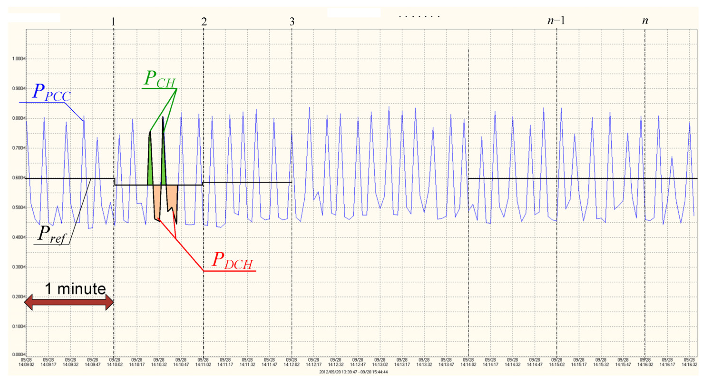
The “RES power stabilization” algorithm functions as a follow-up control system [
37], in which the controlled variable—namely, the power maintained at the Point of Common Coupling (P
CC)—follows a setpoint that evolves in a non-deterministic manner. The objective of the controller is to track the setpoint variations [
38]. The algorithm maintains a constant power value (P
ref) at the P
CC during one-minute time windows (t
1). The reference power for the current interval is calculated as the average RES power measured during the preceding interval.
At time
t1, the difference between the power generated by the RES source, measured at the PCC point (
PPCC), and the power Pref, is determined. The difference between
Pref and P
PCC is covered from the energy storage. The algorithm also takes into account the maximum allowable power change Δ
Pref (2.1.2), so as not to have a negative impact on the flicker Pst (2.1.3). After the time t1 has elapsed, the power Pref is determined again for the next period.
where:
SkQ—short-circuit power at the PCC connection point.
Depending on the type of energy storage used, operating procedures may be included in the control algorithm, if required.
2.2. Algorithm Voltage Regulation with Active and Reactive Power
The voltage stabilization algorithm operates in a manner analogous to the power stabilization algorithms [
39,
40]. Voltage fluctuations in power systems are primarily caused by variations in load demand and voltage drops along feeders and transformers [
41,
42,
43]. The key distinction between voltage and power stabilization lies in the need to determine the amount of power—active and/or reactive—that must be supplied or absorbed by the energy storage system to achieve the desired voltage correction at the Point of Common Coupling (PCC) [
44].
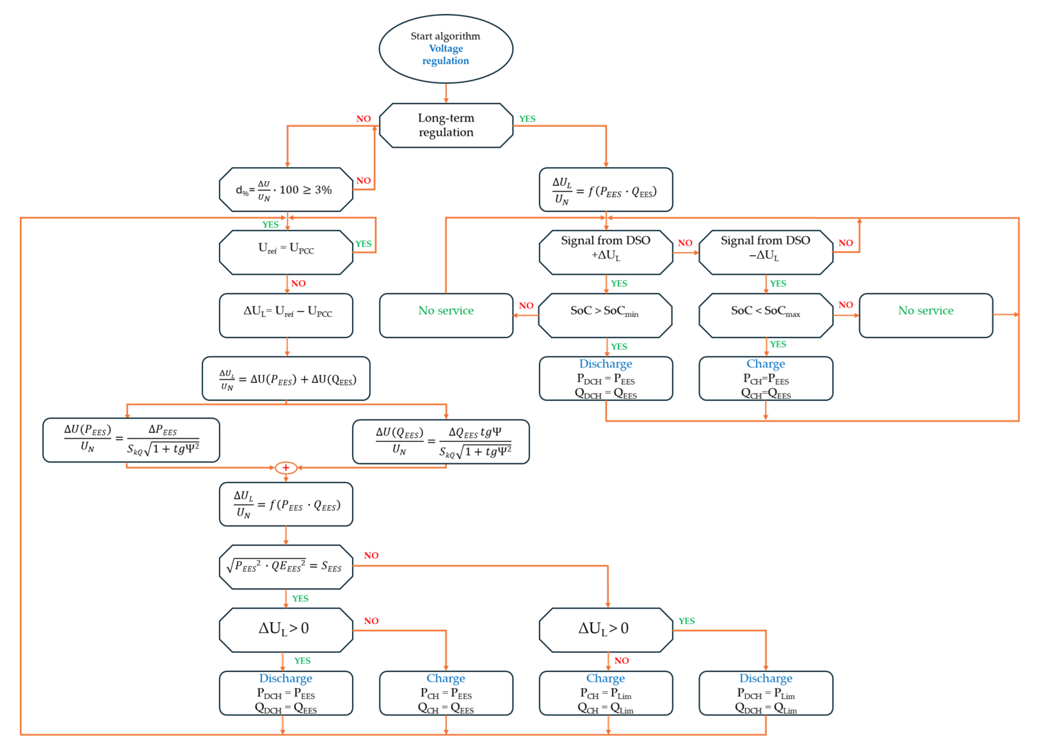
To perform this function, accurate information on the short-circuit impedance parameters at the energy storage connection point is required. The control structure of the voltage regulation algorithm using active and reactive power is presented in
Figure 4. In the initial step, the algorithm selects either the short-term or long-term regulation mode. The selection can be triggered automatically or by an external control signal from the Distribution System Operator (DSO).
2.2.1. Short-Term Control
The algorithm of short-term voltage control with active and reactive power begins to operate when the limit value of the relative voltage change (d%) at the connection point is exceeded.
where: ∆
U—voltage change,
UN—nominal voltage.
The voltage regulation algorithm illustrated in
Figure 4 is triggered in response to long-term deviations in voltage levels or control signals received from the Distribution System Operator (DSO). It evaluates whether the deviation ΔU
t/U
N exceeds the accepted range (±3%), and if so, determines whether corrective action is required. Depending on the direction and source of the voltage deviation (either local measurement or DSO signal), the algorithm assesses the available state of charge (SoC) of the storage system and verifies whether charging or discharging is feasible. It then computes the required active and reactive power contributions to restore voltage to nominal values. The selection of charging or discharging, as well as the allocation of active and reactive power (P and Q), is based on the relationship between power injection and its impact on the voltage level, taking into account the inverter’s capability and control constraints. This control logic ensures that the storage system supports voltage stability in coordination with the DSO, while maintaining safe operational limits.
If the relative change in voltage at the connection point is 3% or more, the voltage setpoints are compared with those measured at the connection point of the PCC. As in other algorithms, it is possible to enter here the insensitivity zone of the control system, in the area of which the difference (control deviation) between the set value (
Uref) and the measured value (
UPCC) will not result in the control process. If the set and measured values differ from each other—the voltage correction value Δ
UL is determined.
Since the voltage Δ
UL is in fact the effect (voltage response) of the forced flow of active power (
PEES) and reactive power (
QEES) charge/discharge by the storage system, in order to correctly determine the Δ
UL correction, it is necessary to know the short-circuit impedance at the connection point of the energy storage.
where: Δ
PEES—active power of the electrical energy storage, Δ
QEES—reactive power of the electrical energy storage.
In order to obtain the maximum possible range of voltage changes Δ
UL, and thus the control range, the algorithm must determine the active power Δ
PEES and the reactive power Δ
QEES of the storage system for voltage regulation. The relative voltage change caused in the line due to the active and reactive power flow of the storage system is defined by the relationship.
where:
SkQ—short-circuit power at the connection point, tg
Ψ—tangent of the short-circuit impedance angle at the connection point. This equation describes how voltage deviation at the PCC depends jointly on changes in active and reactive power provided by the energy storage system. It shows that the total effect can be viewed as the sum of two components, each corresponding to one type of power variation, which supports more precise voltage control.
On this basis, the algorithm determines the relative voltage change resulting from the active power (8) and reactive power (9) of the storage system.
Based on (8) and (9), the characteristic is determined as the relative change in voltage as a function of the active and reactive power of the storage system.
In the next step, the algorithm checks whether the determined active and reactive powers do not exceed the apparent power (
SEES) at which the converter with the energy storage is to operate.
If the above condition is met, the storage system will work with the determined active and reactive power. If this condition is not met and the square root of the active and reactive power exceeds the apparent power of the converter, the determined active and reactive powers will be limited to the values of
PLim and
QLim, respectively. A two-threshold limitation control scheme designed to manage battery peak power in substation environments has shown effectiveness in such constrained conditions [
45]. The algorithm will be executed cyclically until the set voltage does not differ from the voltage at the PCC point.
2.2.2. Long-Term Regulation
The section of the algorithm responsible for long-term voltage regulation using active and reactive power also requires precise knowledge of the short-circuit parameters at the PCC connection point to function correctly [
46,
47]. In this case as well, it is essential to define and account for the relationship between power flow and the resulting voltage change.
Upon receiving an operator signal requesting a voltage increase (+ΔU
L), the energy storage’s state of charge (SoC) is verified [
48,
49,
50]. Because this function involves long-duration regulation, the storage must be sufficiently charged. A higher SoC allows the service to be delivered for a longer period. Conversely, a low SoC level is necessary for responding to a voltage decrease request (−ΔU
L); the lower the SoC, the longer such a service can be sustained. If the SoC conditions are met, the system begins operating using the active and reactive power values calculated on the basis of the appropriate relationship.
2.3. Reactive Power Compensation
Reactive power compensation in electrical networks can be implemented using different methods, depending on the location of the compensating device within the system [
51,
52]. These include local, group, and central compensation strategies. Local compensation involves direct interaction between the compensator and the individual load. In contrast, group and central compensation target multiple loads, either by compensating a group of receivers or by operating at the busbars that supply power to all devices with low power factors.
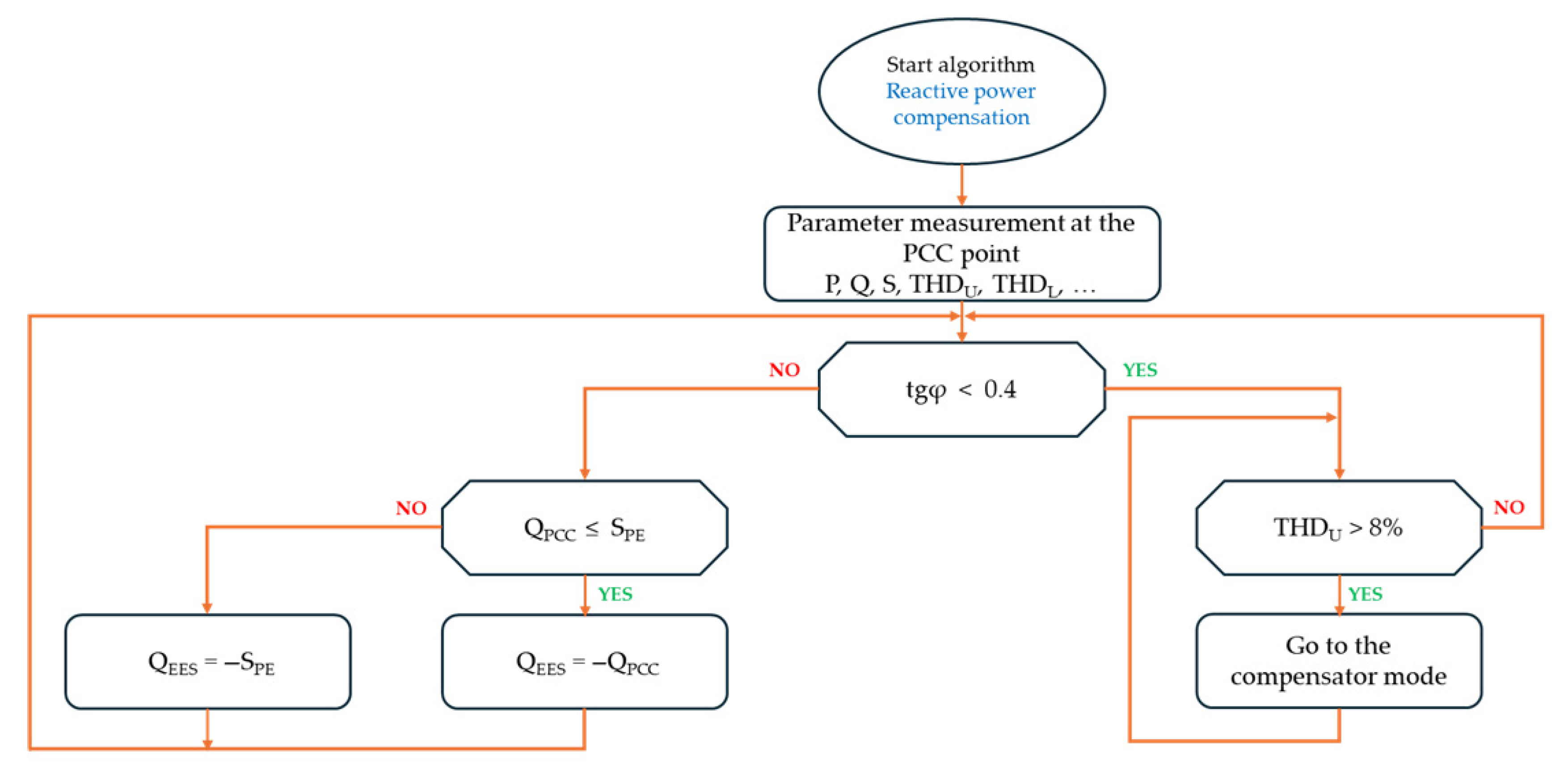
The operation of the “reactive power compensation” algorithm is illustrated in
Figure 5. The first step involves measuring the electrical parameters at the connection point of the storage system. These include active power (P), reactive power (Q), apparent power (S), power factor, and the total harmonic distortion of the voltage (THDU).
After completing the measurements, the algorithm evaluates whether the reactive power exceeds acceptable levels. If the power factor (tgφ) surpasses the threshold value (tgφ > 0.4), the system calculates the required reactive power output QEES that the storage system must supply for compensation. Prior to this, the algorithm verifies whether the calculated reactive power remains within the limits of the converter’s apparent power (SPE). If this limit is exceeded, the reactive power output is restricted to the converter’s maximum capacity.
If the measurements indicate that the power factor does not exceed the threshold (tgφ < 0.4), the algorithm proceeds to analyze the voltage waveform for harmonic distortion. If the total harmonic distortion (THDU) is found to exceed the allowable limit (THDU > 8%), the converter enters active harmonic compensation mode.
2.4. Load Power Stabilization
Power fluctuations in the power system are caused not only by renewable sources but also by dynamic load changes. Electric drives with the so-called “Hard start”, resistance and induction welders, and welding machines are the so-called restless loads [
53,
54]. These loads consume significant power in a short time, which causes abrupt power fluctuations with high dynamics. The algorithm of “Load power stabilization” in its operation is very similar to the algorithm for stabilizing the power of renewable sources (
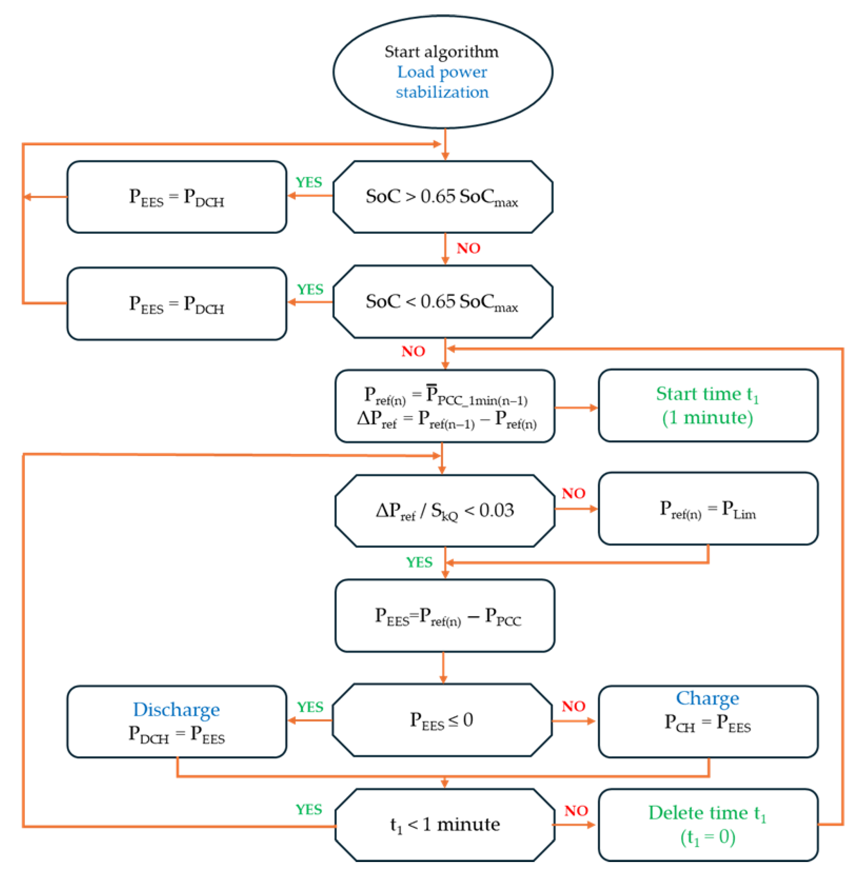
Figure 6). In both cases, it is necessary to keep the SoC of the reservoir at a level that allows for both energy collection and return.
At the initial stage of the algorithm, the energy storage system is brought to readiness by adjusting its state of charge (SoC) to the required range: 60–65% of its maximum capacity (0.6 SoC
max < SoC < 0.65 SoC
max). Next, the algorithm calculates the average load power over a one-minute interval. This average becomes the reference power level, which the storage system will aim to maintain during the subsequent minute. The algorithm manages the operation of the storage system to keep the power at the connection point (PCC) as constant as possible, maintaining the reference value (P
ref) in one-minute cycles. The functional concept of the algorithm is illustrated in
Figure 7.
This illustrates how the storage system dynamically adjusts to load spikes, compensating deviations within a predefined tolerance band to ensure power quality. The reference power is calculated using the average power variation observed during the preceding time interval.
The power at which the storage system should operate is calculated using the corresponding functional relationship.
Similar to the RES power stabilization process, the load power stabilization algorithm continuously monitors changes in reference power ΔPref for rapidly varying loads. If the defined criteria are not fulfilled, the increase in ΔPref is constrained accordingly.
where
,
SkQ—short-circuit power at the PCC connection point.
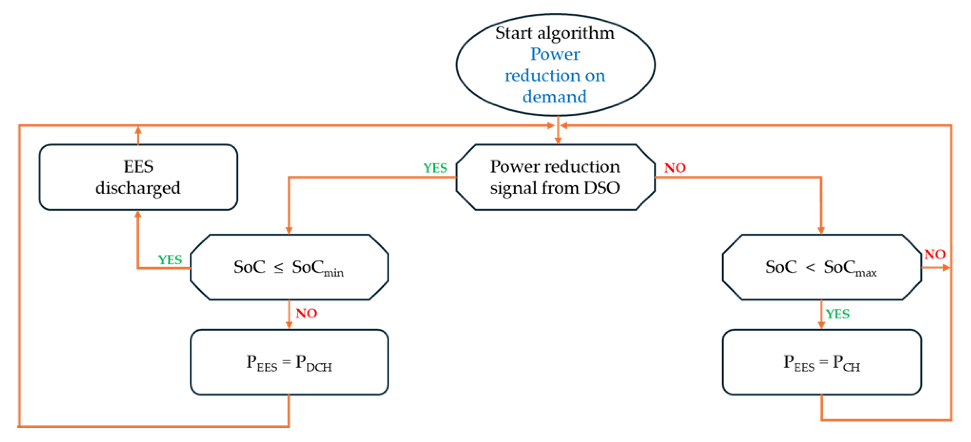
2.5. Power Reduction on Demand
The “power reduction on demand” algorithm is activated in response to a control signal issued by the distribution system operator (DSO) [
55,
56]. When power demand increases within the network, the operator may request the energy storage system to begin discharging power into the grid. It is important to note that the storage system must be adequately prepared in advance to provide this service. Such preparation involves reserving sufficient discharge capacity and ensuring that the storage has been pre-charged. From the perspective of grid management, the optimal scenario is to charge the storage system—using power PCH—during low-demand periods (energy valleys) or over longer intervals at reduced power. The process flow of the power reduction on demand algorithm is presented in
Figure 8. Its execution is triggered by a signal from the DSO’s control system.
Upon receiving a power reduction signal from the DSO, the algorithm first checks the current state of charge (SoC) of the energy storage system. If the SoC is below or equal to the minimum threshold (SoC ≤ SoCmin), the system flags the storage as depleted and temporarily disables the discharging function. The SoC level is monitored continuously throughout the process. If SoC > SoCmin, the energy storage discharges at a predefined power level (PDCH) to support the grid.
Conversely, if no reduction signal is active and the SoC is below the maximum threshold (SoC < SoCmax), the system switches to charging mode, operating at power PCH. This ensures the storage unit is adequately prepared for future grid support requests.
The control logic supports a fast and repeatable response to demand signals while maintaining SoC levels within safe operational bounds.
3. Selected Experimental Results
Five prototype energy storage units, each with a rated power of 100 kW and utilizing different storage technologies, were developed to deliver system services in low-voltage (LV) networks. The core control algorithms for these systems are described in this article. Key technical parameters of these prototypes are listed in
Table 2. The technologies used include the following: EDLC—Electric Double-Layer Capacitors; LIC—Lithium-Ion Capacitor; LFP—Lithium Ferro Phosphate; LTO—Lithium Titanate Oxide; and VRLA—Valve Regulated Lead Acid.
Considering investment costs, the number of full charge/discharge cycles, and overall system efficiency, the Levelized Cost of Energy (LCOE) for each storage technology was calculated using the following formula:
All of the prototypes are rated at 100 kW and are equipped with four-quadrant power electronic converters. Each converter consists of two 50 kW inverters operating in parallel [
57]. These inverters utilize SiC technology and incorporate galvanic isolation through a 25 kHz high-frequency transformer link.
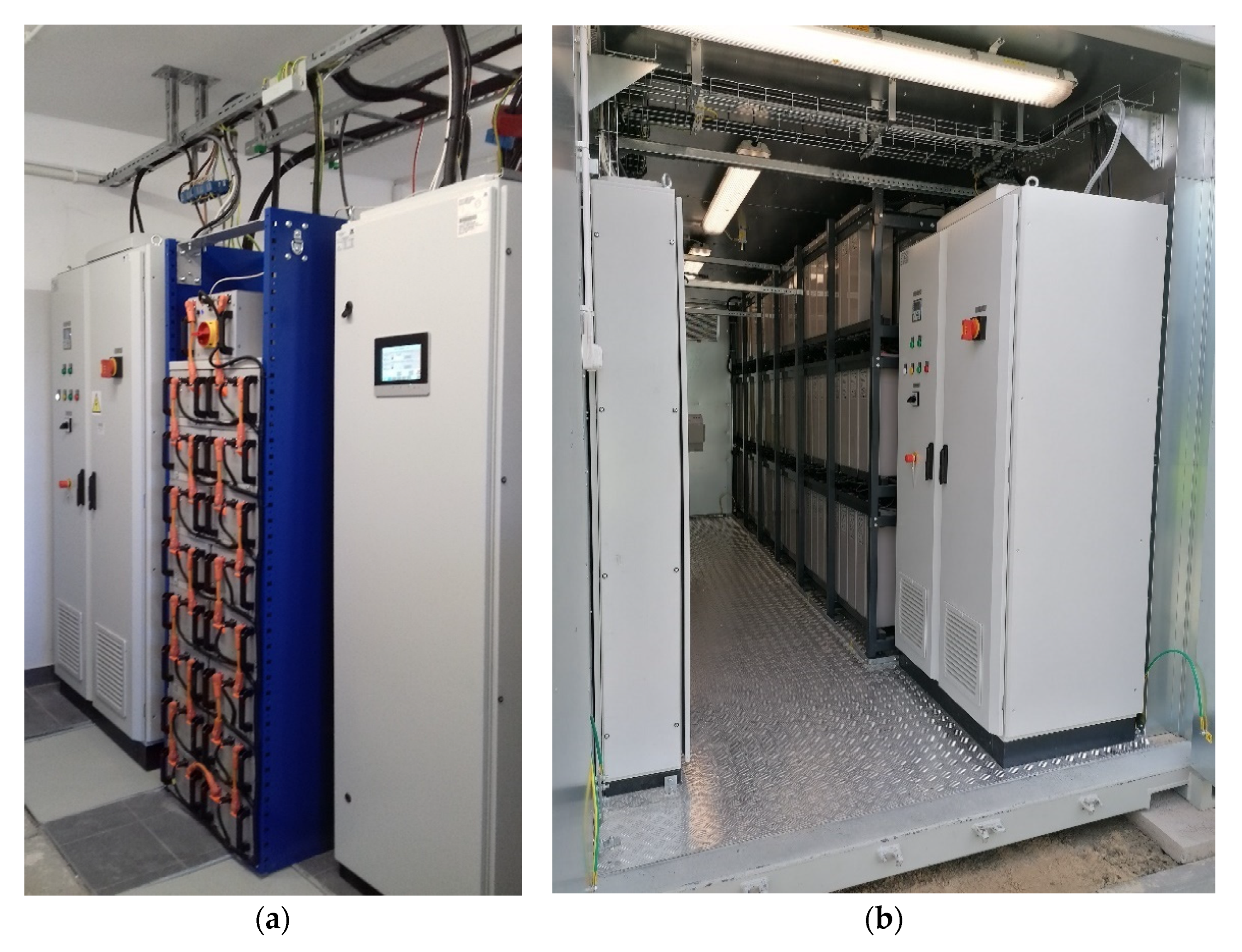
This article presents selected experimental results from two energy storage prototypes utilizing LTO and VRLA technologies. The LTO-based prototype is shown in
Figure 9a, and the VRLA-based prototype is depicted in
Figure 9b.
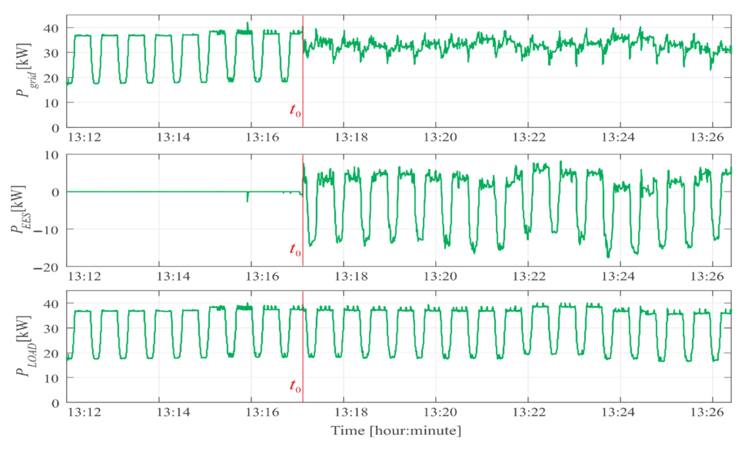
For the LTO system, test results related to load power stabilization are discussed [
58]. The tests were conducted using a Fluke 437-II Network Parameter Analyzer. In the experiment, a single 18 kW load was alternately switched on and off in one-minute intervals. The total network load profile also included background loads from the local grid. The results are illustrated in
Figure 10. The stabilization algorithm was activated at time t
0. At that moment, the energy storage system had been pre-set to a state of charge between 0.6 and 0.65 SoCmax.
Following activation of the algorithm (as shown in
Figure 6), the power drawn from the grid remained near 35 kW, with low-frequency fluctuations of up to 10 kW. When the grid load was lower than the previously calculated average reference power Pref(n − 1), the storage system absorbed power from the grid (P
EES with a “+” sign), thereby keeping the total power at the reference level. Conversely, when the load power exceeded Pref(n − 1), the storage system discharged (P
EES with a “−” sign), feeding power back into the grid.
These results indicate that in cases of abrupt load changes, full compensation is not achieved.
This reflects broader challenges in validating control algorithm performance in real-time systems, which have been documented in comparative reviews of verification methodologies in power electronics [
59]. This limitation stems from the measurement system used in the prototype, which has only a 250 ms data acquisition time. Such latency in measurement and communication is too high to enable effective stabilization of rapidly fluctuating loads.
The next set of experimental results presented in this article pertains to the operation of the voltage regulation algorithm using both active and reactive power (
Figure 4), implemented with a VRLA-based energy storage system (
Figure 9b).
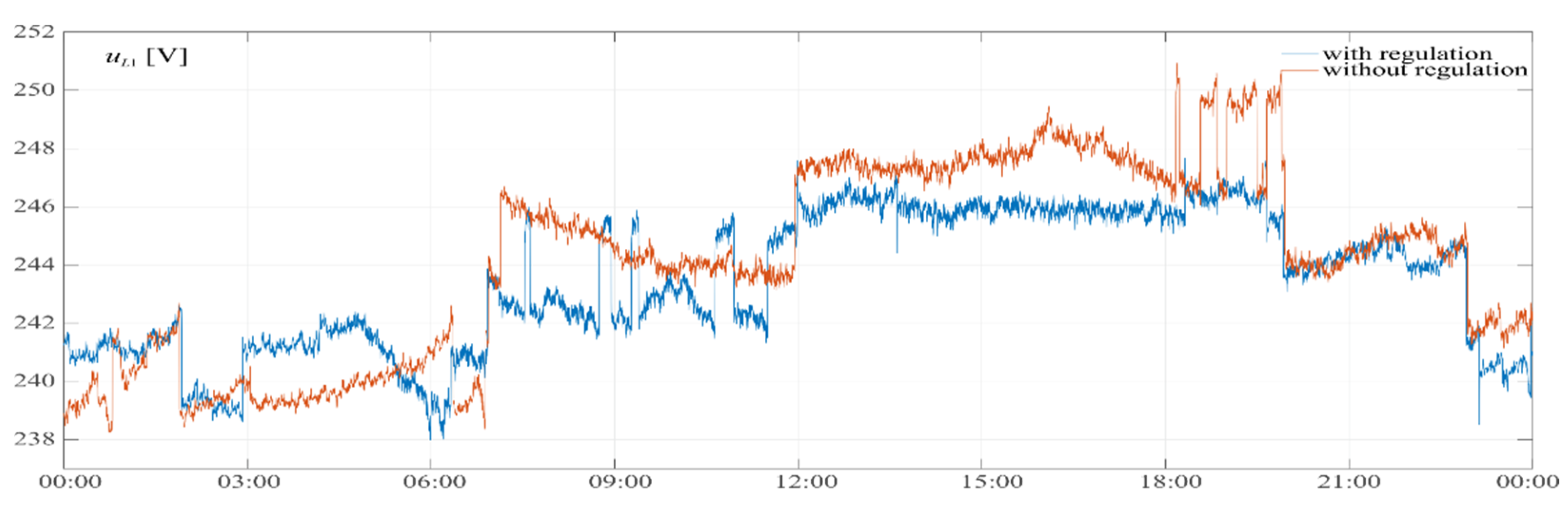
Figure 11 illustrates the time-based voltage profiles recorded on a single phase, with and without the activation of the regulation function using the VRLA prototype. The measurements were conducted on the same weekday, one week apart, allowing for a fair comparison of voltage variations at the installation point.
The control system maintained the network voltage within a predefined range—an upper limit of 246 V and a lower limit of 241 V. These boundaries are clearly reflected in the time-domain plots. Some instantaneous voltage values exceeded the limits due to the dynamic response characteristics of the control algorithm. However, a noticeable reduction in voltage fluctuation is observed when the regulation system is active. In contrast, without the voltage control service enabled, voltage peaks exceeded 250 V, while the minimum values dropped to 238 V. The remaining algorithms—RES power stabilization, reactive power compensation, and power reduction on demand—have not yet been experimentally validated in physical prototypes. Their implementation has so far been limited to simulation environments and system-level integration phases. Full hardware testing is planned for future stages of development.
The experimental validation presented in this study confirms the feasibility of implementing the proposed control algorithms for specific system services under real-world operating conditions. The results demonstrate that the control system successfully responds to fluctuations in load and voltage, maintaining performance within expected parameters.
However, it is important to emphasize that the purpose of this stage of research was not to benchmark the proposed algorithms against existing strategies. A fair and conclusive performance comparison would require deploying alternative algorithms under identical hardware and network conditions, which was beyond the scope of this experimental implementation. Future work will include simulation-based and experimental analyses aimed at assessing the relative advantages of the proposed control logic in terms of stability, responsiveness, and cost-effectiveness.
3.1. Conceptual Simulation Framework for Control Algorithm Validation
In order to address the limited scope of hardware-based validation within this study, a conceptual numerical simulation was developed to assess and compare the operational performance of all five proposed control algorithms for battery energy storage systems (BESS). This virtual testbed was constructed using typical technical specifications of residential lithium-ion storage units and standard operational scenarios, enabling consistent and repeatable evaluation of each method under identical boundary conditions.
Simulated Battery System Parameters:
Battery technology: Lithium Iron Phosphate (LiFePO4)
Nominal capacity: 10 kWh
Nominal voltage: 48 V
Maximum charge/dischargecurrent: ±100 A
Internal resistance (simplified R model): 0.05 Ω
Depth of discharge (DoD): 90%
Usable State of Charge (SoC) range: 10% to 100%
Maximum system power: ≈4.8 kW
Environmental and Operational Assumptions:
Simulation time horizon: 24 h with 1 s resolution (86,400 timesteps)
Load and PV generation profiles based on publicly available residential data sets (normalized to the system scale)
Ideal operating conditions (no thermal degradation, perfect switching, and 100% battery health assumed)
Ambient temperature constant; thermal effects and inverter dynamics not modeled
3.2. Simulation Procedure
Each algorithm was implemented as an autonomous control module, receiving real-time input data (SoC, load, PV generation) and producing output commands: charging, discharging, or idle. At each time step, the system state was updated according to the control decision, and performance metrics were computed. The comparative analysis was conducted under identical input profiles for all algorithms. The following performance indicators were recorded:
- −
Response time: the average time required for the control system to react to a triggering condition;
- −
Energy efficiency: defined as the ratio of usable output energy to total energy processed by the system;
- −
Control quality: a heuristic score reflecting SoC stability, switching frequency, and avoidance of overload events.
The simulation results provide a conceptual overview of the expected operational characteristics of each algorithm. Although these outcomes do not represent empirical measurements, they offer a transparent and standardized framework for benchmarking performance under controlled and replicable conditions. Full-scale empirical validation is intended as a direction for future research.
An AI-based tool was employed to support the conceptual simulation of control algorithms, enabling the generation and evaluation of system behavior scenarios within a virtual battery storage environment.
Summary of conceptual performance characteristics of five control algorithms for battery energy storage systems, based on numerical simulation. The results include estimated response time, energy efficiency, control quality, and implementation complexity under standardized virtual conditions.
| Algorithm | Simulation Validated | Control Quality (0–5) | Response Time (s) | Energy Efficiency (%) | Implementation Complexity |
| Naive SoC Rule | ✓ | 2 | 60 | 88 | Low |
| Price Threshold | ✓ | 3 | 45 | 91 | Medium |
| Cycle Balancing | ✗ | 4 | 30 | 94 | Medium |
| Frequency-Based | ✗ | 5 | 15 | 97 | High |
| Adaptive Forecasting | ✗ | 4 | 25 | 95 | High |
| | Simulation Validated—Indicates whether the algorithm was verified using real hardware (✓) or not (✗). Control Quality—Heuristic score reflecting system stability, SoC behavior, and switching performance. Response Time—Average time required for the control system to respond to triggering events. Energy Efficiency—Ratio of usable output energy to the total energy cycled through the system. Implementation Complexity—Estimated level of effort required to implement the control method in practice. |
The comparative results indicate that frequency-based and adaptive forecasting algorithms demonstrate superior control quality and energy efficiency under simulated conditions, albeit with higher implementation complexity. In contrast, simpler rule-based strategies exhibit slower response times and reduced overall performance, though they may offer easier integration in low-cost systems.
To complement the experimental and simulation results, the following section provides a brief overview of how the control algorithms may behave under varying network conditions and their potential resilience to common disturbances.
3.3. Robustness and Scalability Considerations
Although the proposed control algorithms were evaluated under idealized simulation and limited experimental conditions, their architecture is inherently modular and adaptable to diverse grid scenarios. Algorithms relying on frequency signals (e.g., Frequency-based) or adaptive forecasts are particularly responsive to high short-term volatility, making them suitable for environments with significant renewable energy fluctuations.
In rural networks with lower infrastructure density, the slower response of simpler rule-based methods (e.g., Naïve SoC Rule) may still be acceptable due to reduced variability and fewer switching events. Conversely, in dense urban grids, control-responsive algorithms may offer better grid support under dynamic load and generation profiles.
While fault scenarios and inverter-level disturbances were not explicitly modeled, the hierarchical structure of service prioritization and the inclusion of SoC and power thresholds provide a baseline level of robustness to input anomalies. Future extensions will include scenario-based testing and disturbance injection to more rigorously assess algorithmic resilience.
4. Conclusions
The article discusses a set of dedicated control algorithms designed for Electrical Energy Storage (EES) systems to support the delivery of specific system services in low-voltage (LV) power networks. Five types of services were considered: stabilization of renewable energy output, voltage regulation using both active and reactive power, compensation of reactive power, stabilization of fluctuating loads, and power curtailment upon request. These services aim to enhance the quality parameters of electricity supplied through LV distribution grids.
The paper also presents the overarching structure of the control algorithms and outlines the initial operating assumptions. Since an individual energy storage installation can typically support only a limited number of services (usually up to five), the algorithms are assigned specific priorities. When multiple threshold conditions are exceeded simultaneously—such as THDU and ΔPPCC—and the system cannot execute more than one service at once, the algorithm with the highest priority will be activated. The internal logic and functionality of each algorithm have been described in detail throughout the article.
Although the proposed algorithms are presented in a modular and generalized structure, they form a coherent framework for managing system services provided by energy storage systems in low-voltage distribution networks. A key innovation lies in the dynamic prioritization approach, which adjusts service execution based on the technical condition of the storage system and real-time grid conditions.
The experimental results confirm the feasibility of the proposed algorithms under real operating conditions, but further development is needed. Future research will include comparative simulations with other control strategies and extended validation across all five system services.
One of the practical advantages of the presented control logic is its scalability—both in terms of compatibility with different storage technologies and its applicability to various distribution network topologies. The authors recommend that such control logic be tested in pilot implementations, particularly in areas with high renewable energy penetration.
Further work will also explore the impact of control intervention frequency on the lifetime and economic viability of energy storage systems.
The proposed algorithms were developed as part of the research project “Innovative energy storage system services increasing the quality and efficiency of electricity use”. The article also briefly discusses the project’s prototype energy storage systems, based on various technologies (
Table 2), designed to deliver selected system services in the LV power grid. Experimental results for the implementation of the proposed algorithms using LTO and VRLA-based EES prototypes are presented. These results confirm the feasibility of delivering the specified system services in LV power electronics networks using the proposed control algorithms.
Detailed results from the individual algorithm evaluations will be published in future scientific studies. Further simulation-based [
60] and experimental research on the existing prototypes will be necessary to assess how the operational parameters of EES systems affect the durability and performance of different energy storage technologies.
It should be clearly stated that, at the current stage, only two out of the five proposed control algorithms—load power stabilization and voltage regulation—have been experimentally validated using real hardware prototypes. The remaining three algorithms (RES power stabilization, reactive power compensation, and power reduction on demand) have not yet undergone full hardware validation and are presently limited to simulation environments and system-level design. Experimental testing of these three algorithms is planned for future development stages.
In particular, future research will focus on evaluating the impact of frequent charge–discharge cycles caused by real-time control interventions on the battery’s state of health (SoH) and overall lifecycle cost. Since each service activation contributes to battery wear—especially in demanding applications such as load power smoothing and reactive power compensation—it is essential to assess the trade-off between short-term grid performance and long-term degradation. Monitoring SoH indicators and integrating battery degradation models into the control architecture will be essential to optimize service delivery while minimizing CAPEX escalation over time.
Scalability and Lifecycle Considerations
In addition to demonstrating the functional validity of the proposed control algorithms, it is essential to address their long-term implications. Frequent charge–discharge cycles initiated by real-time control interventions may accelerate battery degradation and affect the State of Health (SoH) of storage units. Therefore, the practical deployment of such control schemes at scale must account for a trade-off between maximizing grid-support functions and minimizing lifecycle impacts. Future development of the control architecture will integrate SoH monitoring and degradation-aware scheduling mechanisms. This approach aims to balance performance and longevity by adjusting service priorities based on battery condition.
Moreover, the proposed algorithms are designed with modularity and scalability in mind, making them adaptable to a wide range of low-voltage network configurations. Pilot implementations in networks with high penetration of renewables will serve as the testbed for assessing both technical feasibility and economic viability under real-world constraints.
In addition, a conceptual simulation framework was introduced to compare the performance of all five control algorithms under standardized virtual conditions. This approach enabled an initial benchmarking of control quality, response time, and energy efficiency across methods, including those not yet validated experimentally. While the results are not based on physical testing, they provide a valuable foundation for identifying strengths and limitations of each approach. Future work will focus on extending this framework with more detailed dynamic models and integrating it with ongoing hardware validation.


 ,
, 


