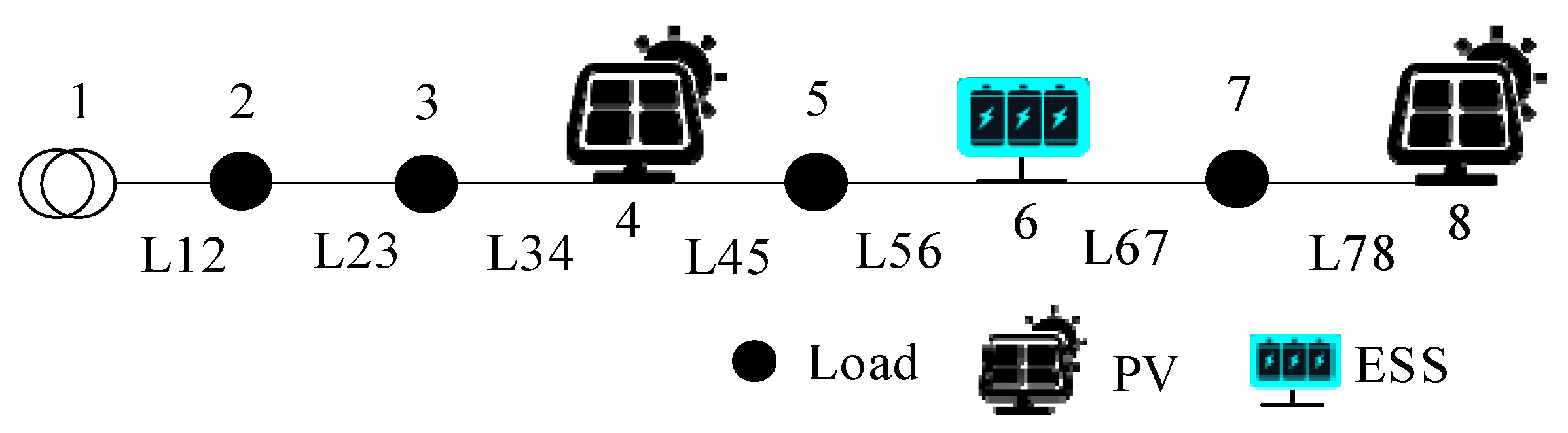
Abstract
High permeability distributed photovoltaic (PV) access to the distribution network makes it easy to cause frequent overvoltage of the system. However, the traditional centralized optimization scheduling method is difficult to meet the real-time voltage regulation requirements due to high communication costs. In this regard, this paper proposes a distributed fast voltage regulation method for energy storage systems (ESSs) in distribution networks. Firstly, to reduce the communication burden, the distribution network cluster is divided according to the electrical distance modularity index. Secondly, the distributed control model of active distribution network with the goal of voltage recovery and ESS power balance is established, and a distributed controller is designed. The feedback-control gains are optimized to improve the convergence rate. Finally, the IEEE33 bus system and IEEE69 bus system are applied for simulation. The results show that the proposed distributed optimal control method can effectively improve the voltage level of the distribution network under the condition of ensuring the ESS power balance.
1. Introduction
The exponential growth of distributed photovoltaic (PV) integration in distribution systems has emerged as a dual-faceted phenomenon, presenting both significant challenges and transformative opportunities for grid modernization. With global PV installations anticipated to surpass 1 TW capacity by 2030, modern distribution networks are confronting unprecedented operational complexities stemming from bidirectional power flows and inherent generation intermittency [1]. Although these distributed renewable energy systems offer considerable economic advantages and carbon emission reductions, their weather-dependent power output introduces substantial stochastic fluctuations in network parameters. This variability manifests particularly in frequent voltage excursions beyond statutory limits [2,3,4,5], creating critical infrastructure security concerns while constraining system-wide renewable energy penetration levels. Such operational challenges underscore the urgent need for advanced voltage regulation strategies, which have become a pivotal requirement for ensuring both grid stability and sustainable expansion of renewable energy infrastructure [6,7].
The application of new technologies has turned traditional distribution networks into smart distribution networks [8,9]. The voltage regulation strategies in distribution networks can be categorized into three primary paradigms based on communication infrastructure requirements: centralized control, localized autonomous control, and distributed cooperative control. Centralized methodologies leverage system-wide telemetry data and advanced optimization frameworks—including model predictive control (MPC) and mixed-integer nonlinear programming (MINLP)—to coordinate PV inverters, capacitor banks (CBs), and energy storage systems (ESSs) for holistic voltage management. For instance, Reference [10] demonstrates centralized coordination of distributed generation units and CBs through coupled active-reactive power optimization, achieving multi-objective voltage stabilization. Similarly, Reference [11] implements a voltage–power sensitivity matrix within a centralized optimization scheme targeting simultaneous minimization of grid losses and voltage deviations.
In contrast, localized control architectures employ autonomous decision-making based on localized measurements, sacrificing global optimality for superior response characteristics during transient voltage violations. A prevalent implementation involves PV inverters providing dynamic reactive power compensation, serving as both a rapid corrective measure and proactive countermeasure against voltage excursions [12]. This decentralized approach’s efficacy is further enhanced in hybrid configurations, as exemplified by [13], which proposes a two-tiered control paradigm: local controllers execute millisecond-timescale reactive power adjustments during voltage contingencies, while centralized optimization periodically recalibrates system-wide setpoints to maintain operational optimality.
Centralized voltage regulation architectures exhibit inherent structural dependencies on robust communication infrastructure and suffer from computational intensity due to their system-wide optimization scope. Conversely, localized control strategies, while achieving rapid response through autonomous operation, demonstrate suboptimal resource utilization stemming from their inability to coordinate geographically dispersed voltage regulation assets. Distributed control emerges as a compromised paradigm that synthesizes the benefits of both approaches—enabling cooperative optimization through neighbor-to-neighbor communication with minimized bandwidth requirements [14]. This methodology has been operationalized through various implementations: Reference [15] demonstrates distributed voltage stabilization via coordinated photovoltaic reactive power compensation coupled with active power curtailment strategies, while Reference [16] introduces an adaptive distributed framework leveraging time-varying network topology data for real-time PV power modulation. However, these approaches predominantly rely on PV generation adjustments, potentially incurring undesirable renewable energy dissipation.
Current distributed voltage control methodologies in distribution networks predominantly employ consensus algorithms, with their design frameworks primarily focusing on optimizing steady-state voltage regulation outcomes while inadequately addressing the convergence dynamics of distributed control processes. To overcome this theoretical limitation, advanced optimal control theories, such as linear quadratic optimal control, are being progressively integrated into distributed controller architecture design. Study [17] investigates voltage control mechanisms in AC microgrids, innovatively developing a robust distributed control framework based on the H∞ performance index, which effectively balances system disturbance-rejection capabilities with voltage regulation precision. Research study [18] establishes a multi-objective optimization design method for distributed secondary voltage controllers in microgrids, achieving simultaneous voltage recovery and power loss minimization through dynamic optimization of reactive power allocation strategies for distributed energy resources. For islanded DC microgrid scenarios, Reference [19] proposes a distributed secondary optimal control method that derives an optimal-state feedback-gain matrix by solving the corresponding Riccati differential equation of the microgrid system, theoretically demonstrating exponential convergence rate improvements compared to conventional PI control approaches.
The inherent structural complexity of AC distribution networks, characterized by numerous nodal points and distributed PV integration, imposes significant limitations on conventional distributed voltage control methods, which typically exhibit suboptimal dynamic response characteristics. This operational latency underscores the critical need for enhanced convergence dynamics in distributed voltage regulation frameworks to achieve rapid and precise network stabilization. To address this challenge, this paper introduces a novel multi-objective distributed voltage regulation strategy leveraging ESSs as agile voltage control actuators. The proposed methodology establishes an innovative framework that synergistically combines minimal communication overhead with robust operational stability and accelerated convergence properties. The principal scientific contributions of this research are articulated as follows:
- (i)
- The distributed control strategy for ESSs in active distribution network is proposed, where the control objectives of voltage recovery and ESS power balancing can be simultaneously achieved by utilizing only information from adjacent clustered regions.
- (ii)
- The optimization method of feedback-control gain is presented, which not only can ensure the stability of the controller but also improve the convergence speed of the distributed control strategy.
The rest of this paper is organized as follows: Section 2 introduces the voltage control principles for ESSs. Section 3 illustrates the distribution network cluster division. Section 4 demonstrates distributed controller design. Section 5 presents improved distributed controller design. Section 6 presents the simulation results, and the conclusions are discussed in Section 7.
2. Voltage Control Principles for ESSs
The ESSs eliminate the voltage off-limit by adjusting the active power flow distribution. Figure 1 shows a simple distribution network with PV systems and ESSs. Bus 1 is the root bus. Buses 2–8 are the load buses or PV buses. According to the linear power flow model, when the ESS at bus 6 outputs power ΔPess, the nodal voltage variation ΔV4 at bus 4 and ΔV7 at bus 7 can be expressed as [20]:
where RL12, RL23, RL34, RL45, and RL56 are the resistance of L12, L23, L34, L45, and L56.
Figure 1.
Diagram of a simple distribution network.
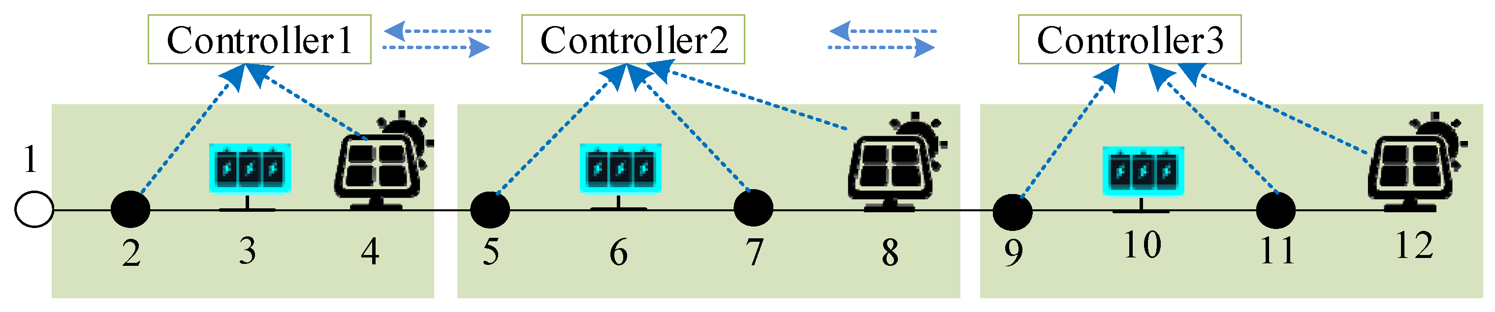
In general, when the output power of the ESS at bus i increases ΔPi, the voltage amplitude increment of bus j is:
where Rl is the resistance of branch l, is the set of branches on the path from root bus to bus I, and is the set of branches on the path from root bus to bus j. Sji is the voltage sensitivity coefficient of the nodal voltage at bus j to the nodal power at bus i.
Considering all ESSs, the voltage amplitude increment of bus j is:
where Ness is the number of ESSs.
3. Distribution Network Cluster Division
In the centralized control method, the information center collects all nodal voltage data and distributes it to each ESS controller. However, this approach imposes a heavy communication burden and exhibits low reliability following communication failures. To address the operational challenges of high nodal density and spatially concentrated voltage violations in AC distribution networks, this study develops a cluster-based distributed control strategy that strategically partitions the network into multiple electrically cohesive clusters through sensitivity-driven modularity optimization, as illustrated in Figure 1. Each cluster integrates a distributed ESS with a local controller, forming a cyber-physical control unit capable of autonomous decision-making. The control architecture operates through a dual-layer coordination mechanism: locally, each ESS controller assimilates real-time voltage measurements within its cluster via PMU-enabled state estimation, while regionally, adjacent controllers exchange normalized voltage deviation indices and ESS power parameters through a directed graph communication topology compliant with IEC 61850 standards. As shown in Figure 2, node 1 is the root node. Each ESS controller accesses voltage information from specific nodes: Controller 1 covers nodes 2–8, Controller 2 covers nodes 2–12, and Controller 3 covers nodes 5–12.
Figure 2.
Diagram of distribution network cluster division.
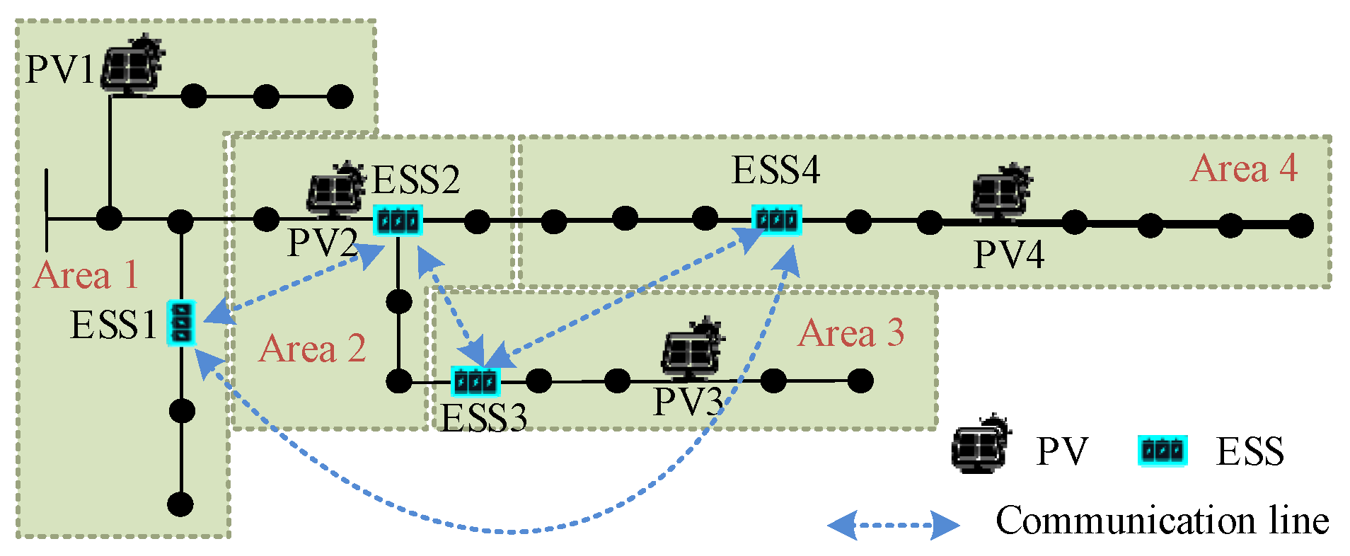
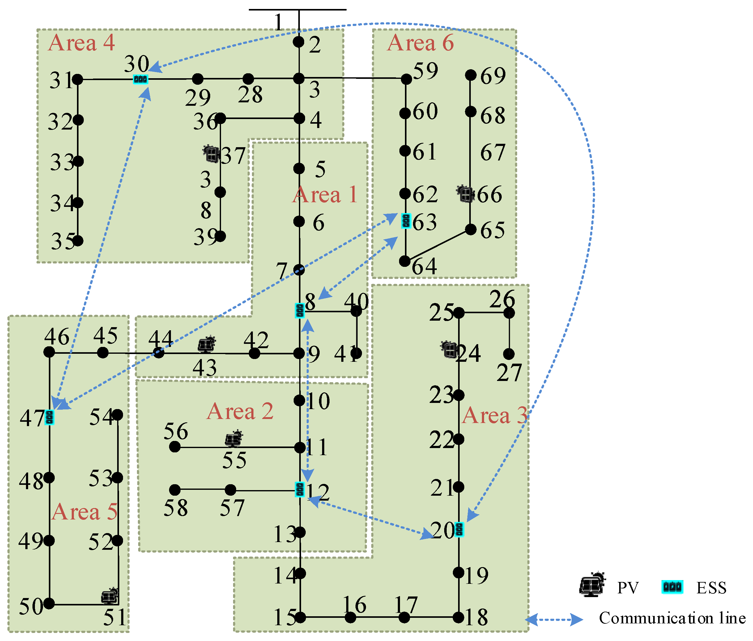
This study uses an electrical distance-based modularity index to divide distribution network clusters. According to [21], the modularity ρ is calculated as:
where is the total network edge weights, eij is edge weight between nodes i and j, and ki is sum of weights for all edges connected to node i. If nodes i and j are in the same partition, = 1; otherwise, = 0.
In this study, the edge weights are determined by electrical distance. Electrical distance is calculated using node voltage sensitivity:
where Lij is the electrical distance at node j and node i, Sin is the voltage sensitivity coefficient of the nodal voltage at bus i to the nodal power at bus n, and Nbus is the number of all buses.
Partition weights are defined using electrical distances:
where max(L) is the maximum electrical distance.
The genetic algorithm is used to minimize modularity values for optimal cluster division.
4. Distributed Control Strategy
4.1. Objective Function
PV fluctuations induce voltage deviations. To mitigate ESS over-discharge and lifespan degradation during voltage regulation, this study balances power quality with ESS protection. The control objectives include voltage restoration and ESS power balancing.
The objective of voltage regulation is to minimize the total deviation of node voltages from the rated value:
where Vi is the voltage at node i, and Vr denotes the rated voltage.
The objective of ESS power balancing is to minimize the power rate differences among ESS units:
where Pm is the output power of the m-th ESS, and Pm,max is the maximum output power of the m-th ESS.
4.2. Dynamic Model of Nodal Voltage and ESS Power Ratio
Based on the sensitivity of the node voltage to the active power of the ESS in Equation (3), the voltage dynamic model at node i during active power adjustment of the ESS can be expressed as:
where Vi(k + 1) and Vi(k) represent the voltages of node i in the (k + 1)-th and k-th control actions, respectively; ΔPm(k) denotes the active power adjustment of the m-th ESS during the k-th control interval; and Si,m is the voltage sensitivity coefficient of node i to the active power of the m-th ESS.
When the ESS active power is adjusted, the dynamic model of ESS active power becomes:
where Pm(k + 1) and Pm(k) are the power of the m-th ESS during the (k + 1)-th and k-th control intervals, respectively.
4.3. Distributed Controller Design
To achieve voltage restoration and ESS power balancing in a distributed way, a state parameter xm is introduced for the m-th ESS, following the control variable design in [18]:
where Ωm,node denotes the nodes in the cluster containing the m-th ESS and its connected clusters, Ωm,ess denotes the ESS units in the cluster containing the m-th ESS and its connected clusters, and a and b denote weighting coefficients for the two objectives.
The dynamic model of xm is derived from the voltage and power rate models:
where xm(k + 1) and xm(k) are the state deviation parameters for the m-th ESS at the (k + 1)-th and k-th control steps, and Sn,m is the voltage sensitivity coefficient of node n to the active power of the m-th ESS.
For the m-th ESS, the controller for adjusting its operating active power is:
where km is the feedback gain of the m-th ESS.
The general voltage control law for all ESS units in the distribution network is:
where , , , and is derived from Equation (13).
4.4. Controller Gain Design Method
Based on Equations (14) and (15), the discrete-time state-space model for the distributed voltage control of a distribution network with ESS power regulation is formulated as:
where K is expressed as:
In system (16), the controller gains K that critically influence the stability and convergence speed of the closed-loop system (16) are the pending variable.
For system (16), the matrix M is defined as:
For system (16), Reference [22] proves that the control system is stable if the controller gains K satisfy the following condition:
where ρ(M) denotes the spectral radius of M. For the specified controller gains K, the QR algorithm can be used to calculate the spectral radius of M.
Additionally, according to the proof in Reference [22], reducing ρ(M) by selecting suitable controller gains K can improve the control speed of the closed-loop system. To optimize the controller gain K, we minimize the spectral radius of M:
For a distribution network with fixed topology, the parameters A and B in the dynamic model (15) are known. Thus, the optimization of K can be performed offline. Since the spectral radius minimization in Equation (19) constitutes a nonlinear optimization problem, nonlinear optimization algorithms (e.g., genetic algorithms) can be employed for its solution. In this paper, the genetic algorithm is used to optimize the controller gain K, and the controller gain of each ESS consists of a complete individual. The flowchart for genetic algorithm-based controller gain optimization is presented in Algorithm 1, where NGA denotes the number of genetic algorithm generations.
| Algorithm 1: Genetic Algorithm-Based Controller Gain Optimization |
| 1: Initialize population for controller gain matrix K 2: For generation = 1 to NGA do 3: Calculate spectral radius ρ for each individual via QR algorithm 4: Assign ρ as fitness value 5: Perform genetic operations (selection/crossover/mutation) 6: End For 7: Output optimal controller gain K. |
5. Algorithm Improvement to Reduce Implementation Costs
The implementation cost of the proposed voltage control method is predominantly determined by ESS charging/discharging losses. To mitigate these losses, this paper introduces an enhanced algorithm. First, we introduce an index characterizing the relative charging/discharge efficiency of ESS units:
where is the charge/discharge power efficiency of the m-th ESS, is the charge/discharge power efficiency of the i-th ESS, and is the relative charge/discharge power efficiency of the m-th ESS.
Based on the defined relative charging/discharge efficiency of ESS units, those with higher values should be prioritized for power dispatch to reduce voltage recovery implementation costs. Consequently, the ESS power-balancing objective in Equation (9) is reformulated as follows:
where c is the weight coefficient of reducing the implementation cost.
Accordingly, the control variable in Equation (12) is defined as:
The dynamic model of xm is reformulated based on Equation (23), and the distributed controller is developed following the methodology in Section 4.
6. Numerical Simulation
6.1. Test System 1
The proposed multi-objective distributed optimization control strategy is validated through simulations conducted on an IEEE 33-node test system operating at 12.66 kV with permissible voltage limits of 0.95–1.05 p.u. The system configuration comprises four PV systems with rated capacities of 1.2 MW, 1.0 MW, 1.0 MW, and 2.0 MW installed at nodes 4, 13, 18, and 30, respectively. Four ESSs each rated at 1.2 MW are strategically deployed at nodes 5, 10, 22, and 27. The initial ESS output powers are 0. The distributed control architecture initiates communication at t = 1 s with a fixed update interval of 100 ms for coordinated operation.
Figure 3 illustrates the system topology and the corresponding cluster division results of the IEEE33 bus system. In terms of nodal voltage information, ESS1 accesses nodal voltages in Areas 1, 2, and 4; ESS2 in Areas 1, 2, and 3; ESS3 in Areas 2, 3, and 4; and ESS4 in Areas 1, 3, and 4. In terms of ESS power information, ESS1 accesses power information of ESS1, ESS2, and ESS4; ESS2 accesses ESS1, ESS2, and ESS3; ESS3 accesses ESS2, ESS3, and ESS4; and ESS4 accesses ESS1, ESS3, and ESS4. The objective function employs weighting coefficients a = 10, b = 1, and c = 0 to balance competing optimization targets. Controller parameters are optimized through a genetic algorithm implemented on the MATLAB 2016b platform, yielding the following optimized control gains for ESSs. The control gains for each ESS are shown in Table 1. This paper focuses on steady-state voltage recovery, and the transient process of voltage regulation is ignored. The nodal voltages calculated after each control action using MATPOWER’s power flow solver. In the power flow solver, the voltage convergence error is 0.00001 p.u., and the maximum iteration number is 100. For analyzing the control speed of the distributed controller, convergence is defined as the point where the voltage deviation is less than 0.0001 p.u. from the final steady-state value.
Figure 3.
Cluster division results of IEEE33 bus system.
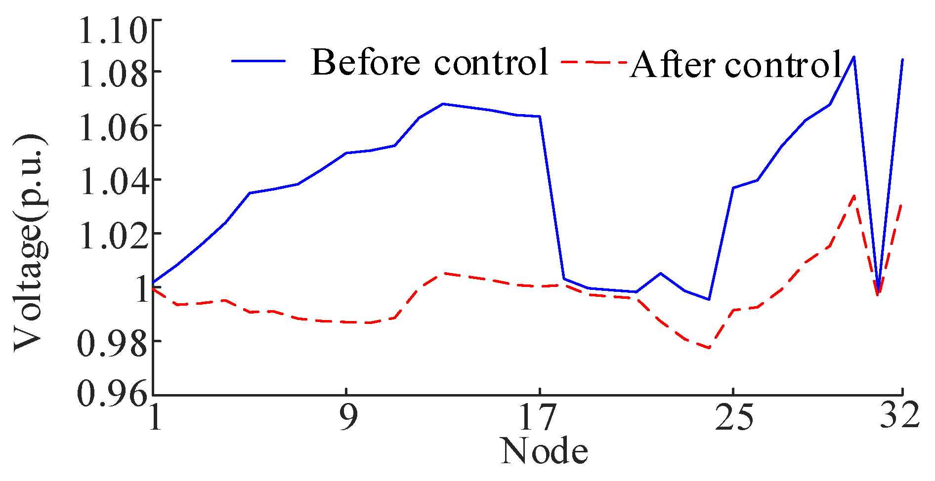
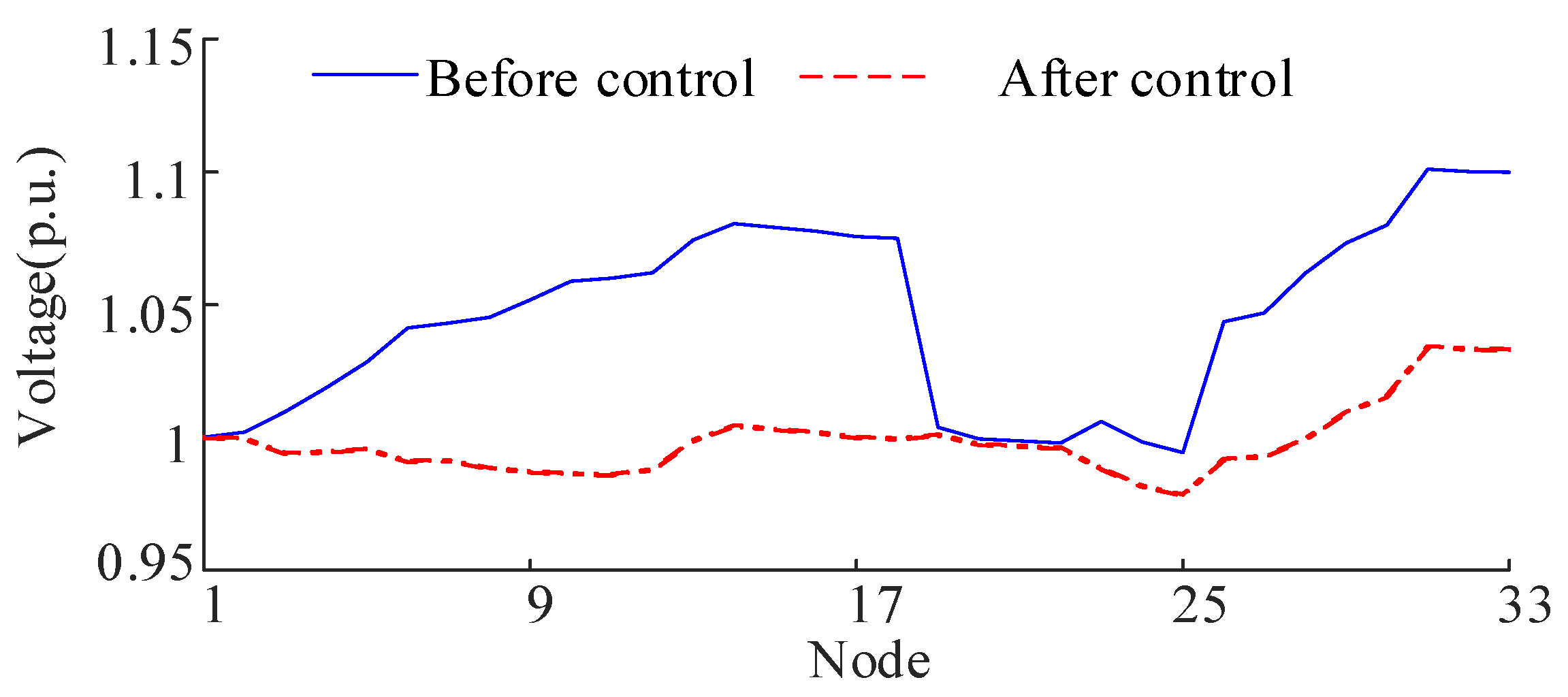
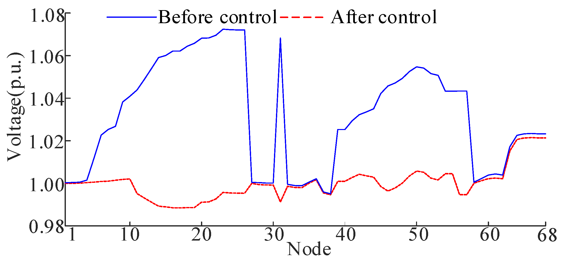
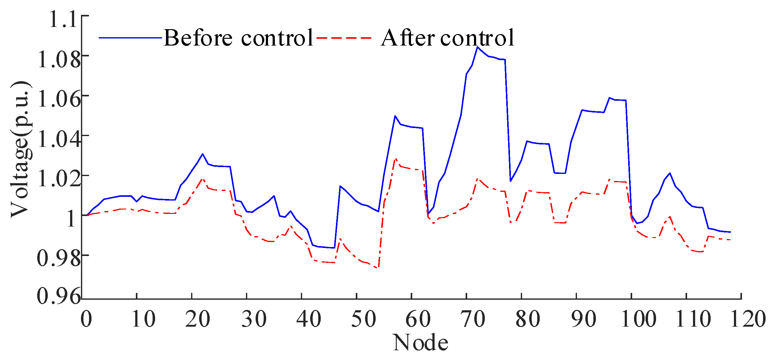
Table 1.
ESS control gains.
Figure 4 compares node voltage profiles in the IEEE 33-node system before and after control implementation, while Table 2 summarizes the corresponding ESS power rates after control implementation. Prior to control, the maximum voltage deviation reaches 0.0847 p.u. Post-control measurements confirm all voltages stabilize within the prescribed 0.95–1.05 p.u. range. Table 2 reveals balanced ESS power rates across units, exhibiting a maximum power rate difference of merely 0.0788. These findings demonstrate the controller’s dual capability: maintaining nodal voltages within safe operational limits while achieving ESS load equilibrium.
Figure 4.
Nodal voltage of IEEE33 before and after control.
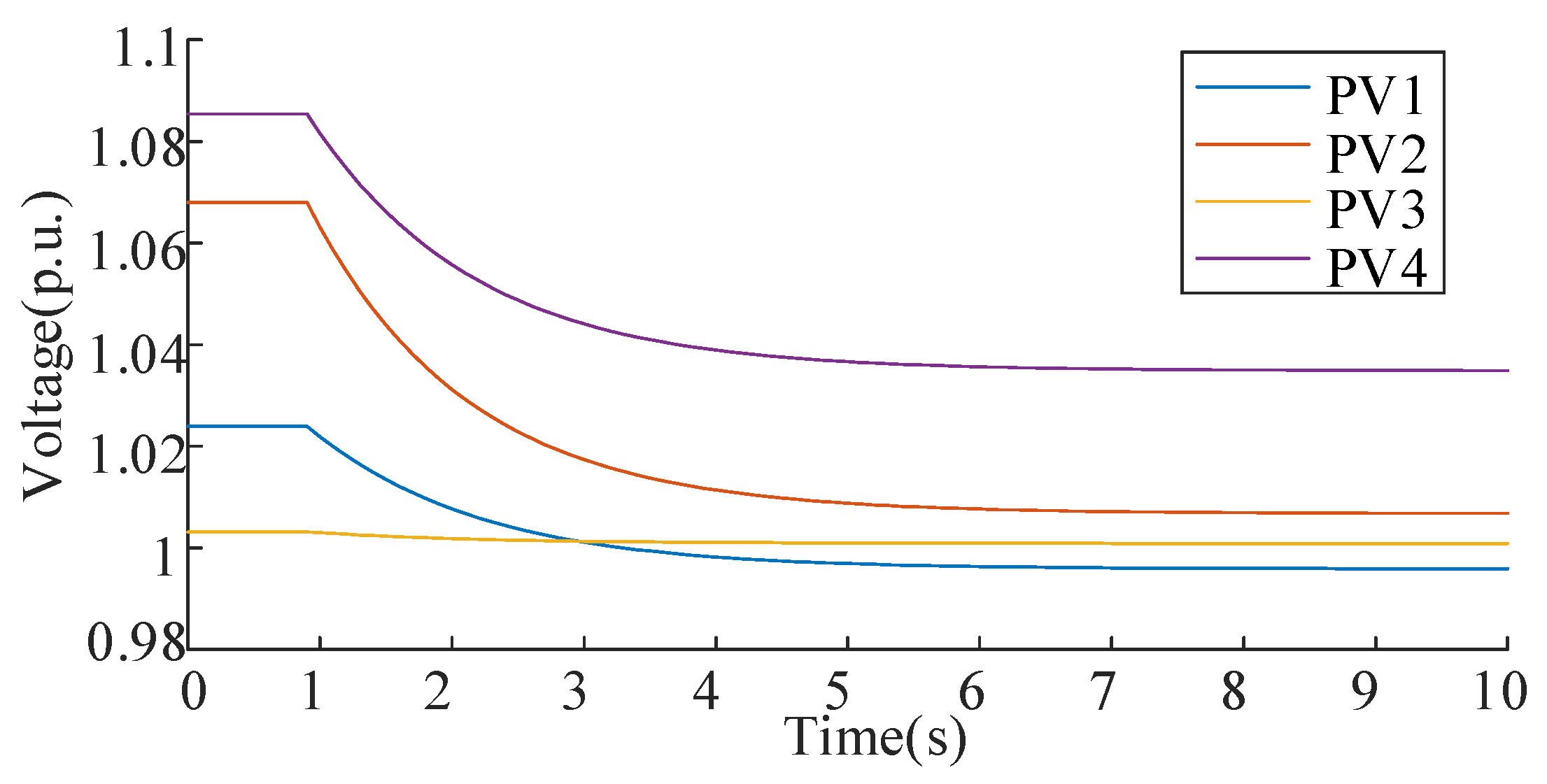
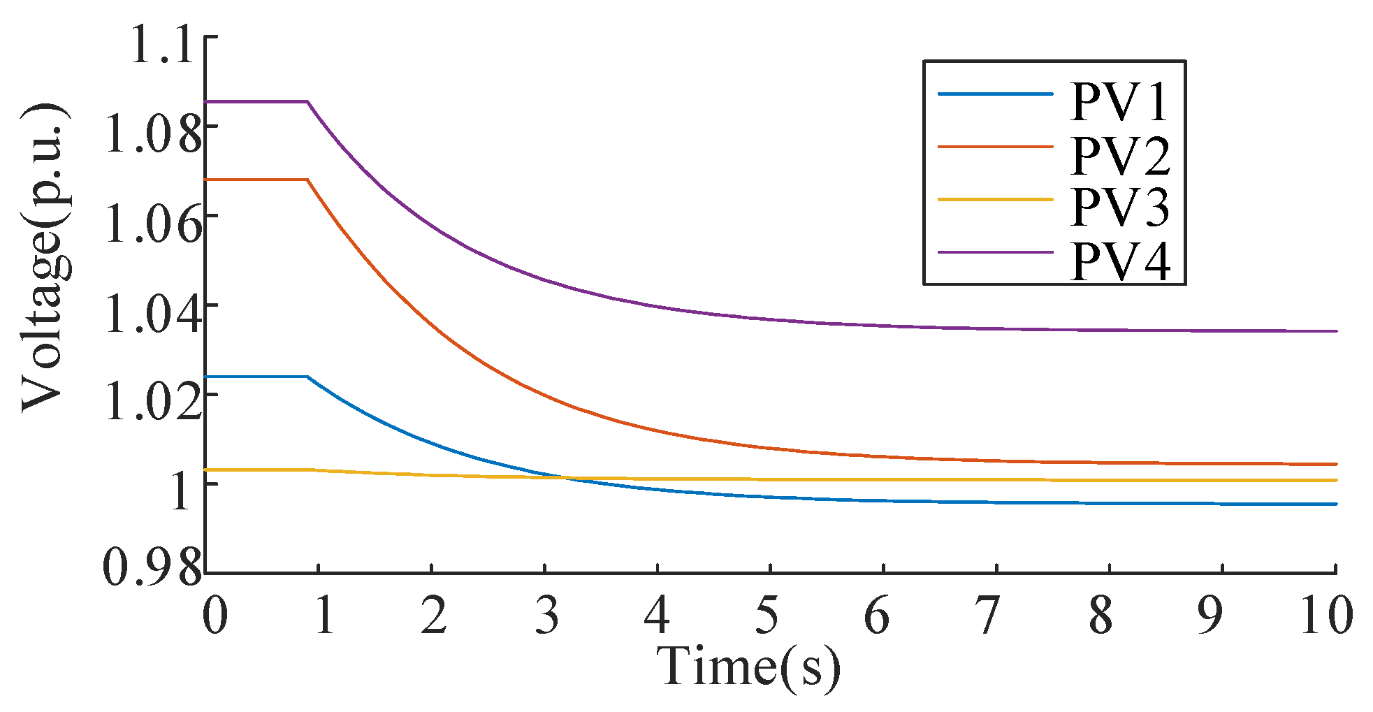
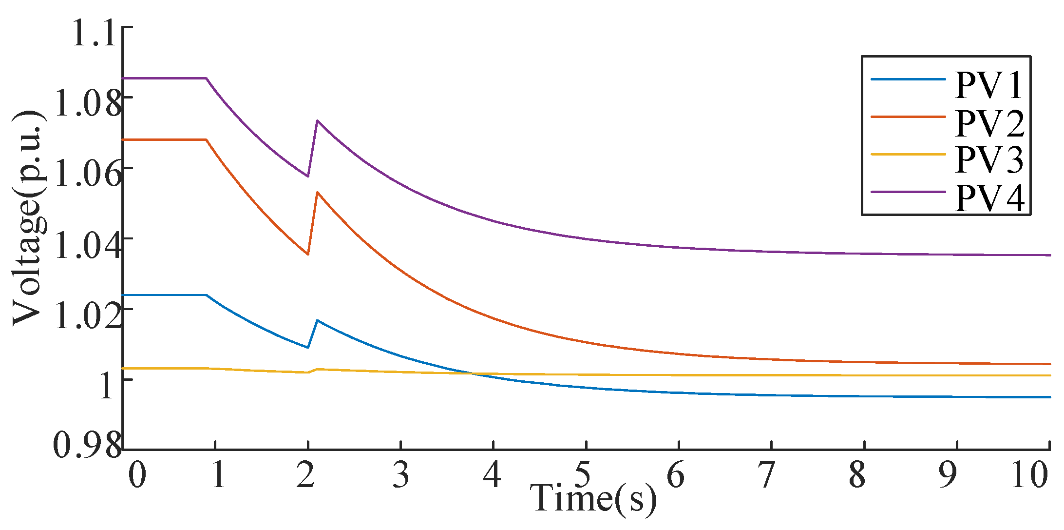
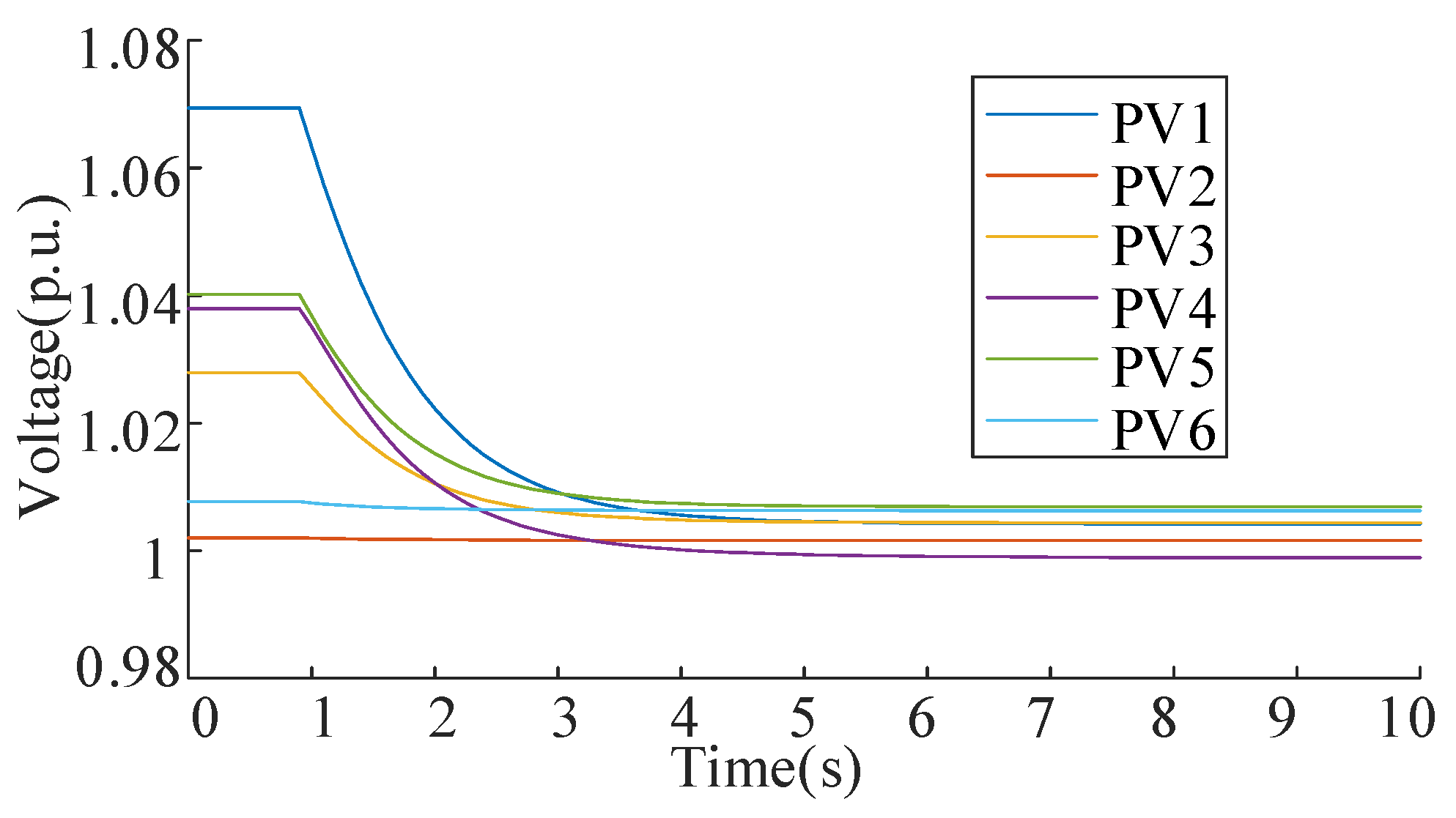
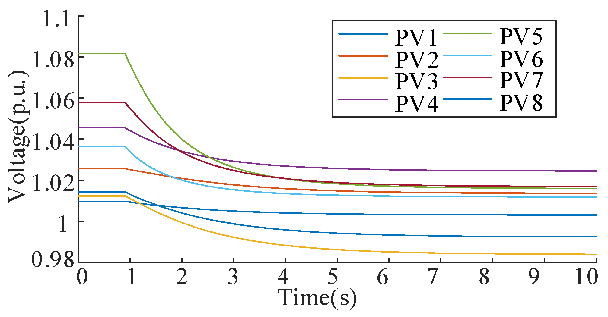
Table 2.
ESS power rates after control.
Nodal voltage variations at PV buses during the control process are demonstrated in Figure 5. Before activation, bus voltages at PV 1 and PV 2 exceed the permissible range of 0.95 to 1.05 p.u. After regulation, all PV voltages stabilize within the required operational limits, confirming the controller’s performance. Figure 6 illustrates the coordinated ESS operation. The charging powers are 0.9280 MW, 0.9879 MW, 1.0226 MW, and 0.9973 MW for ESS1~ESS4. Figure 7 tracks system convergence dynamics. The convergence criteria are satisfied at 6.0 s. This corresponds to 50 iterative computational cycles, demonstrating the algorithm’s rapid response capability in real-time regulation scenarios.
Figure 5.
Nodal voltage variation at PV buses of IEEE33 during the control process.
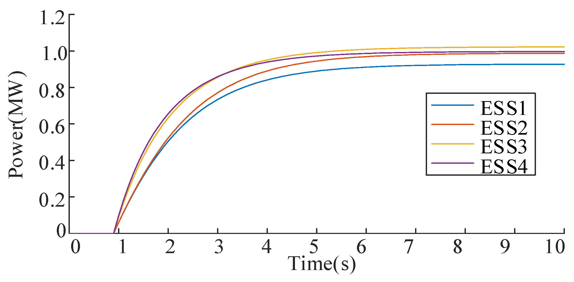
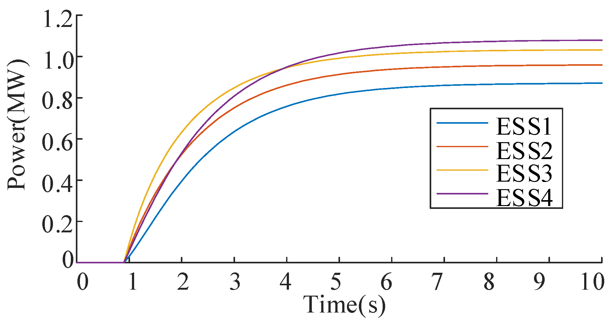
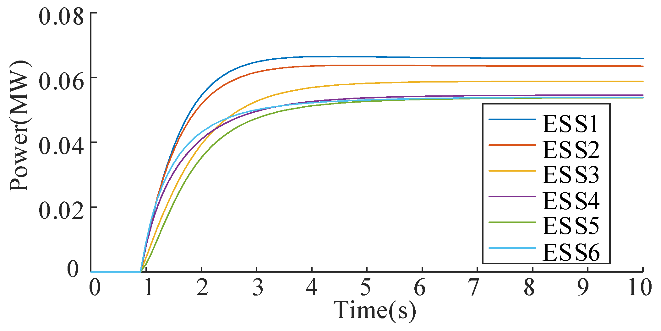
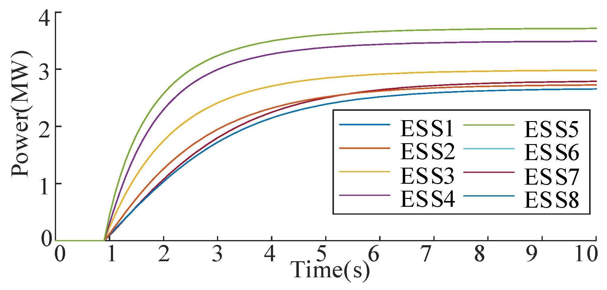
Figure 6.
ESS output powers of IEEE33 bus system during the control process.
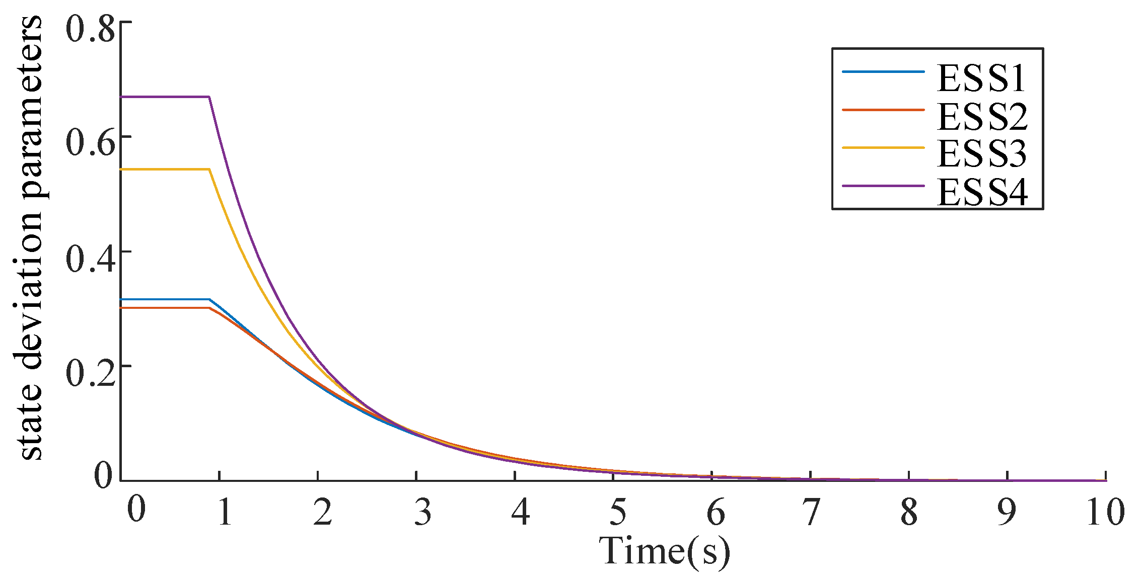
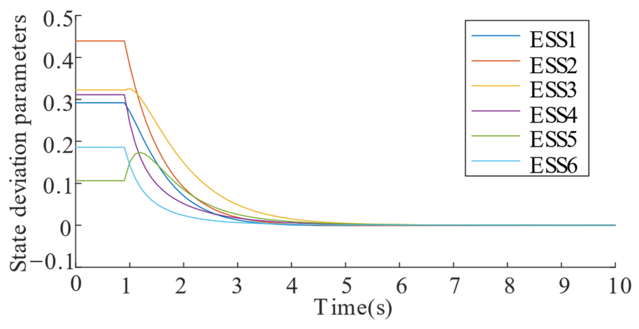
Figure 7.
ESS state deviation parameters of IEEE33 during the control process.
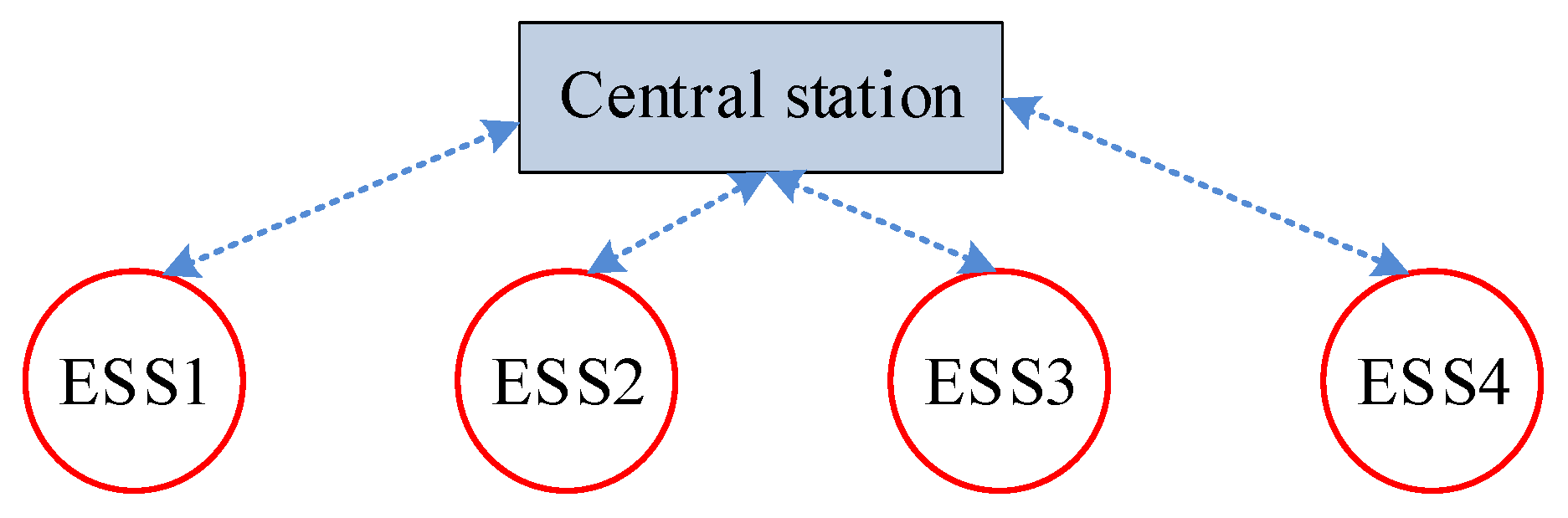
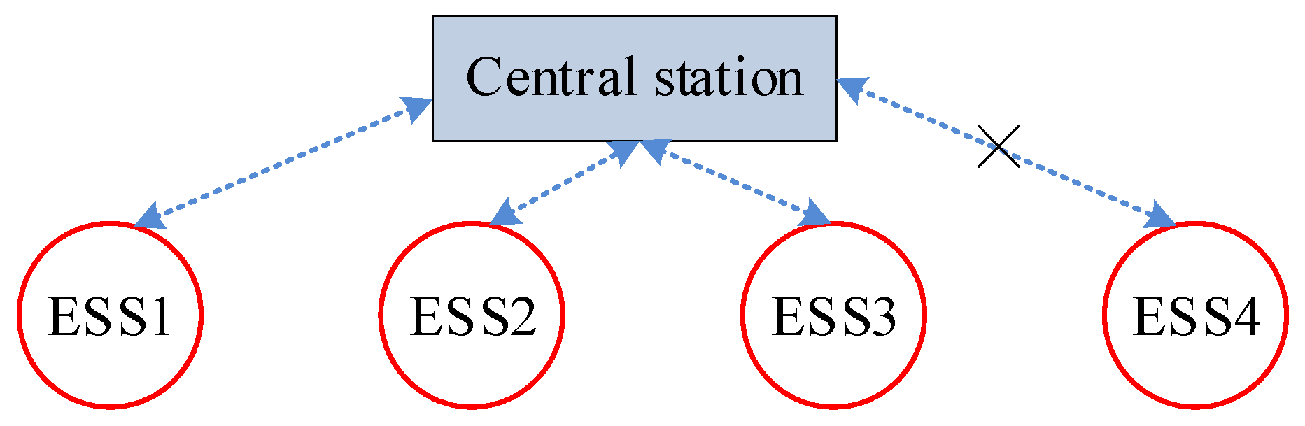
6.2. Comparison with the Centralized Method
To evaluate the proposed distributed controller’s efficacy, comparative simulations are conducted against a conventional centralized controller based on linear quadratic optimal control [23]. The communication framework under centralized control is shown in Figure 8.
Figure 8.
Communication framework under centralized control.
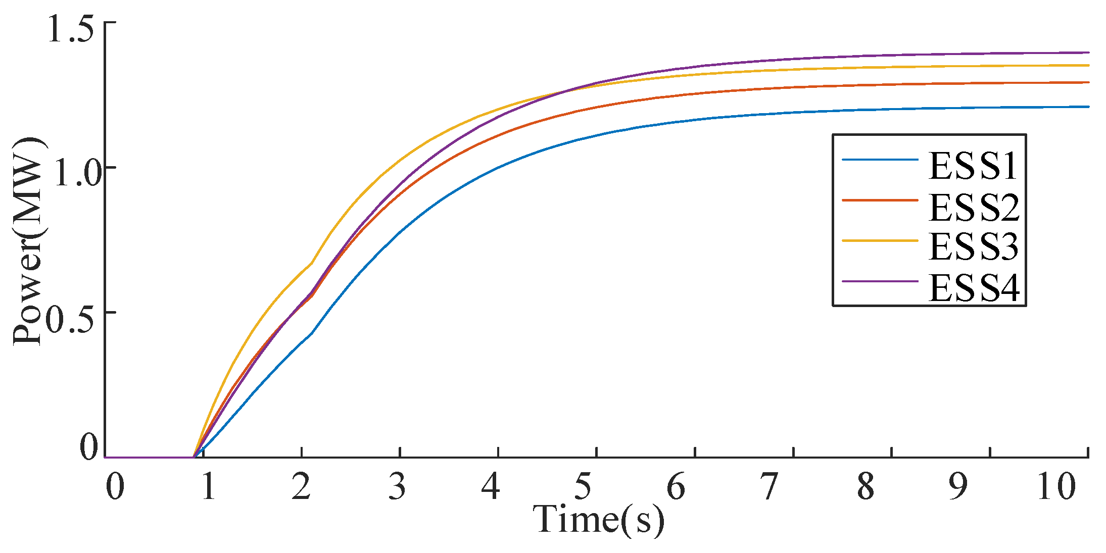
Figure 9 displays the ESS charging power profiles under both control architectures. Notably, both methods produce identical ESS charging power trajectories, confirming equivalent electrical performance. This equivalence demonstrates the distributed controller’s capability to match centralized control precision while implementing critical architectural improvement: replacing global communication with localized inter-cluster data exchange. The distributed approach reduces communication complexity compared to the centralized paradigm while maintaining equivalent dynamic response characteristics.
Figure 9.
The charging power of ESS under distributed control and centralized control.
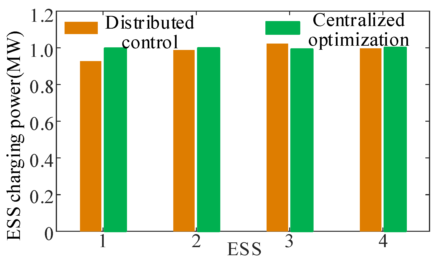
For the original problem defined in Equations (8) and (9), we utilize the interior point method [24] as the centralized optimization approach to obtain the optimal solution, employing an accurate power flow model for nodal voltage calculations. Figure 10 compares ESS charging power profiles under distributed control and centralized optimization, while Figure 11 presents the corresponding nodal voltages. The results demonstrate that the nodal voltages achieved by both methods are remarkably close, with a maximum voltage magnitude difference of only 0.0022 p.u. observed between them. Regarding control speed, the centralized optimization converges to its optimal solution within 6 s. Notably, no ESS power adjustments occur prior to the output of this optimal solution. In contrast, distributed control employs a feedback mechanism for real-time voltage regulation, completing this control process within 5 s. Therefore, the proposed distributed control enables rapid voltage recovery through real-time feedback, achieving a faster response compared to centralized optimization.
Figure 10.
The charging power of ESS under distributed control and centralized optimization.
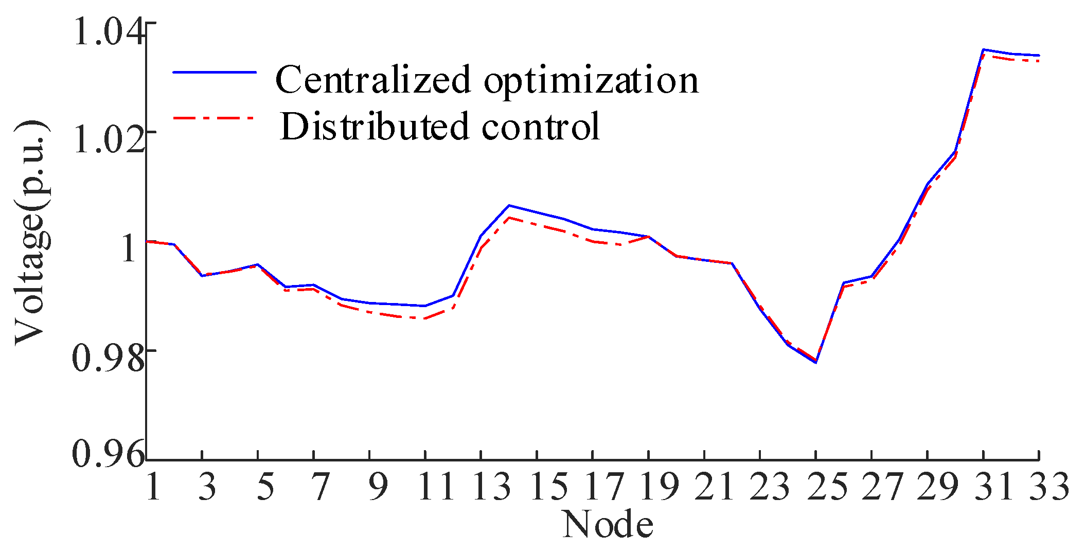
Figure 11.
Nodal voltage of IEEE33 under distributed control and centralized optimization.
6.3. Comparison with Other Distributed Methods
To evaluate the stability and convergence speed of the proposed distributed controller, we compare its performance with the subgradient method-based distributed control approach described in Reference [25]. The gradient values D for each ESS are 17.30, 18.24, 19.78, and 21.63. Representative simulation results for the subgradient method under varying step sizes (from 0.1 to 0.001) are presented in Table 3. The results demonstrate that the step size significantly impacts convergence speed within the subgradient method: larger step sizes accelerate convergence but risk instability if excessive, while smaller step sizes ensure stability at the cost of slower response to voltage fluctuations. In contrast, the proposed method provides a systematic approach for determining the control gain, ensuring both rapid convergence and stable operation.
Table 3.
Convergence speed of the gradient method under different step sizes.
6.4. Controller Robustness Analysis Against Line Impedance Variation
During the operation of power distribution networks, line impedance parameters may vary due to environmental factors. To evaluate the adaptability of the designed controller to impedance variations, the line impedance is increased to 1.2 times its initial value for robustness analysis.
Figure 12 demonstrates voltage variations in the IEEE 33-node system before and after control implementation. Initially, the system exhibited a maximum voltage deviation of 0.1010 p.u. Following control activation, all voltages stabilized within the 0.95–1.05 p.u. operational standard. Table 4 shows balanced power distribution among ESS units, with the largest power rate variation limited to 0.2057 between units. These findings demonstrate the controller’s robustness to fit the line impedance.
Figure 12.
Nodal voltage before and after control in the case considering line impedance variation.
Table 4.
ESS power rates after control in the case considering line impedance variation.
6.5. Controller Robustness Analysis Against Communication Failures
To ensure the reliability of the proposed distributed control methodology, partial communication failure constitutes a critical practical concern that warrants thorough investigation. To systematically examine this scenario, we assume a permanent communication failure occurs between ESS1 and ESS4, shown in Figure 13. Consequently, ESS1 and ESS4 can no longer exchange information with each other.
Figure 13.
Diagram of communication failure in distributed control.
The PV voltages and the ESS discharging power under communication failure are shown in Figure 14 and Figure 15, respectively. The PV voltages and ESS power rate comparisons are shown in Table 5 and Table 6, respectively. Compared with normal communication, the maximum voltage deviation under communication failure increases from 0. 0418 p.u. to 0. 0356 p.u., and the maximum ESS power ratio deviation increases from 0.0788 p.u. to 0.0939 p.u. However, the convergence criteria are satisfied at 7.0 s; this corresponds to 70 iterative computational cycles. The controller is still stable under the partial communication failure. The simulation results show that although the steady performance is influenced by partial communication failures, the proposed distributed control strategy can still achieve voltage recovery and ESS power balance.
Figure 14.
Nodal voltage variation at PV buses under communication failure.
Figure 15.
ESS discharging powers under communication failure.
Table 5.
PV voltage comparisons.
Table 6.
ESS power rate comparisons.
To enable comparative analysis, centralized control performance under communication failure is evaluated. Similar to the distributed control scenario, a communication failure occurs between ESS4 and the central station (Figure 16). Voltage profiles of PV systems and ESS power rates under this failure are compared in Table 7 and Table 8, respectively. Due to the communication failure, the central station loses connectivity with ESS4. Consequently, ESS1–ESS3 can only operate using local information from ESS1–ESS3. This limitation causes the nodal voltage at PV4 to exceed the allowable range. Based on the results presented in Table 6 and Table 7, the distributed control demonstrates superior resilience compared to centralized control. Even with a communication line failure, the distributed control maintains effective regulation and prevents PV bus voltages from exceeding operational limits.
Figure 16.
Diagram of communication failure in centralized control.
Table 7.
PV voltage comparisons under communication failure.
Table 8.
ESS power rate comparisons under communication failure.
6.6. Analysis of Implementation Costs
This section evaluates the implementation costs associated with voltage recovery through three comparative cases. Case 1 through Case 3 employ weight coefficients c of 0, 1, and 3, respectively. The resulting PV voltage profiles and ESS power ratios are compared in Table 9 and Table 10. Total ESS discharge power losses measure 283.08 kW, 281.01 kW, and 272.75 kW for Cases 1–3, demonstrating a reduction in power loss with increasing c. Conversely, the maximum ESS power ratio differential widens as c increases, while PV voltages remain relatively unaffected by coefficient variations. These results confirm that adjusting weight coefficient c enables the proposed control method to balance implementation cost reduction with ESS power ratio optimization.
Table 9.
PV voltage comparisons under different weight coefficients.
Table 10.
ESS power rate comparisons under different weight coefficients.
6.7. Tests in Disturbance Conditions
The control performance of the proposed controller is further validated under dynamic power variations. We design a test scenario featuring simultaneous 50% reductions in load power and PV output power at t = 3.0 s. Corresponding PV voltages and ESS power responses are shown in Figure 17 and Figure 18, respectively. A voltage rise occurs immediately at t = 3.0 s due to the load power reduction. Under controller action, voltages gradually converge toward nominal values, achieving convergence criteria at t = 7.0 s with a maximum observed deviation of 0.0352 p.u. These results demonstrate the controller’s capability to effectively regulate voltage during transient conditions, maintaining stability despite abrupt generation-load imbalances.
Figure 17.
Nodal voltage variation at PV buses of IEEE33 in disturbance conditions.
Figure 18.
ESS output powers of IEEE33 bus system in disturbance conditions.
6.8. Test System 2
The proposed methodology is further validated through comprehensive simulations conducted on the IEEE69-bus test feeder. Six ESSs are strategically deployed at buses 8, 12, 20, 29, 47, and 63, with each unit configured for a rated output power of 1.2 MW. PV integration is implemented at buses 24, 37, 43, 51, 55, and 67, featuring respective rated capacities of 0.75 MVA, 1.5 MVA, 0.75 MVA, 2.0 MVA, 1.0 MVA, and 1.0 MVA.
Figure 19 illustrates the system topology and the corresponding cluster division results of the IEEE69 bus system. The objective function employs weighting coefficients α = 10 and β = 1. The control gains for each ESS are shown in Table 11.
Figure 19.
Cluster division results of IEEE69 bus system.
Table 11.
ESS control gains in IEEE69 bus system.
Figure 20 shows voltage distributions across the network before and after control implementation. Before control, peak voltages reached 1.0718 p.u., exceeding safe limits. The proposed voltage control strategy successfully maintains all node voltages within the 0.95–1.05 p.u. operational range. Table 12 confirms precise power sharing between ESS units, with power sharing differences below 0.0168 p.u. These results demonstrate the controller’s dual capability: securing grid voltage stability while ensuring fair energy distribution among ESS units.
Figure 20.
Nodal voltage of IEEE69 before and after control.
Table 12.
ESS load rates after control.
Figure 21 demonstrates the nodal voltage variation at PV buses during the control process. Before activation, bus voltage at PV 1 exceeds the permissible range of 0.95 to 1.05 p.u. After regulation, all nodal voltages stabilize within the required operational limits, confirming the controller’s performance. Figure 22 illustrates the coordinated ESS operation. The charging powers are 0.6593 MW, 0.6350 MW, 0.5884 MW, 0.5458 MW, 0.5377 MW, and 0.5394 MW for ESS1~ESS6. Figure 23 tracks system convergence dynamics. Nodal voltages reach the convergence within 6 s. This corresponds to 60 iterative computational cycles, demonstrating the algorithm’s rapid response capability in real-time regulation scenarios.
Figure 21.
Nodal voltage variation of IEEE69 bus system during the control process.
Figure 22.
ESS discharging powers of IEEE69 bus system during the control process.
Figure 23.
ESS state deviation parameters of IEEE69 during the control process.
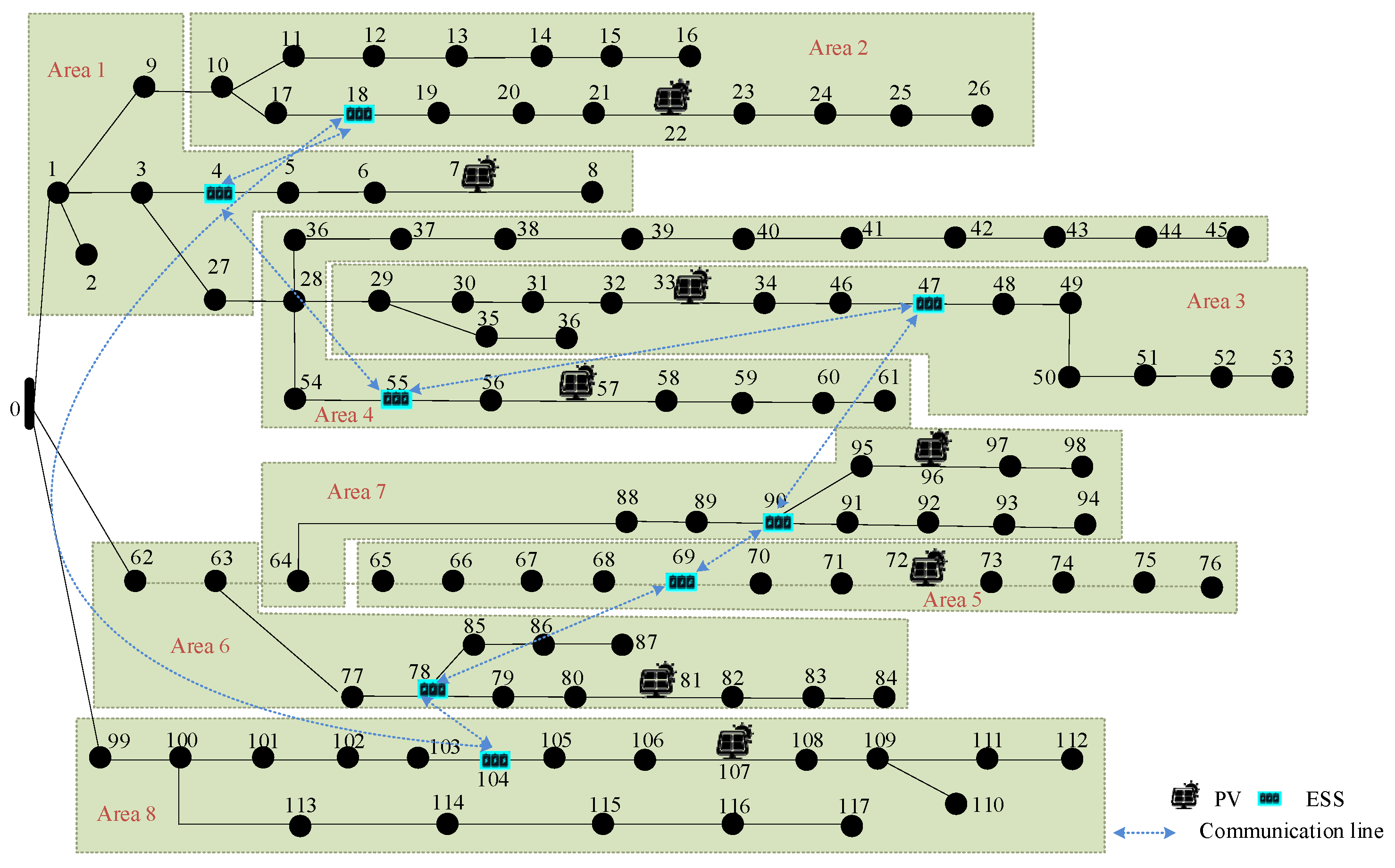
6.9. Test System 3
The proposed methodology is further validated on the IEEE118 bus system [26]. Eight ESSs are strategically deployed at buses 4, 18, 47, 55, 69, 78, 90, and 104, with each unit configured for a rated output power of 1.2 MW. PV integration is implemented at buses 7, 22, 33, 57, 81, 96, and 107, featuring respective rated capacities of 7 MVA. Figure 24 illustrates the system topology and the corresponding cluster division results of the IEEE118 bus system.
Figure 24.
Cluster division results of IEEE118 bus system.
Figure 25 shows voltage distributions across the network before and after control implementation. Before control, peak voltages reached 1.0843 p.u., exceeding safe limits. The proposed voltage control strategy successfully maintains all node voltages within the 0.95–1.05 p.u. operational range. Figure 26 illustrates the coordinated ESS operation. The charging powers are 0.2793 MW, 0.2660 MW, 0.2729 MW, 0.2984 MW, 0.3489 MW, 0.3717 MW, 0.3345 MW, and 0.3023 MW for ESS1~ESS8. Figure 27 demonstrates the nodal voltage variation at PV buses during the control process. Before activation, bus voltage at PV 1 exceeds the permissible range of 0.95 to 1.05 p.u. After regulation, all PV voltages stabilize within the required operational limits, confirming the controller’s performance. Nodal voltages reach the convergence within 8 s. This corresponds to 80 iterative computational cycles, demonstrating the algorithm’s rapid response capability in real-time regulation scenarios.
Figure 25.
Nodal voltage of IEEE118 before and after control.
Figure 26.
ESS discharging powers of IEEE118 bus system during the control process.
Figure 27.
Nodal voltage variation of IEEE118 bus system during the control process.
7. Conclusions
This paper proposes a distributed multi-objective control method for ESSs. The conclusions are drawn below:
- (i)
- The proposed distributed control method can achieve voltage recovery and ESS power balance only by peer-to-peer communication. The communication burdens of the proposed distributed control method are much less than those of centralized approaches.
- (ii)
- The proposed feedback-control-gains optimization method can not only ensure system stability but also improve the convergence rate.
In future work, the proposed distributed approach will be validated in practical systems considering communication delay and measurement error.
Author Contributions
Methodology, Y.L.; Software, W.L.; Validation, Y.W.; Formal analysis, Y.L.; Investigation, H.Y.; Resources, W.L.; Writing—original draft, W.L.; Project administration, Y.L. All authors have read and agreed to the published version of the manuscript.
Funding
This work was funded by the State Grid Shandong Electric Power Company. Project Name: “Cloud-Edge Collaboration” Regulation Technology for Novel Distribution Systems Aimed at Enhancing Risk Prevention and Control Capabilities. Grant number: 520626240005.
Data Availability Statement
The data presented in this study are available on request from the corresponding author (The data are not publicly available due to privacy restrictions).
Conflicts of Interest
Authors Yang Liu, Wenbin Liu, Ying Wu, and Haidong Yu were employed by the State Grid Shandong Electric Power Research Institute. The remaining authors declare that the research was conducted in the absence of any commercial or financial relationships that could be construed as a potential conflict of interest.
References
- Wang, P.; Liang, F.; Song, J.; Jiang, N.; Zhang, X.P.; Guo, L.; Gu, X. Impact of the PV location in distribution networks on network power losses and voltage fluctuations with PSO analysis. CSEE J. Power Energy Syst. 2022, 8, 523–534. [Google Scholar]
- Deng, X.; Lv, T. Power system planning with increasing variable renewable energy: A review of optimization models. J. Clean. Prod. 2020, 246, 118962. [Google Scholar] [CrossRef]
- Si, Z.; Yang, M.; Yu, Y.; Ding, T. Photovoltaic power forecast based on satellite images considering effects of solar position. Appl. Energy 2021, 302, 117514. [Google Scholar] [CrossRef]
- Joseph, A.; Smedley, K.; Mehraeen, S. Secure High DER penetration power distribution via autonomously coordinated volt/VAR control. IEEE Trans. Power Deliv. 2020, 35, 2272–2284. [Google Scholar] [CrossRef]
- Zhang, Z.; Dou, C.; Yue, D. Event-triggered voltage regulation for high-PV-penetration networks with time delays. IEEE Trans. Ind. Inform. 2024, 20, 5581–5591. [Google Scholar] [CrossRef]
- Li, Z.; Wu, L.; Xu, Y. Risk-averse coordinated operation of a multi-energy microgrid considering voltage/var control and thermal flow: An adaptive stochastic approach. IEEE Trans. Smart Grid 2021, 12, 3914–3927. [Google Scholar] [CrossRef]
- Tewari, T.; Mohapatra, A.; Anand, S. Coordinated control of OLTC and energy storage for voltage regulation in distribution network with high PV penetration. IEEE Trans. Sustain. Energy 2021, 12, 262–272. [Google Scholar] [CrossRef]
- Satea, M.; Elsadd, M.; Zaky, M.; Elgamasy, M. Reliable high impedance fault detection with experimental investigation in distribution systems. Eng. Technol. Appl. Sci. Res. 2024, 14, 17248–17255. [Google Scholar] [CrossRef]
- Elgamasy, M.M.; Elezzawy, A.I.; Kawady, T.A.; Elkalashy, N.I.; Elsadd, M.A. Tracing passive traveling surge-based fault management control scheme in unearthed distribution systems. Electr. Eng. 2024, 106, 5603–5624. [Google Scholar] [CrossRef]
- Zhang, L.; Shen, C.; Chen, Y.; Huang, S.; Tang, W. Coordinated allocation of distributed generation, capacitor banks and soft open points in active distribution networks considering dispatching results. Appl. Energy 2018, 231, 1122–1131. [Google Scholar] [CrossRef]
- Li, P.; Ji, H.; Wang, C.; Zhao, J.; Song, G.; Ding, F.; Wu, J. Coordinated control method of voltage and reactive power for active distribution networks based on soft open point. IEEE Trans. Sustain. Energy 2017, 8, 1430–1442. [Google Scholar] [CrossRef]
- Sun, X.; Zhang, W.; Chen, J. Optimize globally, control locally: Coordinated optimal local voltage control in hybrid AC/DC microgrid. Int. J. Electr. Power Energy Syst. 2020, 118, 105734. [Google Scholar] [CrossRef]
- Li, P.; Ji, H.; Song, G.; Yao, M.; Wang, C.; Wu, J. A combined central and local voltage control strategy of soft open points in active distribution networks. Energy Procedia 2019, 158, 2524–2529. [Google Scholar] [CrossRef]
- Ortmann, L.; Prostejovsky, A.; Heussen, K.; Bolognani, S. Fully distributed peer-to-peer optimal voltage control with minimal model requirements. Electr. Power Syst. Res. 2020, 189, 106717. [Google Scholar] [CrossRef]
- Olivier, F.; Aristidou, P.; Ernst, D.; Cutsem, T.V. Active management of low-voltage networks for mitigating overvoltages due to photovoltaic units. IEEE Trans. Smart Grid 2016, 7, 926–936. [Google Scholar] [CrossRef]
- Kang, W.; Chen, M.; Lai, W.; Luo, Y. Distributed real-time power management of high-penetrated PV sources with voltage regulation over time-varying networks. Int. J. Electr. Power Energy Syst. 2021, 129, 106720. [Google Scholar] [CrossRef]
- Derakhshan, S.; Shafiee-Rad, M.; Shafiee, Q.; Jahed-Motlagh, M.R. Decentralized robust LMI-Based voltage control strategy for autonomous inverter-interfaced multi-DG Microgrids. IEEE Trans. Power Syst. 2023, 38, 3003–3015. [Google Scholar] [CrossRef]
- Lou, G.; Gu, W.; Wang, J.; Sheng, W.; Sun, L. Optimal design for distributed secondary voltage control in islanded microgrids: Communication topology and controller. IEEE Trans. Power Syst. 2019, 34, 968–981. [Google Scholar] [CrossRef]
- Liu, Q.; Zhang, L.; Zhang, H.; Wang, S.; Ji, X. Distributed secondary optimal control with fast voltage recovery and minimum generation cost for islanded DC microgrids. IEEE Trans. Smart Grid 2025, 16, 4–15. [Google Scholar] [CrossRef]
- Wang, S.; Liu, Q.; Ji, X. A fast sensitivity method for determining line loss and node voltages in active distribution network. IEEE Trans. Power Syst. 2018, 33, 1148–1150. [Google Scholar] [CrossRef]
- Newman, M.E.J. Fast algorithm for detecting community structure in networks. Phys. Rev. E 2004, 69, 066133. [Google Scholar] [CrossRef]
- Yang, S.; Tan, S.; Xu, J.-X. Consensus based approach for economic dispatch problem in a smart grid. IEEE Trans. Power Syst. 2013, 28, 4416–4426. [Google Scholar] [CrossRef]
- Jing, Z.; Gao, L.; Wu, C.; Liang, D. Linear quadratic regulator-based coordinated voltage and power control for flexible distribution networks. Energies 2025, 18, 361. [Google Scholar] [CrossRef]
- Nocedal, J.; Öztoprak, F.; Waltz, R.A. An interior point method for nonlinear programming with infeasibility detection capabilities. Optim. Methods Softw. 2014, 29, 837–854. [Google Scholar] [CrossRef]
- Wang, Z.; Wu, W.; Zhang, B. A distributed control method with minimum generation cost for DC microgrids. IEEE Trans. Energy Convers. 2016, 31, 1462–1470. [Google Scholar] [CrossRef]
- Liu, Q.; Ji, X.; Wang, H. Dynamic reconfiguration of active distribution system based on matrix shifting operation and interval merger. J. Electr. Eng. Technol. 2020, 15, 621–633. [Google Scholar] [CrossRef]
Disclaimer/Publisher’s Note: The statements, opinions and data contained in all publications are solely those of the individual author(s) and contributor(s) and not of MDPI and/or the editor(s). MDPI and/or the editor(s) disclaim responsibility for any injury to people or property resulting from any ideas, methods, instructions or products referred to in the content. |
© 2025 by the authors. Licensee MDPI, Basel, Switzerland. This article is an open access article distributed under the terms and conditions of the Creative Commons Attribution (CC BY) license (https://creativecommons.org/licenses/by/4.0/).