Article

Fluid Dynamics Analysis of Flow Characteristics in the Clearance of Hydraulic Turbine Seal Rings

1
Hubei Technology Innovation Center for Smart Hydropower, Wuhan 430000, China
2
China Yangtze Power Co., Ltd., Yichang 443002, China
3
College of Water Conservancy and Construction Engineering, Northwest A&F University, Yangling 712100, China
*
Author to whom correspondence should be addressed.
Energies 2025, 18(14), 3726; https://doi.org/10.3390/en18143726
Submission received: 29 May 2025 / Revised: 6 July 2025 / Accepted: 11 July 2025 / Published: 14 July 2025
(This article belongs to the Special Issue Optimization Design and Simulation Analysis of Hydraulic Turbine)

Abstract

The hydraulic turbine serves as the cornerstone of hydropower generation systems, with the sealing system’s performance critically influencing energy conversion efficiency and operational cost-effectiveness. The sealing ring is a pivotal component, which mitigates leakage and energy loss by regulating flow within the narrow gap between itself and the frame. This study investigates the intricate flow dynamics within the gap between the sealing ring and the upper frame of a super-large-scale Francis turbine, with a specific focus on the rotating wall’s impact on the flow field. Employing theoretical modeling and three-dimensional transient computational fluid dynamics (CFD) simulations grounded in real turbine design parameters, the research reveals that the rotating wall significantly alters shear flow and vortex formation within the gap. Tangential velocity exhibits a nonlinear profile, accompanied by heightened turbulence intensity near the wall. The short flow channel height markedly shapes flow evolution, driving the axial velocity profile away from a conventional parabolic pattern. Further analysis of rotation-induced vortices and flow instabilities, supported by turbulence kinetic energy monitoring and spectral analysis, reveals the periodic nature of vortex shedding and pressure fluctuations. These findings elucidate the internal flow mechanisms of the sealing ring, offering a theoretical framework for analyzing flow in microscale gaps. Moreover, the resulting flow field data establishes a robust foundation for future studies on upper crown gap flow stability and sealing ring dynamics.

1. Introduction

As the core power-conversion device in modern hydropower systems, the investigation of the internal fluid characteristics of hydraulic turbines has been a long-standing research topic [1]. A turbine’s fluid-dynamic performance directly determines both its energy-conversion efficiency and the levelized cost of electricity over the plant’s entire life cycle. According to the IEA’s World Energy Outlook 2022, hydropower accounts for 61.8% of global renewable-generation capacity [2], a leading position derived from its superior conversion efficiency, operational flexibility, and large-scale storage capability. However, as individual unit capacities exceed the megawatt scale and design heads extend to around 800 m, transient hydraulic excitations within the system have increasingly manifested, making the safe and stable operation of the units paramount.
Seal rings are critical sealing components in rotating machinery: the narrow annular gap between the ring and the upper bracket plays an indispensable role in maintaining turbine efficiency and stability. Research has shown that even a small gap at this location can lead to efficiency loss, and the degree of loss increases with the gap size. The loss is particularly severe when there are sediments in the water [3]. The presence of the sealing ring significantly affects pressure fluctuations in the gap flow and alters the axial hydraulic thrust during the hydraulic transient process [4].
In super-large-scale Francis turbines, although the clearance is very small and the fluid volume in these regions is several orders of magnitude smaller compared to other dimensions in the hydraulic turbine, the flow characteristics in these areas can have a significant impact on the overall flow within the machine. Studies have found that the leakage flow in the sidewall gap contributes significantly to the fluid-induced rotor dynamics forces. Swiss scholar Peter Dorfler et al. [5] highlighted the effects of gap flow in the sealing ring, noting that the gap flow phenomenon has an important interference effect on the rotational motion between the rotor and the stationary components, thereby influencing the pressure distribution in the sealing gap. The resulting hydraulic reaction forces form a feedback mechanism on the rotor. This transient hydraulic excitation phenomenon is particularly pronounced under variable-speed operating conditions, where nonlinear flow effects within micro-gaps of 0.5–5 mm can amplify pressure pulsations to two to three times those of steady-state conditions [6]. Such transient hydraulic excitations are particularly pronounced under variable-speed operation.
The flow through the seal-ring gap is characterized by strong multi-physics coupling: first, seal rings are interference-fitted via a thermal expansion process, imparting a preload; second, the combined effects of cavitation and abrasion in sediment-laden water shorten sealing life; and third, the rotational effects of the runner crown introduce positional sensitivity in pressure pulsations, further increasing the risk during normal operation.
The flow within the sidewall gap is highly complex and can exhibit various states and structures. The labyrinth seal consists of a series of narrow annular gaps and chambers between the rotating and stationary components. The flow within these regions is typically turbulent. Flow characteristics in this region not only govern leakage control but also directly influence the uniformity of pressure distribution and the degree of energy loss. Existing studies indicate that in rotating gap cavities, high-speed fluid motion induces significant hydrodynamic pressure effects, thereby enhancing film lift and stiffness. For example, in the downstream cavity of a supercritical CO2 compressor impeller and in seal-ring chambers, researchers have observed the formation of enlarged high-vorticity regions as rotational speed and pressure ratio increase—an outcome of intensified flow instability. The expansion of these high-vorticity zones demonstrates that high-speed rotation in small gaps generates strong vortex structures and markedly increases the friction-resistance coefficient [7]. Overall, rotating small-gap flows are typically accompanied by complex tangential convergence and vortex structures, with flow-field features that differ markedly from those under stationary conditions.
In rotating shear flows, boundary-layer instabilities are key to flow evolution. Cui et al. [8] point out in their review that in thin oil films between multiple rotating disks, the interplay of squeeze and shear effects renders the laminar-to-turbulent transition exceedingly complex. Du et al. [9] further demonstrate that in rotating-stationary disk cavities, turbulence tends to first emerge in the stationary disk’s boundary layer. As the Reynolds number rises, spiral-instability modes amplify and interact with axisymmetric wave modes, leading to localized turbulence. These findings highlight that three-dimensional vortex structures—such as spiral waves—dominate the unsteady evolution of rotating cavity flows and are crucial to understanding turbulence onset and instability mechanisms.
Numerous researchers and academic authorities have formulated theoretical models and solved analytical equations for the flow in such regions. We consider the coaxial cylindrical gap flow with the inner cylinder rotating and the outer cylinder fixed, while superimposing axial flow driven by an axial pressure gradient. This basic flow is steady and laminar and can be decomposed into a radial no-flow, circumferential Couette component, and an axial Poiseuille component. Starting from the incompressible Navier–Stokes equations and assuming axial and circumferential translation invariance, the benchmark equation for no radial flow can be solved to obtain the laminar velocity analytical expression. Martinand et al. [10] provided the benchmark flow analytical expression for the ratio of the inner and outer cylinder radii. In the case of a narrow gap, the Taylor–Couette system can be approximated as a parallel plate model. Recently, Nagata et al. [11] performed a theoretical analysis of this limit by applying Cartesian coordinate processing in the slit limit. A linear stability analysis of the region was also conducted based on the benchmark laminar flow. It was found that the axial flow has a stabilizing effect on fluid stability: stronger axial flow suppresses the growth of radial-circumferential vortices, thus increasing the critical Taylor number (Ta). Even weak axial flow can sometimes alter the mode shape, resulting in spiral or wave-type instability modes [12].
In recent years, CFD simulation has become an essential tool for studying micro-gap flows. Capturing vortex structures and unsteady features in small rotating gaps requires high-resolution unsteady simulations [13,14]. Moore [15], through three-dimensional CFD rotor-dynamic analysis, found that rotation not only drives tangential flow but also induces complex vortex structures that directly affect leakage rates and sealing forces; simulations show helical rising trajectories of flow within the seal, and vortex intensity increases with speed. Ding et al. [16] used CFD to analyze the sealing performance of floating-ring seals with and without helical grooves, comparing their flow-field differences. However, most studies still focus on macroscopic leakage rates and pressure drops, with limited attention to microscopic pressure distributions inside dynamic-pressure grooves. Jürgen Schiffer et al. [17] evaluated the static pressure in the sidewall gap of the rotor along various coordinate points uniformly distributed across the labyrinth seal flow passage. They suggested that the resulting pressure distribution could serve as the basis for calculating axial thrust. In the micro-gaps between the rotor and stator, rotating-wall effects can have a significant impact on leakage-flow characteristics. Kim et al. [18] compared LES and RANS for straight-through and stepped labyrinth seals, finding that LES accurately captured a 7% reduction in leakage coefficient due to rotation, while RANS underestimated this effect. Notably, LES revealed relaminarization trends in the rotating gap’s low-Re region that RANS overpredicted as turbulent kinetic energy. This suggests that, for small-gap flows—especially at low Reynolds numbers—traditional RANS models may mischaracterize flow features and higher-fidelity models are required to reflect rotating-wall mitigation and turbulence-decay effects. For the engineering numerical simulation of small-gap Taylor–Couette flow, although high-fidelity DNS/LES can provide the most comprehensive flow field information, the SST k-ω model has become the most widely used and stable URANS turbulence model in industrial applications due to computational resource limitations. It balances boundary layer capture accuracy and numerical stability and has achieved good results in multiple comparative experiments and simulation studies [19,20]. CFD studies of multi-cavity labyrinth seals (including rotor-seal systems) have further elucidated how rotation-induced flows and vortices influence sealing performance. Jia et al. [21] investigated the transient flow in variable-speed rotor–labyrinth systems, showing that rotor vibration increases leakage, although this effect diminishes at high speeds, and that labyrinth-generated aerodynamic forces enhance rotor stability, with coupling effects weakening as speed increases. Zhang et al. [22] conducted a detailed simulation of a hole diaphragm labyrinth seal (HDLS) at different eccentric frequencies and rotational speeds, finding that the orifice structure introduces additional turbulence-dissipation sources in each cavity—increasing turbulent kinetic energy—and observing backflow leakage at high eccentric frequencies, establishing an exponential relationship between leakage rate and speed. These studies reveal the nonlinear phenomena of rotation-induced vortices and flow fields in multi-cavity seals, offering new perspectives for predicting sealing performance and leakage.
Rotationally induced vortex structures—such as spiral and saddle vortices—are crucial to flow characteristics. In rotating channels, Coriolis forces excite counter-rotating vortex pairs, leading to significantly different flow and heat-transfer performance between leading and trailing edges [23]. Xu et al. [24] found that in high-speed rotating cylindrical gas-film seals, converging gaps and dynamic-pressure grooves generate strong hydrodynamic effects that greatly increase film lift and stiffness. Moreover, unsteady simulations by Perini et al. [25] show that “hot-spot” vortices orbiting the rotor can be observed in turbine-runner seal cavities—large-scale structures unrelated to blade excitation and rotating at near-rotor speed. These studies demonstrate that common vortical structures in rotating micro-gap systems dominate unsteady behavior and energy transfer, directly affecting leakage flow and vibration characteristics.
In summary, most of the literature focuses on gas-film seals or simple disk-cavity flows and employs steady or quasi-steady models that often neglect strong unsteady instabilities—such as vortex shedding and flow pulsations—that may occur in the gaps. The expansion of high-vorticity zones due to flow-instability enhancement suggests the potential for self-excited oscillations in rotating systems. High-fidelity studies on flow and stability in rotating micro-gaps under water-environment conditions are still scarce—particularly regarding the coupled, multi-scale effects introduced by short channel heights and high rotational speeds under complex boundary conditions.
This study is based on the actual problem of sealing ring failure during operation. The phenomenon is essentially caused by the flow characteristics at this location (high shear, high pressure pulsations, vortices, and turbulence excitation). Understanding the flow mechanism in this gap is the foundation and starting point of all subsequent work. The unsteady characteristics of this region (such as pressure pulsations, axial water thrust variations, vortex-induced vibrations, etc.) can persist under non-extreme operating conditions, particularly in typical operating conditions such as startup, shutdown, and partial load, where they are more pronounced. The flow characteristics within the micro-gap determine the pressure pulsations of the sealing ring and the distribution of fluid–structure coupling loads, which form the basis for subsequent dynamic analysis, vibration prediction, and fatigue life assessment. Building on this state of the art, the present study will focus on simulating and analyzing micro-gap flows in hydroturbine seal rings. Unlike prior work focusing primarily on gas-film seals, we will establish a numerical model in ANSYS Fluent that incorporates rotating walls and water-pressure environments. Through detailed CFD simulations, we will characterize vortex-structure distributions, pressure pulsations, and unsteady flow evolution in the micro-gap—providing scientific insight into actual seal-ring flows, offering substantive guidance for safe and stable turbine operation and yielding theoretical and practical references for flow analysis and the engineering design of other rotating machinery.

2. Theoretical Model Analysis

2.1. Flow Model Establishment

A theoretical analysis was conducted on the physical model of the turbine used in this study. The geometric parameters of the fluid domain in the seal-ring gap are as follows: inner wall diameter 9315 mm, gap width h = 4 mm, outer wall diameter 9323 mm, inner wall rotational speed—the runner speed—76 rpm, and channel height L = 0.26 m. The combination of an extremely small gap width (h/R1 ≈ 0.00086, the gap can be approximated using a slit treatment) and a short channel height (L/h = 65), together with high-speed rotation (inner wall tangential velocity ≈ 37.06 m/s), yields flow behaviors with pronounced non-classical characteristics. Classical theories of narrow-gap flow are inadequate to fully describe the flow regimes under these extreme geometric and dynamic conditions. Therefore, this study employs targeted analytical methods to systematically derive fundamental flow characteristics, such as velocity and pressure distributions, while placing special emphasis on the complex, multiscale coupling effects introduced by the short channel height and high rotation speed. A critical stability analysis of rotation-induced phenomena is also presented to provide theoretical support for the safe, stable, and efficient operation of turbine seals. Figure 1 is a cross-sectional diagram of the assembly of the sealing ring component.
Assuming the fluid is an incompressible Newtonian fluid with a density of ρ = 1000 kg/m3 and viscosity of μ = 0.001 Pa·s and that the flow is steady and laminar, a Cartesian coordinate system was adopted, with the z-axis aligned with the channel height. The inner wall rotates at ω = 7.96 rad/s, while the outer wall remains stationary; the fluid is driven upward along the axial (z) direction by a pressure gradient dp/dz and gravity. Because the gap width hR1, the annular seal-ring gap may be approximated as planar flow. However, the short channel height L = 0.26 m combined with high-speed rotation introduces unique multi-scale effects: the radial scale is far smaller than the axial and circumferential scales, and the tangential shear time (h/(ωR1) ≈ 0.1 ms) is orders of magnitude faster than the axial flow evolution time on the order of seconds (L/uz,avg ≈ 0.1–1 s). These cross-scale geometric and dynamic conditions produce a complex coupling of flow behaviors controlled by different physical mechanisms, requiring special analytical treatment to capture their underlying physics. Figure 2 is the theoretical model established based on the actual physical structure.

2.2. Flow Characterization

2.2.1. Tangential Velocity Distribution

The annular slit can be approximated as a planar Couette flow due to the gap width h = R2R1 << R1. Define the local coordinates y = rR1, where 0 ≤ yh. Under the rotational drive of the inner wall, the tangential velocity uθ (y) satisfies the following boundary conditions:
y = 0 : u θ = ω R 1 37.06   m / s y = h : u θ = 0
according to the Navier–Stokes equations in cylindrical coordinates.
ρ u r u θ r + u θ r u θ ϕ + u r u θ r = 1 r p θ + μ r 1 r ( r u θ ) r + 1 r 2 2 u θ θ 2 + 2 u θ z 2 + 2 r 2 u r θ
The simplified control equation is
r 1 r ( r u θ ) r = 0
Substituting the boundary conditions, the solution is obtained using
u θ ( r ) = ω 1 R 1 ( R 2 r ) + ω 2 R 2 ( r R 1 ) R 2 R 1 .
Because the acceleration of the outer cylinder is zero, ω2 = 0, the final result is
u θ ( y ) = ω R 1 1 y h .
Expanding the above solution under the slit conditions, extracting the classical linear Couette component along with the nonlinear correction introduced by the geometric curvature [26], the result is
u θ ( y ) ω · y 1 + y R 1 h 2 R 1 + O ( y R 1 ) 2 .
The four terms in parentheses represent the simple planar Couette flow linear term, the curvature effect from the annular geometry, the constant correction term, and the higher-order geometric nonlinear term.
After considering the narrow gap, the tangential velocity distribution becomes nonlinear, and the shear rate can reach up to duθ/dy ≈ −9250 s−1. The coupling of the ultra-high shear rate within the radial scale (4 mm) with the high rotation speed in the annular scale (4.66 m) significantly enhances the friction loss, while the rapid millisecond variation in the tangential shear time further highlights the dynamic non-uniformity. In addition, the high-speed rotation of the inner wall may trigger instabilities similar to the Taylor–Couette flow, and its effect on flow stability needs to be further analyzed.

2.2.2. Axial Velocity Distribution

The axial speed uz(y) is driven by a pressure gradient and the control equation is
μ d 2 u z d y 2 = d p d z
Boundary conditions:
y = 0 , u z = 0 y = h , u z = 0
Solution:
u z ( y ) = 1 2 μ d p d z y ( y h )
The velocity profile is parabolic with a maximum value:
u z , max = h 2 8 μ d p d z
The short runner height L = 0.26 m may limit the full development of the axial flow. For this reason, the inlet length Le is introduced, i.e., the axial distance required for the velocity profile to develop from the initial state (usually uniformly distributed) to the fully developed state (parabolic distribution) after the fluid enters the gap from the inlet. The inlet length is estimated using the following empirical equation:
L e 0.05 Re h ,   Re = ρ u z , avg h μ .
Assuming an axial average velocity of uz,avg ≈ 0.1–1 s, then Re ≈ 400–4000, thus
L e 0.05 × ( 400 ~ 4000 ) × 0.004 = 0.08 ~ 0.8   m .
The runner height L = 0.26 m may be less than or close to Le, indicating that the flow may be underdeveloped, the axial flow evolution time is limited by the short runner constraints, and the velocity profiles deviate from the theoretical parabolic distribution, which affects the prediction of the flow rate and pressure loss.

2.2.3. Pressure Distribution

(1)
Axial pressure
The pressure in the z-direction along the flow p(z) is a combination of inlet pressure, flow pressure drop, and gravity pressure drop:
p ( z ) = p 0 + p z flow ρ g z
where gravity pressure drops,
Δ p g = ρ g L 2550 Pa .
Although ∆pg is much smaller than the flow pressure drop (typically on the order of 104–105 Pa), short flow paths highly concentrate pressure gradient changes, making axial pressure distributions more sensitive and potentially amplifying the competing effects of gravity and flow pressure drop locally (e.g., at the inlet or outlet).
(2)
Radial pressure
This part of the pressure distribution is mainly induced by centrifugal force:
p r = ρ u θ 2 r ρ ω 2 R 1
Radial differential pressure:
Δ p r ρ ω 2 R 1 h 1180 Pa
The pressure gradient along the radial direction is not very pronounced because the radial pressure difference differs from the axial pressure difference by at least two orders of magnitude.

2.3. Flow Stability Analysis at Multiple Scales

To more comprehensively describe the flow characteristics of the gap channel, we introduced the calculation of the Reynolds number (Re) to determine whether the fluid is in a laminar or turbulent state [27]. The Reynolds number is a dimensionless parameter, defined as
R e = ρ v D μ .
In the annular gap channel, due to the combined effects of the rotating inner wall and the axial pressure gradient, the fluid possesses both tangential and axial velocity components. Therefore, we calculated the tangential Reynolds number and axial Reynolds number separately and conducted a comprehensive analysis of the overall flow state:
R e θ = ρ u θ , max h μ = 1000 × 37.06 × 0.004 0.001 = 148 , 240 R e z = ρ u z , avg D h μ = 1000 × 1 × 0.004 0.001 = 4000 .
It can be observed that both the axial and tangential Reynolds numbers are greater than the critical value of 2300 for laminar flow, and the axial Reynolds number is even higher in actual flow. Therefore, it can be concluded that the flow is in a turbulent state.
As discussed in Section 2.2, the high-speed rotation of the inner wall may induce an instability similar to the Taylor–Couette flow, which is defined as the fluid motion between two concentric cylinders, where centrifugal forces may induce an instability when the inner cylinders rotate, forming periodic vortices (Taylor vortices). To quantify this instability, the Taylor number Ta is introduced and defined as
T a = ω 2 R 1 h 3 ν 2
where ν = μ ρ = 10 6   m 2 / s . Substitute parameters:
T a = ( 7.96 ) 2 × 4.6575 × ( 0.004 ) 3 ( 10 6 ) 2 1.2 × 10 10
For the slit (h << R1), the critical Taylor number is Tac ≈ 1700 [28,29]. Due to Ta >> Tac, the flow is highly unsteady and may transition from laminar to turbulent flow, forming Taylor vortices. However, the short runner height L = 0.26 m (L/h = 65) is much smaller than the circumferential vortex wavelength (2πR1 ≈ 29.3 m) and may inhibit the axial development of the vortex. The constraining effect of finite-length flow channels on Taylor–Couette flow has been explored in existing studies. Based on this, a modified Taylor number is proposed to introduce a short flow channel constraint factor:
T a corrected   = T a L h 1 1.8 × 10 8 .
The correction still exceeds the critical value, indicating that the flow is in the transition state between laminar and turbulent. Multi-scale effects are particularly prominent here: the rotational dynamics induces instability at a radial scale of 4 mm and an annular scale of 4.66 m, while the short flow channel at an axial scale of 0.26 m inhibits the development of vortices. The difference between the tangential shear time in milliseconds and the axial evolution time in seconds further complicates the flow behaviour. This analysis reveals the modulation mechanism of rotational stability by short flow channels, providing a novel perspective for slit flow studies.
To validate the applicability of the critical Taylor number derived from engineering experience and to clarify the type of unstable mode under the current operating conditions, a linear perturbation method can be further employed to construct an eigenvalue problem. The spectral method was used to solve for the system’s instability characteristic frequency and growth rate under the slit approximation, thus providing a theoretical explanation for the critical Taylor number and the vortex structures observed in practice.
The total velocity field is decomposed into the base flow and small perturbations:
u ( y , θ , z , t ) = U ( y ) + ε u ( y , θ , z , t ) .
Here, U(y) is the base flow velocity vector, which includes the azimuthal Couette component and the axial Poiseuille component; ε << 1 is the perturbation amplitude coefficient; u′ (y, θ, z, t) is the velocity perturbation component. It is assumed that the disturbance has a modal structure with axial wavenumber k and azimuthal mode number n, and its spatiotemporal evolution is described by a complex exponential term:
u ( y , θ , z , t ) = u ^ ( y ) exp i ( k z + n θ ω t ) .
Here, û(y) is the amplitude distribution function of the disturbance in the gap direction y; k is the axial wavenumber, describing the spatial period of the disturbance in the z direction; n is the azimuthal mode number, where n = 0 represents an axisymmetric Taylor vortex, and n ≠ 0 represents a helical vortex; ω is the complex frequency, with the real part representing the oscillation frequency and the imaginary part reflecting the growth rate (Im ω > 0) or decay rate (Im ω < 0) of the disturbance.
By substituting the disturbance forms of the above two equations into the incompressible Navier–Stokes equations, we obtain
L u ^ ( y ) = i ω u ^ ( y ) .
The solution of this eigenvalue problem includes the critical Taylor number Tac, the critical Reynolds number Rec, and the frequency and growth rate of the corresponding unstable modes, which are used to determine the instability threshold of the base flow and the type of vortex.

3. Numerical Simulation

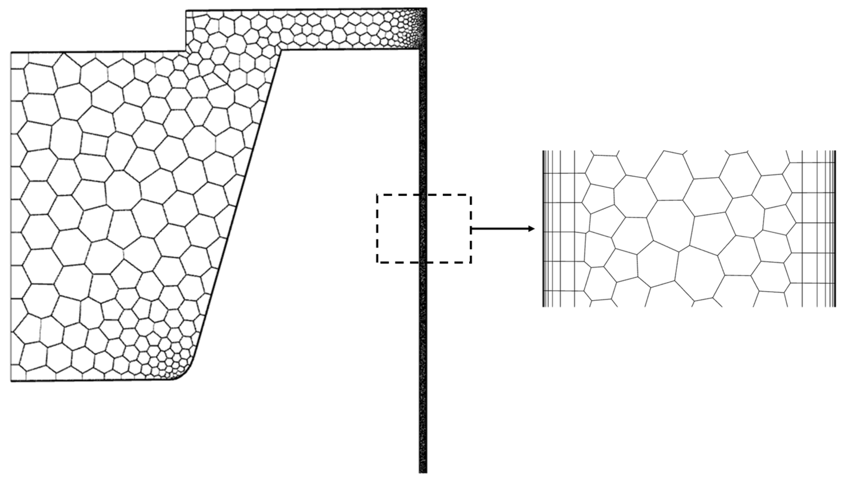
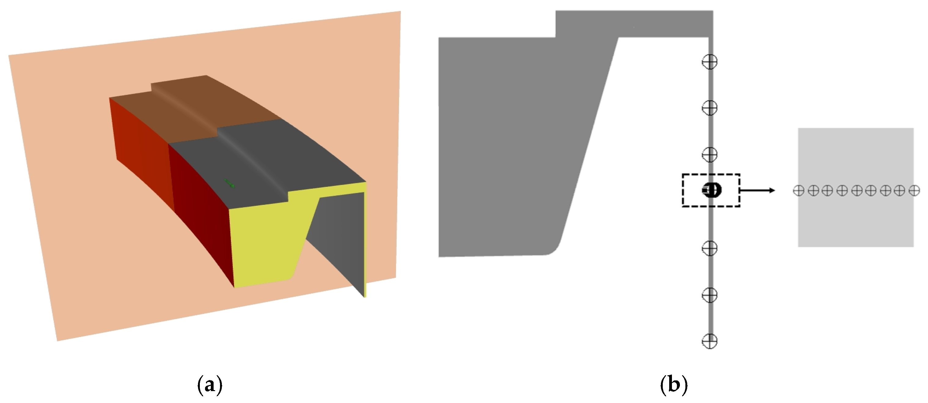
3.1. Computational Model

Computational fluid dynamics (CFD) has become an indispensable tool for analyzing complex flow phenomena in hydraulic machinery, especially in regions where experimental measurements are difficult to perform. In this study, a three-dimensional CFD simulation of the flow within the narrow annular gap between the seal rings and the upper bracket was carried out using ANSYS Fluent 2022R1 version. Owing to the significant shear and rotational effects involved, this section aims to validate theoretical predictions, reveal detailed flow structures, and further analyze the gap flow characteristics of the seal rings from a visualization perspective.
To simplify the computational model, the annular fluid domain is partitioned in recognition of its periodic symmetry: the full 360° geometry is divided into 36 equal 10° sectors, and one such 1/36 sector is selected as the computational domain. Periodic boundary conditions are imposed on its two radial-cut faces to emulate the full ring. A structured mesh is employed, with refinement near all walls to capture boundary-layer effects and high shear rates. This study focuses on the flow development from the gap inlet up to the point where the flow enters the cover cavity.
In Fluent Meshing, the Poly-Hexcore hybrid meshing method was used to mesh the computational model. Structured hexahedral meshes were used in the internal flow field or regular regions, while polyhedral mesh elements were applied in complex geometric surfaces or irregular regions. Ten layers of boundary layer were added near the wall to capture boundary effects and high shear rates. A local refinement method was used to refine the inlet section. Data monitoring was performed at three measurement points along the radial distribution of the middle height of the inlet section for three sets of meshes, verifying mesh independence and ensuring the convergence and accuracy of the data(see Table 1).
The total number of mesh cells for the three sets is 5,150,000, 12,906,281, and 41,181,751, with corresponding y+ values of 29, 16, and 0.7. It can be observed that the results of the computational model with medium mesh density stabilized. Considering the computational resources, the use of fine mesh is acceptable, so the computational mesh model with a total of 41,181,751 mesh cells was adopted. The specific mesh model is shown in Figure 3.

3.2. Solver Setup

Pressure-inlet and pressure-outlet boundary conditions were applied; the inner wall (seal-ring surface) was modeled as a rotating wall with an angular speed of 7.96 rad/s, while the outer wall was stationary. A no-slip condition was enforced on all walls. A uniform axial acceleration of 9.81 m/s2 drove the upward flow. The two radial-cut faces of the sector are defined as periodic boundaries, rotated by 10° about the z-axis.
A transient simulation was performed using the SST k-ω turbulence model. The SST k-ω model combines the advantages of the k-ε model and the k-ω model, providing higher accuracy in the near-wall region, making it especially suitable for handling turbulence characteristics within the boundary layer. Although the SST k-ω model may not capture every detail of the vortices when simulating small gap flows, LES and DNS offer higher accuracy but come with extremely high computational costs. In comparison, the SST k-ω model represents a good compromise between computational efficiency and accuracy. This is particularly important for rotating flows and complex flow scenarios. k-ω turbulence models are widely applied to study the unsteady flow field of hydraulic machinery, such as the research on the evolution of vortex rope and large curvature flow [30]. In the numerical simulation, pressure–velocity coupling was performed using the coupled method, with the PRESTO! interpolation scheme for pressure. The momentum equation and turbulence kinetic energy equation were discretized using the second-order upwind scheme to improve solution stability while ensuring accuracy. The time step was set to Δt = 0.0005 s, with 10,000 steps (total simulated time 5 s) and up to 20 inner iterations per time step.

3.3. Result

A “companion plane” is defined as the axial plane passing through the geometric center of the fluid domain within the seal-ring gap. On this plane, multiple monitoring points are arranged to record various physical quantities. Axial monitoring points point 1~point 7 (h = 0, 0.04, 0.08, 0.13, 0.16, 0.2, 0.24 m) and radial monitoring points point 4~point 4–9 (δ = 0, 0.5, 1, 1.5, 2, 2.5, 3, 3.5, 4 mm) were set. In subsequent results sections, this plane will be used to visualize key gap-flow characteristics—such as velocity and pressure—as well as rotation-induced turbulence and vortical structures. The selection of the companion plane and its schematic are shown in Figure 4.

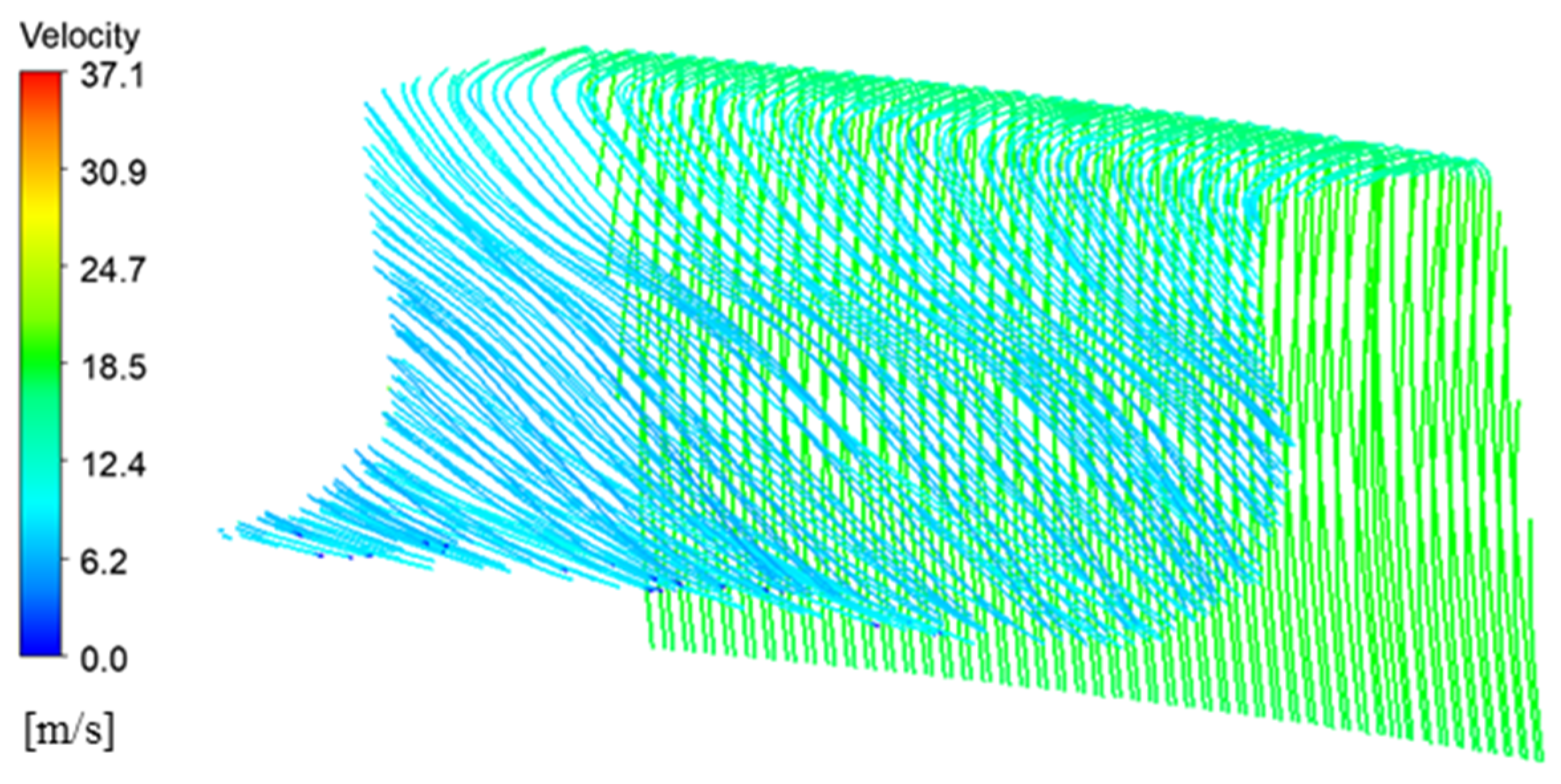
3.3.1. Shear-Driven Flow Characteristics

The rotating inner wall induces a dominant circumferential velocity component, forming a shear layer within the gap. To illustrate the radial distribution of the tangential velocity magnitude, nine monitoring points were placed along a radial line on the companion plane at the inlet section height z = 0.13 m (see Figure 4).
Figure 5 presents the measured velocities at these nine points: the absolute velocity exhibits an inverted “S”-shaped profile. Within the inlet region of the companion plane, the tangential velocity decreases non-uniformly in the radial direction, approximately nonlinearly from 37.06 m/s at the inner wall to 0 m/s at the outer wall. The decrease is slightly steeper near the inner wall and more gradual near the outer wall, indicating mild nonlinearity. This deviation from the ideal Couette-flow profile reflects the influence of turbulent fluctuations and geometric constraints, while the overall trend confirms the leading roles of rotational driving and wall confinement on the flow field.
The streamline plot in Figure 6 reveals a helical, upward flow trajectory: streamlines transition from a parallel arrangement at the inlet to tightly wound coils downstream, demonstrating the superimposed effects of axial pressure driving and rotation. The helical nature of the flow is particularly pronounced near the outlet. These observations are in good agreement with the expected flow behavior.

3.3.2. Influence of Short Channel Height on Flow Development

Figure 7 shows the axial pressure distribution in the inlet region: pressure decreases nearly linearly along the axis, with negligible radial variation. A localized pressure spike occurs at the top of the inlet due to geometric confinement; a distinct low-pressure region appears inside the cover cavity and at the outlet, confirming vortex formation.
Figure 8 presents axial-velocity profiles on the companion plane at three different heights. None of the velocity profiles exhibit a perfect parabolic shape, indicating the influence of the channel geometry on flow development. In the central region, the axial velocity magnitude decreases downstream, while velocities near the side walls fluctuate. Additionally, the profiles show a slight skew toward the outer wall, reflecting asymmetric development caused by the short channel height.

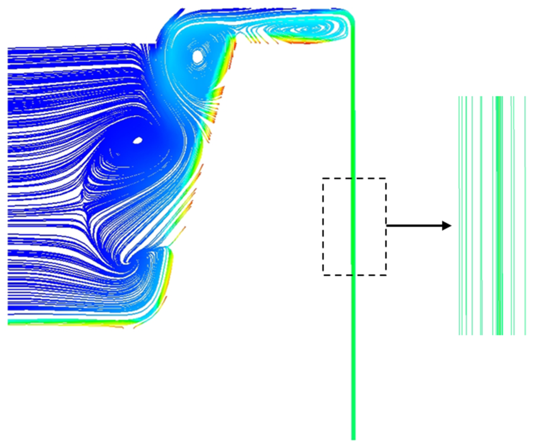
3.3.3. Rotation-Induced Vortices and Flow Instability

The rotating inner wall profoundly alters the gap flow, inducing complex vortical structures. Streamlines in Figure 9 illustrate spiral flow paths under rotational drive. In the inlet region, streamlines are dense and straight, indicating initial flow stability under geometric constraint. As the flow enters the cover cavity, rotational effects progressively generate vortices and helical trajectories, especially near the rotating wall. These vortices are driven by a combination of shear from the rotating wall and centrifugal forces; shear establishes velocity gradients, while centrifugal action amplifies vortex complexity.
To assess rotation-triggered instability in the inlet region, turbulent kinetic energy k was monitored at the nine radial points. Figure 10 plots k versus time for each point: the peak k of approximately 7.7 m2/s2 occurs adjacent to the rotating wall, indicating intense turbulent fluctuations and small-scale vortices. Turbulent kinetic energy decreases toward the channel center—forming a “U”-shaped radial profile—because the center experiences the smallest velocity gradient (hence weakest turbulence production) and greater energy dissipation. Near the outer wall, higher velocity gradients combined with centrifugally induced radial flow and turbulent diffusion elevate turbulence intensity above the central region.

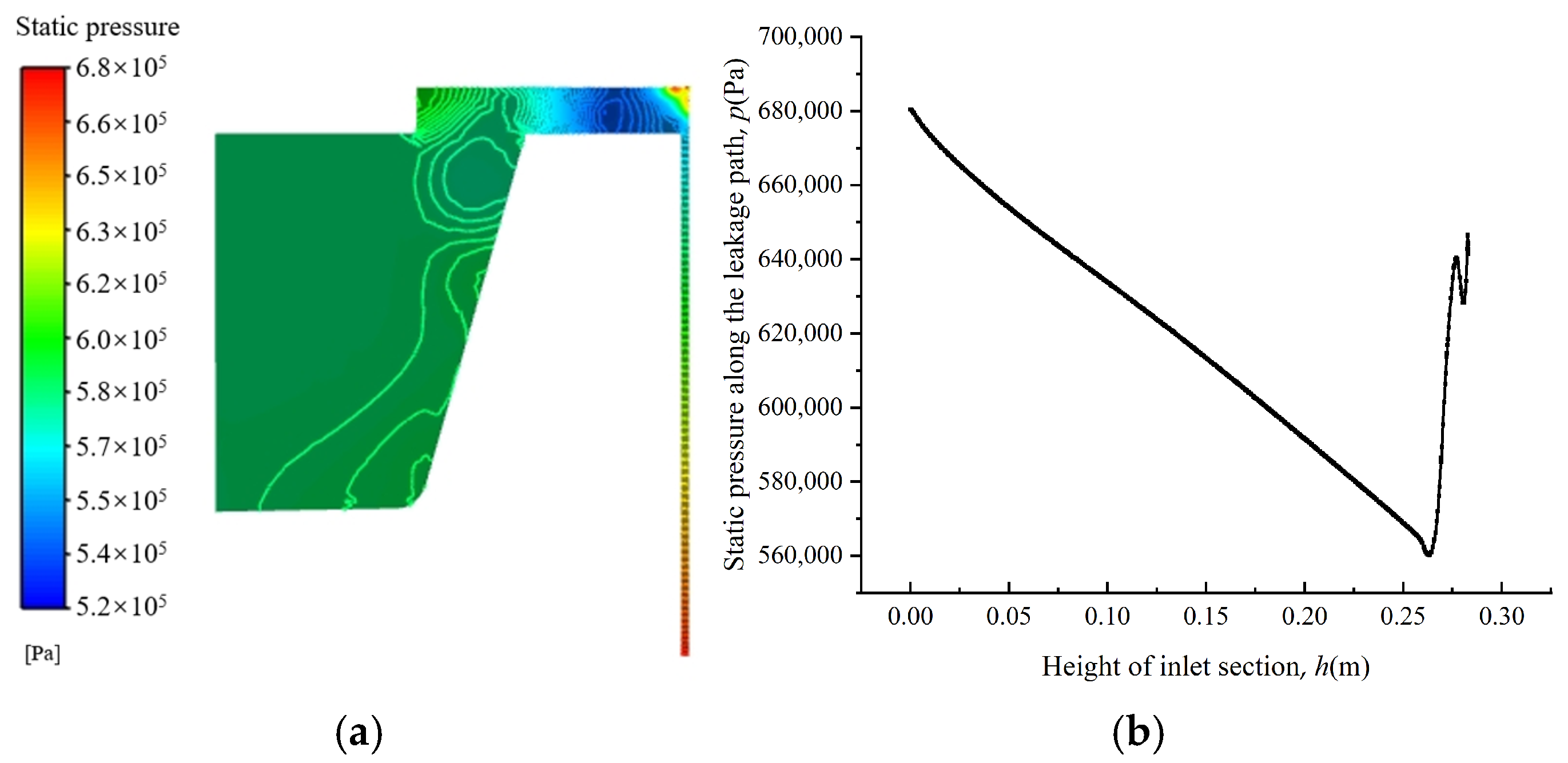
3.3.4. Pressure Pulsations and Flow Instability

Transient simulations also examine the relationship between pressure pulsations and flow instability. In this paper, three characteristic points were taken on the rotating wall at the height position along the flow channel to analyze the pressure pulsation, located in the middle and top positions of the inlet, respectively. Then, fast Fourier transform was used to perform frequency-domain analysis on the pressure time–history curve (see Figure 11).
Time-series plots show that pressure fluctuation amplitudes increase along the axial direction—weak at the gap inlet but markedly stronger at the inlet–outlet interface—coinciding with the rise in turbulent kinetic energy and indicating that turbulence energy accumulation intensifies downstream instability. Frequency spectra reveal dominant pulsation frequencies in the 1.1–1.5 Hz band for all three monitoring points, closely matching the rotation frequency of 1.27 Hz. This confirms that pressure pulsations are primarily driven by the rotating inner wall. The amplitude of the dominant frequency slightly decreases from inlet to outlet, reflecting diminished low-frequency energy content due to turbulent redistribution.

3.4. Discussion

The work conducted in this study provides a visualization of the different physical parameters of the leakage ring gap. In [18], a large eddy simulation (LES) of leakage flow in step-type labyrinth seals was presented, showing the velocity distribution at the step seal position, which is consistent with the results obtained in this study. Additionally, in [31], a numerical simulation of Taylor—Couette—Poiseuille flow at Re = 10,000 was conducted using the LES model. The study focused on the effects of high rotation on the mean flow, turbulence statistics, and vortex structure. It was found that an increase in rotational speed increased the axial velocity gradient at the wall, causing the axial velocity distribution uz in the central gap region to tend toward horizontal. The tangential velocity distribution obtained in the article aligns closely with the results of this study. Additionally, the frequency-domain analysis of the pressure fluctuations in the gap flow reveals that the frequency response of the fluctuations aligns with the existing literature [21,22] on the pulsing frequency response of labyrinth seal systems. The main frequency of the pulsations is roughly consistent with the rotational speed frequency, which reflects the accuracy of the research content.
By quantitatively comparing our results with the existing literature and providing clear explanations of boundary conditions, turbulence models, and geometric assumptions, we have not only validated the core results but have also clearly defined the scope and directions for model improvements, offering clear guidance for future research.

4. Conclusions and Outlook

4.1. Conclusions

This study systematically revealed the complex flow characteristics and multi-scale coupling mechanisms within the gap between the sealing ring and the upper frame of ultra-large mixed-flow turbines through theoretical modeling and three-dimensional transient CFD simulations. The main conclusions are as follows:
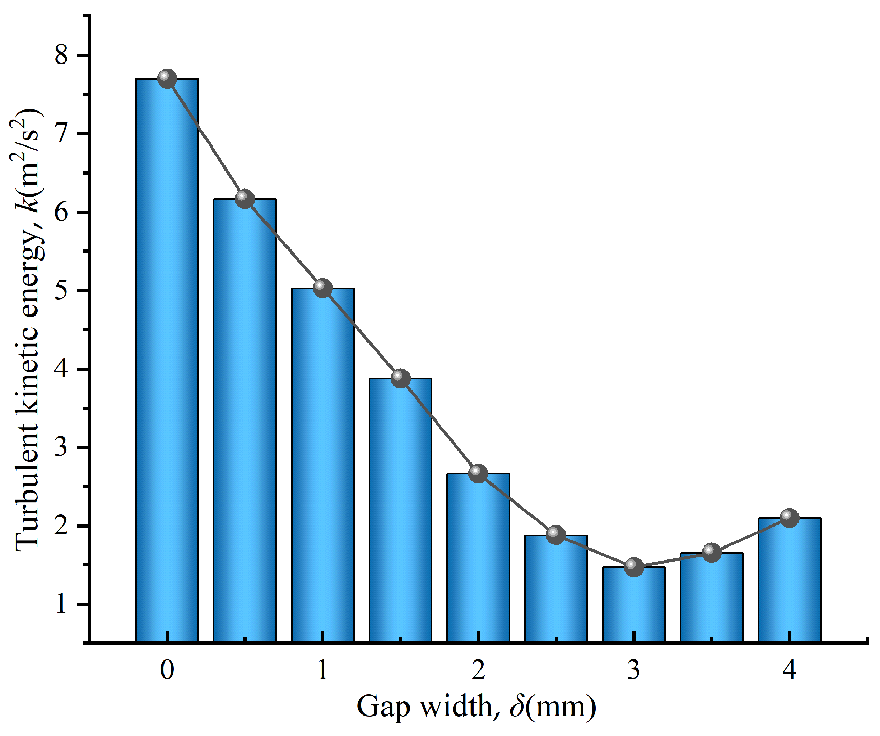
  • The CFD simulations not only validate the accuracy of the theoretical analysis but also enrich understanding of flow field characteristics through visualization. The simulation results demonstrate non-parabolic axial velocity distributions, spiral streamline trajectories, and a low-pressure zone in the upper-crown cavity, confirming the presence of vortices and the restrictive effect of short channels on flow development. The “U”-shaped distribution of turbulent kinetic energy and the dynamic variations in pressure fluctuations further reveal the rotation-induced turbulence enhancement effect, providing a powerful tool for the quantitative analysis of complex flow fields.
  • The high-speed rotation of the inner wall is the dominant factor in the flow field within the gap. The theoretical analysis derived a nearly linear distribution of tangential velocity with a shear rate as high as 9250 s−1. CFD simulations further revealed an inverted “S”-shaped nonlinear distribution of tangential velocity along the radial direction, deviating from the linear characteristics of classical Couette flow. This phenomenon is attributed to the combined effects of turbulent diffusion and centrifugal force-induced secondary flows, highlighting the significant reshaping effect of rotation on boundary layer flow. Additionally, the streamline trajectories exhibited a spiral ascending flow pattern, particularly near the rotating wall, where the peak turbulent kinetic energy reaches 7.7 m2/s2, confirming the presence of complex vortex structures and turbulence enhancement induced by rotation. These findings provide new insights into understanding energy dissipation and leakage control in the internal flow of rotating machinery.
  • This study incorporated the multi-scale effects introduced by the short channel height and high-speed rotation into the analytical framework and employed a modified Taylor number to assess flow stability. The results indicate that although the short channel geometry suppresses the formation of complete Taylor vortices, local small-scale vortices and flow instabilities still persist, particularly near the inner wall. Spectral analysis showed that the dominant frequency of pressure fluctuations is highly correlated with the rotational frequency of 1.27 Hz, and the amplitude decreases with increasing channel height, revealing the regulatory mechanism of the coupling between rotation and geometric constraints on flow stability.
This study has demonstrated the variation trends of the flow structure and velocity distribution in the small-gap region, providing qualitative guidance for the geometric design of subsequent sealing rings. Specific structural optimization and parameter control should consider various factors such as actual operating conditions and system stability, and further research should be conducted in the future.

4.2. Future Perspectives

This study has focused on analyzing the flow dynamics characteristics within the sealing ring and upper frame gap of a super-large mixed-flow water turbine through theoretical modeling and three-dimensional transient CFD simulations. The importance and necessity of the flow characteristics in the sealing ring gap were analyzed, revealing their impact on turbine performance, including leakage, energy loss, and operational efficiency, as well as their role in ensuring safety and stability. The influence of rotating walls was examined, demonstrating how they alter velocity and pressure distributions, generating complex flow patterns such as vortices. Furthermore, turbulence and flow instability were discussed, identifying their contributions to energy dissipation and mechanical challenges such as vibration and noise. These studies highlight the complex interactions between rotation, geometry, and flow behavior in turbine sealing systems.
In the future, by leveraging data on turbulent kinetic energy, velocity gradients, and pressure pulsations obtained in this study, quantitative analyses of turbulence and instability can be conducted. Through spectral analysis, the relationship between dominant unstable frequencies and parameters such as rotational speed and gap width can be revealed. These achievements not only deepen the understanding of flow instability mechanisms but also guide the exploration of flow control strategies, such as adjusting gap geometry or introducing guide devices, to mitigate instability and reduce vibration risks, thereby enhancing the operational efficiency and safety of water turbines.
In the subsequent dynamic analysis of the sealing ring, the flow field data from this study provides precise pressure load information, laying the foundation for fluid–structure interaction analysis. Future research can apply the dynamic pressure from the CFD simulations to the finite element model of the sealing ring to calculate its stress distribution and deformation characteristics to assess whether its structural strength meets the long-term operational requirements. Additionally, by analyzing the vibration characteristics induced by pressure pulsations and combining them with material fatigue properties, it is possible to predict the fatigue life of the sealing ring, particularly focusing on potential failure risks in high-turbulence areas near the inner wall. These analytical results will provide a basis for optimizing the design of the sealing ring, such as adjusting material thickness, adding stiffeners, or optimizing geometric shapes to enhance its fatigue resistance. In summary, the flow field data from this study not only provide high-precision boundary conditions and empirical evidence for stability theoretical models and dynamic analyses but also provide guidance for optimizing the design of sealing systems, which is instrumental in significantly improving the performance and reliability of water turbines.

Author Contributions

Conceptualization, L.C.; Methodology, W.W. and Y.W.; Validation, B.X (Bing Xue). and L.X.; Formal analysis, B.X. (Baosheng Xie); Investigation, J.D.; Writing—original draft, W.W. and B.X. (Baosheng Xie); Writing—review & editing, L.C. and Y.W.; Visualization, W.W.; Supervision, Y.W.; Project administration, L.C. and Y.W. All authors have read and agreed to the published version of the manuscript.

Funding

This research was supported by the Open Research Fund of Hubei Technology Innovation Center for Smart Hydropower, Grant Number: HBCXZX-JJ-202417.

Data Availability Statement

Due to privacy and confidentiality agreements related to engineering design, detailed data supporting the results re-ported in this article, including schematics and related technical documents, cannot be made publicly available. Further inquiries can be directed to the corresponding author.

Conflicts of Interest

Authors Leilei Chen, Jian Deng, Bing Xue, and Liuming Xu were employed by China Yangtze Power Co., Ltd., Yichang. The remaining authors (Wenhao Wu, Baosheng Xie, Yuchuan Wang) declare that the research was conducted in the absence of any commercial or financial relationships that could be construed as a potential conflict of interest.

References

  1. Mao, X.; Zhong, P.; Li, Z.; Liu, Z.; Hu, J.; Yan, J. Development and application of modified partially averaged Navier Stokes in the internal flow field of a Francis turbine. Phys. Fluids 2025, 37, 037122. [Google Scholar] [CrossRef]
  2. International Energy Agency. World Energy Outlook 2022; International Energy Agency: Paris, France, 2022. [Google Scholar]
  3. Rijal, M.; Neopane, H.; Chitrakar, S.; Pandey, A.; Dev, J. Numerical study of erosion on labyrinth seals of Francis turbine. J. Phys. Conf. Ser. 2023, 2629, 012021. [Google Scholar] [CrossRef]
  4. Zhou, D.; Chen, H.; Zhang, J.; Jiang, S.; Gui, J.; Yang, C.; Yu, A. Numerical Study on Flow Characteristics in a Francis Turbine during Load Rejection. Energies 2019, 12, 716. [Google Scholar] [CrossRef]
  5. Dörfler, P.; Sick, M.; Coutu, A. Flow-Induced Pulsation and Vibration in Hydroelectric Machinery: Engineer’s Guidebook for Planning, Design and Troubleshooting; Springer: London, UK, 2013. [Google Scholar] [CrossRef]
  6. Ohiemi, I.E.; Yang, S.; Singh, P.; Li, Y. Experimental investigation on the effect of axial gap on performance and unsteady pressure pulsations of low head axial flow hydraulic turbine. SSRN Electron. J. 2022. [Google Scholar] [CrossRef]
  7. Tang, B.; Liao, J.; Zhao, Z.; Deng, Q.; Li, J.; Feng, Z. Windage and Leakage Losses in Impeller Back Gap and Labyrinth Seal Cavities of Supercritical CO2 Centrifugal Compressors. Appl. Sci. 2025, 15, 3678. [Google Scholar] [CrossRef]
  8. Cui, J.; Tang, H. A review on flow instability in hydro-viscous drive. Phys. Fluids 2024, 36, 041301. [Google Scholar] [CrossRef]
  9. Xie, Y.; Du, Q.; Xie, L.; Wang, Z.; Li, S. Onset of turbulence in rotor-stator cavity flows. J. Fluid Mech. 2024, 991, A3. [Google Scholar] [CrossRef]
  10. Martinand, D.; Serre, E.; Lueptow, R.M. Absolute and convective instability of cylindrical Couette flow with axial and radial flows. Phys. Fluids 2009, 21, 104102. [Google Scholar] [CrossRef]
  11. Nagata, M. Taylor-Couette flow in the narrow-gap Limit. Philos. Trans. R. Soc. A 2023, 381, 20220134. [Google Scholar] [CrossRef]
  12. Cotrell, D.L.; McFadden, G.B. Axial flow effects on the stability of circular Couette flow with viscous heating. Phys. Fluids 2006, 18, 084106. [Google Scholar] [CrossRef]
  13. Trivedi, C. Time-dependent inception of vortex rings in a Francis turbine during load variation: Large eddy simulation and experimental validation. J. Hydraul. Res. 2020, 58, 790–806. [Google Scholar] [CrossRef]
  14. Trivedi, C.; Cervantes, M.J.; Dahlhaug, O.G. Numerical Techniques Applied to Hydraulic Turbines: A Perspective Review. Appl. Mech. Rev. 2016, 68, 010802. [Google Scholar] [CrossRef]
  15. Moore, J.J. Three-dimensional CFD rotordynamic analysis of gas labyrinth seals. J. Vib. Acoust. 2003, 125, 427–433. [Google Scholar] [CrossRef]
  16. Ding, J. Numerical Simulation and Experiment of Gas Film Flow Field on the Surface of Floating Ring Micro Groove Hydrodynamic Seal. Ph.D. Thesis, Lanzhou University of Technology, Lanzhou, China, 2019. [Google Scholar]
  17. Schiffer, J.; Benigni, H.; Jaberg, H.; Schneidhofer, T.; Ehrengruber, M. Numerical simulation of the flow in a Francis turbine including the runner seals on crown and band side. IOP Conf. Ser. Earth Environ. Sci. 2015, 26, 012022. [Google Scholar] [CrossRef]
  18. Kim, J.-H.; Ahn, J. Large Eddy Simulation of Leakage Flow in a Stepped Labyrinth Seal. Processes 2021, 9, 2179. [Google Scholar] [CrossRef]
  19. Nicoli, A.; Johnson, K.; Jefferson-Loveday, R. Computational modelling of turbulent taylor-couette flow for bearing chamber applications: A comparison of unsteady Reynolds-averaged Navier-Stokes models. Proc. Inst. Mech. Eng. Part A J. Power Energy 2022, 236, 985–1005. [Google Scholar] [CrossRef]
  20. Safari, A.; Saidi, M.H.; Salavatidezfouli, S.; Ma, W.; Yao, S. A comprehensive experimental and numerical study of Taylor-Couette flow on superhydrophobic surfaces. AIP Adv. 2025, 15, 055012. [Google Scholar] [CrossRef]
  21. Jia, X.; Zhang, H.; Zheng, Q.; Fan, S.; Tian, Z. Investigation on Rotor-Labyrinth Seal System with Variable Rotating Speed. Int. J. Turbo Jet Eng. 2020, 37, 209–219. [Google Scholar] [CrossRef]
  22. Zhang, X.; Jiao, Y.; Qu, X.; Huo, G.; Zhao, Z. Simulation and Flow Analysis of the Hole Diaphragm Labyrinth Seal at Several Whirl Frequencies. Energies 2022, 15, 379. [Google Scholar] [CrossRef]
  23. Zheng, K.; Ma, H.; Sun, H.; Qin, J. Investigation of Flow Characteristics in Rotating Distributary and Confluence Cavities. Energies 2025, 18, 1287. [Google Scholar] [CrossRef]
  24. Xu, Z.; Xu, L.; Sun, J.; Liu, M.; Liao, T.; Hu, X. Research on Micro Gap Flow Field Characteristics of Cylindrical Gas Film Seals Based on Experimental and Numerical Simulation. Aerospace 2024, 11, 40. [Google Scholar] [CrossRef]
  25. Perini, M.; Binder, N.; Bousquet, Y.; Schwartz, E. Rotating Instabilities in Shrouded Low Pressure Turbine at Design and Off-Design Conditions. J. Turbomach. 2023, 145, 111006. [Google Scholar] [CrossRef]
  26. Demay, Y.; Iooss, G.; Laure, P. The Couette Taylor Problem in the Small Gap Approximation. In Ordered and Turbulent Patterns in Taylor-Couette Flow; Andereck, C.D., Hayot, F., Eds.; NATO ASI Series; Springer: Boston, MA, USA, 1992; Volume 297. [Google Scholar] [CrossRef]
  27. Munson, B.R.; Young, D.F.; Okiishi, T.H.; Huebsch, W.W. Fundamentals of Fluid Mechanics, 8th ed.; Wiley: Hoboken, NJ, USA, 2018; ISBN 978-1-119-40787-3. [Google Scholar]
  28. Taylor, G.I. The Stability of a Viscous Liquid Contained Between Two Rotating Cylinders. Philos. Trans. R. Soc. Lond. A 1923, 223, 289–343. [Google Scholar] [CrossRef]
  29. Chandrasekhar, S. Hydrodynamic and Hydromagnetic Stability; Dover Publications: New York, NY, USA, 1981; p. 24. [Google Scholar]
  30. Mao, X.; Liu, Z.; Li, T.; Mao, G.; Chen, D. A brief review of numerical solving methods for internal fluid of pumped storage unit. Int. J. Energy Res. 2020, 44, 7549–7566. [Google Scholar] [CrossRef]
  31. Gavrilov, A.; Ignatenko, Y. Numerical Simulation of Taylor-Couette-Poiseuille Flow at Re = 10,000. Fluids 2023, 8, 280. [Google Scholar] [CrossRef]
Figure 1. Seal-ring clearance structure diagram.
Energies 18 03726 g001
Figure 2. Theoretical calculation model. The arrow indicates the direction of rotation of the rotor, and the angular velocity of rotation is ω.
Energies 18 03726 g002
Figure 3. Mesh of flow domain.
Energies 18 03726 g003
Figure 4. Selection of companion plane (a) and schematic diagram (b).
Energies 18 03726 g004
Figure 5. Speed distribution. Tangential velocity (a) and total velocity (b).
Energies 18 03726 g005
Figure 6. Distribution of internal flow field traces.
Energies 18 03726 g006
Figure 7. Pressure distribution. Static pressure distribution (a) and axial pressure distribution (b).
Energies 18 03726 g007
Figure 8. Axial velocity profiles at different heights of the inlet section (a) and along the centerline of the inlet section (b).
Energies 18 03726 g008
Figure 9. Flow traces in the accompanying plane.
Energies 18 03726 g009
Figure 10. Changes in turbulent kinetic energy at different measuring points (point 4~4–9).
Energies 18 03726 g010
Figure 11. Pressure pulsation analysis. Pulsation time domain diagram (a) and pulsation frequency domain diagram (b).
Energies 18 03726 g011
Table 1. Discretization error for numerical study.
Measurement ParametersCoarseMediumFinee21 (%)GCI21 (%)
Y-Velocity at Point 1 (m/s)10.21489.387559.037853.8693.54
Y-Velocity at Point 2 (m/s)2.706613.066863.085440.6020.041
Y-Velocity at Point 3 (m/s)0.2869730.3856680.3900281.1180.065
Mass Flow Rate at inlet (kg/s)54.7353.9753.580.7280.96
Mass Flow Rate at outlet (kg/s)54.7353.9753.580.7280.96
Disclaimer/Publisher’s Note: The statements, opinions and data contained in all publications are solely those of the individual author(s) and contributor(s) and not of MDPI and/or the editor(s). MDPI and/or the editor(s) disclaim responsibility for any injury to people or property resulting from any ideas, methods, instructions or products referred to in the content.

