Article

Research on the Influence of Impeller Oblique Cutting Angles on the Performance of Double-Suction Pumps

1
Shandong Shuanglun Co., Ltd., Weihai 264203, China
2
National Research Center of Pumps, Jiangsu University, Zhenjiang 212013, China
*
Author to whom correspondence should be addressed.
Energies 2025, 18(15), 3907; https://doi.org/10.3390/en18153907
Submission received: 3 June 2025 / Revised: 9 July 2025 / Accepted: 21 July 2025 / Published: 22 July 2025
(This article belongs to the Special Issue Optimization Design and Simulation Analysis of Hydraulic Turbine)

Abstract

Double-suction centrifugal pumps are extensively employed in industrial applications owing to their high efficiency, low vibration, superior cavitation resistance, and operational durability. This study analyzes how impeller oblique cutting angles (0°, 6°, 9°, 12°) affect a double-suction pump at a fixed 4% trimming ratio and constant average post-trim diameter. Numerical simulations and tests reveal that under low-flow (0.7Qd) and design-flow conditions, the flat-cut (0°) minimizes reflux ratio and maximizes efficiency by aligning blade outlet flow with the mainstream. Increasing oblique cutting angles disrupts this alignment, elevating reflux and reducing efficiency. Conversely, at high flow (1.3Qd), the 12° bevel optimizes outlet flow, achieving peak efficiency. Pressure pulsation at the volute tongue (P11) peaks at the blade-passing frequency, with amplitudes significantly higher for 9°/12° bevels than for 0°/6°. The flat-cut suppresses wake vortices and static–rotor interaction, but oblique cutting angle choice critically influences shaft-frequency pulsation. Entropy analysis identifies the volute as the primary loss source. Larger oblique cutting angles intensify wall effects, increasing total entropy; pump chamber losses rise most sharply due to worsened outlet velocity non-uniformity and turbulent dissipation. The flat-cut yields minimal entropy at Qd. These findings provide a basis for tailoring impeller trimming to specific operational requirements. Furthermore, the systematic analysis provides critical guidance for impeller trimming strategies in other double-suction pumps and pumps as turbines in micro hydropower plants.

1. Introduction

Fluid machinery, as one of the primary energy-consuming equipment types in industrial sectors, requires performance optimization to achieve energy conservation. Among these systems, double-suction centrifugal pumps are extensively utilized in diverse industrial applications—including water conservancy irrigation systems, municipal water supply and drainage, industrial water circulation, and inter-basin water transfer projects—due to their high efficiency, low vibration, excellent cavitation resistance, ease of maintenance, and prolonged service life [1]. However, operational scenarios frequently involve mismatches, where pump performance parameters exceed actual demand. To address this, impeller trimming has become a prevalent engineering solution for adjusting hydraulic characteristics and expanding operational adaptability.
Impeller trimming remains a prevalent technique for centrifugal pump performance adjustment, with extensive research conducted on trimming laws and their hydraulic impacts. In [2], the authors investigated multiple trimming configurations, revealing distinct efficiency variations across operating conditions. A survey in [3] demonstrated that front shroud modifications significantly affect low-specific-speed pump performance. In [4], the authors established that increased tip clearance through trimming reduces head while amplifying vibrations. In [5], the authors identified nonlinear deviations from affinity laws regarding radial forces and pressure pulsations under trimmed diameters. A survey optimized operational efficiency through controlled trimming, though excessive cuts degraded performance [6]. In [7], the authors observed shifted efficiency zones and reduced pressure pulsations in self-priming pumps post-trimming. An investigation reported a 1.7% prolonged self-priming duration with a diameter reduction of 6% [8]. In [9], the authors documented the best efficiency point migration toward lower flows with trimming. A survey in [10] identified turbine-mode efficiency gains through partial trimming. In [11], the authors achieved pressure fluctuation mitigation via trailing-edge modifications. In [12], the authors reduced axial forces through strategic back-shroud trimming. A survey minimized hydraulic impacts on multistage impellers through optimized trimming [13]. A survey demonstrated that oblique trimming alleviates rotating stall in inter-blade channels [14].
In engineering practice, the initial cutting amount is typically determined by referencing the standard trimming law. However, derived under idealized operating assumptions, this law’s calculated results often exhibit certain deviations. To mitigate impeller damage risks from excessive trimming, a multi-stage trimming approach is universally adopted. This involves achieving target dimensions through two or more incrementally staged trimming operations, with mandatory hydraulic performance testing after each trimming procedure to evaluate compliance with predetermined performance indicators.
The primary limitation of this traditional progressive trimming method lies in its repetitive “trimming–testing” cycles, which not only consume substantial labor hours but also significantly increase economic costs—particularly pronounced during trimming operations for pumps with higher specific speeds.
To address these deficiencies and provide engineering guidance for impeller trimming technology, a survey established a corrective calculation diagram for optimizing centrifugal pump and fan impeller diameters through systematic analysis of experimental data [15]. However, subsequent research revealed limitations in the applicability of correction coefficients due to significant variations in critical geometric parameters (including hub-to-diameter ratio and blade number) within test samples. Furthermore, the computational accuracy of this correction method deteriorates with increasing the specific speed of turbomachinery, exhibiting more significant discrepancies particularly in high-specific-speed pumps.
Current research on internal flow characteristics of double-suction pumps post-cutting remains limited, with existing studies predominantly focusing on external performance parameters and pressure pulsations [16], while insufficient attention has been given to transient flow phenomena such as vortex structures, recirculation patterns, and jet–wake interactions. Compared to their single-suction counterparts, double-suction pumps exhibit greater structural complexity, where impeller trimming significantly alters internal flow dynamics. The selection of optimal cutting angles critically influences energy loss mitigation, operational longevity, and maintenance cost reduction. Consequently, in-depth investigation into the influence of impeller oblique cutting on the hydraulic performance of double-suction pumps holds significant implications for subsequent engineering design and energy retrofit projects. Furthermore, within the context of low-carbon transition initiatives, research on impeller cutting for double-suction pumps proves critically important when these pumps operate in turbine mode.
As illustrated in Figure 1, this study employs high-resolution numerical simulations to systematically investigate the influence of impeller oblique cutting on double-suction pump performance. The research comprehensively examines three interconnected aspects: (1) the evolution patterns of external characteristics (head, efficiency) with varying oblique cutting angles, (2) the underlying mechanisms governing internal flow modifications including vortex dynamics and energy dissipation, and (3) the resulting pressure pulsation phenomena particularly at critical monitoring locations. This tripartite analysis bridges macro-scale performance degradation with micro-scale flow instabilities, providing holistic insights for hydraulic optimization.

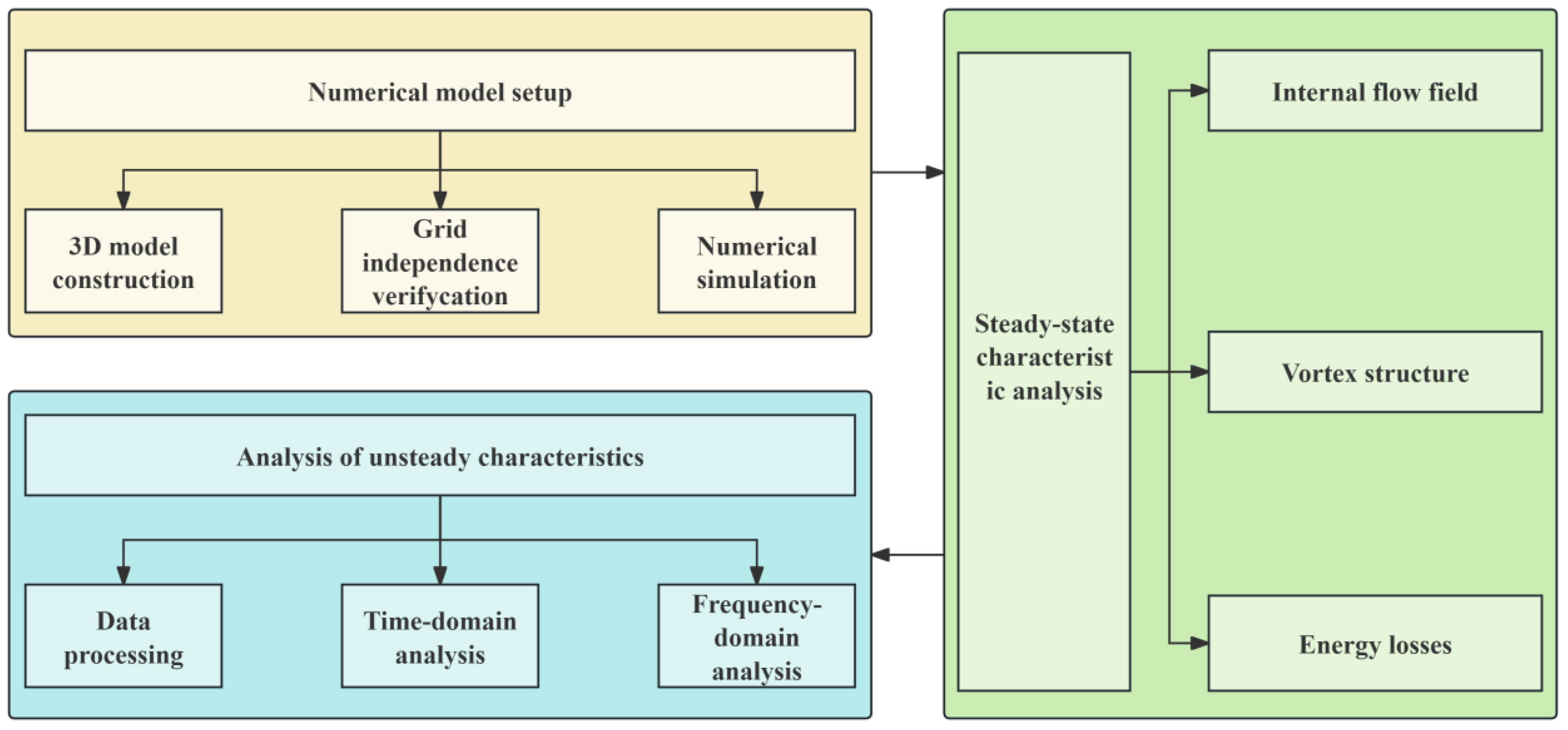
2. Model and Numerical Simulation
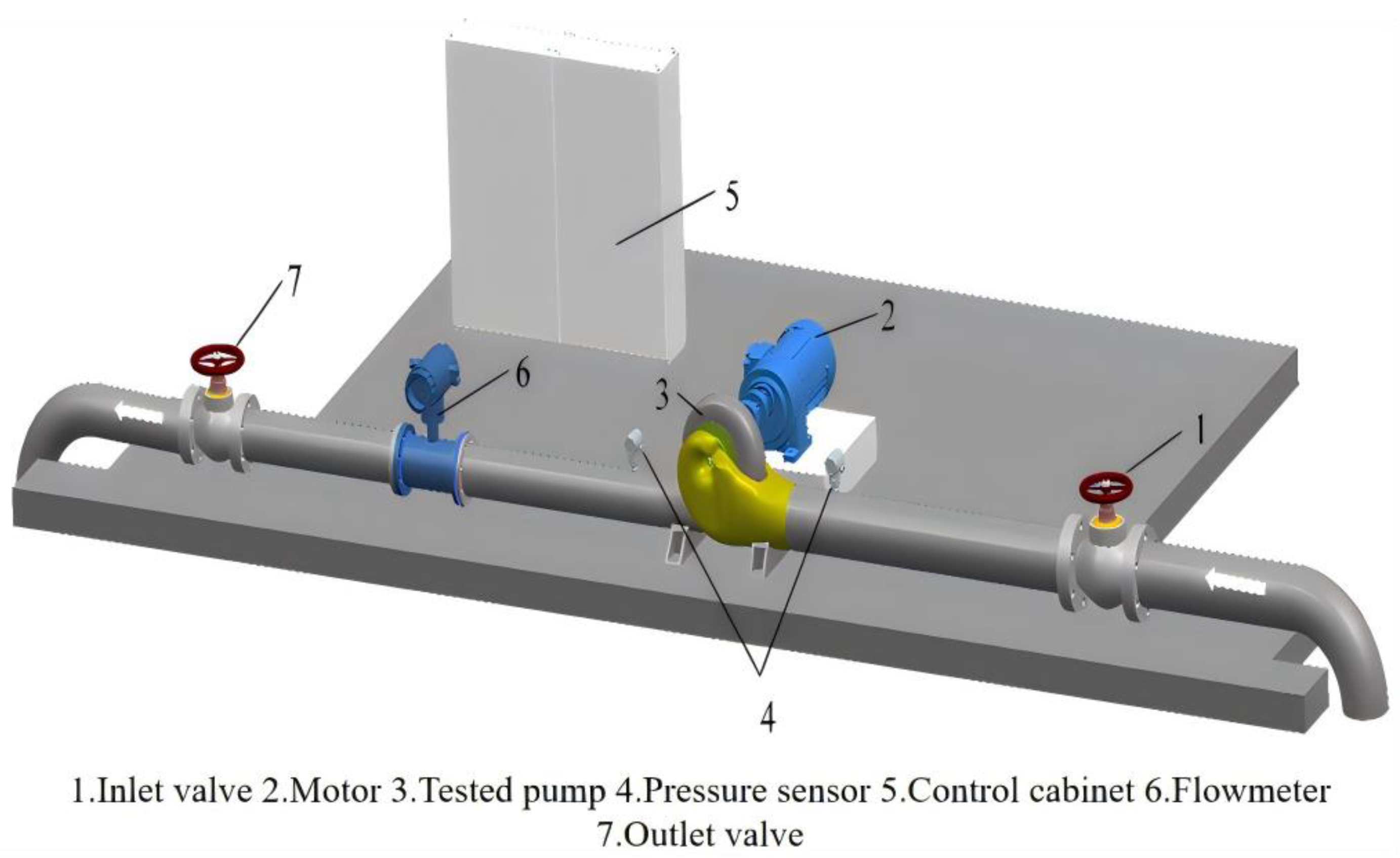
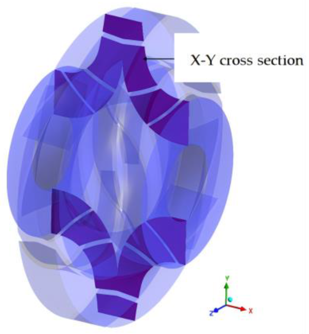
2.1. Physical Model

The investigation focuses on a 250GS40 horizontal split-case single-stage double-suction pump manufactured by Shandong Shuanglun Co., Ltd., (Weihai, China). The computational domain comprises four principal components: semi-spiral suction chamber, pump chambers, impeller passages, and volute flow channels. Considering the recirculation effects at discharge, a 5D extension pipe (D = outlet diameter) was appended to the volute outlet to minimize boundary condition interference, with detailed structural configuration presented in Figure 2. The prototype operates at design parameters Qd = 500 m3/h, H = 40 m, and rotational speed n = 1480 rpm, yielding specific speed ns = 90. Complete geometric specifications are cataloged in Table 1.

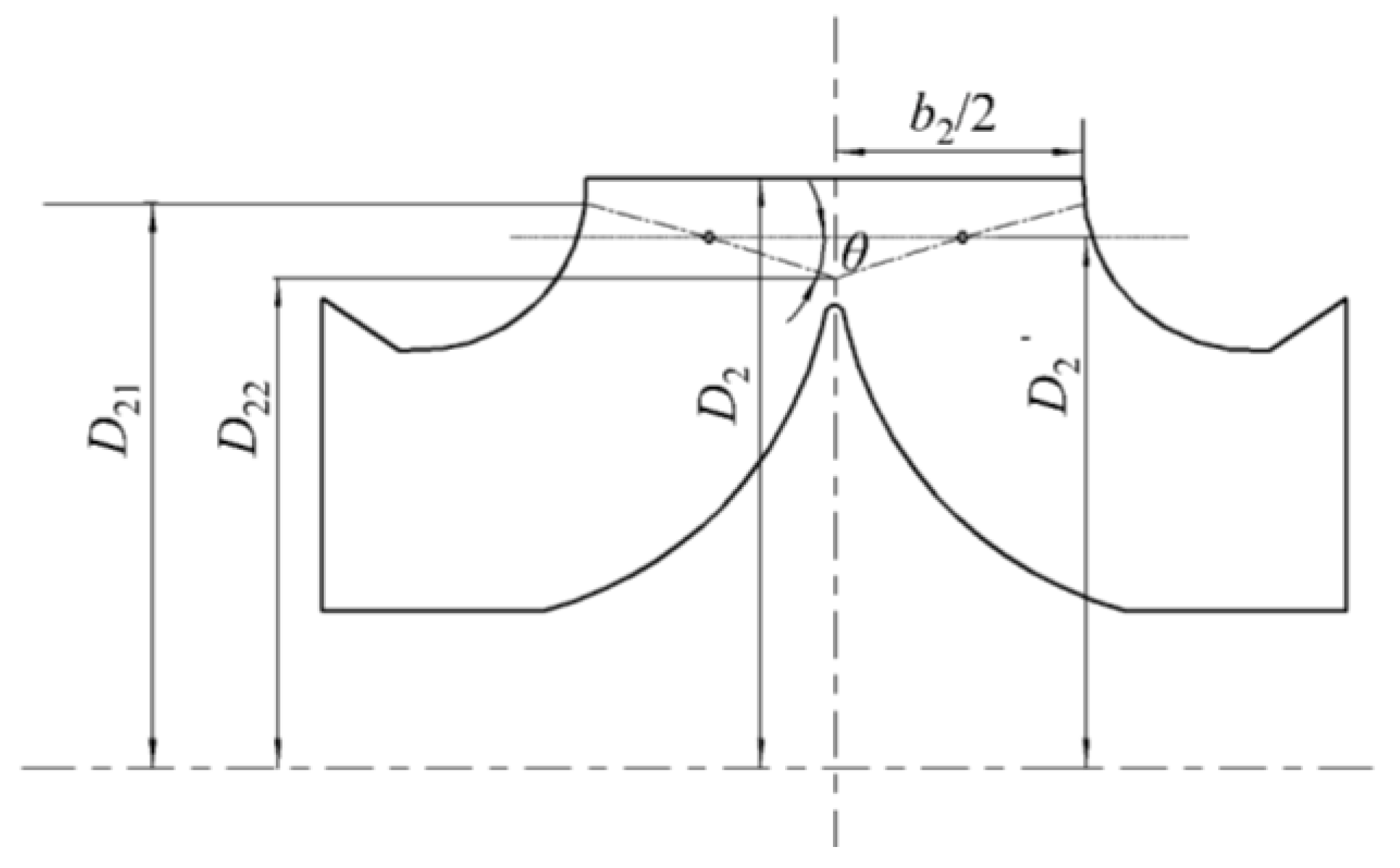
2.2. Impeller Cutting Scheme

Forward oblique cutting of double-suction impeller outlets involves symmetrical material removal from the front shroud to the back shroud under constant post-trimming mean diameter D2’, creating distinct angular configurations (θ), as shown in Figure 3. The geometric parameters are defined as follows: trimming angle θ, original diameter D2, trimmed mean diameter D2’, shroud/hub diameters D21 and D22, trimming allowance ΔD, and trimming ratio φD. The governing relationships are as follows:
Δ D = D 2 D 2
φ D = Δ D D 2
D 2 = ( D 21 + D 22 ) 2
0 < θ < arctan 2 Δ D b 2
Table 2 presents recommended allowable cutting ranges for impellers across specific speeds. Extensive engineering practice and numerical analyses demonstrate an inverse correlation between permissible trimming ratios and specific speeds, whereby higher ns values correspond to reduced allowable trimming percentages. Practical implementations require parameter adjustments based on operational demands and performance targets. Within permissible trimming limits, this study adopts a 4% trimming ratio while maintaining constant post-cutting mean diameter. Four angular configurations—0° (planar cutting), 6° (oblique cutting), 9° (oblique cutting), and 12 (oblique cutting)—were systematically designed for comparative analysis.

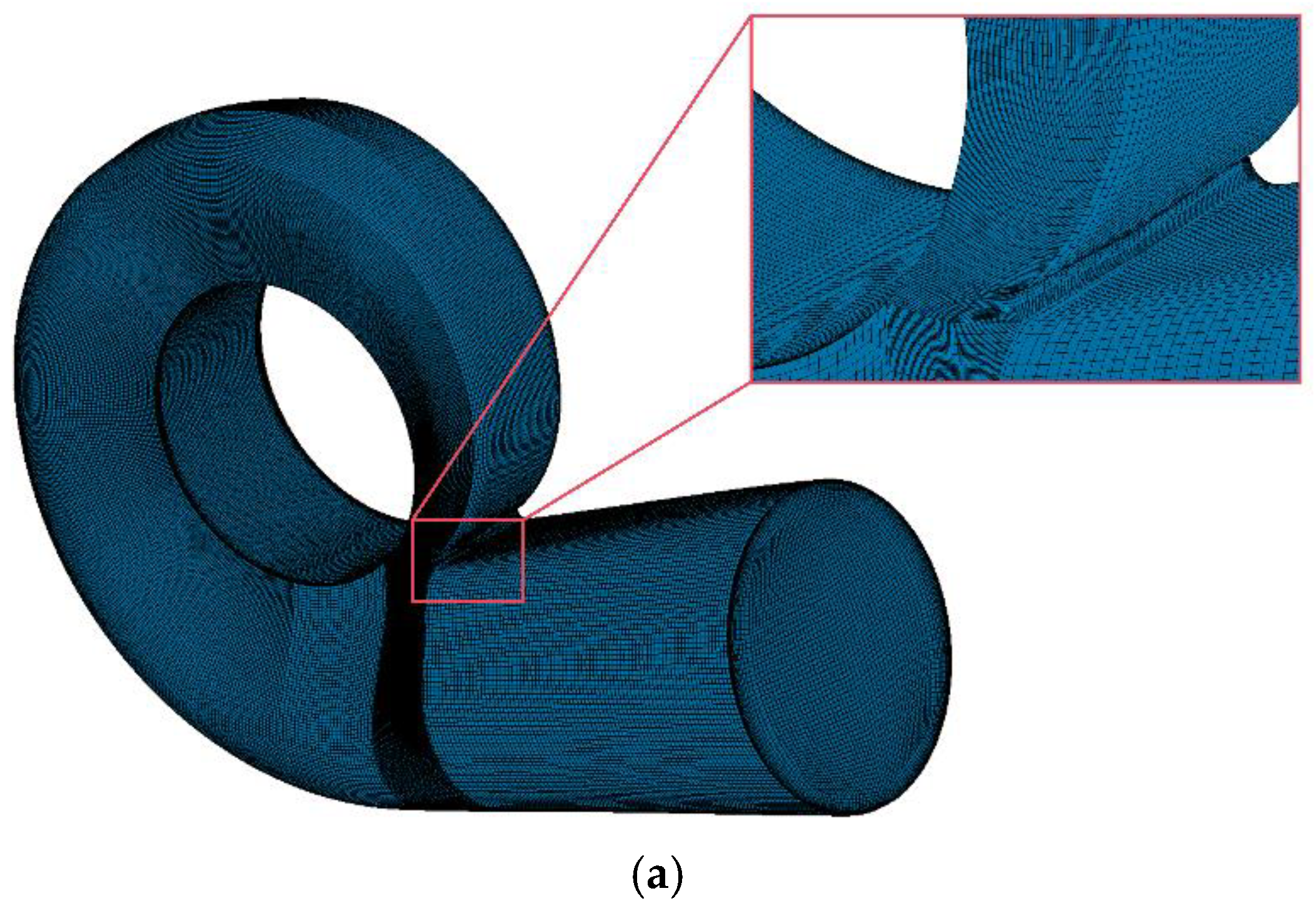
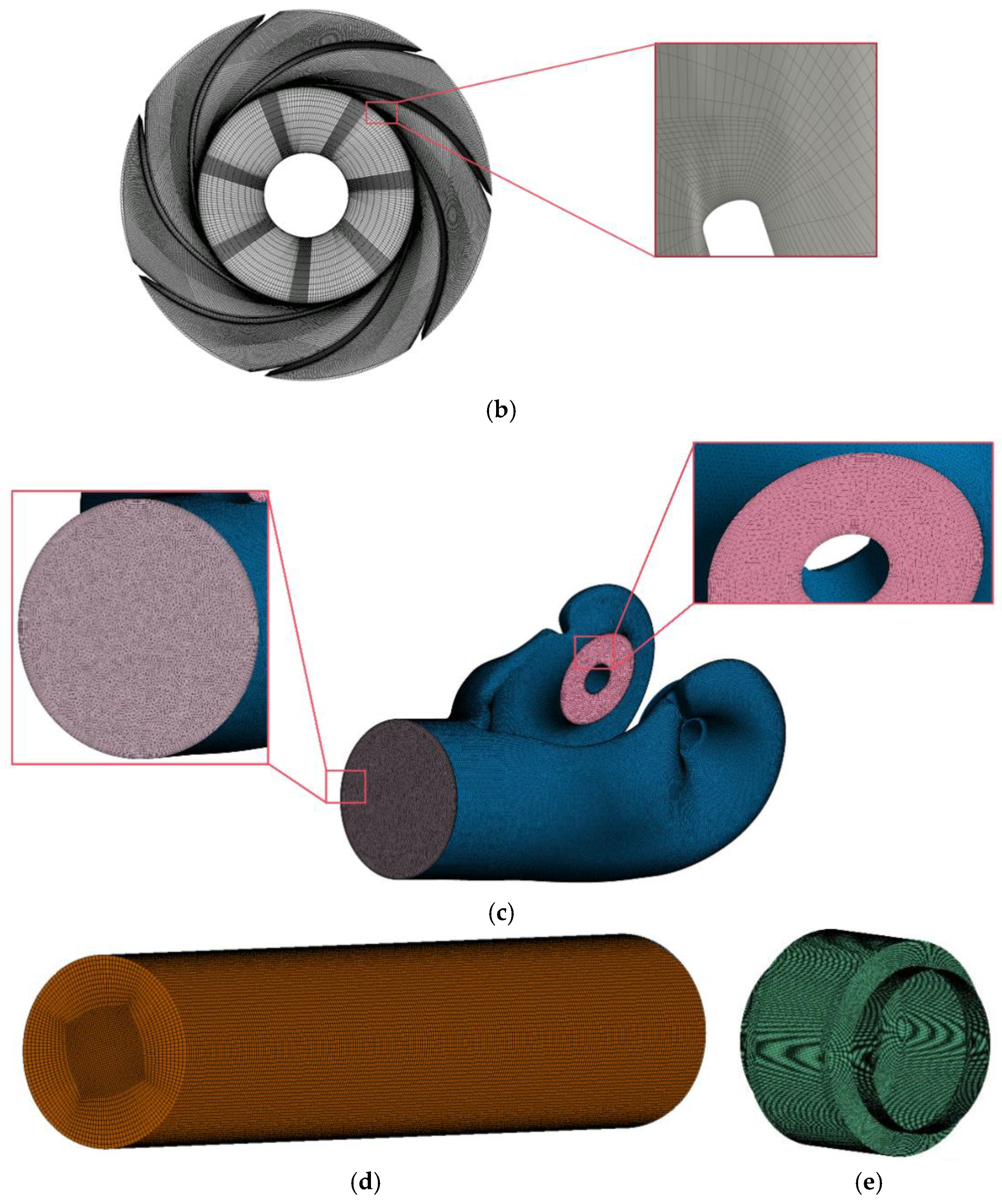
2.3. Grid Independence Verification

To systematically determine the optimal grid resolution balancing computational accuracy and efficiency, a progressive refinement approach was implemented for the double-suction pump’s 3D flow passage model, as illustrated in Figure 4. To accurately capture near-wall flow characteristics, the mesh near wall surfaces of flow components was refined with boundary layer grids. Based on geometric requirements, five inflation layers were generated at an expansion ratio of 1.2. Grid dependency analysis evaluated pump efficiency, head, and shaft power across multiple mesh densities, ultimately selecting 6.43 million elements through convergence verification (Table 3). This methodology ensures computational accuracy while effectively managing resource expenditure. Three prototype configurations underwent grid independence validation under identical block topology structures to eliminate geometric bias. The consistent meshing strategy maintained uniform node distribution parameters across all trimming configurations, mitigating flow comparison distortions from grid artifacts.

2.4. Numerical Simulation

Numerical simulations were performed using the ANSYS CFX 2020 R2, with the SST k-ω turbulence model selected for this study. Compared to the k-ε and Standard k-ω models, the SST k-ω model demonstrates superior capability in capturing complex flow features within centrifugal pumps, exhibiting closer agreement with experimental flow characteristics [17]. The SST k-ω model enhances the standard k-ω formulation by modifying the definition of eddy viscosity to account for the transport of principal turbulent shear stresses. This improvement enables more accurate predictions of adverse pressure gradient flows. The turbulent kinetic energy k and specific dissipation rate ω are governed by Equation (5) and Equation (6), respectively.
( ρ k ) t + ( ρ k u i ) x i = P k β * ρ k ω + x j μ + σ k μ t k x j
( ρ ω ) t + ρ ω μ i z i = α ω k P k β ρ ω 2 + z j μ + σ ω μ t ω x j + 2 1 F 1 ρ σ ω 2 1 ω k x j ω x j
where P k represents the turbulent kinetic energy production term; μ i denotes the turbulent viscosity; α ,   β ,   β ,   σ k ,   σ ω ,   σ ω 2 are model-specific constants; and F1 is the blending function.
Numerical simulations were conducted using ANSYS CFX to analyze the full-flow field characteristics of the prototype pump. The fluid medium was defined as water at 25 °C, with turbulence modeling employing the SST k-ω formulation. Boundary conditions comprised a total pressure inlet (reference pressure: 1 atm) and mass flow outlet. The computational domain was partitioned into rotating (impeller) and stationary (pump chamber, volute, suction chamber) regions, interconnected via interface boundaries. For steady-state simulations, the Frozen Rotor method governed data transfer at rotor–stator interfaces, with solution convergence achieved when RMS residuals reached below 10−6.
Unsteady simulations utilized steady-state results as initial conditions, implementing Transient Frozen Rotor interface treatment with General Grid Interface (GGI) connectivity. The temporal resolution was configured with a 3° impeller rotation per timestep (0.000337838 s), maintaining a maximum of 10 iterations per step. The simulation duration encompassed 14 full impeller revolutions (0.567568 s), preserving the convergence criterion of RMS residuals 10−6.

2.5. Experimental Verification

Experimental verification was conducted on an open test rig at Shandong Shuanglun Co., Ltd. to validate numerical simulation accuracy. The prototype pump was instrumented with identical pressure sensors at both inlet and outlet, while electromagnetic flow sensors measured volumetric flow rates. Critical sensor specifications are detailed in Table 4, with the test bench configuration illustrated in Figure 5.
Figure 6 presents comparative performance curves between numerical simulations and experimental measurements for the prototype pump. Steady-state simulations employed time-averaged results from the final 120 iterations, demonstrating close agreement with test data: maximum relative errors of 1.9% in efficiency and 2.1% in head—both within acceptable 3% thresholds—confirm the computational model’s reliability in capturing internal flow dynamics. Observed discrepancies originate primarily from turbulence model limitations and experimental measurement uncertainties.

3. Results and Discussion

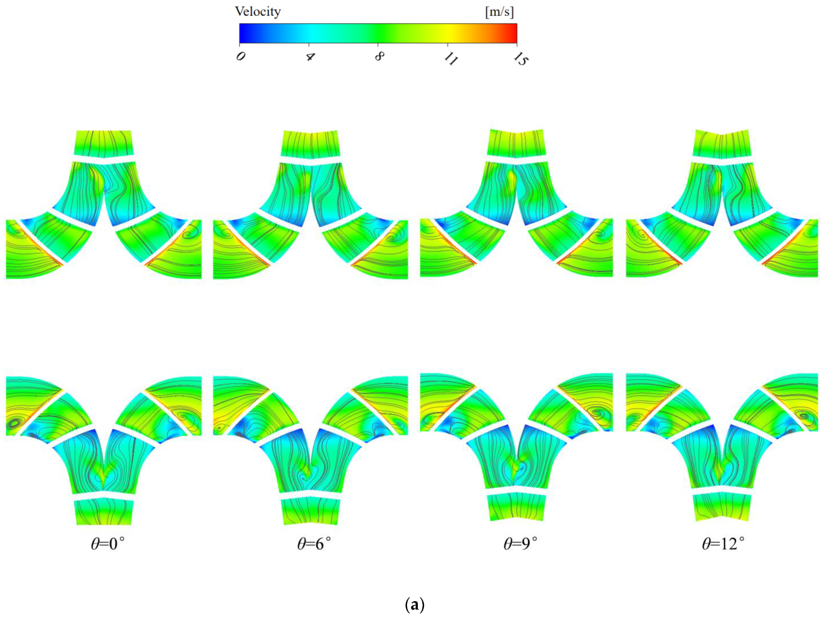
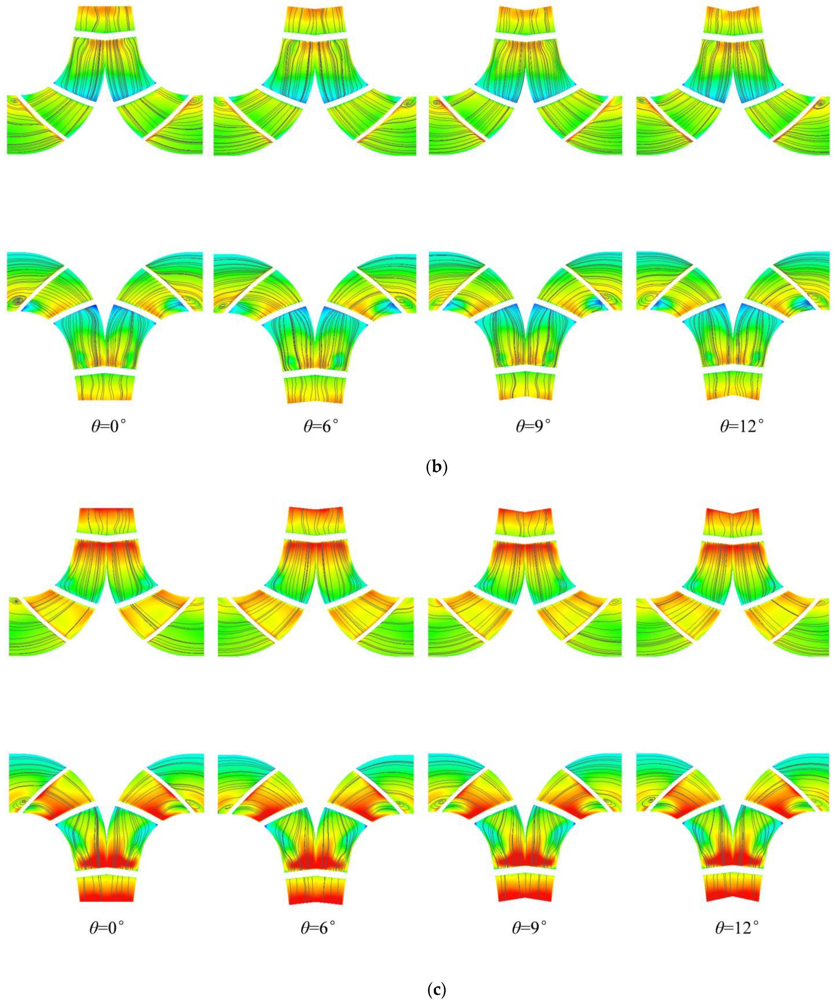
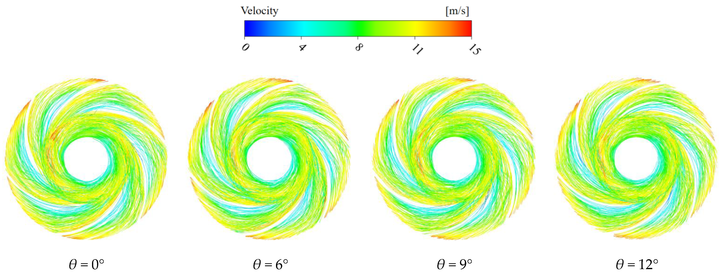
3.1. The Influence of the Impeller Oblique Cutting Angle on the Flow at the Impeller Outlet

In centrifugal pumps, fluid typically flows radially outward from the impeller inlet to outlet. When vortex components emerge in the meridional plane velocity distribution, partial fluid reverses direction against the primary flow, a phenomenon termed flow reversal. The intensity of this reversal reflects flow disorder degree and energy dissipation magnitude. The primary flow rate Q and reversed flow rate Qrev through cross-section S can be calculated using the following equations [18]
Q = S v n d S
Q rev = S v n v n 2 d S
where vn represents the normal-direction velocity component at cross-section S, with flow direction convention defined as positive for outward radial movement (impeller inlet to outlet) and negative for inward flow reversal.
Focusing on the impeller outlet where oblique cutting occurs, this investigation evaluates flow pattern alterations through reversed flow percentage R, calculated using:
R = Q rev Q × 100 %
where Qrev denotes reversed flow rate, and Q represents total through flow.
The influence of impeller oblique cutting angles on outlet reflux ratios and pump efficiency across operational conditions is illustrated in Figure 7. Analysis reveals a consistent decrease in reflux ratios with increasing flow rates for all configurations, peaking at partial-load conditions (0.7Qd) due to reduced axial velocities inducing negative incidence angles at blade inlets. This flow separation mechanism, driven by adverse pressure gradients, generates localized reflux zones at the impeller outlet. At 1.3Qd, diminished pressure gradients suppress reverse flow tendencies, resulting in reduced reflux ratios.
Under partial-load conditions (0.7Qd), reflux ratios exhibit significant positive correlation with cutting angles (θ), while efficiency demonstrates marginal inverse dependence (Δη < 1%). Similar trends emerge at design condition, with reflux ratios increasing and efficiency decreasing slightly as θ enlarges. Conversely, high-flow operation (1.3Qd) shows minimal reflux ratio variation (θ = 12° yielding optimal reduction) and non-monotonic efficiency behavior—minimum at θ = 9° then recovering to peak at θ = 12°.
Comparative evaluation confirms the baseline planar cut (θ = 0°) achieves minimal reflux ratios and maximum efficiency at both partial-load and design conditions. This superiority originates from optimal alignment between blade exit angles and primary flow direction, minimizing flow deviation. Oblique cutting induces progressive flow misalignment, elevating reflux ratios and reducing hydraulic efficiency. Notably, moderate oblique angles (θ = 12°) enhance high-flow performance through improved outlet flow guidance and turbulence mitigation.
To investigate the influence of different oblique cutting angles on the flow field within the impeller, the X-Y cross-section of the impeller, specifically the meridional plane, was constructed as shown in Figure 8. The coordinate origin is located at the geometric center of the impeller, with the inflow direction aligned with the X-axis.
The analysis of the velocity streamlines on the X-Y cross-section for impellers with different oblique cutting angles (Figure 9) clearly reveals significant flow instability characteristics within the impeller. Across the operating range from 0.7Qd to 1.3Qd, the flow velocity in the main flow zone exhibits an increasing trend with rising flow rate for all bevel configurations, reaching its maximum value at the impeller outlet.
Under design condition and high-flow conditions, the flow field distribution for each oblique cutting angles scheme is relatively uniform. Small reflux zones appear near the impeller inlet in all cases. At the design flow rate, the concentration of streamlines slightly intensifies as the oblique cutting angles increases.
Conversely, under low-flow conditions, all four oblique cutting angles schemes exhibit inlet reflux and vortex zones. Some streamlines are densely packed and exhibit significant curvature. Notably, the inlet vortex is more pronounced in the flat-cut impeller. This indicates that beveling the impeller can improve the flow conditions in the inlet region under low-flow operating conditions.

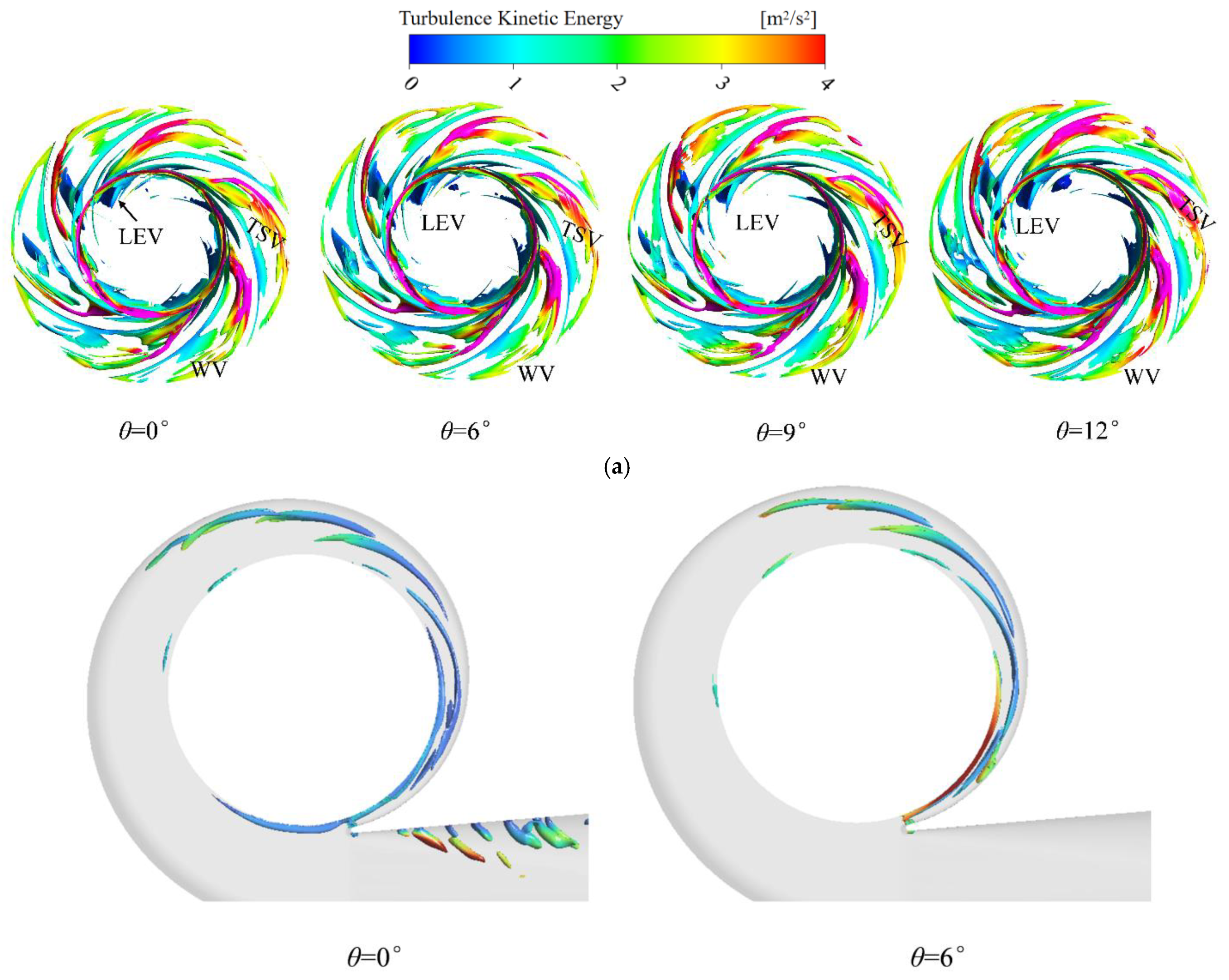
3.2. The Influence of the Impeller Oblique Cutting Angles on the Vortex Structure

A systematic investigation into the impeller oblique cutting angle’s impact on vortex structures in double-suction pumps was conducted using the Ω vortex identification method. This approach enables precise discrimination of rotational motions and concurrent detection of vortices across intensity scales. By implementing a 0.52 threshold [19,20,21], vortices with distinct strength levels were differentiated within the impeller. Spatial-temporal evolution patterns of vortex structures were visualized through turbulent kinetic energy-based color mapping (as shown in Figure 10).
Under design conditions, three characteristic vortex types were consistently observed across four oblique cutting angle configurations: Leading Edge Vortices (LEV) from blade-leading-edge flow separation, Wake Vortices (WV) induced by trailing-edge jet–wake interactions, and Tip Leakage Vortices (TLV) originating from blade–tip boundary layer separation. Progressive increases in oblique cutting angles modified the blade exit angle, redirecting fluid flow paths. This redirection amplified suction-side low-pressure zones near trailing edges, driving sequential expansion of WV, LEV, and TLV regions. The spatial growth of these vortices correlated with elevated energy dissipation via intensified turbulent interactions. Three-dimensional streamline visualizations depict vortex structure distributions within the impeller, as presented in Figure 11. Progressive extension of low-velocity zones toward the blade leading edge regions is observed with increasing oblique cutting angles, while simultaneously intensified flow disorder emerges near the suction surface trailing edge. This progressive flow variation directly visualizes alterations in impeller–internal vortex dynamics.
Volute analysis identified transient vortices in the diffuser section, signaling flow instabilities. While vortex density increased with larger oblique cutting angles, a critical transition occurred at 6°: diffuser vortices vanished abruptly, coinciding with amplified turbulent kinetic energy at the volute inlet. This phenomenon suggests a threshold-dependent shift in energy transfer mechanisms, where classical vortex dissipation pathways are supplanted by alternative loss modes.

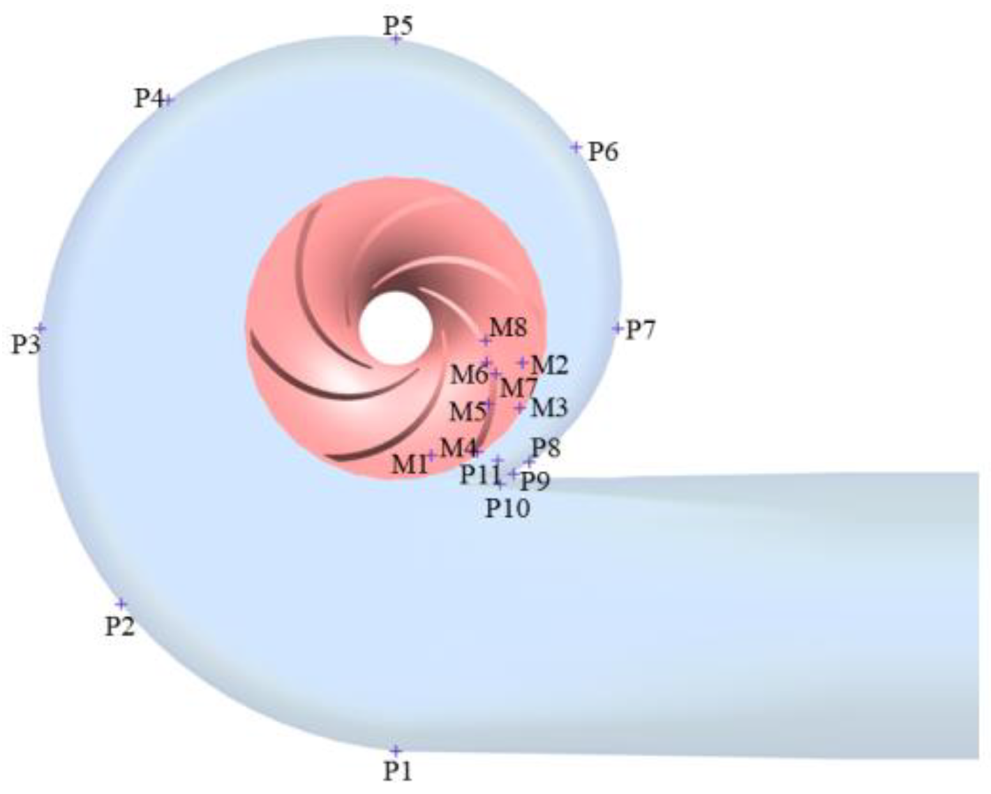
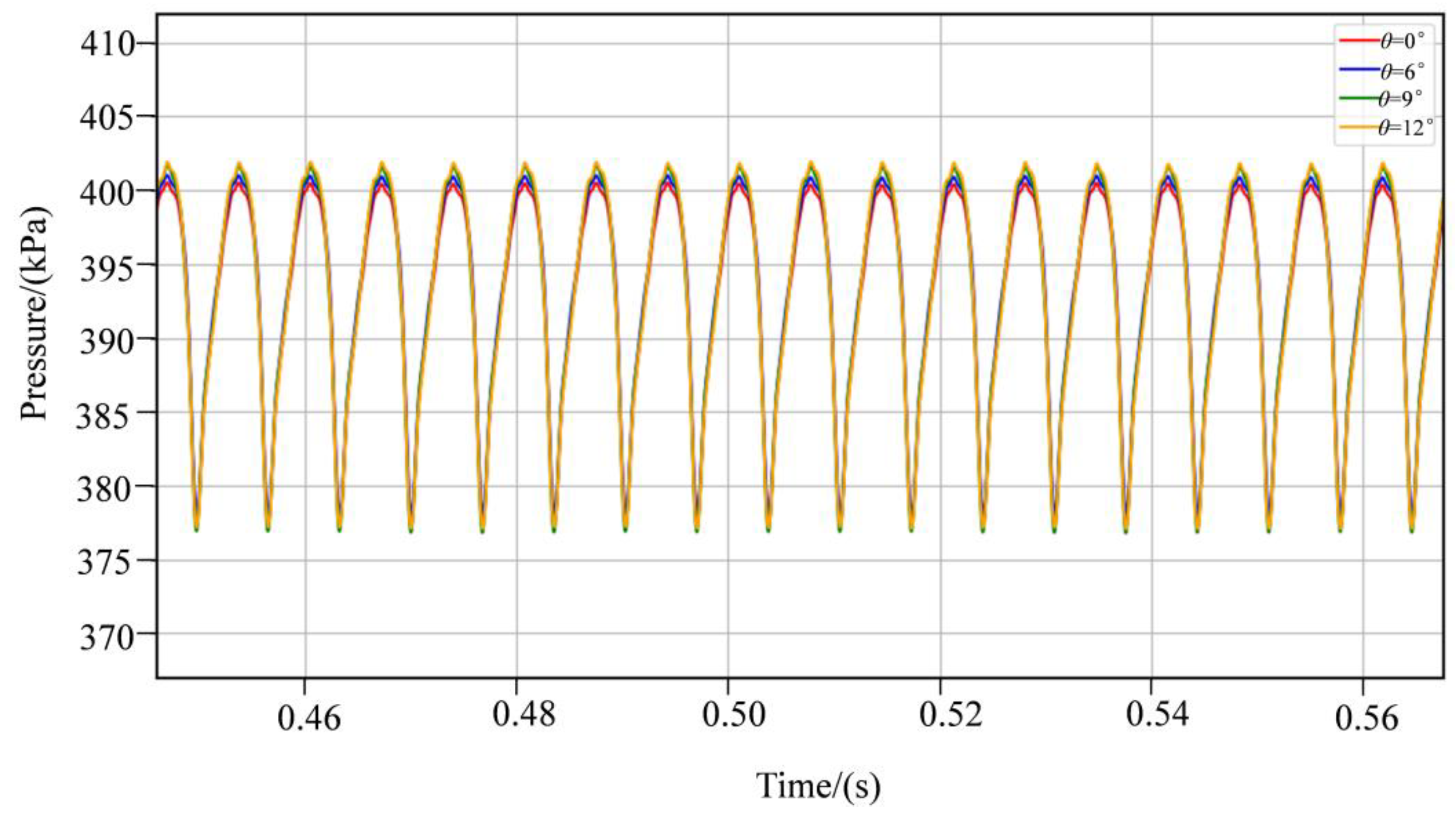
3.3. The Influence of the Impeller Oblique Cutting Angle on Pressure Pulsation

To investigate the transient pressure field characteristics induced by impeller oblique cutting in double-suction pumps, systematically positioned pressure pulsation monitoring points were implemented within the flow domain, as illustrated in Figure 12. Eight monitoring points (P1–P8) were uniformly distributed along the volute casing at 45° intervals, while three monitoring points (P9–P11) were concentrated near the volute tongue to capture flow separation characteristics. Additional monitoring points were positioned within the impeller flow channels (M1–M2), pump cavities (M3–M4), blade pressure surfaces (M7–M8), and blade suction surfaces (M5–M6).
As shown in Figure 13, pressure variations at monitoring point P11 exhibited periodic behavior across three rotational cycles for all oblique cutting angle configurations, with 18 peaks and 18 troughs corresponding to the impeller’s six blades. This confirms the blade-induced periodic modulation of pressure fluctuations near the volute tongue. Pressure fluctuation amplitudes for the 9° and 12° bevel configurations exceeded those of the flat-cut and 6° oblique cutting. Collectively, these results demonstrate that flat-cut or smaller oblique cutting angles reduce static-rotor interaction intensity and subsequently suppress pulsation amplitudes at the volute tongue.
Frequency–domain analysis of pressure data (Figure 14) under design conditions revealed dominant spectral peaks at fBPF for monitoring points P3, P6, P8, and P11, indicating blade-passing effects as the primary excitation source. At monitoring points P3, the 9° oblique cutting configuration exhibited the lowest amplitude at fBPF but higher amplitude at fn compared to other configurations, suggesting a trade-off between frequency components during blade-edge modification. Monitoring points P8 and P11 near the volute tongue displayed pronounced harmonic frequencies and periodic fluctuations, reflecting strong static–rotor interaction. Notably, the flat-cut impeller generated weaker fBPF amplitudes at P11 compared to oblique cutting configurations, indicating suppressed wake vortices formation and reduced flow instability.
These results demonstrate that oblique cutting angle selection significantly affects both blade-passing frequency (fBPF) and shaft frequency (fn) pressure fluctuations. The flat-cut impeller exhibited superior performance in mitigating wake vortices and static–rotor interaction, providing critical insights for optimizing impeller trimming strategies in double-suction pumps.

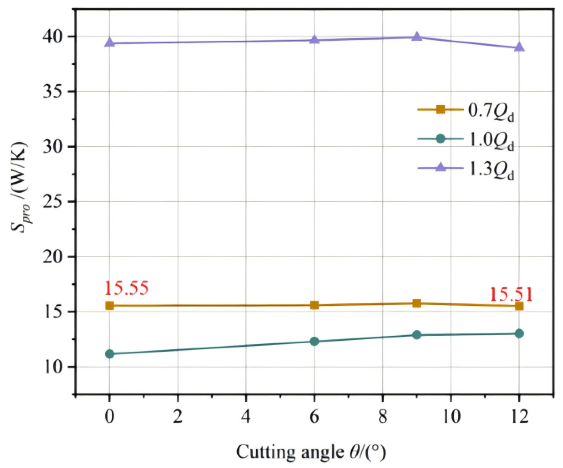
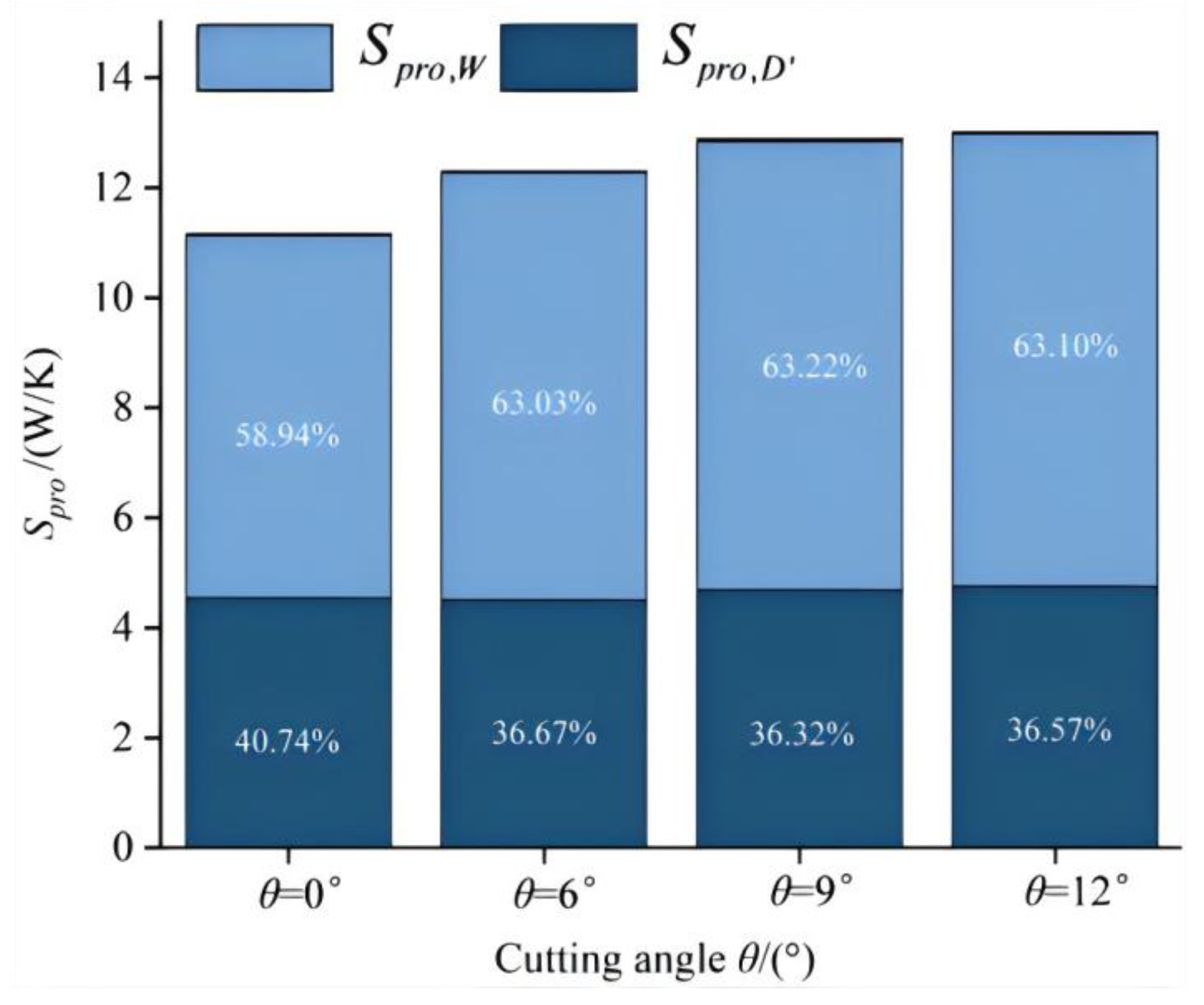
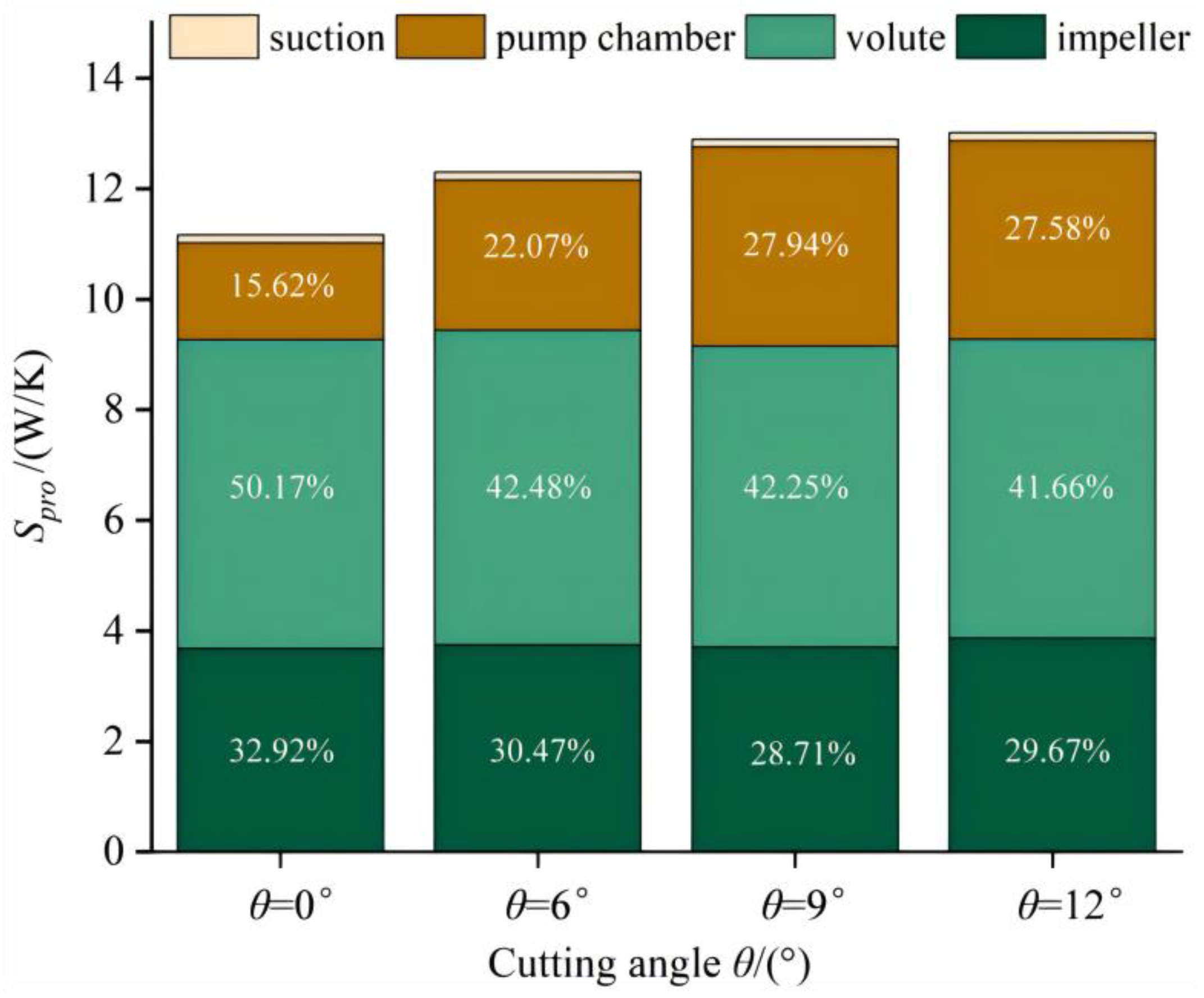
3.4. The Influence of the Impeller Oblique Cutting Angles on Energy Loss

According to the second law of thermodynamics, for any irreversible process, its entropy will always increase. Under the operating conditions of the double suction pump, the mechanical energy of the impeller is converted into the kinetic energy of the fluid. During this energy conversion process, due to the existence of viscous stress, Reynolds stress, and turbulence in the fluid during operation, an irreversible conversion process from mechanical energy to internal energy is inevitably triggered, which is manifested as an increase in the entropy value of the system, that is, the entropy generation phenomenon. Therefore, the entropy generation theory can be applied to numerical simulation to evaluate the energy loss of double-suction pumps.
In the turbulent flow of a single-phase incompressible ideal fluid, the entropy transport equation can be expressed as
ρ s t + u s x + v s y + w s z = div q T + Φ T + Φ Θ T 2
where ρ represents the fluid density, s represents the specific entropy parameter, the velocity field is composed of Cartesian components u, v, and w, and T characterizes the thermodynamic temperature. The right side of the equation contains three key terms: reversible heat exchange term div q T , viscous dissipation entropy generation term Φ T , and heat transfer temperature difference entropy generation term Φ Θ T 2 .
According to the Reynolds mean theory, the flow variable is decomposed into the sum of the time-mean quantity and the pulsation quantity. The entropy transport control equation obtained through the Reynolds mean operation can be expressed as
ρ s ¯ t + u ¯ s ¯ x + v ¯ s ¯ y + w ¯ s ¯ z = div q T ¯ ρ u s x ¯ + v s y ¯ + w s z ¯ + Φ ¯ T + Φ Θ ¯ T 2
where div q T ¯ ρ u s x ¯ + v s y ¯ + w s z ¯ represents the reversible heat transfer amount. The internal flow of hydraulic machinery is an approximately adiabatic process, and the entropy production rate Φ Θ ¯ T 2 due to the increase in the heat transfer temperature difference can be ignored. Therefore, the entropy production rate Φ ¯ T due to the increase in dissipation can be directly obtained.
Φ ¯ T = S ˙ D ¯ + S ˙ D
where S ˙ D ¯ is the entropy production rate caused by the average velocity, usually used to represent direct dissipation, and S ˙ D is the entropy production rate caused by the pulsating velocity, usually used to represent turbulent dissipation [22,23].
S ˙ D ¯ = μ e f f T ¯ 2 u ¯ x 2 + v ¯ y 2 + w ¯ z 2 + u ¯ y + v ¯ x 2 + u ¯ z + w ¯ x 2 + v ¯ z + w ¯ y 2
S ˙ D = μ T ¯ 2 u x 2 ¯ + v y 2 ¯ + w z 2 ¯ + u y + v x 2 ¯ + u z + w x 2 ¯ + v z + w y 2 ¯
μ e f f = μ + μ t
where μ is dynamic viscosity, μ e f f is effective dynamic viscosity, and μ t is turbulent dynamic viscosity.
It is known that speed and temperature can be used to determine S ˙ D ¯ , while S ˙ D cannot be solved directly. When the SST k-ω turbulence model is selected, S ˙ D can be expressed as
S ˙ D = α ρ ω k T
where α = 0.09 , and ω and k are the turbulent vortex frequency and turbulence intensity, respectively. Integrating the local entropy production rate of the calculation domain can obtain the entropy production caused by the time-average velocity and the pulsating velocity [24,25], and the formula is as follows:
S p r o , D ¯ = V S ˙ D ¯ d V
S p r o , D = V S ˙ D d V
In addition, the velocity gradient and pressure gradient on the surface of the centrifugal pump blade are relatively high, and there is a strong wall effect in the flow field. The entropy generated by the wall effect cannot be ignored, and its calculation formula is
S p r o , W = A τ v T d A
where τ represents the shear stress of the wall surface, and v represents the velocity at the first layer grid near the wall surface.
To sum up, the total entropy production within the calculation domain is
S p r o = S p r o , D ¯ + S p r o , D + S p r o , W
Figure 15 shows the influence law of the model pump at different oblique cutting angles under different working conditions on the total entropy production. It can be seen from the figure that with the increase in flow rate, the total entropy production of each oblique cutting scheme shows a trend of first decreasing and then increasing. Meanwhile, under both the low-flow condition and the design condition, the total entropy production increases slowly with the increase in the angle, but its increase rate shows a nonlinear relationship with the oblique cutting angles of the impeller. Under the working condition of high flow rate, with the increase in the cutting angle, the total entropy production in the pump shows a change characteristic of first slightly increasing and then significantly decreasing. Especially when the impeller is beveled by 12°, the total entropy production decreases significantly, indicating that under the working condition of high flow rate, adopting a larger impeller oblique cutting angles can effectively reduce the total entropy production of the double-suction pump. Therefore, in the optimal design of double-suction pumps, the reasonable selection of the impeller oblique cutting angles is one of the key parameters for the performance of the lift pump.
To further analyze the relationship between the impeller oblique cutting angle and the entropy output of each type, Figure 16 compares the variations in the impeller oblique cutting angle on the entropy production of the three types under the design conditions of the model pump. Since the direct dissipation proportion of each scheme is approximately 0.31% to 0.46%, always less than 0.3%, the wall dissipation caused by the wall effect and the turbulent dissipation caused by the pulsating velocity are analyzed with emphasis. As can be seen from the figure, in all four beveling schemes, wall dissipation dominates, accounting for approximately 58.94% to 63.10% of the total entropy production. Therefore, when calculating the influence of impeller beveling on the energy loss of the double-suction pump, the impact of the avoidance effect on energy loss cannot be ignored, and wall loss must be taken into account. With the increase in the slant angle, the turbulent dissipation loss slightly increases, but the change is not obvious. Meanwhile, with the increase in the slant angle, the wall dissipation of each slant scheme gradually increases. This indicates that for this model pump, the increase in the slant angle will intensify the wall effect, resulting in more energy loss. Figure 17 shows the influence law of the total entropy generation of each flow component of the model pump when the impeller is beveled at different angles at the designed flow rate. From the analysis of the diagram, it can be seen that the entropy loss of each flow-through component is in the order of volute, impeller, pump chamber, and suction chamber. The volute has always been the main flow-through component for the total entropy generation of each model, with its proportion ranging from 41.66% to 50.17%. However, the entropy generation contribution of the suction chamber is the smallest, with its proportion always less than 5%, and it is less affected by the change in the impeller oblique cutting angle. Under the design working conditions, as the oblique cutting angle increases, the total entropy production in the pump shows a continuous upward trend. Among them, the loss in the pump cavity increases most significantly, and its increase rate is basically consistent with the growth rate of the total entropy production. When the impeller is horizontally cut, the total entropy production reaches the minimum value of 11.16 W/K. For the model pump, the beveling of the impeller has the greatest impact on the entropy loss in the pump cavity, and its proportion increases from 15.62% to 27.58%. This indicates that an increase in the beveling angle of the impeller may cause the velocity distribution of the fluid at the blade outlet to tend to be uneven, and increase the complexity of the fluid passing through the transition area between the blade and the pump cavity. Uneven velocity distribution and complex geometric shape changes are prone to causing turbulence, especially inside the pump cavity. The formation of turbulence will lead to a large amount of kinetic energy being converted into thermal energy, thereby increasing energy loss.
From the above analysis, it is clear that different angles of the impeller’s oblique cutting have the greatest impact on entropy loss in the pump cavity. In order to further analyze the energy loss in the transition zone between the impeller and the pump cavity caused by the impeller’s oblique cutting angle, a visual analysis of the losses at the impeller and the pump cavity is conducted. It can be seen from Figure 18 that the entropy generation is mainly concentrated on the suction surface of the blade and the junction area between the impeller outlet and the pump cavity. In the case of a flat cut of the impeller, the energy loss caused by reflux on the suction surface of the blade is relatively large. As the angle increases to 6°, the loss at the suction surface of the blade slightly decreases. As the angle increases, the range of the high-entropy production area in the pump cavity gradually expands, indicating that the entropy production loss in the pump cavity also increases accordingly. Simultaneously, combined with the vortex structure distribution above, it can be found that the high entropy generation region also corresponds to the high turbulent kinetic energy region. This spatial correspondence further substantiates that vortex formation inherently induces quantifiable entropy production.

4. Conclusions

This study focused on a double-suction centrifugal pump. Under the condition of ensuring the same average outer diameter, the influence of different oblique cutting angles (0°, 6°, 9°, 12°) on the flow characteristics inside the pump was systematically compared through a combination of numerical simulation and experiments. The specific conclusions obtained are as follows:
(1)
When the impeller is cut horizontally under low-flow conditions and design conditions, the direction of the blade outlet is consistent with the main flow direction, and the fluid can flow out of the impeller at the optimal angle. As the oblique cutting angles increases, the flow at the blade outlet begins to deviate from the ideal direction, resulting in an increase in the reflux ratio and a decrease in efficiency. Under the working condition of high flow rate, the reflux ratio at the impeller outlet slightly decreases with the increase in the oblique cutting angles. It is the smallest when the impeller is bevel at 12°, and the efficiency is also the largest when it is bevel at 12°. This indicates that under this working condition, bevel at a certain angle can improve the outlet situation at the impeller outlet and enhance the fluidity of the fluid.
(2)
At monitoring point P11 in the volute tongue area, the amplitude of pressure pulsation is the largest, showing a distinct feature dominated by blade frequency. Moreover, the pulsation period corresponds to the number of blades. The amplitudes of pressure pulsation in the 9° and 12° oblique cutting schemes are significantly higher than those in the flat cutting and 6° oblique cutting schemes. The selection of the oblique cutting angles not only affects the intensity of the blade frequency, but also has a significant impact on the pressure pulsation at the shaft frequency. However, for the flat cutting of the impeller of this double-suction pump, it shows obvious advantages in suppressing the formation of the wake vortices and reducing the static–rotor interaction. These findings provide an important reference basis for the optimization of the impeller cutting of the double-suction pump.
(3)
This double-suction pump mainly relies on wall dissipation. An increase in the oblique cutting angles will intensify the wall effect, leading to an increase in energy loss and an increase in total entropy production. The volute is always the component with the maximum entropy generation, accounting for 41.66% to 50.71%. The bevel cutting of the impeller has the greatest impact on the pump cavity loss. Under the design conditions, the total entropy generation of the flat cutting scheme is the lowest. The bevel cutting will increase the non-uniformity of the impeller outlet velocity and intensify the turbulence loss in the pump cavity.
(4)
While the current study employs the SST k-ω turbulence model, future work could implement high-fidelity approaches such as Large Eddy Simulation (LES) or Detached Eddy Simulation (DES). These advanced methodologies would enhance the resolution of complex turbulent structures and transient flow characteristics induced by impeller beveling, particularly improving prediction accuracy for oblique cutting-modified wake vortices and static–rotor interaction effects.
(5)
Given that pumps predominantly operate at the design point, this study prioritizes the design operating condition while maintaining invariant key geometric parameters such as blade count. Future investigations could examine the post-beveling performance of double-suction pumps across varying specific speeds and blade counts.

Author Contributions

Conceptualization, W.W.; Methodology, Z.W.; Validation, J.L.; Formal analysis, J.P.; Investigation, X.L.; Data curation, H.W.; Visualization, K.W. All authors have read and agreed to the published version of the manuscript.

Funding

The study was supported by the National Natural Science Foundation of China (Grant No. 52209112) and the National Key Research and Development Program of China (Grant No. 2022YFC3202901).

Data Availability Statement

All the data in this paper are obtained by physical experiment and numerical simulation, and the data used to support the findings of this study are available from the corresponding author upon request.

Conflicts of Interest

Authors Zhongsheng Wang and Jun Liu were employed by the company Shandong Shuanglun Co., Ltd. The remaining authors declare that the research was conducted in the absence of any commercial or financial relationships that could be construed as a potential conflict of interest.

References

  1. Miao, S.; Tan, X.; Luo, W.; Wang, X.; Yang, J. The mechanism of internal energy losses in double-suction centrifugal pumps under direct and reverse conditions. Energy 2024, 306, 132547. [Google Scholar] [CrossRef]
  2. Qu, X.; Wang, L. Effects of impeller trimming methods on performances of centrifugal pump. J. Energy Eng. 2016, 142, 04016008. [Google Scholar] [CrossRef]
  3. Shadab, M.; Karimipour, M.; Najafi, A.F.; Paydar, R.; Nourbakhsh, S.A. Effect of impeller shroud trimming on the hydraulic performance of centrifugal pumps with low and medium specific speeds. Eng. Appl. Comput. Fluid Mech. 2022, 16, 514–535. [Google Scholar] [CrossRef]
  4. Khalifa, A.E. Performance and vibration of a double volute centrifugal pump: Effect of impeller trimming. In ASME International Mechanical Engineering Congress and Exposition; American Society of Mechanical Engineers: New York, NY, USA, 2014; Volume 46476, p. V04AT04A063. [Google Scholar] [CrossRef]
  5. Gonzalez, J.; Parrondo, J.; Santolaria, C.; Blanco, E. Steady and unsteady radial forces for a centrifugal pump with impeller to tongue gap variation. J. Fluids Eng. 2006, 128, 454–462. [Google Scholar] [CrossRef]
  6. Šavar, M.; Kozmar, H.; Sutlović, I. Improving centrifugal pump efficiency by impeller trimming. Desalination 2009, 249, 654–659. [Google Scholar] [CrossRef]
  7. Qiu, G.; Zhu, S.; Wang, K.; Wang, W.; Hu, J.; Hu, Y.; Zhi, X.; Qiu, L. Numerical study on the dynamic process of reciprocating liquid hydrogen pumps for hydrogen refueling stations. Energy 2023, 281, 128303. [Google Scholar] [CrossRef]
  8. Wang, K.; Zhang, Z.; Jiang, L.; Liu, H.; Li, Y. Effects of impeller trim on performance of two-stage self-priming centrifugal pump. Mech. Eng. 2017, 9, 1687814017692493. [Google Scholar] [CrossRef]
  9. Han, Y.; Li, H.; Tiganik, T.; Wang, Y.; Zhou, L. Influence mechanism of trimming impeller diameter in a centrifugal pump by computational fluid dynamics investigation. J. Fluids Eng. 2023, 145, 021205. [Google Scholar] [CrossRef]
  10. Jain, S.V.; Swarnkar, A.; Motwani, K.H.; Patel, R.N. Effects of impeller diameter and rotational speed on performance of pump running in turbine mode. Energy Convers. Manag. 2015, 89, 808–824. [Google Scholar] [CrossRef]
  11. Huang, B.; Zeng, G.; Qian, B.; Wu, P.; Shi, P.; Qian, D. Pressure fluctuation reduction of a centrifugal pump by blade trailing edge modification. Processes 2021, 9, 1408. [Google Scholar] [CrossRef]
  12. Shi, W.D.; Zhou, L.; Lu, W.G.; Li, H. Numerical simulation and experimental study on deep-well centrifugal pump with small rear shroud diameter. Mater. Res. 2012, 354, 659–663. [Google Scholar] [CrossRef]
  13. Xu, Z.; Zhang, F.; Zhu, L.; Chen, K.; Zhang, J.; Hong, Q. Effects of impeller Trimming on energy performance and fluid-structure interaction characteristics of the two-stage pump. Energy 2025, 317, 134698. [Google Scholar] [CrossRef]
  14. Ye, W.; Zhuang, B.; Wei, Y.; Luo, X.; Wang, H. Investigation on the unstable flow characteristic and its alleviation methods by modifying the impeller blade tailing edge in a centrifugal pump. J. Energy Storage 2024, 86, 111358. [Google Scholar] [CrossRef]
  15. Stepanoff, A.J. Centrifugal and Axial Flow Pumps: Theory, Design, and Application; ASCE: Reston, VA, USA, 1991. [Google Scholar]
  16. Yates, M.A.; Weybourne, I. Improving the energy efficiency of pumping systems. J. Water Supply Res. Technol. AQUA 2001, 50, 101–111. [Google Scholar] [CrossRef]
  17. Ramadhan Al-Obaidi, A. Effects of different turbulence models on three-dimensional unsteady cavitating flows in the centrifugal pump and performance prediction. Int. J. Nonlinear Sci. Numer. Simul. 2019, 20, 487–509. [Google Scholar] [CrossRef]
  18. Wang, K.; Ju, Y.; Zhang, C. A quantitative evaluation method for impeller-volute tongue interaction and application to squirrel cage fan with bionic volute tongue. J. Fluids Eng. 2019, 141, 081104. [Google Scholar] [CrossRef]
  19. Tian, S.; Gao, Y.; Dong, X.; Liu, C. Definitions of vortex vector and vortex. J. Fluid Mech. 2018, 849, 312–339. [Google Scholar] [CrossRef]
  20. Zhang, F.; Appiah, D.; Chen, K.; Yuan, S.; Adu-Poku, K.A.; Wang, Y. Dynamic characterization of vortex structures and their evolution mechanisms in a side channel pump. J. Fluids Eng. 2020, 142, 111502. [Google Scholar] [CrossRef]
  21. Tran, C.T.; Long, X.; Ji, B. Vortical structures in the cavitating flow in the Francis-99 draft tube cone under off-design conditions with the new omega vortex identification method. J. Phys. 2019, 1296, 012011. [Google Scholar] [CrossRef]
  22. Kock, F.; Herwig, H. Local entropy production in turbulent shear flows: A high-Reynolds number model with wall functions. Int. J. Heat Mass Transf. 2004, 47, 2205–2215. [Google Scholar] [CrossRef]
  23. Kock, F.; Herwig, H. Entropy production calculation for turbulent shear flows and their implementation in CFD codes. Int. J. Heat Fluid Flow 2005, 26, 672–680. [Google Scholar] [CrossRef]
  24. Herwig, H.; Kock, F. Direct and indirect methods of calculating entropy generation rates in turbulent convective heat transfer problems. Heat Mass Transf. 2007, 43, 207–215. [Google Scholar] [CrossRef]
  25. Herwig, H.; Kock, F. Local entropy production in turbulent shear flows: A tool for evaluating heat transfer performance. J. Therm. Sci. 2006, 15, 159–167. [Google Scholar] [CrossRef]
Figure 1. The flowchart of the research.
Energies 18 03907 g001
Figure 2. Schematic diagram of the structure of a double-suction pump.
Energies 18 03907 g002
Figure 3. Schematic diagram of impeller cutting.
Energies 18 03907 g003
Figure 4. Schematic diagram of the grid of each component. (a) Mesh of volute. (b) Mesh of impeller. (c) Mesh of suction chamber. (d) Mesh of outlet pipe. (e) Mesh of pump chamber.
Energies 18 03907 g004aEnergies 18 03907 g004b
Figure 5. Layout of the test rig.
Energies 18 03907 g005
Figure 6. Comparison of external characteristic curves between the simulated and experimental.
Energies 18 03907 g006
Figure 7. Comparison of reflux ratio at the impeller outlet and efficiency with different oblique cutting angles under various working conditions.
Energies 18 03907 g007
Figure 8. The X-Y cross-section position of the impeller.
Energies 18 03907 g008
Figure 9. The velocity streamline distribution on the X-Y cross-section of the impeller with different oblique cutting angles under various working conditions. (a) 0.7Qd. (b) 1.0Qd. (c) 1.3Qd.
Energies 18 03907 g009aEnergies 18 03907 g009b
Figure 10. Comparison of vortex structures distributions of impeller and volute with different oblique cutting angles. (a) Impeller. (b) Volute.
Energies 18 03907 g010aEnergies 18 03907 g010b
Figure 11. Comparison of 3D velocity streamline distribution of impeller with different oblique cutting angles.
Energies 18 03907 g011
Figure 12. Distribution of pressure monitoring points.
Energies 18 03907 g012
Figure 13. Time-domain pressure pulsation at monitoring point P11 under different operating conditions with varying oblique cutting angles.
Energies 18 03907 g013
Figure 14. The frequency domain diagram of pressure pulsation at each monitoring point with different angles of impeller oblique cutting.
Energies 18 03907 g014
Figure 15. The influence law of the pump being beveled at different angles under different working conditions on the total entropy production.
Energies 18 03907 g015
Figure 16. Comparison of entropy production of various types at different oblique cutting angles under the design working conditions.
Energies 18 03907 g016
Figure 17. Comparison of entropy production of each flow component at different oblique cutting angles under the design working conditions.
Energies 18 03907 g017
Figure 18. The entropy production rate distribution of impellers at various oblique cutting angles and the cross-section of the pump cavity.
Energies 18 03907 g018
Table 1. Main structural parameters.
ParametersValue
Specific speed ns90
Impeller suction diameter D1/(mm)192
Impeller outlet diameter D2/(mm)365
Impeller inlet install angle β1/(°)20.8
Impeller outlet install angle β2/(°)29.6
Impeller outlet width b2/(mm)46
Number of blades Z6
Rotational speed n/(r/min)1480
Volute inlet width b3/(mm)100
Table 2. Specific speed and allowable cutting allowance.
ns60120200300500
φD0.20.150.110.090.07
Table 3. Verification results of grid independence.
Specific SpeedNumber of Meshes/×106Efficiency/%
ns = 902.2883.31
5.5485.66
6.4385.87
7.8685.87
8.2185.88
Table 4. Main parameters of the sensors.
ParameterSensor TypeMeasurement AccuracyRange
Flow rateElectromagnetic flow transducer±0.3%0–1000 m3/h
PressureEJA530E Pressure sensor±0.1%0–1 MPa
Disclaimer/Publisher’s Note: The statements, opinions and data contained in all publications are solely those of the individual author(s) and contributor(s) and not of MDPI and/or the editor(s). MDPI and/or the editor(s) disclaim responsibility for any injury to people or property resulting from any ideas, methods, instructions or products referred to in the content.

