1. Introduction
The fourth generation of AC/DC converters has introduced significant advancements, providing new opportunities for reliable and efficient operation of microgrids. This generation of converters enables the independent control of the current in each phase of the AC/DC inverter, addressing many challenges associated with microgrid asymmetry [
1]. This functionality is achieved through two fundamental modifications to the classical three-phase three-wire control system. The first improvement involves extending the topology by incorporating an additional passive or active leg and effectively introducing a fourth wire into the system [
2,
3]. The choice between a passive or active solution depends on application-specific requirements, including the level of current asymmetry and the desired power output of the converter [
4]. The second enhancement involves transforming the traditional three-phase vector control [
5] into three independent single-phase control algorithms [
6]. Alternatively, vector control combined with symmetrical component decomposition can be utilized to manage the current components independently [
7]. These innovations facilitate voltage symmetrization in microgrids by enabling the injection of independently controlled phase currents through an AC/DC four-wire converter [
8]. For example, in [
9], the theoretical foundations for compensating unbalanced power in four-wire networks were established, focusing on decomposing to symmetrical power components. In [
10], the authors proposed a triple-loop control strategy to address voltage unbalance in four-wire inverters with split capacitors, achieving reliable voltage stabilization under asymmetrical loading. Although this approach mitigates voltage asymmetry within the microgrid, it simultaneously transfers the asymmetry problem to the DC link of the AC/DC converter [
11,
12]. The asymmetrical injection or withdrawal of currents introduces additional challenges in managing the DC link, necessitating further technical solutions to address the resulting issues.
When asymmetry is introduced in the system, such as when one phase draws energy from the grid while the other two deliver energy, the sum of the time-variant components no longer equals zero [
13,
14]. This imbalance causes power pulsations to appear in the DC link. The presence of a high AC component in the DC link is particularly undesirable, as it leads to increased losses in the balancing module, thereby reducing the overall efficiency and reliability of the system [
15,
16]. These challenges underscore the importance of developing effective solutions to mitigate the adverse effects of asymmetry on DC-link performance.
The study presented in [
14] introduced a method for canceling pulsations in a DC-link by directly measuring the pulsation current. This approach, which leverages a resonant algorithm, is fast and accurate. However, this solution increases the inductance between the energy storage and the DC link of the power converter, leading to higher costs. In addition, it requires an ADC measurement channel and an AC and DC transducer, which adds complexity to the system.
In [
17], an optimized phase-shift modulation strategy was introduced to reduce harmonic stress on the DC-link capacitor in cascaded converters. By adjusting the carrier phase shift between modulated signals, DC-link current distortion was minimized, improving efficiency and capacitor lifespan. However, precise phase synchronization is required, adding control complexity.
An adaptive active capacitor converter was proposed in [
18] to enhance the stability of cascaded DC power-supply systems. Pulsations in the DC link were reduced using a nonisolated DC/DC converter. This solution is particularly effective in applications with unstable DC-link voltages. For systems in which electrochemical energy storage is directly connected to the DC link, voltage pulsations are inherently compensated for by the energy storage current. However, the high AC component of the current periodically charges and discharges energy, leading to increased energy losses and potentially reducing the lifespan of the storage system [
13]. These limitations highlight the need for further optimization to mitigate DC-link pulsations.
Recent studies have also explored the performance of various four-leg inverter topologies under unbalanced load conditions. Study [
19] conducted a comparative analysis of two-level and three-level inverters employing model predictive control (MPC), demonstrating that the three-level four-leg inverter topology offers superior performance in terms of current total harmonic distortion (THD), leakage current, and DC-link voltage stability, especially in applications requiring asymmetrical operation such as wave energy converters. These findings underline the importance of inverter design choices in managing asymmetry and maintaining energy quality.
To overcome this problem, in this study, researchers proposed a novel solution based on shifting the pulsation problem from a DC link to a supercapacitor. The key innovation lies in the sensorless current pulsation calculation algorithm, which requires only the measurement of voltages and currents on the AC side, which are already essential for the operation of the inverter. This significantly simplifies the overall system by eliminating the requirement for additional sensors or measurement channels dedicated to the DC link. Moreover, the algorithm incorporates an SOGI filter in its structure, allowing for the precise and rapid determination of the pulsation current on the DC bus, which further enhances its effectiveness. The proposed approach, implemented using a bidirectional DC/DC buck–boost converter, not only enhances the reliability of the power converter but also reduces the system complexity and cost.
This article is organized into several sections to present the proposed solution and its validation.
Section 2 describes the methodology for calculating DC-link pulsations in an AC/DC converter.
Section 3 introduces the system topology and the laboratory test bench used for validation.
Section 4 and
Section 5 presents the experimental results, followed by a discussion of the findings and the main conclusions. This structured format ensured clarity and facilitated the application of the proposed solution in technical practice.
2. Materials and Methods
The main components of the AC–DC four-wire converter are the current and voltage sensors placed in each phase. These sensors enable the calculation of the instantaneous AC and DC components of the DC-link current based on three-phase instantaneous currents and the grid voltage synchronization angle. This capability is crucial for analyzing the behavior of the DC-link current, particularly under asymmetrical operating conditions, where current imbalances in the network can introduce fluctuations in the DC link. The behavior of the DC-link current in an AC/DC converter under such asymmetrical conditions can be mathematically described. The magnitude of the AC component of the DC-link current
as a function of the magnitude of the AC component of the neutral wire current
can be expressed as follows:
where
Va,b,c is the phase RMS voltage, and
VDC is the DC-link voltage.
The instantaneous value of the AC component can be further described as
where
is the phase of neutral wire current.
If the efficiency of the inverter is neglected, Equation (1) can be used to approximate the power output in the DC link [
14]. When the inverter operates with symmetric currents, the sum of the time-variant components from the three phases is zero, resulting in the absence of pulsations in the DC link.
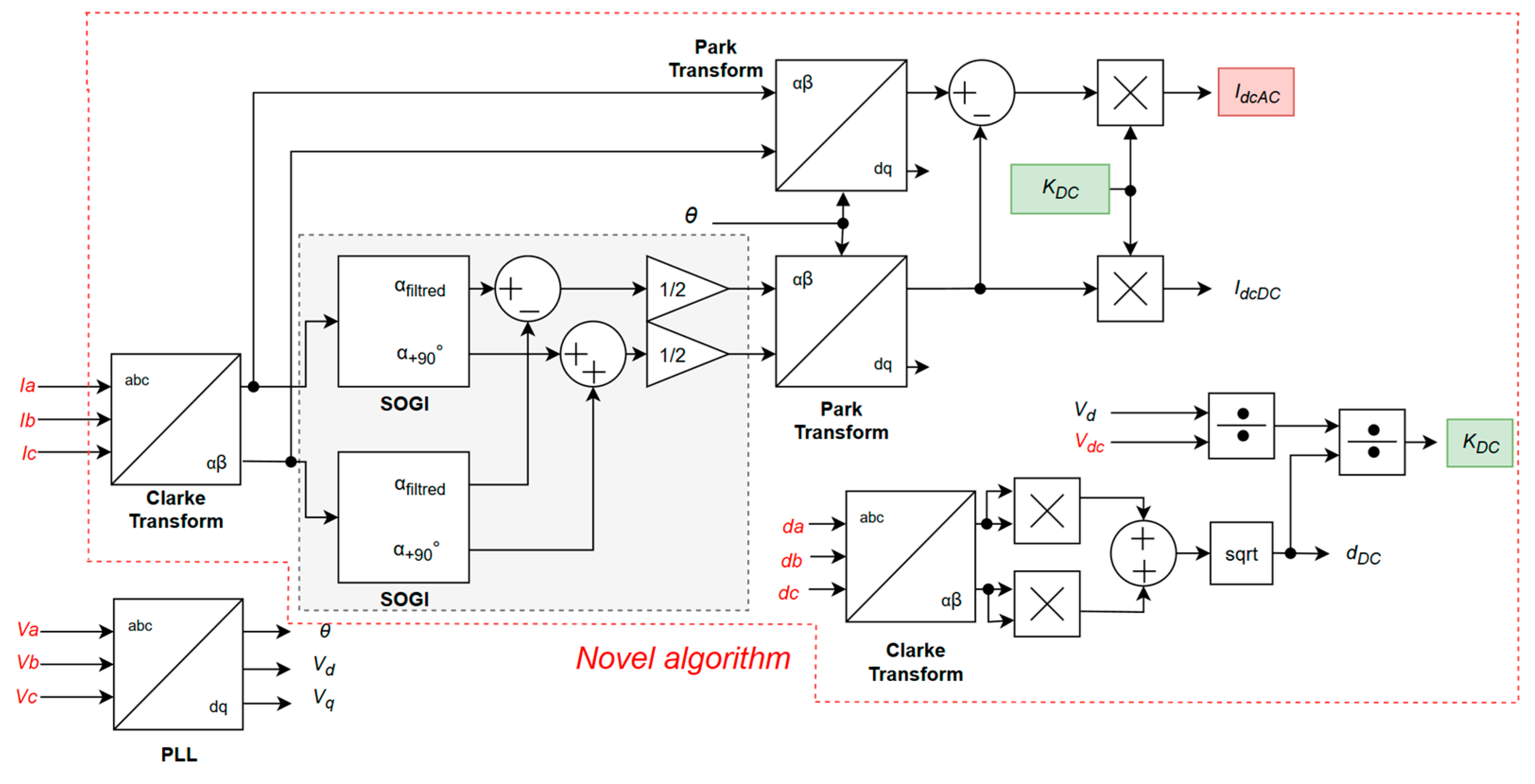
The proposed method for sensorless calculation of the DC-link current, illustrated in
Figure 1, is based on the Second Order Generalized Integrator algorithm (SOGI) [
20], which serves as an effective quadrature signal generator offering robust filtering properties, particularly for suppressing harmonic distortions and DC offsets. This is achieved through its dual transfer functions:
where
is the angular fundamental frequency, and
is the damping factor of the SOGI algorithm.
The first is a band-pass filter (3) for the in-phase signal, and the second is a low-pass filter with a 90° phase shift for the quadrature signal (4). These properties allow the SOGI to provide clean αβ components, which are fundamental for precisely calculating the DC-link current.
In the proposed algorithm, the SOGI filter is utilized to extract the positive- and negative-sequence components of the input current on the AC side of the converter. Based on symmetrical component decomposition theory, any unbalanced three-phase system can be represented as a combination of three separate three-phase systems, as described by Equation (5). The first two components correspond to balanced sequences rotating in opposite directions, whereas the third component represents a pulsating sequence with angular frequency
ωt. This decomposition enables precise analysis and control of asymmetrical operating conditions in AC/DC conversion systems.
where
I+, I−, and
I0 are the magnitudes of currents of symmetrical components.
Additionally, it is possible to remove one of the equations by converting Equation (5) to the αβ reference system (6), where the Clarke transform is applied.
where ∅
+ and ∅
− are the phases of symmetrical components obtained from PLL loop of inverter.
Subsequently, the signal was split into two independent processing paths. One path is processed using the SOGI filter, which effectively suppresses unwanted components and isolates only the fundamental frequency component of the input signal. Both processed signals are then subjected to Park transformation, as defined in Equations (7) and (8), enabling their representation in a rotating reference frame for further analysis and control, where the phase reference angle is derived from the PLL of the converter.
The component
is of particular interest because it is directly associated with the current pulsation on the DC link of the power inverter. Given that the signal processed through the SOGI filter retains only the fundamental frequency component, its d-axis projection corresponds to the DC component drawn from the inverter DC link. The resulting difference represents the AC component of the current drawn by the inverter from the DC link by subtracting this value from the double-axis component of the second signal.
Since the proposed algorithm relies solely on AC-side voltage and current measurements to estimate the DC-link current, a conversion of these quantities to the DC side is necessary. To enable this, a dedicated scaling mechanism was introduced in the algorithm to translate the magnitude of AC-side signals into their corresponding DC-side equivalents. This scaling coefficient, denoted as
in the algorithm diagram, is mathematically defined in Equation (9).
where
is the DC-link voltage,
is the modulation index magnitude of the converter, and
is the d-axis voltage component of the AC side of the converter.
All the variables utilized in the proposed algorithm are either directly measured or derived as part of the standard operation of the converter. The overall control structure of the system is illustrated in
Figure 2. As shown in the diagram, the AC component compensator for the DC link operates without the need for additional measurement systems, relying solely on the signals already available from the inverter.
In the investigated system, an unisolated buck–boost converter integrated with a supercapacitor bank is employed to mitigate the AC component of the DC-link current. The implementation of this compensation system follows the schematic shown in
Figure 3.
3. Results
The capability to compensate for pulsations on the DC link of the power inverter was evaluated using a dedicated laboratory test bench, as depicted in
Figure 4. The control algorithm for the power modules, along with the sensorless AC current estimator, was developed in the MATLAB 2021B and Simulink environments and subsequently implemented on a Texas Instruments TMS320F28379D microcontroller through automatic code generation. The proposed algorithm does not incorporate closed-loop controllers and is therefore executed at the same frequency as the switching frequency of the AC/DC converter transistors. The experimental results indicate that the minimum execution frequency required for proper operation is at least 20 times the fundamental grid frequency of 50 Hz. Below this threshold, signal distortions emerge, negatively affecting the performance and quality of the compensation process. The output signal
generated by the proposed algorithm, which serves as the reference current signal, generated by the proposed algorithm, was produced via the DAC of the microcontroller and measured using an oscilloscope.
All measurements were conducted by initially operating the inverter under asymmetrical conditions without compensation on the DC link, followed by activation of the compensator. In both cases, the 100 Hz component was determined relative to the DC component. In addition, the instantaneous active and reactive power components were analyzed for each phase. To quantitatively assess the reduction in the AC component in the DC-link current, the measured current was subjected to Fourier analysis using a tool available in the Specialized Power Systems library of the MATLAB environment. This analysis enabled the evaluation of whether the operation of the compensator introduces current oscillations into higher frequency ranges. The experimental results demonstrated that the increase in higher-order harmonics caused by the compensator is limited to the fifth harmonic of the 100 Hz component. For clarity of presentation, the spectral analysis was extended up to the tenth harmonic of this component.
A current-measurement transducer was integrated into the DC link of the AC/DC power converter, appropriately scaled, and connected to an oscilloscope for signal acquisition. This enabled a comparative analysis between the measured values and those determined by
. The key electrical parameters monitored during the experimental tests included
, representing the three-phase output current from the AC/DC converter;
, denoting the voltage and current on the DC link; and
, corresponding to the compensation algorithm output. All measured signals were recorded using two synchronized oscilloscopes to ensure precise data acquisition. The Tektronix MSO5034B was used to measure currents on the AC side, while the Tektronix DPO5054B captured other signals. Power measurements were obtained from the converter controller via a 14-bit DAC connected directly to the oscilloscope. The experimental setup consisted of five primary components, and their respective parameters are listed in
Table 1.
To mitigate the influence of the floating voltage of the capacitor on the measurement accuracy, a high-capacity capacitor was selected. Throughout all experimental scenarios, the AC/DC inverter operated under asymmetrical conditions while interfaced with the utility grid via a transformer with a voltage reduction ratio. The presence of significant asymmetry in system operation resulted in the generation of high-amplitude AC components on the DC link of the inverter. The laboratory testing procedure was divided into three distinct phases. The test scenarios were selected to represent the most challenging conditions in terms of DC-link current pulsation levels in order to evaluate the effectiveness of the proposed system under the most demanding and practically relevant operating modes. These include voltage balancing, reactive power compensation, and energy storage charging, which are of particular interest from both the user and grid perspectives:
Case 1: High current asymmetry: Two phases deliver active power to the grid (
), while one phase draws active power from the grid
, with no reactive power present
(
Figure 5);
Case 2: Phase c delivers active power to the grid
, phase b has no power exchange
, and phase a supplies capacitive reactive power to the grid
(
Figure 6);
Case 3: Current asymmetry during energy storage charging: All phases draw active power from the grid
, with no reactive power present
(
Figure 7).
In case 1, as shown in
Figure 5, the operation of the converter was analyzed in a scenario where the two phases functioned as active power compensators, while the third phase operated as a rectifier. The reactive power balance of the converter remains zero. The DC-link current
reaches an amplitude of 10 A and periodically crosses the zero value, indicating that the energy storage system undergoes continuous charging and discharging cycles at a frequency of 100 Hz. The ratio of the 100 Hz component to the DC component was determined to be 236%.
Upon activation of the compensating DC/DC converter, a significant reduction in the AC component amplitude was observed. Notably, the current waveform no longer intersects the x-axis, indicating effective suppression of pulsations. As a result, the ratio of the 100 Hz component to the DC component decreased to 21.5%.
In case 2, as shown in
Figure 6, the converter operated under a high level of asymmetry. The first phase functioned as an active power compensator, the second phase did not exchange power with the grid, and the third phase functioned as a reactive power compensator. Under these conditions, the asymmetry of the DC link reached an amplitude similar to that observed in case 1, with a peak current of 10 A. The DC-link current also crossed the zero value and exhibited negative values, indicating the periodic charging and discharging of the energy storage system at 100 Hz. The 100 Hz component relative to the DC component was measured to be 264%.
Following activation of the compensating DC/DC converter, a significant reduction in the AC component of the DC-link current was achieved. The 100 Hz component was successfully reduced to 19%, while the total AC component content was minimized to 22%.
In case 3, as shown in
Figure 7, the asymmetrical energy storage charging scenario was analyzed. All the phases of the converter operated as rectifiers, drawing active power from the grid in an asymmetrical manner. Under these conditions, the DC-link current pulsation reached an amplitude of 5 A without crossing the zero value. The 100 Hz component relative to the DC component was measured as 42%.
After activating the compensating DC/DC converter, a substantial reduction in the AC component of the DC-link current was achieved. The 100 Hz component was reduced to 2.4%, while the total AC component content decreased to 4.9%.
This represents a significant improvement, particularly when compared to the author’s previous work [
13], in which a preliminary, simplified version of the algorithm was investigated. In that study, pulsation reduction of approximately 80% was achieved, lowering the DC-link current oscillation from 8 A to 1.5 A. However, the compensation strategy in that case relied on an isolated Dual Active Bridge (DAB) converter, which may have influenced the effectiveness of the algorithm. The influence of converter topology on compensation performance will be addressed in the author’s future research.
4. Discussion
This study investigated the issue of DC-link current pulsations in four-wire AC/DC converters with energy storage operating under asymmetrical load conditions. The motivation behind this research stems from the increasing role of microgrids in modern power systems, in which independent phase control is employed to mitigate voltage asymmetry. Although this method enhances microgrid performance, it simultaneously introduces DC-link current pulsations, which may adversely impact the efficiency and lifespan of energy storage systems.
Unlike other methods, the sensorless compensation algorithm proposed in this study eliminates the need for additional sensors by utilizing the existing voltage and current measurements on the AC side, which are already required for the operation of the converter. The algorithm incorporates an SOGI filter, enabling precise detection and compensation of pulsations without significantly increasing the system complexity. This innovative approach allows for the dynamic correction of DC-link current pulsations, thereby protecting the energy storage system.
In all tested scenarios, the magnitude of the AC component was significantly reduced upon activating the compensator. Even under the most challenging conditions, where severe asymmetry caused the AC component to exceed the DC component, leading to alternating charging and discharging of the energy storage system, the proposed solution effectively mitigated these oscillations. After the compensator was enabled, the AC component was substantially reduced, and the issues of alternating charging and discharging were eliminated. This effect was particularly pronounced in cases 1 and 2, where the AC component prior to compensator activation reached 7 A and was subsequently reduced to approximately 1.4 A and, in case 2, where it decreased from 3 A to 0.5 A. The effectiveness of this reduction is further confirmed by the FFT analysis, which indicates that the relative amplitude of the AC component was reduced from 240% to 21.5% in case 1 and from 264% to 22% in Case 2.
The method proved to be effective across all operating modes of the converter, as confirmed by additional measurements in case 3, where the system was tested under asymmetrical energy storage charging conditions. In this case, the AC component on the DC link was reduced from 2.5 A to almost 0 A. In the FFT analysis, this corresponds to a reduction from 42% to 4.9%, demonstrating the robustness of the proposed approach even under significant phase current imbalance conditions.
5. Conclusions
The outcome of the authors’ work is a novel and innovative algorithm for compensating the AC component of the DC-link current in a power converter, which operates solely based on voltage and current measurements taken on the AC side of the converter. The proposed method for DC-link current pulsations was experimentally validated under highly asymmetrical load conditions. The results demonstrated significant reduction in the AC component in all tested cases, confirming the method’s effectiveness and robustness. By eliminating the need for additional sensors and leveraging existing measurements, the solution reduces both complexity and cost. The study highlights the potential of integrating such sensorless algorithms with DC/DC interfaces for improved energy storage performance and microgrid stability.
Future research endeavors will aim to expand the analyzed system by incorporating various DC/DC converter topologies, including isolated configurations, to further optimize the performance of the DC-link pulsation compensator. The current findings indicate that a non-isolated buck–boost converter effectively reduces AC oscillations on the DC link. However, in applications requiring greater flexibility in energy management, isolated DC/DC converter topologies, such as Dual Active Bridge (DAB) and Full-Bridge LLC, may offer additional advantages. The resonant operation mode of the Full-Bridge LLC converter has the potential to enhance the energy efficiency at higher switching frequencies. Moreover, galvanic isolation of the supercapacitor from the main energy storage system may improve the system safety by mitigating the direct influence of the low-impedance energy source on the energy storage unit. This could contribute to the reduction in uncontrolled current flows, thereby enhancing the system reliability. Planned experiments will compare different topologies in terms of pulsation compensation efficiency and their impact on power quality parameters.


